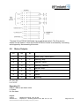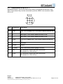
1
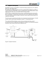
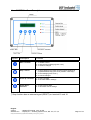
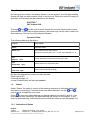
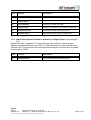
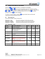
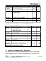
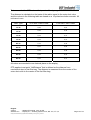
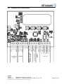
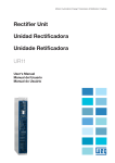
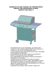
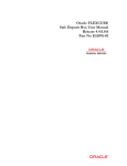
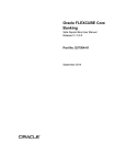
Installation Manual
®
ECOTROL Control
English
Version
Software rev.
: 200508_ETmanual_ver2_05-UK
: Display: 2.2 Cleaning system: ET01; DS: 2.4; CT: 2,3
Table of Contents
1.0
1.1
1.2
1.3
General Description ............................................. 3
ECOTROL Front Description ...................................................................................... 4
Display - Indication of Data ......................................................................................... 5
Status .......................................................................................................................... 5
1.3.1
1.3.2
1.3.3
1.3.4
Indication of Status ......................................................................................................... 6
Warning Description ......................................................................................................... .6
Alarm Descriptions ............................................................................................................ 6
Alarm Descriptions Related to Activation of Digital Input .................................................. 7
2.0
Access and Setup of Setpoints ..................................... 8
2.1 Setpoints List............................................................................................................... 8
2.1.1
2.1.2
2.1.3
Setpoints - User................................................................................................................. 8
Setpoints - Engineer .......................................................................................................... 9
Setpoints - System Settings .............................................................................................. 9
2.2 Encoder Step Distance (ESD)..................................................................................... 9
3.0
Function Selection ............................................. 11
3.0.1
3.0.2
3.0.3
Differential Control........................................................................................................... 11
Time Control .................................................................................................................... 11
Combined Differential/Time Control ................................................................................ 11
3.1 Start........................................................................................................................... 11
3.2 Errors Related to Commissioning ............................................................................. 11
3.3 Stop........................................................................................................................... 12
3.3.1
3.3.2
3.3.3
4.0
Stop Final Cleaning ......................................................................................................... 12
Immediate Stop ............................................................................................................... 12
Stop via External Connection .......................................................................................... 13
Service ...................................................... 13
4.0.1
4.0.2
Warning !! ........................................................................................................................ 13
Service Mode for DS Equipment ..................................................................................... 13
4.1 Compressor Check ................................................................................................... 13
4.2 Valve Numbering....................................................................................................... 13
5.0
Display Unit Connections ........................................ 14
5.2 Terminal Description ................................................................................................. 15
5.1 Status Outputs .......................................................................................................... 16
5.3 Connections on 9p CPC11........................................................................................ 17
5.4 Terminal box SB001 on the outside of the top section.............................................. 18
6.0 Electrical and Air connection . . . . . . . . . . . . . . . . . . . . . . . . . . . . . . . . . . . . . . . . . . . .
19
English
Version
Software rev.
: 200508_ETmanual_ver2_05-UK
: Display: 2.2 Cleaning system: ET01; DS: 2.4; CT: 2,3
1.0
General Description
ECOTROL® has been developed to control the cleaning sequences in CT and DS
filters from JKF Industri A/S.
By means of the display unit the user can see actual data and adjust a number of
control parameters. ECOTROL® can run as stand alone (must always have a start
signal from the main fan) or interfaced with PLC/relay control.
If ECOTROL® is initiated without time control, the differential pressure across the
filter is monitored. A user set point defines the time for the cleaning to be initiated.
The actual airflow in the filter bags is measured, and the optimal shot pressure for
cleaning is calculated.
The time control mode allows the filter to be cleaned at intervals between 10-1440
minutes. Each interval can be defined to include 1-10 cleaning events.
The combined differential/time control works according to the time control
procedures. However, additional cleaning will be initiated if the differential pressure
across the filter should exceed the pre-defined value.
Figure 2. System Overview
English
Version
Software rev.
: 200508_ETmanual_ver2_05-UK
: Display: 2.2 Cleaning system: ET01; DS: 2.4; CT: 2,3
I:\Salg teknik\Filtre\Filterstyringer\ECOTROL\200508_ETmanual_ver2_05-UK.doc
Page 3 of 19
ECOTROL® Front Description
1.1
Symbol
1
1
Description
Function
Start / Confirm
1: To initiate control
2: To get access to settings (press 3 sec.)
3: To confirm changes
Stop / Cancel
1: To stop cleaning (one press and the ongoing cleaning is
completed before stop) (two short presses – total stop)
2: To exit settings (press 3 sec.)
3: To cancel changes
Scroll up / Increase
1: To see next data
2: To increase data in settings
Scroll down /
Decrease
1: To see previous data
2: To decrease data in settings
)
) Stop function also as external signal (RESET) on terminal 15 and 16.
English
Version
Software rev.
: 200508_ETmanual_ver2_05-UK
: Display: 2.2 Cleaning system: ET01; DS: 2.4; CT: 2,3
I:\Salg teknik\Filtre\Filterstyringer\ECOTROL\200508_ETmanual_ver2_05-UK.doc
Page 4 of 19
1.2
Display - Indication of Data
On turning on the control, the display shows a “chess square”, and the light-emitting
diodes will light one after another so as to test the unit. When the control is ready for
operation, the following will be indicated on the display:
ECOTROL®
JKF Industri A/S
The keys
and
can be used to scroll through the various measurement inputs
and statuses. In the event of alarm/warning, the same keys can be used to see such
alarm/warning. The top line of the display indicates:
Operation Data:
The following data may be shown:
Display
Description
Status
Operation status
Alarm “no.”:
Only visible if one or more alarms/
Warnings are active (alarm “no.” is read, see paragraph 1.3.1)
Inlet
Diff.Pres
xxxx
Actual differential pressure across filter (mm WG)
Inlet
Compr.Pres xxxx
Actual pressure in compressor (bar)
Inlet
Filter Flow xxxx
Air velocity in filter bag (m/s)
(Only measured during cleaning)
By start the programme version can also be read.
Control panel 2,2
Cleaning carriage 1,2
In case of alarms they will also be readable.
1.3
Status
Under “Status” the state of control in the cleaning sequence is indicated along with
and
any alarms or warnings. If several errors have been detected, use the
keys to scroll through the error items.
Press
to reset any alarm/warning or external signal on terminal 15 and 16. If an
error has not been corrected, the alarm/warning will remain on the display. In the
event of alarm/warning, technical personnel should be called in (see paragraph 3.2).
1.3.1 Indication of Status
English
Version
Software rev.
: 200508_ETmanual_ver2_05-UK
: Display: 2.2 Cleaning system: ET01; DS: 2.4; CT: 2,3
I:\Salg teknik\Filtre\Filterstyringer\ECOTROL\200508_ETmanual_ver2_05-UK.doc
Page 5 of 19
The top line of the display indicates: Status:
The following operation function/alarms/warnings may be shown:
Display
Description
Stop, Service
Control under service – no cleaning
Stop
Control has stopped - no cleaning
Cleaning
Control is cleaning
Pause
Control awaits start conditions for cleaning
Stop, Alarm
Critical equipment fault
Control has stopped
Stop, Warning
The control has stopped – no cleaning
No critical equipment fault – can operate at reduced
capacity.
Cleaning, Warning
The control is cleaning.
No critical equipment fault – can operate at reduced
capacity.
Pause, Warning
The control awaits start conditions for cleaning
No critical equipment fault – can
operate at reduced capacity.
Initiating
Control is preparing for operation
Initiating, Warn.
Control is preparing for operation - can operate at reduced
capacity
In front of each status item, two symbols may occur, * and +.
* = will indicate that control awaits compressor timeout, defined in set-point
Compr.Pause (see paragraph 2.1.3).
+ = will indicate that control is running final cleaning.
1.3.2 Warning Description
The top line of the display indicates:
Warning:
Item
Display
Description
10
Valve Number “No”
Defective valve No. “No”
The valve number is counted out from the middle.
1.3.3 Alarm Descriptions
The top line of the display indicates:
English
Version
Software rev.
: 200508_ETmanual_ver2_05-UK
: Display: 2.2 Cleaning system: ET01; DS: 2.4; CT: 2,3
I:\Salg teknik\Filtre\Filterstyringer\ECOTROL\200508_ETmanual_ver2_05-UK.doc
Page 6 of 19
Alarm:
Item
Display
Description
20
More Valves
Several defective valves
32
Service Active
(DS only!) Service mode - for opening of the roof
40
VLT Not Ready
Frequency converter not ready
41
Position Error
Encoder, VLT (frequency converter) or motor fault
42
Compressor Error
Compressor unable to build up pressure
43
Diff.Pres. Error
Differential pressure gauge (JK-500D) fault
See also paragraph 3.2
1.3.4 Alarm Descriptions Related to Activation of Digital Input (see paragraph
5.0)
Digital input, IN2, is applied in CT equipment for door switch in order to protect
against unintentional access to the filter. For DS equipment the input is used as an
external stop. The input has been provided with internal pull-up and will be activated
by interruption (NPN).
Item
Display
Description
30
Ext. Stop Active
IN2 is/was activated (see paragraph 5.2)
English
Version
Software rev.
: 200508_ETmanual_ver2_05-UK
: Display: 2.2 Cleaning system: ET01; DS: 2.4; CT: 2,3
I:\Salg teknik\Filtre\Filterstyringer\ECOTROL\200508_ETmanual_ver2_05-UK.doc
Page 7 of 19
2.0
Access and Setup of Set points
Press the
key until “Setup, Select” is indicated on the display.
Then use the
and
keys to scroll through the menu list. To adjust a setting,
press shortly
and “Setup, Change” will be indicated on the display. Then use the
and
keys to increase or decrease data by one unit. Press
to confirm
changes, or press
to cancel changes.
To return to normal display, press the
measurement data selected is shown.
key and hold it down until the last
2.1
Set points List
The control includes 3 types of set points:
Set points - User
Set points - Master
Set points - System
Set points necessary for the daily operation
Set points to adjust and service the equipment
Set points for primary setup of the equipment
2.1.1 Set points - User
Display
Set point Description
Min.
Max.
Diff.
Press.
Time/D.Press
Std.
Lng./Spr:
Selection of language
Fnc.:
Selection of cleaning function
Differential pressure/Time
control/Diff.&Time
StartPress.
Start differential pressure (mmWG)
0
500
100
CleanIntrv.
Cleaning interval when time control
(Minutes)
10
1440
60
No.OfClean.
Number of cleaning events when time
control
1
10
1
ServiceMode
Note! To be used with DS equipment
only !!
Activation of service mode
No
Yes
No
Open Top:
Note! To be used with DS equipment
only !!
Opening of the roof
No
Yes
No
MasterSetup:
Indication of MasterSetup
No
Yes
No
Time/D.Pres
Note! On Fnc/ServiceMode/MasterSetup, only relevant settings are shown.
English
Version
Software rev.
: 200508_ETmanual_ver2_05-UK
: Display: 2.2 Cleaning system: ET01; DS: 2.4; CT: 2,3
I:\Salg teknik\Filtre\Filterstyringer\ECOTROL\200508_ETmanual_ver2_05-UK.doc
Page 8 of 19
2.1.2 Set points - Engineer
Display
Set point Description
Min.
Max.
Std.
Lo.ShotPrs.
Minimum shot pressure (bar)
1,5
Max-0,1
2,0
Hi.ShotPrs.
Maximum shot pressure (bar)
Min +0,1
5,5
3,5
Flow Measur.
Activation of flow meter
No: No flow measuring
1:Flow measuring by AFS035
2:Flow measuring by JK-500D
(100 mmWG)
No
2
2
Min. Flow
Flow similar to Minimum “Lo.ShotPrs.”
1
Max-0,1
1,0
Max. Flow
Flow similar to Maximum “Hi.ShotPrs.”
Min +0,1
35
20
SystemSetup
Indication of system settings
No
Yes
No
Note! On selection of FlowMeasur. only relevant settings are shown.
2.1.3 Set points - System Settings
Display
Setpoint Description
FilterType:
Selection of filter type
1: CT36 2: CT60 3: CT84
4: CT90 5: DS12 6: DS20
7: DS28 8: DS36 9: DS44
Filt.Length
Bag length (metres)
EncoderImp.
Encoder pulses per revolution
GearRatio
Gear exchange *
NulDistance
Min.
Max.
Std.
2,0
4,0
5
20
10
250,0
500,0
380,9
Distance mechanical stop to first bag row
(ETD)
0
1000
Park.Angle
Parking position (°)
0
340
FlowMs.Time
Time from stop to flow measuring
0,0
2,0
0,5
Compr.Pause
Minimum pause for compressor (seconds)
180
500
240
Ext. Compr. Air
Is external compressed air used
No
Yes
* See paragraph 2.2 for settings
2.2
Encoder Trin Distance (ETD) - explanation
The “disparate” jumps in some of the settings have been described in the following.
Encoder Trin Distance (ETD) is defined as the distance equal to one encoder step.
English
Version
Software rev.
: 200508_ETmanual_ver2_05-UK
: Display: 2.2 Cleaning system: ET01; DS: 2.4; CT: 2,3
I:\Salg teknik\Filtre\Filterstyringer\ECOTROL\200508_ETmanual_ver2_05-UK.doc
Page 9 of 19
This means that the ETD value will depend on filter type, gear and encoder.
The distance is calculated on the basis of the radius equal to the outer shot valve,
and the values in the following table are based on a 10-pulses/revolution encoder. All
units are in mm.
Filter Type
ETD with 1:348.0 Gear
ETD with 1:380.9 Gear
CT-36
0,26
0,24
CT-60
0,35
0,32
CT-84
0,43
0,41
CT-90
0,43
0,41
DS-12
0,19
0,18
DS-20
0,27
0,26
DS-28
0,32
0,30
DS-36
0,40
0,37
DS-44
0,44
0,41
All values are rounded to one decimal place on the display.
ETD applies to set point “NulDistance” that is defined as the distance from
mechanical stop to first filter bag. The distance is measured from the centre of the
outer shot valve to the centre of the first filter bag.
English
Version
Software rev.
: 200508_ETmanual_ver2_05-UK
: Display: 2.2 Cleaning system: ET01; DS: 2.4; CT: 2,3
I:\Salg teknik\Filtre\Filterstyringer\ECOTROL\200508_ETmanual_ver2_05-UK.doc
Page 10 of 19
3.0
Function Selection
The operation mode is selected by means of set point.
3.0.1 Differential Control
In this control mode the differential pressure across the filter is continuously
monitored. The user set point StartPress defines the time for the cleaning to be
initiated. Once cleaning has been finished, the carriage will return to parking position
and await next increase in pressure.
3.0.2 Time Control
This control mode allows the filter to be cleaned at intervals between 10-1440
minutes (set point CleanIntrv.). Each interval can be defined to include 1-10 cleaning
events (set point No.OfClean.).
The cleaning is based on time only, irrespective of the differential pressure across
the filter.
3.0.3 Combined Differential/Time Control
This control mode works according to the time control procedures. However,
additional cleaning will be initiated if the differential pressure across the filter should
exceed the pre-defined value.
3.1
Start
To start up for the first time or after a stop, press . The control can also be
activated externally via input “start/stop” on the display unit (see paragraph 5.2
Terminal Description).
Before cleaning, a “preparing event” will elapse. The text “Initiating” will be indicated
under the “Status” menu.
Finally, depending on whether the cleaning condition has been complied with,
the cleaning carriage will go to the pre-defined parking position,
or it will go direct to the first position in the cleaning sequence.
3.2
Errors Related to Commissioning (starting up)
Especially during commissioning, errors may occur.
The reasons for some of the occurrences of “Alarm 41: Position Error” related to the
preparing event have been described in the following.
“Alarm 41” will be reported if the control signals to the motor to run in one direction
and receives a signal from the encoder that the motor has come to a standstill or
runs in the opposite direction.
“Alarm 41” can also be due to a fault somewhere from the control through VLT
(frequency converter), motor, gear, encoder and back to the control. Also certain
mechanical defects may activate this alarm.
“Alarm 41” will normally be activated if something should become squeezed during
the daily operation.
English
Version
Software rev.
: 200508_ETmanual_ver2_05-UK
: Display: 2.2 Cleaning system: ET01; DS: 2.4; CT: 2,3
I:\Salg teknik\Filtre\Filterstyringer\ECOTROL\200508_ETmanual_ver2_05-UK.doc
Page 11 of 19
If the cleaning carriage does not move at all, and alarm occurs approx. 8 seconds
after start, the reason could be one of the following:
•
•
•
•
•
•
Error in connections from VLT to motor
Motor lacks a phase
Motor is not connected to 3 x 230 V AC (must be a delta connection)
Error in connections from control to VLT
Transport protection has not been removed
Defect motor, gear, VLT or controlling board
If the cleaning carriage moves forth for one second and then a sudden step back and
forth:
•
•
•
•
Error in connections from control to encoder
The two-encoder outputs have been switched
Missing magnet on motor shaft (if hall type encoder)
Defect encoder or controlling board
If the cleaning carriage moves back for one second and then a sudden step forth and
back:
•
Motor has been phased incorrectly
If the cleaning carriage goes the wrong way during the entire preparing event:
•
Motor has been phased incorrectly; the two-encoder outputs have been
switched
If the cleaning carriage moves forth for one second and the back toward mechanical
stop for a long time:
•
•
3.3
Gear has been fastened improperly on centre shaft
Defective gear or mechanical stop.
Stop
3.3.1 Stop Final Cleaning
Press
once to stop an ongoing cleaning event (at minimum shot pressure). The
control will be idle while the compressor pauses (set point Compr.Pause) whereupon
final cleaning will be initiated. Final cleaning will be performed at minimum shot pressure
(set point Lo.ShotPrs.). The carriage returns to parking position.
3.3.2 Immediate Stop
twice. The carriage will not
At any time the control can be discontinued by pressing
return to parking position. On pressing
either the cleaning event will be initiated if the
conditions are present, or the carriage will return to parking position.
English
Version
Software rev.
: 200508_ETmanual_ver2_05-UK
: Display: 2.2 Cleaning system: ET01; DS: 2.4; CT: 2,3
I:\Salg teknik\Filtre\Filterstyringer\ECOTROL\200508_ETmanual_ver2_05-UK.doc
Page 12 of 19
3.3.3 Stop via External Connection
On stopping cleaning via the external connection, any ongoing cleaning event will be
stopped (at minimum shot pressure). The control will be idle while the compressor
pauses (set point Compr.Pause) whereupon final cleaning will be initiated. Final
cleaning will be performed at minimum shot pressure (set point Lo.ShotPrs.). The
carriage returns to parking position.
4.0
Service
4.0.1 WARNING !!
Great care is required during any access to the filter. It is deadly dangerous to shortcircuit the safety device that protects against unintentional access during operation.
The control should be turned off or set in service mode (see below) before access to the
filter is made.
4.0.2 Service Mode for DS Equipment
Select parameter ServiceMode (see paragraph 2.0 Access and Setup of Set points) and
set data to “Yes”.
The control is now in service mode, and the roof can be opened by means of parameter
Open Top
4.1
Maintenance of flow meter
At least once each 6th month the flow meter type JK-500D (100 mm) must be inspected.
The internal fitted filter on the high-pressure side is replaced. The filter on the lowpressure side is checked and cleaned by compressed air or alternatively replaced.
4.2
Compressor Check
When the equipment is inspected for the first time, it is important to check the
compressor revolution direction.
The test button on switches C5 (see Manual for control cabinet) can be used for manual
operation of the compressor. An arrow on the compressor jacket indicates the motor
revolution direction.
4.3
Valve Numbering
Valve No. 1 is located closest to the motor. The other valves have been numbered
so that the last one has been located farthest toward the wall of the filter.
English
Version
Software rev.
: 200508_ETmanual_ver2_05-UK
: Display: 2.2 Cleaning system: ET01; DS: 2.4; CT: 2,3
I:\Salg teknik\Filtre\Filterstyringer\ECOTROL\200508_ETmanual_ver2_05-UK.doc
Page 13 of 19
5.0
Display Unit Connections
English
Version
Software rev.
: 200508_ETmanual_ver2_05-UK
: Display: 2.2 Cleaning system: ET01; DS: 2.4; CT: 2,3
I:\Salg teknik\Filtre\Filterstyringer\ECOTROL\200508_ETmanual_ver2_05-UK.doc
Page 14 of 19
5.1
Terminal Description
Item
Designation
Description
1
+24V
+24 V DC to display unit. From control cabinet terminal X4-37
2
X
Bus signal. From control cabinet terminal X4-38
3
Y
Bus signal. From control cabinet terminal X4-39
4
COM
-24 V DC to display unit. From control cabinet terminal X4-40
5
+24V
+24 V DC to differential pressure gauge. From control cabinet
terminal X4-22
6
IN1
Analogue input from differential pressure gauge. From control
cabinet terminal X4-23
7
COM
Not used
8
Not used
9
Not used
10
Not used
11
IN2
CT-equipment: digital input from door switch
DS-equipment: external stop
12
COM
CT-equipment: digital input from door switch
DS-equipment: external stop
13
IN3
Digital input from PLC/relay. External start/stop signal *
14
COM
Digital input from PLC/relay. External start/stop signal *
15
IN4
External RESET. Has the same function as the key
16
COM
External RESET. Has the same function as the key
17
OUT1
Status output S1 to PLC
18
COM
Status output S1 to PLC
19
OUT2
Status output S2 to PLC
20
COM
Status output S2 to PLC
21
OUT3
Status output S3 to PLC
22
COM
Status output S3 to PLC
* Terminals 13 and 14 are connected with a switch. Switch on/off to initiate/stop cleaning.
English
Version
Software rev.
: 200508_ETmanual_ver2_05-UK
: Display: 2.2 Cleaning system: ET01; DS: 2.4; CT: 2,3
I:\Salg teknik\Filtre\Filterstyringer\ECOTROL\200508_ETmanual_ver2_05-UK.doc
Page 15 of 19
*Terminal 13 and 14 are connected via an end-/break switch. The filter plant is
started via this switch. In this way the ECOTROL®-Control is activated by connecting
and stopped by disconnecting the switch.
5.2
Status Outputs
S1
S2
S3
L
L
L
Alarm, Stop / Power failure
H
L
L
Warning, Stop
H
H
L
Warning, Pause
L
H
L
Warning, Cleaning
L
L
H
Service, Stop
H
L
H
Stop
H
H
H
Pause
L
H
H
Cleaning
H= 24 V DC
L= 0 V DC
Regarding S3
Can be used as an alarm outlet
L= Alarm
H= No alarm
English
Version
Software rev.
: 200508_ETmanual_ver2_05-UK
: Display: 2.2 Cleaning system: ET01; DS: 2.4; CT: 2,3
I:\Salg teknik\Filtre\Filterstyringer\ECOTROL\200508_ETmanual_ver2_05-UK.doc
Page 16 of 19
5.3
Connections on 9p CPC11
As indicated below, connections have been made to the socket on the front of 9p
CPC11 from where they can be connected to joint box SB001 via connection cable
CPC-9-13.
Item
Designation
Description
1
+24V
+24 V DC to display unit. From control cabinet terminal X437
2
X
Bus signal. From control cabinet terminal X4-38
3
Y
Bus signal. From control cabinet terminal X4-39
4
COM
-24 V DC to display unit. From control cabinet terminal X440
5
Not used
6
Screen
Screen
7
4..20mA
From differential pressure gauge JK-500D
8
IN2
CT equipment: digital input from door switch
DS equipment: external stop
9
COM
CT equipment: digital input from door switch
DS equipment: external stop
English
Version
Software rev.
: 200508_ETmanual_ver2_05-UK
: Display: 2.2 Cleaning system: ET01; DS: 2.4; CT: 2,3
I:\Salg teknik\Filtre\Filterstyringer\ECOTROL\200508_ETmanual_ver2_05-UK.doc
Page 17 of 19
5.4 Terminal box SB001 on the outside of the top section
English
Version
Software rev.
: 200508_ETmanual_ver2_05-UK
: Display: 2.2 Cleaning system: ET01; DS: 2.4; CT: 2,3
I:\Salg teknik\Filtre\Filterstyringer\ECOTROL\200508_ETmanual_ver2_05-UK.doc
Page 18 of 19
6.0 Electrical and Air connection
Supply 230 V~ /400 V~
ECOTROL®-controller must always stand with voltage.
Connecting box (look 5.4)
Clamp
17 – N = N
16 – T = L3
1 L (14) + N (17)
= 230 V~
15 – S = L2
* 3 L (14, 15, 16) + N (17)
= 400 V~
14 – R = L1
13 – J/E = JORD
* Is necessary if the cleaning system is assembled with a 3-phased compressor.
Communication connections (passage 5.0-1-2)
External START/STOP (terminal (13 and 14)) must always be connected.
Alarm information from ECOTROL®-cleaning control system is read out from the state exits S1S2-S3.
External stop is an alarm contact. If this contact is disconnected, all cleaning stops and the
cleaning system is not able to run again until the contact is of and the alarm reset.
Standard connection of external stop:
- By CT-equipment external stop is not used. Clamp11 and 12 is short circuited in the
connecting box (look passage 5.4).
- By DS-equipment external stop clamp 11 and 12 are connected to the roof contact.
External reset
- Has got the same function as key
(look passage 3.3-1-2-3)
- External reset of alarm (look passage 1.3)
Connection of compressed air
Equipment which is prepared to clean with external compressed air, is connected to dry
compressed air by shot bush, ¼” internal screw thread.
Supply:
350 NL/min
Pressure:
Min.: 5,0 bar
Max.: 8,0 bar
For DS-36 and DS-44
Pressure:
Min.: 7,0 bar
Max.: 8,0 bar
English
Version
Software rev.
: 200508_ETmanual_ver2_05-UK
: Display: 2.2 Cleaning system: ET01; DS: 2.4; CT: 2,3
I:\Salg teknik\Filtre\Filterstyringer\ECOTROL\200508_ETmanual_ver2_05-UK.doc
Page 19 of 19