1
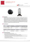
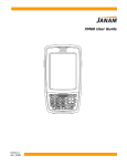
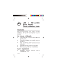
RS-232 Serial Server (FE2210/FE2220) User’s Manual 1 Copyright Statement No part of this publication may be reproduced in any form by any means without the prior written permission. Other trademarks or brand names mentioned herein are trademarks or registered trademarks of their respective companies. Disclaimer Information in this document is subject to change without notice. The manufacturer does not make any representations or warranties (implied or otherwise) regarding the accuracy and completeness of this document and shall in no event be liable for any loss of profit or any commercial damage, including but not limited to special, incidental, consequential, or other damage. Safety Instructions Always read the safety instructions carefully Keep this User’s Manual for future reference Keep this equipment away from humidity If any of the following situation arises, get the equipment checked by a service technician: • The equipment has been exposed to moisture. • The equipment has been dropped and damaged. • The equipment has obvious sign of breakage. • The equipment has not been working well or you cannot get it work according to User’s Manual. 2 Table of Contents 1. Introduction .....................................................................................4 Features ........................................................................................................4 Package Content...........................................................................................4 System Requirement ....................................................................................4 2. Specification....................................................................................5 1-Port RS232 Serial Server............................................................................6 Hardware Dimension ......................................................................6 Hardware Introduction ....................................................................7 2 -Port RS232 Serial Server...........................................................................8 Hardware Dimension ......................................................................8 Hardware Introduction ....................................................................9 3. Installation ..................................................................................... 10 Window Driver Installation .......................................................................10 Device Server Manager Installation...........................................................11 Virtual Serial Port Manager Installation ....................................................19 Installation Verification..............................................................................24 4. Connected Serial Device Server .................................................. 25 5. Regulatory Compliance................................................................ 26 FCC Conditions .........................................................................................26 CE ..............................................................................................................26 3 1. Introduction The Ethernet Serial Server connects remote RS-232 devices via Ethernet as an operation center between RS-232 serial devices and the Internet. Once your computer connects to the Ethernet Serial Server via Ethernet, the virtual ports can provide communication to devices without altering any applications on your computer. It not only provides fine remote communication but remove the restriction for distance. This server is quite suitable for applying remote data accessing, security monitoring, and manufacture automation. Features Real COM device driver for Windows Standard TCP/IP interface and versatile operation mode Convenient Windows utility for configuring multiple device server 15KVDC ESD immunity to serial interface Configure by web browser or Windows utility Wall mount support Package Content Before installing the serial server, please check the package contains the following items: Serial Device Server x1 AC Power Adapter x1 CD (Driver and User’s Manual) x1 System Requirement IBM Compatible computer or Mac Windows® 2000, Windows® XP, Windows Vista® 32/64 bit, Windows® 7, Mac OS® X v10.x Built-in USB port computer 64 MB RAM or higher Pentium® 233 MHz or higher 4 2. Specification Ports 1x RS-232 (FE2210) 2x RS-232 (FE2220) Connector Male DB9 FIFO 16 bytes ESD Protection 15 KV ESD Serial Communication Speed 1.2K~921.6KBps Interface 10/100 BaseT Ethernet Interface Connector RJ-45 Operating Temperature 0℃ to 55℃ Operating Humidity 5 to 95% RH Dimensions(LxWxH) 100x60x29 mm Regulatory Approvals FCC/CE 5 1-Port RS232 Serial Server Hardware Dimension 60 mm 6 Hardware Introduction Wall mount hole Power LED Serial Port 7 Status LED 2 -Port RS232 Serial Server Hardware Dimension 60 mm 8 Hardware Introduction Power LED Serial Port Status LED Serial Port Wall mount hole 9 3. Installation Note: Do not connect your devices to computer before driver installation. Window Driver Installation Please insert the provided CD into CD-ROM. 1. Please choose the Setup File of Serial to Ethernet Toolkit and click “Install” button, and the following Windows will appear. 10 2. Please click “Finish” to complete installation. Device Server Manager Installation 1. Please click Device Server Manager (will use DSM throughout this manual) program, and the DSM Main Menu will appear as below. 11 The DSM Main Menu will provide eight functions as below. A. DSM setting: To set up Search, Restore, and Reboot period. B. Search: To search a server by name. C. IP Search: To search a server by assigned IP. D. Setup: To manipulate parameters of a selected server E. Web Browser: To open the setup page for the selected server parameters. F. Restore: To restore default setting. G. Reboot: To reboot server. H. Upgrade: Upgrade firmware for a selected server. 12 2. Clicking the “Search” bottom of this page will perform the search function and list the matched servers in a list as you can find in the following picture The Device Status List will describe as below: Item Description No. Serial Server Number Device Name Serial Device Server name(16 byte Maximum string) MAC Address MAC address of Serial Device Server DHCP Enable or Disable IP If enable DHCP function, you will get a dynamic IP from DHCP server; otherwise, a static ID will be assigned. Port -Server Mode: Data packet Port -Client Mode: Destination Port Mode Client or Server Mode Status -Idle: TCP or UDP do not connect on server. -Connect: TCP or UDP do connect on server. 13 3. If the status of the server is in “Connected” which means data is still transmitting, DSM will disable setup, reset, reboot and firmware update functions from user end to avoid interrupting date transfer. Please click DSM setting and the following dialog box will appear. Parameters description: Item Description Search period To setup the search timeout period. Reset period To setup the reset timeout period. Reboot period To setup the reboot timeout period. 14 4. Please click “Search” item on DSM Function column and the searching dialog box will appear. There are two functions at Searching dialog box. A. Search: Start to search. B. Cancel: Cancel to search. Item Description Multicast To start to search through UDP multicast packet. IP Multicast IP address TTL Time to live Loopback Enable/Disable loopback of outgoing multicast packet Broadcast To search through UDP broadcast packet IP Broadcast IP address 5. Please click IP Search button and the following dialog box will appear. You can search the assigned IP server address through the IP Search function. Assigned IP Server: Please key-in the IP address in the IP column and click Search button to start to search. 15 6. Click “Device Setup” button on DSM Function column and the dialog box will appear. Item Description Device Name Device Name MAC address Multicast IP address DHCP Enable/ Disable DHCP client function Server Enable Server Mode Listening IP To perform search through UDP broadcast packet Data Listening Port Data Listening Port on Server Client Enable Client Mode Destination IP Remote host IP address Destination Port Remote host port TCP To transfer serial data packet through TCP UDP To transfer serial data packet through UDP 16 Multicast To transfer serial data packet through multicast Broadcast To transfer serial data packet through broadcast RS485 RS-485 mode RS422/RS232 RS-422 mode Netmask Subnet mask Gateway Gateway IP address DNS Server DNS Server IP address Transmit Timer Transmit serial data packet period 7. When you click Serial Port Setting, the following dialog box will appear. Item Description Baud rate Data transfer rate per second Data bits Data bits Parity Parity check Stop bits Stop bits Flow control Flow control 17 8. Please click “Restore” button on DSM Function column and the following windows will appear. Please click “Yes” or “No” to return the device’s default setting and reboot. 9. Please click “Reboot” button on DSM Function column and the following windows will appear. Please click “Yes” or “No” to reboot devices. 18 Virtual Serial Port Manager Installation 1. Please choose and click Virtual Serial Port Manager program, the following Dialog Box will appear. The Main Menu will provide four functions as below. 1. Add: To add a virtual port 2. Remove: To remove a virtual port. 3. Connect: To connect TCP or UDP with server. 4. Close: To close connection. 2. Please click “Add” button to add a virtual port. 19 Item Description Port ID COM port Port Name Device Server name, 16 bytes maximum string Status Server Status Remote IP Server IP address Remote host Port Server Data Packet Port 3. Please set the IP address of the virtual serial port the same as the DSM server. 20 4. Please click “OK” button when setup complete. 21 5. When the status of serial port switches from Idle to Connected, it means that you has been connected the virtual serial port successfully 22 23 Installation Verification To verify your installation, please launch Device Manager as following: Under Windows® 2000/ Windows® XP Operation System: Right-Click My Computer and select Properties > System > (Hardware) > Device Manager. Under Windows Vista®/ Windows® 7 Operation System: Right-Click My Computer and select Properties > Device Manager The High-Speed USB Serial Port should be displayed under the Ports (COM & LPT) group. 24 4. Connected Serial Device Server Now you can connect your remote RS-232 device through Ethernet Network. Ethernet Network RS-232 RS-232 RS-232 RS-232 25 RS-232 RS-232 5. Regulatory Compliance FCC Conditions This equipment has been tested and found to comply with Part 15 of the FCC Rules. Operation is subject to the following two conditions: (1) This device may not cause harmful interference (2) This device must accept any interference received including interference that may cause undesired operation. CE This equipment is in compliance with the requirements of the following regulations: EN 55 022: CLASS B 26