1
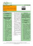
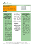
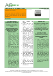
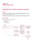
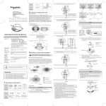
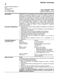
ACel-DT PIR – ULTRASONIC SENSOR
IP20
IMPORTANT NOTICE!
This device should be installed by a qualified
electrician in accordance with the latest edition of
the IEE Wiring Regulations and any applicable
Regulations.
User Manual
Operation
The presence detector
1324009508 integrates advanced
PIR
and Ultrasonic technologies in
one unit. The combination of
these
technologies helps to eliminate
false triggering problems even
in difficult applications. It is
suitable for indoor application
which is ideal for using in open
plan office, multi-stall public
restroom, conference room,
under-ground parking lots,
classroom, library, etc.
By using the knobs on
1324009508 or the IR remote
control 1324009524 (Accessory),
the time, ultrasonic sensor
sensitivity, lux, sens. function
(compensation for air flow)
and triggering method can be
adjusted.
Function
The presence detector has an
integrated light sensor that
ensures, lighting is only
switched on when it detects
movement and the daylight
level (lux level) is below the
preset level.
The light stays on as long as
movement is detected, and the
off-delay ensures that the
light remains switched On for
a period after the last detected
movement.
The presence detector can be It’s recommended that the detector is
used with its factory settings,
mounted on the ceiling. If
or the settings can be modithe detector is mounted suspended
fied using the remote control
from the ceiling the ultrasonic
– IR Remote 1324009524
range is decreased.
(accessory).
It is also possible to switch
Location:
the light On / Off with a push
The recommended installation
button.
height of this detector is 2 - 3m,
The push button will switch
and 2.5m is the optimal mounting
On the light regardless the lux
height. The detection range of
level.
PIR sensor can reach up to ø8m, and
When the light is switch On
ultrasonic sensor is an oval
with the push button, it stays
shape of 8m x 10m with small
On as
movement (i.e. hand wave), and an
long as movement is detected oval shape of 10m x 16m with large
and the Time (off-delay) has
movement (i.e. walk).
not run out.
The detection angle is 360° for both
If the light is switch Off with
PIR and ultrasonic sensors.
the push button, it stays Off as
See Fig. 2.
long as movement is detected
and the off-delay has not run
Enlarging the detection range:
out.
By using the presence detector
13240095011 it is possible to
enlarge the detection range. It is
Installation
possible to connect up to 2 pcs.
Position:
1321009511 to
The detector responds to
one 1321009508, which will control
movement and heat in relation to
the load according to it’s settings.
its surroundings.
1321009511 has the same detection
Avoid positioning the detector
range as 1321009508
close to heat sources such as
To get complete coverage, when
cookers, electric radiators,
using more sensors, it is
ventilation systems or any moving
recommended to calculate with
objects, cause by air flow, etc.
approx. 20% overlap in the in
Also surfaces that are highly
ultrasonic detection range.
reflective, like large window or
See Fig. 3.
glass sections can cause unwanted
activation Fig. 1.
Main Office: ACelSHOP ApS, Lille Strandstraede 14, DK-1254 Copenhagen K, CVR. No. 28115067
ACelSHOP ApS, Unit 17, Premier Park Acheson Way Trafford Park Manchester M17 1GA Phone: 161 874 1486 Fax: 161 877 2013
E-mail:[email protected]
Installation:
Flush mount with a standard
junction box or surface mounted
by
using the surface mounting base.
When using the surface mounting
base, there are 7 pairs of fixing
holes with various distances from
41mm to 85mm.
NOTE:
The direction of the ultrasonic
sensor should aim to the main
detection area to achieve the best
detection coverage.
Connection:
See connection diagram
Fig. 4 – 6.
After connecting the detector to
power, it takes approx. 30sec for
the detector to warm up. During
this time the load will be switch
ON.
Hereafter the detector will run
according to it’s settings.
Limiting the detection range
of PIR sensor:
If the detection range is too
large, it can be reduced by
fitting the
enclosed lens mask.
It makes it possible to reduce
the maximum detection range
of Ø8 m to Ø6 m or Ø2 m and
the angle of 360° can be
reduced in
steps of 30°. Fig. 8.
Settings
The settings can be modified
on the knobs below the cover
or by using the IR Remote
1324009524 (accessory).
Factory setting, Fig. 7:
Lux: 100 lux
Time (Off-delay): 15 minutes
Meter: 80%, approx. 8 x 13
meter
Sens.: OFF
Trigger method: PIR+US
Lux:
Setting the lux level between
10 and 1000 lux. Indications
of 10, 100, 300 and 1000 are
approximately.
Time:
Setting the off-delay. This has
6 preset settings:
1, 5, 15 and 30 minutes as
well as Pulse (interval of 1
seconds On , 9 sec. Off) and
test setting.
Under test, Load will be
switched ON for 2 sec., every
time a movement is detected.
Meter:
Setting the detection range.
This has 4 preset settings:
“-“, min setting, which is
approximately 2 x 3 m,
4 x 6 m, 7 x 8 m
and “+”, max. setting, which
is approximately 10 x 16 m.
Sens.:
Turning the compensation for
air flow On or Off
Trigger method:
Setting the triggering method.
This has 4 preset settings:
PIR/US, PIR, US and
PIR+US. This setting is use to
select the desired detection
method.
IR Remote
Settings when using the IR
Remote 1321009524 (accessory):
On & Off:
By pressing the “On” button, load
will be switched On for 8 hrs.
It’s confirmed by the LED’s
which will be flashing.
The presence detector can be
returned to Auto mode by
pressing “On” again.
By pressing the “Off” button, load
will be switched Off for 8 hrs.
It’s confirmed by the LED’s
which will be flashing.
The presence detector can be
returned to Auto mode by pressing
“Off” again.
Lock & Unlock:
Press “unlock” to unlock the
presence detector, so that the
settings can be modified.
Press “lock” to lock the presence
detector, after the settings have
been made, to save the changed
setting.
For all settings the presence detector
must be unlocked, the
setting selected and the presence
detector locked again before
the setting is activated. If the
presence detector is not locked, it
will lock automatically after 2
minutes and any modified settings
will be saved.
Reset:
If pressing “reset” all setting made
by the IR Remote will be
deleted. The presence detector will
run according to the setting
made on the knobs.
Test:
Load will be switched ON for 2 sec.,
every time movement is detected.
Lux:
Fixed settings for 10, 30, 100, 400,
1000 lux and a user defined
lux value (Learn actual lux).
User-defined lux value works in the
range 10 – 1000 lux.
Press the button, Learn actual lux,
until the presence detector’s
red and green LED’s are flashing.
This means the presence
detector has enter into learning
mode. Learning time is 10sec.
If the “Learn actual lux” was
successfully, it’s confirmed by the
LED’s which goes On
Then presence detector returns to
Auto mode.
If “Learn actual lux” is out of the
range of 10 – 1000 lux, the LED’s
in the presence detector will, after
10sec, flash quickly for 5sec to
Main Office: ACelSHOP ApS, Lille Strandstraede 14, DK-1254 Copenhagen K, CVR. No. 28115067
ACelSHOP ApS, Unit 17, Premier Park Acheson Way Trafford Park Manchester M17 1GA Phone: 161 874 1486 Fax: 161 877 2013
E-mail:[email protected]
indicate that “Learn actual
lux” was unsuccessfully.
In that case the following
values will be used:
Lux level is above 1000 lux,
the presence detector will use
1000 lux as lux setting.
Lux level is below 10 lux, the
presence detector will use 10
lux as lux setting.
Memo:
The “Memo” button is uses to
store and duplicate the values
of
Time1 and Lux.
1. Press ”Unlock”, at the
sensors, where the setting
should be learned from (the
sensor must have setting
learned via IR-remote).
2. Press “Memo” for more
than 3 sec. to save the settings
(after 3 sec. the green LED
will flash, as an indication for
saved settings)
3. Press “Lock”
4. On the sensor, to which the
setting shall be transferred,
press “Unlock”
5. Press “Memo” (the green
LED will flash, as an
indication for saved settings)
6. Press “Lock”. Time 1 and
Lux are now transferred.
Time:
For setting the off-delay,
press Time 1 and then one of
the 6 preset settings: 1, 5, 15,
30 and 60 minutes as well as
Pulse
(interval of 1 seconds On ,
9 sec. Off).
US + and US -:
Press “US + or US - ” to set
the sensitivity of ultrasonic
sensor.
Each time one of the buttons
are pressed, the sensitivity of
The presence detector is
increase or decrease by 10%,
which is indicated by the
green LED flashing.
When the sensitivity of presence
detector is at its highest or
lowest level, the green LED stays
On for approx. 2sec.
The default sensitivity is 80%.
Sens.:
Press “Sens. On” or “Sens. Off”
to turn the compensation for air
flow On or Off
Trigger method:
Setting the triggering method.
Press the corresponding button:
PIR/US, PIR only, PIR+US or US
only.
This setting is use to select the
desired detection method.
Terminology
Trigger method:
PIR+US (PIR and US):
Where a defined detection or
detection of minor motion is
necessary, choose this triggering
method. It can also reduce
false triggering problem. For
example, a classroom, an openplan office, etc.
Load will turn on when both PIR
and Ultrasonic sensors detects
movement.
When load is On either PIR or
Ultrasonic detecting movement
will keep the load On.
US only or PIR/US (PIR or US):
When there is high level of minor
motion or obstacle (furniture
or partitions) existing in the
monitored space, or it is a multistall space. For example, a multistall public restroom, an office
with partitions, etc.
In PIR/US mode load will be
turned on when either PIR or
Ultrasonic sensors detects
movement.
In US only mode, load will be turned
on when Ultrasonic sensors
detects movement.
PIR only:
If the monitored space is free of
obstacle or has high level of
airflow or the detection area is
needed to be well specified.
For example, a small-scale office
with air-conditioning, a small
conference room, etc.
In PIR only mode, load will be
turned on when PIR sensors
detects movement.
The detector is equipped with 2
led’s, a red and a green.
The LED’s are used to indicate
wherever the movement was
detected by PIR or ultrasound.
Red LED indicates PIR and the
green indicates ultrasound.
Sens:
The sensitivity (Sens.) function is
used to reduce the sensitivity
against air flow.
Meter:
The meter setting is used to reduce
the sensitivity of the
ultrasonic detection range.
Time:
The time setting is used to set the
off-delay, before the load
switches OFF, after the last detected
movement.
Lux:
The lux setting is used to set the
light level, for when below, the
load can switch ON.
Main Office: ACelSHOP ApS, Lille Strandstraede 14, DK-1254 Copenhagen K, CVR. No. 28115067
ACelSHOP ApS, Unit 17, Premier Park Acheson Way Trafford Park Manchester M17 1GA Phone: 161 874 1486 Fax: 161 877 2013
E-mail:[email protected]
Trouble shooting
Problem:
Load does not turn on
Possible cause:
1. Incorrect wiring.
2. The ambient light level is too
high.
Proposed solution:
1. Refer to wiring diagrams (See
Fig. 4 - Fig. 6) and check if the
load is malfunctioned.
2. Check the set Lux value and
adjust it if necessary (to a
higher lux value).
Problem:
Load does not turn off
Possible cause:
1. Off delay time is too long.
2. Detector has false triggering.
3. Incorrect wiring.
Proposed solution :
1. Check the set off delay and
adjust it if necessary (to a lower
value).
2. Check for any objects, which
may cause false triggering and
remove them from the detectors
range.
3. Refer to wiring diagrams
(See Fig. 4 - Fig. 6).
Problem:
Red LED does not turn on
Possible cause:
1. PIR is not chose as the
triggering method.
2. The movement is out of the PIR
detection range.
3. The lens mask is used an it
covers the movement.
Proposed solution:
1. Choose PIR sensor as the
triggering method.
2. The movement should be in the
valid detection range (ø8m).
3. Remove or reposition the lens
mask
Problem:
Green LED does not turn on
Possible cause:
1. Ultrasonic sensor is not chose
as the triggering method.
2. The movement is out of the
detection range.
Proposed solution:
1. Choose ultrasonic sensor as the
triggering method.
2. The movement should be in the
valid detection range (10x16 m).
Problem:
False triggering
Possible cause:
There are heat sources, airflow,
highly reflective objects or any
objects which may be swayed in
the wind within the detection
range.
Proposed solution:
Avoid aiming the detector toward
any heat sources, such as
air conditioning, electric fans,
heaters or any highly reflective
surfaces. Make sure there are no
swaying objects within the
detection range.
NOTE:
Effects that might have influents
on ultrasonic detection:
Airflow:
Airflow can cause false triggering
of the ultrasonic sensor.
If air flow is thought to cause
false triggering, try setting the
Sens.
Knob to ON.
This function will reduce the
sensitivity of ultrasonic sensor
approx. 10% ~ 40% according to
the strength of the airflow.
Sound wave absorbing materials:
The sensitivity and range can be
affected by the materials such
as carpet, sound absorbable
materials, curtains, etc
Wiring:
A reverse connection in between N
and L will cause lower
sensitivity of ultrasonic sensor
sensitivity and also reduce the
detection range.
Technical data
Input:
Power supply ....230 V ± 10% 50 Hz
Power consumption ...................2 W
Output:
Relay contact
NO, 230 V, μ 10 A
potential free
Load Incandescent lamps .....2300 W
Fluorescent tubes, not
Compensated ......................1200 VA
Halogen incandescent lamps 2300 W
Energy-saving bulbs ........58 x 18 W
Max. compensation capacity .140 μF
Max. inrush current .......165 A/20 m
sec.
Performance:
Lux range.....................10 – 1000 lux
Time delay ......................1 – 30 min.
Detection range .........................360°
Ultrasonic .....0 x 16 meter (138 m2)
PIR ........................ø8 meter (50 m2)
Installation and ceiling height 2 - 3
meter
Protection degree .....................IP 20
Insulation class ........................CL. I
Ambient temperature ..0°C ... +45°C
Approvals:
CE according to .........EN 60669-2-1
Main Office: ACelSHOP ApS, Lille Strandstraede 14, DK-1254 Copenhagen K, CVR. No. 28115067
ACelSHOP ApS, Unit 17, Premier Park Acheson Way Trafford Park Manchester M17 1GA Phone: 161 874 1486 Fax: 161 877 2013
E-mail:[email protected]
Dimensions for ACel-DT PIR
Installation for ACel-DT PIR
Location for ACel-DT PIR
Main Office: ACelSHOP ApS, Lille Strandstraede 14, DK-1254 Copenhagen K, CVR. No. 28115067
ACelSHOP ApS, Unit 17, Premier Park Acheson Way Trafford Park Manchester M17 1GA Phone: 161 874 1486 Fax: 161 877 2013
E-mail:[email protected]
Enlarging the detection range + diagram for ACel-DT PIR
Diagram for ACel-DT PIR Master + Slave
Diagram for ACel-DT PIR Master + HVAC and factory setting
Main Office: ACelSHOP ApS, Lille Strandstraede 14, DK-1254 Copenhagen K, CVR. No. 28115067
ACelSHOP ApS, Unit 17, Premier Park Acheson Way Trafford Park Manchester M17 1GA Phone: 161 874 1486 Fax: 161 877 2013
E-mail:[email protected]
Limiting the detection range of ACel-DT PIR
Main Office: ACelSHOP ApS, Lille Strandstraede 14, DK-1254 Copenhagen K, CVR. No. 28115067
ACelSHOP ApS, Unit 17, Premier Park Acheson Way Trafford Park Manchester M17 1GA Phone: 161 874 1486 Fax: 161 877 2013
E-mail:[email protected]