1
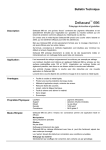
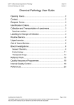
USER MANUAL ACel800
ACelTIMER IP66
IMPORTANT NOTICE!
This device should be installed by a qualified
electrician in accordance with the latest edition of
the IEE Wiring Regulations and any applicable
Regulations.
Installation
ACEL800 IP66 Weatherproof
(5 sec-20 min)
6.
Installation of Single Time
Switch
PLEASE ENSURE MAINS
POWER IS SWITCHED OFF
BEFORE ANY TIMER
INSTALLATION
1. Mount
2.
3.
4.
5.
the
IP66
Weatherproof box to your
surface using either the
four screw holes in each
corner or the 2 hole
mounting bracket. If
using
the
mounting
bracket
once
secure
please
clip
the
Weatherproof box into
place.
When installing the cable
into the Weatherproof
box it is advisable to use
an IP68 Cable Gland
( Not Supplied ).
Install power to the Timer
Switch ensuring that you
have the correct wires in
both the Live IN & Live
OUT terminals.
The LED will illuminate
immediately once the
mains power is switched
back on.
If the LED does not
illuminate your light
fittings
or
heating
appliance will be on, if
this happens please
7.
8.
9.
10.
follow step 4, if the LED
is on then follow step 7.
Press the small RED reset
spring on top of the
ORANGE relay switch
using the edge of your
electrical
screwdriver
blade, once this has been
done the light fittings or
heating appliance will
switch off and the LED
on the time switch will
illuminate.
You are now ready to set
your time level required,
using
the
BLACK
potentiometer ( BLACK
TURN SCREW ) with
your screwdriver set your
time level as required.
Place the switch back
plate into position on the
Weatherproof back box
and clip the timer switch
plate
into
position
ensuring the LED lines up
with the LED hole on the
plate.
Attach the Weatherproof
Face plate & screw into
position.
The timer is now installed
& ready to use.
Important Note
Once the timer is installed and the
timing is set, please allow a
minimum of 3 second intervals
between the light fittings or
heating appliance timing out and
switching the timer switch back
on.
ACEL800 IP66 Weatherproof
(5 sec-20 min)
Installation of Multiple Time
Switches
1. After
Multiple
Time
Switches are installed and
the power is switched back
on, if the lights or heating
appliance come on then one
or more of the installed
Time Switches will need to
be reset using the small
RED RESET spring as
above in step 4.
2. Please do this on all of the
Time Switches one by one
until the light fittings or
heating appliance have gone
off and the LED's on the
Time Switches illuminate.
3. Once all the LED's are
illuminated you are now
ready to set the time level
required on each Time
Switch as above in step 7 &
complete installation as
above in steps 8, 9 & 10.
Main Office: ACelSHOP ApS, Lille Strandstraede 14, DK-1254 Copenhagen K, CVR. No. 28115067
ACelSHOP ApS, Unit 17, Premier Park Acheson Way Trafford Park Manchester M17 1GA Phone: 161 874 1486 Fax: 161 877 2013
E-mail:[email protected]
Fig 1:
Fig 2:
Fig 3:
Fig 4:
Fig 5:
Fig 6:
Fig 7:
Fig 8:
Fig 9:
Fig 10:
Main Office: ACelSHOP ApS, Lille Strandstraede 14, DK-1254 Copenhagen K, CVR. No. 28115067
ACelSHOP ApS, Unit 17, Premier Park Acheson Way Trafford Park Manchester M17 1GA Phone: 161 874 1486 Fax: 161 877 2013
E-mail:[email protected]
Wiring diagram for all ACelTIMERS
Main Office: ACelSHOP ApS, Lille Strandstraede 14, DK-1254 Copenhagen K, CVR. No. 28115067
ACelSHOP ApS, Unit 17, Premier Park Acheson Way Trafford Park Manchester M17 1GA Phone: 161 874 1486 Fax: 161 877 2013
E-mail:[email protected]
Wiring diagram for ACel600, ACel605, ACel800, ACel805, ACel810, ACel815
Main Office: ACelSHOP ApS, Lille Strandstraede 14, DK-1254 Copenhagen K, CVR. No. 28115067
ACelSHOP ApS, Unit 17, Premier Park Acheson Way Trafford Park Manchester M17 1GA Phone: 161 874 1486 Fax: 161 877 2013
E-mail:[email protected]