1
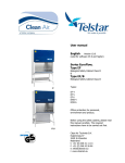
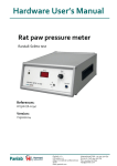
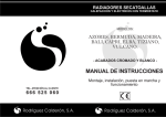
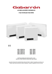
Microbiological Safety Cabinet class II EN 12469 certified by TÜV
USER MANUAL
Serial number:
Date of delivery:
Customer:
Kojair Tech Oy
Teollisuustie 3
FINLAND
Tel. +358 3 471 7000
Fax +358 3 471 7077
[email protected]
www.kojair.com
The definition of the Microbiological Safety Cabinet is as follows:
A ventilated enclosure intended to offer protection to the user and environment from the aerosols
arising from the handling of potentially hazardous and hazardous micro-organisms, with discharge to
the atmosphere being filtered.
You are owner of one of the most modern and silent Class II Microbiological Safety Cabinets
available. The Golden Line –series is microprocessor-controlled and therewith widely customizable.
All the standard-configurations of Golden Line series are type-tested and approved by TÜV
Rheinland according to current EN –standard 12469:2000 (the standard for Biosafety cabinets)
NOTICE! Only use this product for its intended purpose.
rev.3.01
1.
2.
3.
FEATURES AND SAFETY ........................................................................................ 4
1.1.
Introduction to the cabinet .................................................................................. 4
1.2.
Construction materials ....................................................................................... 5
1.3.
Positioning the cabinet and safety instructions .................................................. 5
USING THE CABINET ............................................................................................... 7
2.1.
Control panel ...................................................................................................... 7
2.2.
What to do at first start-up .................................................................................. 9
2.3.
Control panel functions .................................................................................... 10
5.3.1
User settings..................................................................................................... 11
2.4.
Daily maintenance and cleaning ...................................................................... 12
WARRANTY ............................................................................................................ 15
3
rev.3.01
1. FEATURES AND SAFETY
1.1.
INTRODUCTION TO THE CABINET
Microbiological safety cabinets are intended to reduce the risk to the operator when handling hazardous
or potentially hazardous micro-organisms. They do not necessarily protect the operator from all the
hazards involved. Some types of cabinet can also protect the materials being handled in them from the
environmental contamination.
BioWizard Golden Line is a Class II Microbiological Safety Cabinet operating on the recirculation
principle. It protects the products handled on the work surface from contamination and safeguards the
operator against substances hazardous to health.
Picture 1. BioWizard Golden Line Class II Safety Cabinet
Examples of the uses of the cabinet are cellular culture, handling pathogenic microorganisms, isotopes, sterile work for operations, handling medical substances in hospitals and
pharmacies as well as the production and maintenance of electronic items in which particle-free air is a
necessity.
NOTE! Only Class III Microbiological Safety Cabinets can be used for working
with Group 4 pathogens. The Kojair Biowizard BW3 is a class III safety cabinet
which protects the user and the environment from Group 4 pathogens.
Please contact your local Kojair representative for more information.
4
rev.3.01
The basic principle of the cabinet is that the replacement air moves through the grid at the front edge of
the work surface to the bottom basin and then again to the recirculation system. Simultaneously it forms
an air curtain in the work opening, which prevents air from flowing outwards.
The recirculating air inside the cabinet is purified as it flows through the HEPA-filter and it flows
laminarly through the workspace. (see picture 2).
Picture 2. Principle of the airflow
1.2.
CONSTRUCTION MATERIALS
The main construction material of the cabinet is painted mild steel. The work surface and the collecting
pan located below it are made of stainless steel (AISI 304).
The front and side walls are made of 6 mm thick laminated safety glass.
1.3.
POSITIONING THE CABINET AND SAFETY INSTRUCTIONS
The cabinet should be positioned so that there are no external or conflicting airflow disturbances when it
is operating such as open windows or personnel passing in front of it.
The cabinet should be switched on at least 15 minutes before starting the work so there is time to clean
the workspace. Before starting the actual work it is recommended that the work is carefully prepared so
that equipment and material are moved in and out of the cabinet as little as possible.
A continuous in-and-out movement disturbs the airflow and weakens the protection given by the cabinet.
For the cabinet to give the best possible protection, you should try to minimize rapid hand and arm
movements as much as possible.
NOTE! Beware that you do not obstruct the airflow by obstructing the grid on
the worktable. The safe working area is between the grids (see picture 3.).
5
rev.3.01
Picture 3. Safe working area.
While you are working, the front glass of the cabinet should be in the working position. If the front glass
is not in the correct position, the user will hear immediate warning from the alarm. If you intend to switch
off the cabinet when you have finished working, it is better to close the front window before shutting
down the cabinet.
However, it is better if the cabinet can always be in the normal operating
mode. When you are not working in the cabinet, close the front glass and
device automatically switches to half speed mode. See chapter, 2.1 Control
panel.
It is strongly recommended that gas flames are used on the left side of the work space as short time as
possible. That is because the flame can disturb the airflow and it will warm up the recirculating air, which
can cause an alarm.
NOTE! Before starting work, check that HEPA-filter on the roof of the
workspace is intact.
6
rev.3.01
2. USING THE CABINET
2.1.
CONTROL PANEL
CONTOL PANEL
CONTOL BUTTON / ALARM LED
FUNCTIONAL DESCRIPTION
Red led is used for indicating alarms. When the fan has been
switched on the general alarm -LED lights up. The general alarm LED lights stays on until the air speed is sufficient. If sufficient air
speed is not reached in 5 minutes, the cabinet gives an acoustic
alarm.
1.
Alarm indicators
Working in the cabinet is not allowed while the visual and/or
acoustic alarm is activated.
If the power failure occurs the general alarm LED –lights up and the
acoustic alarm will sound. Working in the cabinet is not allowed
during power failure.
1. A
Exhaust air alarm
1. B
Recirculating air alarm
1. C
The front window wrong position
2.
Alarm resetting button
If the exhaust air speed is not correct the general alarm –LED and
the exhaust air alarm –LED will light up and the acoustic alarm will
sound.
If the recirculating air speed is not correct the general alarm –LED
and the recirculating air alarm –LED will light up and the acoustic
alarm will sound.
The front glass of the cabinet should be in the working position
during the work. If the front window is not in the correct position
both the general alarm –LED and the front window alarm –LED will
light up and the acoustic alarm will sound.
Not in use in this cabinet model
7
rev.3.01
3.
Start button
4.
Lights
5.
Socket
6.
Front window up
7.
Lcd –display
8.
Mode
9.
+
10.
General alarm
Press this button to start the cabinet. (Press for few seconds to
start)
You can switch on workspace lights on using this button.
This button activates the socket.
You can move up the front window using this button
With this button you can browse through menus and set values
Red led is used for indicating alarms. When the fan has been
switched on the general alarm -LED lights up. The general alarm LED lights stays on until the air speed is sufficient. If sufficient air
speed is not reached in 5 minutes, the cabinet gives an acoustic
alarm.
Working in the cabinet is not allowed while the visual and/or
acoustic alarm is activated.
11.
Start / switch cabinet to half speed mode
You can switch cabinet to half speed mode using this button. The
workspace lighting will shut down and the cabinet will give an
acoustic and visual alarm. The acoustic alarm signal lasts for only a
few seconds.
The UV-light socket is in the workspace back wall; if you wish to use
the UV-light, push the UV-light button on the control panel.
There are two modes for UV-light, button or timer.
12.
Uv –light (option)
If button is selected, the UV-light will stay on until UV-button is
pressed again. If timer is selected, the cabinet asks for shutdown
time, which is selectable between 20 ... 120 min with 10 min
interval. Time can be changed with + and - buttons and time is
selected with SET button. UV-light is switched off after selected
time.
14.
Front window down
Used with optional gas valve. If you use liquid gas during the
procedure, first you have to push the magnetic valve button from
the control panel. This enables the gas to flow.
The gas valve works only when the cabinet is at half speed mode.
You can move down the front window using this button
15.
Set
With this button you can confirm selection.
16.
-
With this button you can browse through menus and set values
13
Magnetic valve
8
rev.3.01
2.2.
WHAT TO DO AT FIRST START-UP
NOTE! Before using the cabinet, perform the installation tests (listed in
chapter –Testing in service manual) and clean the cabinet carefully. See the
cleaning instructions in section 2.4 Daily maintenance and cleaning
Check if the cabinet’s power cable is in the socket outlet (230 VAC, 50 Hz) and the other lead is in the
electric plug on the top of the cabinet.
Turn the mains on by the key-switch (located on the right side of the front panel, see picture 4.). The
self-test can take 1 to 5 minutes and during the self-test the cabinet does not take any orders. During
self-test the red general alarm -LED lights up, other led’s blink and cabinet gives an acoustic alarm
(acoustic alarm lasts only a few seconds). Do not touch the controls during the self-test.
Picture 4. Key-switch
The fan and the lights can be switched on by the pushbuttons located in the control panel. Before
switching the fan on you should check that the outlet on the roof of the cabinet is not blocked so that the
filtered exhaust air can be freely exhausted out of the cabinet.
Æ TO START UP CABINET PUSH BUTTON 3. (Press for few seconds to start)
If sufficient air speed is not reached in 5 minutes, the cabinet gives an acoustic alarm.
The key lock is activated by pressing SET -button and START -button in sequence. When the key lock
is activated the panel can be safely wiped, etc. without risking unwanted commands. Green led’s in the
front window up and front window down –buttons are blinking to indicate lock mode. The setting can be
deactivated by pressing the SET -button and START –button in sequence.
.
9
rev.3.01
2.3.
CONTROL PANEL FUNCTIONS
The diagram below represents the hierarchy on menu options available in Biowizard Golden Line
cabinet. Press MODE button to enter menu. At first there is a selection user/service with - / + buttons.
Service level requires password. Only Kojair Tech Oy authorized service technician is allowed to access
service level.
10
rev.3.01
2.3.1
USER SETTINGS
Functions under the user settings are for “daily use” and using these functions
doesn’t harm protection level of the cabinet, that ´s why you do not have to set any password to get
access to them. All the text in LCD-display is shown with capital letters and texts can be shown with six
different languages (see table below)
Start the cabinet by the main key switch. The LCD-display shows the current software version of
controls and the cabinet also begins a self-test.
MODE – opens the menu and you can browse it by using + and - buttons
SET – allows you to select a function from the menu and / or confirm selection.
Press button 8. MODE
Display shows: +
=SERVICE
Select USER level with
-
=USER
“-“
By pressing – and + buttons the user can scroll through the functions. A function is selected by pressing
button SET button.
User setting functions are described in the table below
USER SETTING
FUNCTION
SET LIGHT LEVEL
DESCRIPTION
Regulates the intensity in the working area between 60 % and 100 %. By pressing the
[+] or [-] -buttons the display shows the value in 1% intervals. To confirm the desired
value press SET –button. The light intensity changes when the SET –button is
pressed.
Select first the function set or browse.
SET UV TIMER
SET SOCKET TIMER
In set mode you can select daily or weekly mode. In daily mode you select start and
end times with [+/-] buttons. The function is selected by pressing SET. In weekly
mode you select first the day with [+/-] buttons, accept it with SET button and select
finally the start and end times like in daily mode. Exit with MODE button. If you want
to delete timer settings, see below.
In read mode you can check or reset the timer settings. The display shows first the
weekly settings, with next step down [-] you can move in settings, mode button reset
the timing. The display shows “Deleted…” after every deleted timing and when all
timings have been reseted, the display shows “Empty”. After that you can make the
same with daily settings. With SET –button you can go back if do not want to delete
timer settings.
SHOW UV LIGHT AGE
The display shows how long time the UV-light has been on.
RESET UV AGE
Resets the hour counter for the UV-light.
FAN RUNNING TIME
This function shows the time the fan has been running.
11
rev.3.01
SET LIMIT VALUES
FAN 1/1 SPEED
Set the alarm limits to the fan and UV-light. The limit can be selected between
2000 - 10000h for fan and 1000 – 10000 for UV-light.
Shows the rotation speed of the fan to normal operation speed or ½ speed. The
current speed, which is between 0-100 % for 1/1 speed and 0 – 50% for ½ speed, is
seen on the display.
FAN 1/ 2 SPEED
NOTE! The values can’t be changed.
Set the clock to real-time. Change the value with +/- buttons, with SET button to the
next field/ok.
HH:MM YYYY MO/DD WD
SET TIME
HH=hours MM=minutes
MO=month DD=day
SET LANGUAGES
2.4.
YYYY=year
WD=day of the week
Selects the language: English, Swedish, German, Finnish, French, Dutch
DAILY MAINTENANCE AND CLEANING
NOTE! Before maintenance and cleaning it is mandatory always to check what
kind of substances have been handled in the cabinet. If cytostatics or other
hazardous substances have been handled in the cabinet special care has to be
taken. The person who is cleaning and servicing the cabinet should use a
mask, protective gloves and an overall. More detailed instructions will be
issued by the person in charge of the laboratory.
Switch the main-key switch on. The switch is located on the right bottom-edge of the front panel.
Move the front window to lowest position and remove the cover plates of the lights. Pull the quick latch
down and slightly open the front panel. Lift the cover plate slightly and pull it out at the same time. Then
do the same to the other cover plate (picture 5.). In order to clean the back of the front window you have
to lift it up carefully (picture 6c). After cleaning put the cover plates back to their places.
12
rev.3.01
Picture 5. Removal of light cover plates
NOTE! Do not clean front glass with detergents or desinfectances around
glass plate (see picture below.)
13
rev.3.01
NOTE! Handle the front window with extra care. See pictures 6a, 6b and 6c.
Picture 6a. Cleaning
the bottom
sink.
Picture 6b. Cleaning
the bottom of the
worktop.
Picture 6c. Cleaning
from inside of the
window.
Clean the workspace of the cabinet with mild detergents and desinfectance with a 70 % alcohol solution.
You can wipe off the alcohol that has been sprayed on or you can simply let it evaporate.
The cabinet’s outer surfaces should be cleaned by wiping with neutral or mild base detergent solutions.
NOTE! The use of dissolvents for cleaning is not permitted.
Clean the work surface inside the cabinet. The lower surface and collecting pan should always be wiped
during cleaning (Pictures 6a and 6b).
NOTE! When cleaning the workspace of the cabinet you should be careful
about the filter located above the workspace and also the sensor of the down
flow indicator in the back wall of the workspace. They can be easily damaged
when wiping the cabinet and therefore should not be touched.
You can also use the UV-light (option) for decontaminating the workspace; it takes 30 to 60 minutes.
You can use the timer for timing the decontamination (see chapter 6.1 Decontamination in service
manual).
UV-light must not be switched on when working in the same room. UV-radiation can harm eyes and skin
of operators and cause damages to other materials.
NOTE! UV-light is not recommended for decontamination by the EN 12469.
Normally the cabinet requires only cleaning and changing the filters when necessary. The filter change
requires special knowledge and is done by service technicians trained by Kojair Tech Oy
14
rev.3.01
3. WARRANTY
The manufacturer of this product provides a guarantee under the following
terms:
•
The duration of this guarantee is one (1) year from delivery or from approved
handover, when no other delivery term has been agreed.
•
The guarantee covers manufacturing, raw material and material defects. The
customer is to inform the manufacturer of any defects without delay.
•
The guarantee does not cover wear and tear components such as filters or
fluorescent light tubes.
•
The guarantee is not valid any more if this device is used for any other use other than its designed
use or if any harmful substance is used, which damages the cabinet material.
•
The guarantee is not valid any more if any other spare part is used in replacement of original
components as listed in the spare parts list. In connection with the guarantee the manufacturer
reserves the right to obtain any damaged component. If such damaged component is not returned
to the manufacturer during the duration of the guarantee then the manufacturer reserves the right to
invoice for replacement components.
•
•
•
This guarantee includes repair work carried out by the manufacturer, as well as
required replacement parts under guarantee.
The guarantee is not valid any more if this cabinet is repaired or serviced, during the valid
guarantee period, by persons other than personnel from the manufacturer or persons authorized by
the manufacturer.
15