1
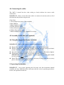
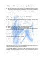
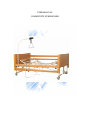
USER MANUAL
COMMUNITY NURSING BED
CONTENTS
Section Description
1. General Safety Instructions
2. Features
3. Installation
4. Assembly
4.1 Assembly of sleeping platform
4.2 Assembly of the end frames
4.3 Attaching the end frames to the sleeping platform
4.4 Connecting the cables
4.5 Assembly of the side rails (optional)
4.6 Using the integral bed frame extension
5 Operation Instructions
5.1 Operation of the height adjustment and profiling functions
5.2 The locking system of the handset
6 Additional Safety information
7 Maintenance and care
8 Storage
9 Troubleshooting
10 IP66 Ingress Protection
Page No.
3
4
4
4
4
5
5
6
6
6
6
7
7
7
8
8
9
10
1. General Safety Instructions
Before putting this Community Nursing bed into operation, it is very important
that this Instruction Manual is read carefully, as the manual contains important
information for the safe and proper use of the bed. Please keep this manual handy
for future reference.
All of the functions of this bed should be full tested by a competent person before
the bed is used.
The bed must not be used if faults have been detected on it that may injure the
patient, staff, a third person, or damage the bed or the surrounding interior
The bed may only be used by persons who, by their knowledge, training or
practical experience, provide a guarantee that the bed shall be used in a safe and
correct manner
The operating persons are obliged to acquaint the patient lying on the bed with
the control functions that are designed for use by the patient, and their safe usage
The operating person is obliged, before using the bed, to be confident of the
functionality and safe usage of the bed
The bed may be used only on oven and solid floors
The bed must not be overloaded even for a brief period
If there is a patient on the bed, the castors must be locked (with the exception of
when traveling with the bed) – an unlocked bed poses a risk of injury to the
patient when leaving the bed or when supporting themselves
The height of the mattress platform must be adjusted according to the height and
condition of the patient
No other people my sit on the bed
When handling the mobile parts of the bed, care must be taken that the patient,
other people or objects do not become trapped during its movement
Before cleaning or maintaining the bed, the supply cable must be disconnected
from the mains
The bed should not be used were there is a danger of explosion or in the presence
of inflammable anesthetics
When maintaining and cleaning the bed in the space between the undercarriage
and mattress platform, the adjustment functions on the handset must be locked so
there is no accident due to any unintentional activation and subsequent downward
movement of the mattress platform
The mains cable must be placed in a way so it does not get wound round the
mobile parts or trapped between them. If the mains cable is damaged there is a
serious danger of injury from electrical current
An inspection should be made at least once a month for visible wear and tear of
all mobile parts and cables
The bed is intended for adults from 12 years of age. Ensure that children only
have access to the bed under adequate supervision. Do not allow children
underneath the bed while it is in operation
This modular nursing bed has four electrically powered functions – back, know
break and height adjustment
2. Features
The drives for the adjustment functions consist of electric mechanical linear
motors with maintenance free permanent lubrication
The motors are operated by a handset, which is connected to the main control box
via a spiral wound cable.
The motors and handset are isolated from mains voltage (230v) and operated at
DC 24v low voltage
3. Installation
The Community Nursing Bed should only be assembled by a suitably competent
person. They must read and fully understand all of the instructions contained in this
manual. Do not attempt to assemble this bed if you are unsure about any part of the
instructions or any damage of defect can be identified.
The fuse in the electrical mains plug should not exceed 5 amps
The bed should be located n a level flat surface
Do not site the bed on loose carpet, rugs or floor coverings.
The cable from the mains 230v power supply plug to the main control unit must be
positioned clear of the lift mechanism (to eliminate the danger of shearing or crushing)
and also clear of the braked castors.
4. Assembly
4.1 Assembly of the’ sleeping platform’
Slide the side frames together as indicted in the diagram
Ensure both frames fit fully together until the outer tubes touch each other and the
holes in the bed frame match up with the holes in the connecting bar.
Insert the lock-pins and tighten the hand-screws on the underside on each side of
the side frames. Do not over tighten.
4.2 Assembly of the end frames
Firstly fit the 2 longer ‘T’ brackets onto one of the ‘end frames’
This will now be used as the ‘foot frame’
Secondly fit the 2 shorter ‘T’brackets onto the other ‘ end frame’
This will now be used as the ‘head frame’.
NOTE: You must decide to use either the high position or low position screw holes on
the head and foot frames before assembly.
IMPORTATN- The bracket positions on the end frames must be at the same level on
all 4 xxxxx locations.
4.3 Attaching the end frames to the sleeping platform
Once assembled, the ‘end frames’ can be fitted onto the ‘sleeping platform’
Firstly identify the ‘head’ and ‘ foot’ ends of the ‘sleeping platform’
The head end has one mesh section and foot end has two sections.
IMPORT – For safe use, the head and foot frames must be fitted to the correct ends of
the sleeping platform.
Ensure the ‘T’ bracket of the ‘head & foot frames’ fits fully into the side frames
of the ‘ sleeping platform’
Check that the hole in the side frames matches up to the hole in the T bracket,
before inserting the ‘ lock-pins’
Tighten the ‘hand-screws’ on the underside of both sides of the side frames. Do
not over tighten.
Attaching the Foot Frame
IMPORTANT – Please make sure that for normal use, the longer T bracket is fully
inserted into the side frames before inserting the lock-pins.
The second sets of fixings are only to be used to extend the bed length when an
extension panel must be used.
4.4 Connecting the cables
The ‘MCL 3 control box has color coding to clearly indicate the correct cable
connections.
IMPORTANT – Please ensure all of the cables are connected correctly and test all of
the functions fully before using the bed
Color Code
1. Green Supervisor device. (Not available)
2. Red: Handset
3. Black: Backrest motor
4. Yellow: Footrest motor
5. Silver: Head raise-up motor
6. White: Foot raise-up motor
7. Black: Backup battery plug. (Optional accessory)
4.5 Assembly of the side rails (optional)
4.6 Using the integral bed frame extension
IMPORTANT – The bed must only be extended at the foot end
Remove the ‘lock-pins’ and loosen the ‘hand-crews’ on the ‘foot frame’
Pull the ‘foot frame’ out from the ‘sleeping platform’ until the second set of holes
on the ‘T’ brackets matches the fixing holes on the side frame.
Insert the ‘lock-pins’ and tighten ‘hand-screws’ on both sides. Do not over tighten
Fit the mesh ‘extension panel’ on top of the extended ‘T’ bracket
IMPORTANT – If the bed is extended, only the approved extension panel should
be used, and this must be fitted.
Noted: The extension panel is an optional accessory. If you require this accessory
please contact our local supplier or dealer
5. Operating Instructions
IMPORTANT – Any person operating this bed must read this instruction manual
carefully and they should be fully conversant with the correct operating procedures
for the safe operation of this bed.
5.1 Operation of the height adjustment and profiling functions
The head section, knee break, bed height and Trendelenberg titling are adjusted
by pressing the appropriate button on the handset. For ease of sue the buttons are
labeled graphically according to their function (please see photograph)
WARNING ! – Do not exceed the maximum usage period – all function maximum of
6 minutes per hour (10%)
5.2 Locking system of the handset (Model: IPROXX SE)
The handset provides a locking function to avoid a potentially dangerous lifting
operation. Touching the handset with the ‘magnet key’ will release the locked
functions.
When the LED light is unfit. The handset is locked for all functions.
When the LED light is on ‘green’. The handset has all functions except
Trendelenberg titling function.
When the LED light is on ‘orange’. The handset has all function.
Note : The initial setting for handset is a Locked condition
The handset will resume locked condition with the LED unit when there
has been no further operation within 30 seconds.
The handset will resume locked condition with the LED unit after a power
failure or interruption of power supply.
WARNING! – Using Trendelenberg titling can be extremely dangerous for some
users. You must ensure that the Trendelenberg tilting will not have any adverse effect
on the user before allowing any tilting operation.
6. Additional Safety Information
All persons assembling or using the bed should have read the user manual and
familiarized themselves with its operation.
Ensure that any objects such as waste paper baskets, occasional tapes, chairs etc are
not placed underneath the lifting mechanism of the bed.
To avoid injury, no limbs or body parts of either the occupant or carrier must be
protruding from the bed between the side rails or into the mechanism of the bed
during operation of powered functions.
Before moving the bed to a different location, remove the electrical plug from the
230v mains supply power socket. Failure to do so may result in damage to the bed or
fatal injury.
When moving the bed with occupant in situ, the bed should not be pushed over a
threshold strip of more than 2 cm maximum height.
Under no circumstances must the bed be moved by pulling or pushing the side rails
eight when the bed is occupied or empty. They are not designed for this purpose.
Never exceed the maximum usage period of 6 minutes per hour for the electrically
driven bed functions, by lengthy and unnecessary profiling or height adjustments.
This can trip the thermal safety fuse, which will stop all powered movement of the
bed parts.
Once the bed is sited in the desired position, always ensure that the castors are locked
in the braked position. (see illustration)
Before dismantling or troubleshooting
Ensure that all functions are in the lowered position (where possible), the power
supply is switched off and the power cable is disconnected fro the mains by
un-plugging. Ensure that all functions are not under any undue load and are free
moving.
Before operation
Ensure that the assembly is completed fully and in accordance with the
instructions given in the user manual.
Ensure that the local electrical mains supply voltage corresponds to that marked
on the main control unit label before connecting to the mains supply.
Ensure that cables from all motors are connected to the main control unit
correctly before operation.
Ensure that all functions of the bed have been tested and that the bed is working
normally.
IMPORTANT – In the case of any unusual noises or smells during the operation,
immediately switch the power off at the minas and remove the mains plug from the
power socket.
Ensure that no cable are trapped in the mechanism or are damaged.
IMPORTANT – If you have any doubts concerning that safe operation of this bed, do
not sue the bed and call your local supplier or dealer.
7. Maintenance and care
To clean the powder coated tubular sections and wooden parts use a damp cloth with
normal household cleaners or warm soapy water.
Do not use any cleaning agents containing ammonia, abrasives or strong solvents.
This will lead to damage of the powder coated finish on metal parts and the finish on
the wooden parts.
Mechanical cleaning, scouring, high-pressure hoses or automated cleaning will
damage the bed.
All moving parts on this appliance are fitted with maintenance free self lubricating
bearings and should not be oiled or greased.
All motors, cables and mechanical functions must be check by a suitably qualified
service engineer for damage and correct operation, at least once every twelve months.
8. Storage / Transport Frame
To prevent damage to the Community Nursing Bed or any components during storage
or transportation, you should always use the Storage / Transport frame (which is
supplied as standard). To use this please follow the following steps.
Disconnect the power plug and carefully roll up the power lead ensuring no links.
Disconnect all of the internal cables and store them securely
Remove the lock-pins from the centre of the sleeping platform and loosen the
hand screws.
Separate the two sleeping platform pieces in the middle
Remove the lock-pins from the ends of the sleeping platform and loosen the hand
screws.
Separate the sleeping platform pieces from the end frames.
Fit the transport frames between the two bed ends as shown in the drawings
The two sleeping platform pieces should be carefully placed onto the storage
frame with the actuators located in the middle as shown in the drawings, taking
care not to damage any components
The lock-pins and hand screws must be installed and tightened to ensure secure
and rigid fixing of the sleeping platform pieces during transportation or storage
The bed should only be rolled across smooth hard surfaces. Any movement across
rough or uneven flooring could cause damage to the castors.
Store in a dry place (between + 5 ℃ and + 45 ℃ )
The relative humidity of the air should be between 30% and 70%.
Store all removed parts together in one place (or mark them if necessary ) to
avoid mixing them up with other products when re-assembling
Components must be stored without being subjected to strains
IMPORTANT – When re-assembling the bed all assembly procedures and safety
checks much be performed as described in this Instruction Manual
9. Troubleshooting
Q1: Motors not working when handset operated
Ans: Check the connection to mains (when
electric power supply is being used)
Check the handset and main control box
connections
Q2: One motor does not work when the button
is pressed.
Ans: Check the connection between working
cable and control box.
Q3: A ‘Be’ sound is heard when the button is
pressed.
Ans: The ‘backup battery’ (optional accessory
) has low battery power.
Plug the mains power cable into a power
socket
Q4: Handset or motors do not function.
Ans: A) No power supply --- Connect to mains.
B) Handset or motor defective -----Contact
your local supplier or dealer.
Q5: Motors suddenly have no response or
movement
Ans: 1) Unplug the mains cable, and plug back
in.
2) Leave the system in the rest position for
approx. 20 -30 min.
3) Contact your local supplier or dealer.
Q6: Permanent or longer sounding warning
signal
Ans: Contact your local supplier or dealer
Q7: Handset LED lights up in locked state or
does not light up in un-locked state
Ans: Contact your local supplier or dealer
Q8: No adjustment can be made by handset
Ans: 1) Try using the magnet key to release the
locking function
2) Check the handset connections
3) Contact your local supplier or dealer
WARNING !!
Any unauthorized modifications, adjustments or alterations will result in warrant
invalidation.
Repairs should only be carried out by a suitably quilted competent engineer.
10. IP 66- Ingress Protection
The Community Nursing bed offers IP66 Ingress Protection on all electrical
components and controls, as standard. This is a very high level of protection which is
completely dustproof and capable of being washed by a lot of water, without affecting
the electrical operation of the bed
WARNING! The bed must be disconnected from the mains supply before any kind of
washing procedure is undertaken.
This bed and components are not suitable for steam cleaning or the use of aggressive
chemical cleaners. If in any doubt about a cleaning method or materials, please check
with your local supplier or dealer before cleaning.
Industrivej 23 – 8800 Viborg, Denmark
Tel. + 4586613611 Fax. +45 86613911
E-mail: [email protected]
www.chiroform.dk