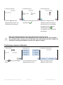
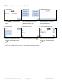
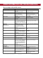
1
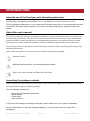
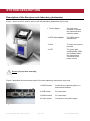
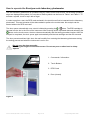
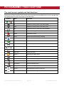
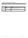
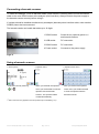
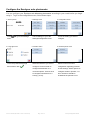
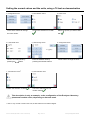
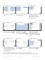
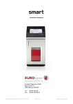
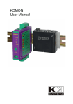
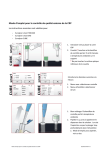
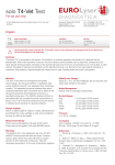
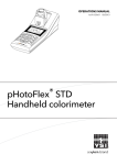
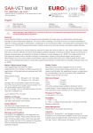
User Manual solo user manual (ED 43204 / revD1 / 06.07.2012) Page 1 of 40 Eurolyser Diagnostica GmbH SYMBOLS AND ABBREVIATIONS The following symbols and abbreviations are used in the product labeling and instructions for the Eurolyser laboratory photometer. Symbol/Abbreviation Explanation Conforms with the European directive 98/79/EC on in vitro diagnostic medical devices In vitro diagnostic medical device Catalogue number / Order number Lot number Serial number The contents are sufficient to perform <n> number of tests Best used by Temperature limitations Relative humidity limitations Manufacturer Date of production Sterile Warnings and precautions, see accompanying documents Operator's action Refer to the user’s manual and follow the instructions Do not dispose with household waste ERS TC ERS Testing Cartridge LED Light Emitting Diode PC Personal Computer solo user manual (ED 43204 / revD1 / 06.07.2012) Page 2 of 40 Eurolyser Diagnostica GmbH ID Identification HIS Hospital Information System LCD Liquid Crystal Display AC Alternating Current DC Direct Current RFID Radio Frequency Identification Table 1 solo user manual (ED 43204 / revD1 / 06.07.2012) Page 3 of 40 Eurolyser Diagnostica GmbH TABLE OF CONTENTS SYMBOLS AND ABBREVIATIONS 2 TABLE OF CONTENTS 4 INTRODUCTION 6 Intended use of the Eurolyser solo laboratory photometer 6 About this user’s manual 6 Inspecting the package contents 6 SYSTEM DESCRIPTION 7 Description of the Eurolyser solo laboratory photometer 7 How to operate the Eurolyser solo laboratory photometer 8 Screensaver 9 Indicator lights 9 How the Eurolyser solo laboratory photometer works 9 Manufacturer’s calibration 9 PICTOGRAMMS / TOUCH BUTTONS 10 The touch screen symbols and their functions 10 Additional symbols and special characters 11 GETTING STARTED 12 The proper placement of the solo laboratory photometer 12 Connecting the power supply 12 How to switch ON the Eurolyser solo laboratory photometer 13 Connecting optional equipment 13 Connecting a barcode scanner 14 Using a barcode scanner 14 The automatic start-up and warm-up processes 15 Configure the Eurolyser solo photometer 16 Setting the normal values and the units, using a T4 test as demonstration 19 How to switch OFF the analyzer 21 TESTING PROCEDURES 22 Overview of the testing and measuring procedures 22 Operating safety precautions 23 Analyzing a patient’s sample 24 Viewing and processing the test results 26 solo user manual (ED 43204 / revD1 / 06.07.2012) Page 4 of 40 Eurolyser Diagnostica GmbH QUALITY CONTROL 27 Choosing quality control (QC) materials 27 Handling the QC control materials 27 Frequency of QC testing 28 CALIBRATION 29 Performing an automatic calibration 29 Performing a manual calibration 30 Example of how to determine the manual calibration factor 31 Performing an instrument calibration 32 CLEANING INSTRUCTIONS 33 Cleaning the Touch Display 33 Cleaning the Door / Cartridge Area 33 Cleaning the Exterior 33 INTERFACE DESCRIPTION 34 Serial Interface 34 USB Interface 34 ERROR INFORMATION AND TROUBLESHOOTING 35 Error messages and possible causes 35 Service information 36 TECHNICAL SPECIFICATIONS 37 Eurolyser solo laboratory photometer 37 Power supply 37 Options 37 DECLARATION OF CONFORMITY 38 SHUT DOWN AND WASTE MANAGEMENT 39 MANUFACTURER DATA 40 solo user manual (ED 43204 / revD1 / 06.07.2012) Page 5 of 40 Eurolyser Diagnostica GmbH INTRODUCTION Intended use of the Eurolyser solo laboratory photometer The Eurolyser solo laboratory photometer is for in vitro diagnostic (clinical chemistry) use only. The solo laboratory photometer is very compact and is designed as a point of care measuring instrument for the ERS (Eurolyser Reagent System). It is easy to use and provides quick, reliable and accurate results. About this user’s manual This user’s manual will guide you through the installation, operation and maintenance of your Eurolyser solo laboratory photometer. The user’s manual also explains how the photometer works, describes the quality assurance system and assists you in troubleshooting any errors or problems. When not used according to the user’s manual the protection of the solo laboratory photometer may be influenced. We recommend that you familiarize yourself with these instructions before operating the Eurolyser solo laboratory photometer. Some of the information in this user’s manual is marked with following symbols: Operator's action Warnings and precautions; see accompanying documents Refer to the user’s manual and follow the instructions Inspecting the package contents When unpacking the solo laboratory photometer, check the contents against the list below and examine the components for signs of shipping damage. The solo package contains the: - Eurolyser solo laboratory photometer Mains adapter Power cable User’s manual If any part of the package is missing or damaged, please report this to your supplier immediately. We recommend that you keep the original packaging, in case the instrument ever needs to be transported. solo user manual (ED 43204 / revD1 / 06.07.2012) Page 6 of 40 Eurolyser Diagnostica GmbH SYSTEM DESCRIPTION Description of the Eurolyser solo laboratory photometer Figure 1 shows the main exterior parts of the solo laboratory photometer (front view). 1. Touch Display The main user interface to operate the instrument and read the results 2. RFID Card Adapter The RFID card is inserted here 3. Door To insert and remove the tests 4. LED The green lightemitting diode (LED) is illuminated when the instrument is connected to the power source Figure 1 Do not open the door manually. Figure 2 describes the main exterior parts of the solo laboratory photometer (rear view). 1 RS232 socket Socket for an (optional) printer or / and barcode scanner 2 USB socket PC connection 3 RS232 socket PC connection 4 Power socket Connects to the power supply Figure 2 solo user manual (ED 43204 / revD1 / 06.07.2012) Page 7 of 40 Eurolyser Diagnostica GmbH How to operate the Eurolyser solo laboratory photometer The solo laboratory photometer is operated solely by means of the touch-screen. All the basic operating steps are displayed as symbols. An overview of these symbols can be found in Table 1 and Table 2. To activate a symbol, touch or tap it with a finger. In order to perform a test, the RFID card enclosed in the test kit must first be inserted into the laboratory photometer. This card contains all the data needed to perform the routine tests. No analysis can be started without the RFID test card! The door opens automatically once a test is initiated by pressing the button. The ERS cartridge is inserted into the slot in the front of the instrument. After entering all the requested data and activating the button on the touch screen, the door closes automatically and the testing procedure begins. After the analysis is completed, the door opens again automatically and the test cartridge can then be removed. The door prevents ambient light, dust, dirt and humidity from entering the laboratory photometer during the testing process and when the instrument is not in use. Do not open the door manually. Use only your fingers to touch the screen. Do not use pens or other hard or sharp objects. 1. Commands / Information 2. Touch Buttons 3. RFID Card 4. Door (closed) Figure 3 solo user manual (ED 43204 / revD1 / 06.07.2012) Page 8 of 40 Eurolyser Diagnostica GmbH Screensaver The screensaver activates after 10 minutes of idle time, dimming the touch screen. Touch the screen to re-activate it. Indicator lights The illuminated green diode (LED) shows that the instrument is connected to the power source. The instrument may be left plugged in indefinitely. How the Eurolyser solo laboratory photometer works The Eurolyser solo laboratory photometer is an open measuring system. That means it is able to use diverse reagents from multiple manufacturers. When tests are to be performed, the solo laboratory photometer is loaded with ERS cartridges, which are filled with reagents from the respective reagent manufacturers. The instrument can process end point tests as well as kinetic tests and – thanks to the latest LED technology – it is maintenance-free. The instrument is equipped with an RFID card-reader module. RFID cards are necessary for performing any testing procedures. They are included in the test kits from the respective test manufacturers and contain all the specific steps for the various tests, the lot data, as well as the calibration data. The instrument performs the tests automatically according to that data. Numerous types of tests can be selected and performed automatically. The sample and the reagent are mixed automatically within the instrument. The photometer unit performs the analysis with either one or two light diode(s). The absorption of light rays is measured during this process, and the measured value is then converted into the test result using mathematical methods. This result is then displayed on the touch screen. Optionally, the results can be exported to an external computer, an HIS, or they can be printed out using an external printer. After the test process, the door opens automatically and the ERS cartridge can then be removed and discarded. After confirming the result, the instrument is ready to perform the next analysis. Manufacturer’s calibration The Eurolyser solo laboratory photometer is manufactured according to the highest quality standards in order to yield safe and accurate testing results. Every instrument is inspected and calibrated during the manufacturing process, using the EU-stipulated reference methods. solo user manual (ED 43204 / revD1 / 06.07.2012) Page 9 of 40 Eurolyser Diagnostica GmbH PICTOGRAMMS / TOUCH BUTTONS The touch screen symbols and their functions Tapping one of these symbols on the touch screen activates the described function. Every symbol that can appear while using the instrument is described here. Symbol Name Function Start the testing entries Opens the menu for additional testing entries Up Selects one entry line or one value higher Down Selects one entry line or one value lower Edit Opens an entry or value so it can be edited Confirm Confirms the input Cancel Cancels the input Delete Deletes the last character entered Option Shows which element is selected Start the analysis Starts the test analysis Printer Starts printing Transmit Starts data transmission Chart Displays the photometer data of the last test Close door Closes the door Results Selects the results menu Forward Go to the next page Backward Go to the previous page Menu backward Go to the previous menu Recycle bin Go to the delete menu Settings Go to the settings menu Sort up Moves/sorts an entry one level up Sort down Moves/sorts an entry one level down Table 2 solo user manual (ED 43204 / revD1 / 06.07.2012) Page 10 of 40 Eurolyser Diagnostica GmbH Additional symbols and special characters Additional symbols or special characters that can appear on the touch screen during operation are described here. These symbols and special characters provide additional information only and cannot be activated by touching. Symbol Name Function Insert cartridge Command to insert the test cartridge Remove cartridge Command to remove the test cartridge Table 3 solo user manual (ED 43204 / revD1 / 06.07.2012) Page 11 of 40 Eurolyser Diagnostica GmbH GETTING STARTED The proper placement of the solo laboratory photometer Place the instrument on a dry, clean, stable and level surface. Make sure that the instrument has at least 10 cm of table surface and clearance on each side and that the instrument can be easily disconnected from the power source. Acclimate the instrument to the ambient room temperature before operating it. The instrument can be damaged by: Condensing humidity and water Heat and large temperature fluctuations Direct sunlight Vibrations (e.g. from centrifuges and dishwashers) Electromagnetic radiation Connecting the power supply - Connect the power cable to the power supply unit. - Insert the plug from the power supply unit into the power socket on the back of the instrument (Figure 4). - Plug the power cable into the wall socket. Always connect to the proper supply voltage. The power supply voltage must comply with the regulations cited in the technical specifications on page 37. The instrument is to be operated only using the power supply unit provided. 1 RS232 socket Socket for an (optional) printer or / and barcode scanner 2 USB socket PC connection 3 RS232 socket PC connection 4 Power socket Connects to the power supply Figure 4 solo user manual (ED 43204 / revD1 / 06.07.2012) Page 12 of 40 Eurolyser Diagnostica GmbH How to switch ON the Eurolyser solo laboratory photometer The instrument is switched on by plugging the power cable into the socket. This launches the instrument’s automatic start-up and warm-up processes. Please wait for these to be completed (approximately 15 minutes). Do not open the door manually. Connecting optional equipment The following optional devices – which are not included in the standard delivery package – can be connected to the instrument: An external printer – for optional test result printouts An external barcode scanner A PC – for the transfer of test data into an HIS or laboratory software We recommend the DPU-414 from SEIKO as an optional printer, as described in the “Technical specifications” section on page 37. Connect optional equipment only when the instrument is switched off. Please note that attaching optional equipment (e.g. a printer) can increase the amount of leakage current. All optional equipment must be connected before such leakage current can be measured. If the instrument is not used according to the instruction manual, then the provided levels of safety will be lowered. solo user manual (ED 43204 / revD1 / 06.07.2012) Page 13 of 40 Eurolyser Diagnostica GmbH Connecting a barcode scanner To install the Datalogic Touch 65 barcode reader (Order number: SZ0400) please connect the RS232 cable to the outer RS232 socket at the analyzer (see illustration). Always connect the power supply to the barcode scanner correctly before using it. If a printer should be installed simultaneously an adapter (barcode-printer-interface-cable, order number: SZ0405) has to be interconnected. The barcode reader can handle barcodes up to 16 digits. 1 RS232 socket Socket for an (optional) printer or / and barcode scanner 2 USB socket PC connection 3 RS232 socket PC connection 4 Power socket Connects to the power supply Figur 5 Using a barcode scanner 1. Start-up menu First start a test by touching . 1 2. Operator menu* 1 3. Operator insert menu* When you reached the operator After you reached the operator menu you will be able to scan the insert menu you will also be able operator with the barcode to scan the operator with the scanner. The operator will be barcode scanner. created automatically. 1 * Note: This menu only appears once the operator input is enabled (p. 21). solo user manual (ED 43204 / revD1 / 06.07.2012) Page 14 of 40 Eurolyser Diagnostica GmbH 4. Insert menu 5. ID insert menu When you reached the insert It is also possible to use the menu you will be able to scan the barcode scanner while being ID with the barcode scanner. inside the ID insert menu. Data will be put automatically into the ID field. Note: One can either use the barcode scanner in the operator menu and insert menu or within the operator insert menu and ID insert menu. The automatic start-up and warm-up processes 1. Warm-up menu 2. Interrupting the warm-up process (optional) 3. Start-up menu The automatic start-up procedure starts as soon as the instrument is connected to the power supply. The instrument is warmed up to its proper working temperature in approx. 15 minutes. If you want to interrupt the warm-up process, just touch Warmup in process. A submenu appears; press to interrupt. However, if you don’t want to interrupt the process, press . As soon as the entire progress indicator gets full and the initialization of the optical unit is completed (in a few more seconds), the start-up menu appears. The instrument is now operational. solo user manual (ED 43204 / revD1 / 06.07.2012) Page 15 of 40 Eurolyser Diagnostica GmbH Configure the Eurolyser solo photometer You can configure your Eurolyser solo laboratory photometer according to your needs before you begin using it. To go to the configuration menu, follow these steps: 1. Start-up menu Touch 2. Settings menu to go to the Settings menu. 4. Language menu 3. Configuration menu Touch Settings, to go to the Touch the setting you want to Settings/Configuration menu. configure. 5. Interface menu 6. Interface printer menu Touch the preferred language Select the interface you want to Select Printout for further and confirm it with configure. Choose Printer to configuration regarding printouts configure transmission to a of test result(s). Select Options to connected printer. Choose Host configure whether Operator, Lot to configure transmission to a No or Serial No should be host (e.g. a PC). included in the printout or not. . solo user manual (ED 43204 / revD1 / 06.07.2012) Page 16 of 40 Eurolyser Diagnostica GmbH 7. Interface printout menu 8. Interface printer option menu 9. Interface host menu If a printer is connected: Select Operator, Lot No or Serial Select Transfer for further Disable = printouts will never be No to define if they should be configuration regarding transfer of provided. included in the printout or not by test result(s). Select Option to Automatic = the results will be choosing Disable or Enable. configure whether Operator, Lot printed out after every No or Serial No should be measurement. included in the transfer and which On request = printouts will only be baud rate is used when provided on demand. transferring to a host. The service password to change the settings is required. 10. Interface host transfer menu 11. Password menu 12. Interface host option menu If a host (e.g. a PC) is connected: The service password is required Select Operator, Lot No or Serial Disable = data will never be to change interface host options. No to define if they should be transmitted. included in the transfer to a host Automatic = the results will be or not by choosing Disable or transmitted to the host after every Enable. Select Baud to change measurement. the baud rate when transferring to On request = data will only be a host. transmitted upon request. solo user manual (ED 43204 / revD1 / 06.07.2012) Page 17 of 40 Eurolyser Diagnostica GmbH 13. Interface host baudrate menu 14. Date / time menu Select the desired baud rate for Touch to go to the Date transferring to a host. detail and Time detail menus. 15. Date detail menu Touch to change the selected entry. Use or to navigate on the screen. 16. Day date menu 17. Date format menu 18. Time detail menu Touch the desired digits and Select your preferred date format. Touch confirm the selected date with DD = Day input or Time format menus. To MM = Month navigate within the screen, use . YYYY = Year 19. Time input menu Select either the 12-hour time and confirm your selection with format (1 – 12 AM/PM) or the 24- solo user manual (ED 43204 / revD1 / 06.07.2012) . 20. Time format menu Touch the digits to enter the time . and to go to the Time hour time format (0 – 23). Page 18 of 40 Eurolyser Diagnostica GmbH Setting the normal values and the units, using a T4 test as demonstration 1 2. Test selection menu* 1. Configuration menu Touch Norm Values to change Confirm the selection of T4 with the norm values. . 4. Limits detail menu Enter the desired value by pressing the pressing the number buttons. 1 Confirm the selection T4 with . 6. Configuration menu Edit the according limits by 7. Test selection menu* Select the specie you want to edit with 5. Limits change menu Button. 3. Limits menu Touch Units to change the units. 8. Units selection menu . Touch the selected unit and confirm it with . This description is only an example, as the configuration of the Eurolyser laboratory photometer models varies, depending on the tests used. 1 * Note: If only one test is used on the solo, the test selection menu will be skipped. solo user manual (ED 43204 / revD1 / 06.07.2012) Page 19 of 40 Eurolyser Diagnostica GmbH 9. Configuration menu 10. Input menu 11. Default specie menu Touch Input to reach the input Select which values to change Select which additional specie is menu. from the Input menu. to be added with Additional. Choose Order to change the order of the specie. 2 12. Additional specie menu* 13. Specie entry menu 14. Specie order menu Select which specie entry should Enter the species’ name and Select which entry should be be edited and confirm with confirm the entry with edited by browsing with the . . To delete an incorrect entry, use cursor buttons. Change the order . up or down with the and buttons. 3 15. Default sample type menu* 16. Specie menu 17. HCT default input menu Select which type of sample Select which specie’s HCT should Enter the hematocrit value and should be marked by default. Last be changed confirm it by pressing . . used means the sample type last used will be selected. 2 * Note: Additionally to the pre-defined species one can add up to 10 more free-defined species. 3 * Note: If more than one test is used on the solo you will have to select the test you want to edit the default settings. solo user manual (ED 43204 / revD1 / 06.07.2012) Page 20 of 40 Eurolyser Diagnostica GmbH 18. Operator menu 19. Default operator menu Select Operator to change the Select Disable if you want to default settings for operator input disable selecting an operator (see 14). Touch Delete All to when performing a test. Select delete all currently saved Enable to use operators when operators. Touch Delete to delete performing a test. Accept new a single operator. settings with . How to switch OFF the analyzer Completely turning off the instrument can only be accomplished by disconnecting it from the power supply. It is not necessary to switch the instrument off every day. When the instrument is in start screen mode, the “power safe” function dims the screen after it has been idle for 10 minutes. Touching the screen will re-illuminate it to its customary level of brightness. solo user manual (ED 43204 / revD1 / 06.07.2012) Page 21 of 40 Eurolyser Diagnostica GmbH TESTING PROCEDURES Overview of the testing and measuring procedures Allow the ERS test cartridge to reach room temperature before use. If the solo laboratory photometer has been disconnected from the power supply, plug it in soon enough for it to be at the proper operating temperature when it is needed. How to run a control test, if necessary: - Insert the RFID card from the test kit into the slot on the front of the instrument. - Prepare the control serum according to the instructions on the control package insert. - Enter the lot number instead of the patient data. - Prepare the test just like a patient sample and start the analysis. - The result is displayed. - Record the result according to your laboratory’s quality guidelines. - The result will be saved in the instrument’s memory – just like a patient’s results. - Export the result to an (optional) external computer, or print the result with an (optional) external printer. - Verify that the result lies within the mandatory limits for the control material (according to the control material’s package insert). To analyze a patient sample: - Insert the RFID card from the test kit into the instrument. - Prepare a test cartridge and a patient sample according to the instructions on the test kit insert. - Enter the required patient data. - Insert the test cartridge into the analyzer and start the analysis. - The result will be displayed. - The result will be saved in the instrument’s memory. - Export the result to an (optional) external computer, or print the result with an (optional) external printer. Be sure to follow the detailed instructions for the analysis processes that are provided in the following sections and to comply with the information provided on the package insert enclosed with each test kit. solo user manual (ED 43204 / revD1 / 06.07.2012) Page 22 of 40 Eurolyser Diagnostica GmbH Operating safety precautions When operating the laboratory photometer: Use only your fingertip to operate the touch screen. Do not use pens or any other objects that may scratch or damage the screen. • If an error message appears on the screen during an analysis, please consult the “Troubleshooting” section on page 35. • The door protects the analysis system from dust, dirt and humidity. Empty the door’s cartridge chamber after every analysis and keep it closed when the instrument is not in use. • The door opens and closes automatically. Do not try to open or close the door manually. When handling a test cartridge: • Do not use test cartridges after their expiration date, or when the test cartridges have not been stored in accordance with the regulations. • Do not use the test cartridge if the packaging is damaged or if fluids have leaked. • The test cartridge must reach room temperature (18-28°C; 64,4- 82.4 °F) before use. • Use gloves when handling and disposing of the test cartridges, patient samples and sample collection equipment, because they pose a potential biohazard. • Use the test cartridge only once. • Only use the test cartridges that are specified and approved by the manufacturer. See the package insert that comes with all test cartridges suitable for use with the Eurolyser solo laboratory photometer and follow all instructions regarding: • the proper temperature a cartridge must have before a test is performed. • the exact amount of the sample volume. • the regulations for the proper storage of the test cartridges. solo user manual (ED 43204 / revD1 / 06.07.2012) Page 23 of 40 Eurolyser Diagnostica GmbH Analyzing a patient’s sample 1. Startup menu 1 3.Operator input menu* 2. Main menu Take the provided RFID card out The instrument automatically The first time when performing a of the test package and insert it reads the card, displays the type test you will be prompted to input into the instrument. of test, number of tests, the expiry an operator. Choose New to date and lot number. Touch define an operator. All saved , the door opens operators will be shown in this automatically. menu whenever you perform another test. 4. Input menu Touch 5. ABC menu The ABC menu 6. Numeral menu Enter the name and confirm the Enter the patient ID and confirm it appears. To navigate within the entry with with input menu, use incorrect entry, use and . To delete an . . To delete an incorrect entry, use . . 7. Input menu – Specie / Control 8. Sample type menu 9. Hematocrit menu (not for all tests) (not for all tests/sampletypes) Touch Control or the desired Touch Pipette20µ or Pipette5µ and Enter the hematocrit value and specie and confirm the selection confirm the selection with confirm it with with . . . 1 * Note: This menu only appears once the operator input is enabled (p. 21). solo user manual (ED 43204 / revD1 / 06.07.2012) Page 24 of 40 Eurolyser Diagnostica GmbH 10. Start analysis menu Fully insert the test cartridge into the analyzer. Touch the door closes and the test is performed automatically. The instrument displays the following information during the automatic testing process: (Varies by test type) 11. Mixing 12. Incubating 13. Measuring Be sure to handle the test cartridge according the instructions on the package insert. Be sure the test cartridge is properly sealed before you insert it into the analyzer. Be sure the test cartridge is fully inserted into the proper opening in the analyzer. Use ONLY manufacturer-approved test cartridges, otherwise serious damage to the solo photometer or inaccurate test results may occur. Do not attempt to open or close the door manually. solo user manual (ED 43204 / revD1 / 06.07.2012) Page 25 of 40 Eurolyser Diagnostica GmbH Viewing and processing the test results The solo laboratory photometer can store up to 250 patient and control results in its memory. When this capacity is exceeded, the oldest results are overwritten in chronological order. 1. Single result menu 2. Remove cartridge menu The result is shown. Touch print it. Touch to to export it to an HIS or PC, or touch to display the photometric data. Remove the cartridge and touch 3. Overall result menu The instrument automatically To scroll through the results, opens the door. Remove the test touch cartridge and discard it. Touch print the result(s); touch to close the door. The main menu appears. to close the menu and end the test. If you do not remove the or Touch to to send the result(s) electronically. Touch to delete the result(s). Touch to return to the main menu. cartridge before accepting the result the Remove cartridge menu will appear. Whenever the transmission of the operator id, lot number and serial number is activated in the appropriate settings menu (pp. 16 – 17) they will be transfered to the printer or a host system automatically and can be viewed on printouts or the computer / host system. solo user manual (ED 43204 / revD1 / 06.07.2012) Page 26 of 40 Eurolyser Diagnostica GmbH QUALITY CONTROL A quality control program should be performed on a regular basis to verify the Eurolyser solo laboratory photometer is working properly and providing reliable results. Data integrity can only be assured when controls and GCLP practices are used routinely. The frequency of performing QC differs from laboratory to laboratory; please comply with your national quality control regulations. Choosing quality control (QC) materials The authorized manufacturers of the solo test cartridges also supply control materials. These control kits contain control materials, which allow you to assess the measuring accuracy of the instrument. Ensure the measuring methods are compatible with the Eurolyser solo laboratory photometer before using QC kits from other suppliers. The measuring methods are listed on the test cartridge’s package insert. Handling the QC control materials Consult the package insert that comes with each control kit for detailed instructions on the storage and handling of the control materials. Follow the instructions in the “Analyzing a patient’s sample” sections (pp. 24-25) on how to properly perform a control test. The measured values must be within the range of target values specified on the control vial label or in the control package insert. If the control results fall within the specified range, the testing of patient samples may begin. If one or more controls tested are outside the specified control range: - Verify that the control materials have been stored according to the directions and that the expiration date has not passed Verify that the handling and testing procedures were performed according to the directions on the package insert Repeat the control test, using a new control from the same lot If one or more control results are still outside the specified range: - Perform a test using a control from a new lot. If the above instructions have been followed, but the control results are still not within the permitted range, contact your local Eurolyser solo laboratory photometer supplier for assistance before proceeding with tests on any patient samples. solo user manual (ED 43204 / revD1 / 06.07.2012) Page 27 of 40 Eurolyser Diagnostica GmbH Frequency of QC testing Control testing is recommended when: a new shipment of test kits is about to be used. a new lot is about to be used. if it’s possible that the test cartridges have not been properly stored. if an unexpected patient result is obtained. when new personnel is being trained to use the equipment . if local regulations require more frequent control testing than described above, then the number of control tests performed must comply with these regulations. solo user manual (ED 43204 / revD1 / 06.07.2012) Page 28 of 40 Eurolyser Diagnostica GmbH CALIBRATION All test kits that are made for the Eurolyser solo photometer are calibrated by the manufacturer during production. A calibration of the photometer therefore is not necessary. Nevertheless the instrument offers the opportunity to do a specific calibration if the operator wishes to. The instrument is set to perform either an automatic calibration using a calibration kit or a manual calibration by entering a factor. You’ll need the proper calibration kit to perform an automatic calibration. The kits differ depending on the type of test being performed. Please follow the instructions in the calibration kit’s package insert. Performing an automatic calibration 1. Start-up menu Touch to go to the Settings menu. 4. Calibration options menu 2. Settings menu 3. Calibration options menu Touch Calibration to go to the Select Test kit to go to the Calibration options menu. Calibration options menu. 5. Calibration card menu 6. Calibration data menu To perform an automatic The instrument asks you to insert The instrument reads the calibration, touch Auto. the calibration RFID card calibration data from the card. supplied with the calibration kit. Confirm it with solo user manual (ED 43204 / revD1 / 06.07.2012) Page 29 of 40 . Eurolyser Diagnostica GmbH 7. Insert test card menu 8. Confirmation menu 9. Start analysis menu Insert the test RFID card Confirm the data of the test to be Fill the test cartridge with the supplied with the test kit. The calibrated with calibration material according to . confirmation menu appears. the instructions on the calibration kit’s package insert. Insert the cartridge and touch . The calibration will be performed automatically. Note: the calibration applies only to the respective test kit being used! If the above instructions have been followed, but the control results are still not within the permitted range, contact your local Eurolyser solo laboratory photometer supplier for assistance before performing the next test on a patient’s sample. Performing a manual calibration 1. Start-up menu Touch to go to the Settings menu. solo user manual (ED 43204 / revD1 / 06.07.2012) 2. Settings menu 3. Calibration options menu Touch Calibration to go to the Select Test kit to go to the Calibration options menu. Calibration options menu. Page 30 of 40 Eurolyser Diagnostica GmbH 4. Calibration options menu 5. Password menu 6. Manual calibration menu To perform a manual calibration, Enter the password. The default The data of the test kit to be touch Manual. setting is 3010. Confirm it with calibrated is displayed. Confirm it . with . 7. Detail entry menu Change the factor according to the difference from the target value of a control serum. Confirm it with . To delete an incorrect entry, use . Example of how to determine the manual calibration factor The calibration factor can be determined empirically by analysing a control serum: The target value of the control serum is e.g.: 3.6mg/l – 6.4mg/l The measured value of the control serum is e.g.: 8.00 mg/l In this case, the value is too high, the calibration factor must be decreased (the default value is 100). Decrease the calibration factor by 5 units. The default value is 100, set the new factor at 95 and repeat the measurement of the control serum. If the result is still outside the control serum’s specified range decrease the factor by another 5 units and repeat the procedure. solo user manual (ED 43204 / revD1 / 06.07.2012) Page 31 of 40 Eurolyser Diagnostica GmbH Performing an instrument calibration 1. Start-up menu Touch to go to the Settings menu. 4. Password menu Enter the password. The default 2. Settings menu 3. Calibration options menu Touch Calibration to go to the Select Instrument to perform an Calibration options menu. instrument calibration. 1 5. Test selection menu* Confirm the selection T4 with 6. Factor and Offset input menu . setting is 3010. Confirm it with Enter the factor and the offset accordingly. Confirm them with . . 1 * Note: If only one test is used on the solo, the test selection menu will be skipped. solo user manual (ED 43204 / revD1 / 06.07.2012) Page 32 of 40 Eurolyser Diagnostica GmbH CLEANING INSTRUCTIONS Cleaning the Touch Display Clean the touch display with a clean, lint-free cloth moistened with water. Do not use any liquid except of water when cleaning the touch display! To avoid damage do not spill liquid onto the display! Cleaning the Door / Cartridge Area Clean the door with a clean, lint-free cloth moistened with isopropyl alcohol. Wipe down the surface. The cartridge area may be cleaned with a cotton swab moistened with isopropyl alcohol. Cleaning the Exterior Do not clean the touch panel with isopropyl alcohol! Refer to “Cleaning the Touch Display” on how to clean the touch panel. The exterior may be cleaned with a clean, lint-free cloth moistened with isopropyl alcohol. Wipe down the exposed surfaces. solo user manual (ED 43204 / revD1 / 06.07.2012) Page 33 of 40 Eurolyser Diagnostica GmbH INTERFACE DESCRIPTION Serial Interface Interface signals Pin 1 2 3 4 5 6 7 8 9 Interface parameters Parameter Signal Baud rate TxD RxD Data bits Parity Stop bits GND Value 9600 Default 115200 8 None 1 Data format Data is transmitted in blocks of data sets. One data set contains the data from one analysis. Data sets consist of data fields. A data field consists of an identifier (7 characters) and its respective value or text. Data fields are concluded with one carriage return and line feed. Data sets are concluded with three carriage returns and line feeds. Data Fields Identifier Format Example Remarks Name: ID: Holder: Specie: Sample: HCT: Testname: Calculatedname: Range: Time: Date: Operat: Lot No: Ser No: Text Text Text Text Text Value Value and unit Value and unit Value – Value hh:mm dd-mm-yyyy Text Value Value Name: Snoopy ID: 1234 Holder:John Doe Specie:Dog Sample:Blood HCT: 40 T4: 2.48 µg/dl eAG: 100 mg/dl Range: 0.00 – 1.00 Time: 14:44 Date: 08-02-2007 Operat:Max Muster Lot No:4111 Ser No:Ba00001 Optional Optional Optional Optional Optional Optional Optional USB Interface The USB interface emulates the serial interface. solo user manual (ED 43204 / revD1 / 06.07.2012) Page 34 of 40 Eurolyser Diagnostica GmbH ERROR INFORMATION AND TROUBLESHOOTING Error messages and possible causes Error message Cause Correction Invalid card A wrong, defective or expired RFID card A defective RFID module No test results are stored The calibration values are outside the prescribed range. An error occurred during calibration. The test cartridge has passed its expiration date. The calibration interval has been exceeded The test cartridge is blocking the door because the cartridge has not been inserted completely or the cuvette has not been capped firmly enough. The wrong ERS cap is being used or the ERS cap is missing or the cartridge is missing or an already used cartridge is inserted The test cartridge blocks the bolt because the wrong ERS cap is being used. The photometric measurement value is outside the measuring range (e.g. if a cold cartridge has been used) The photometric measurement value is outside the measuring range (without the cartridge) The temperature is outside the range The wrong sample type has possibly been selected The reaction of kinetic test is not linear (e.g. if a cold cartridge has been used, if wrong sampletype was set, if wrong samplevolume was used or if a cartridge with integrated capillary was not used correctly) Instrument fails to perform test due to possible hardware error Use a new test kit No results Calibration failed Tests expired Calibration required Door blocked Wrong cap Missing cap Missing cartridge Bolt blocked Measurement overflow Blank Error Temperature error Wrong sample type? Linearity error Mix error contact your local dealer Coagulation error Sample volume error Cartridge temperature error solo user manual (ED 43204 / revD1 / 06.07.2012) Contact your dealer Perform the test Repeat the calibration with a new test kit or a new calibrator. If the problem reocurrs, contact your dealer. Use a cartridge from a new test kit that has not expired. Perform a new calibration Reposition the test cartridge or tighten the cap on the cuvette. Use the correct ERS cartridge and cap Use the correct ERS cartridge and cap Repeat the test using a new cartridge Repeat the test after restarting the instrument Repeat the test after restarting the instrument Select the correct sample type Repeat the test using a new sample and a new cartridge Please contact your local dealer. Coagulation can not be measured Repeat the test using a new cartridge The provided sample volume is not Repeat the test using a new correct (e.g. pipetting error) cartridge with correct sample volume The cartridges’ temperature is too Repeat the test and refer to the low for a proper test. package inserts for proper cartridge use. Page 35 of 40 Eurolyser Diagnostica GmbH Service information If the problem persists after the corrective actions are taken, contact your local solo laboratory photometer dealer for technical assistance. Before asking for assistance, please have the following information ready: the serial number of your solo laboratory photometer the test type the test lot number the control lot number the control results obtained so far a description of the problem, including any of the solo’s error messages solo user manual (ED 43204 / revD1 / 06.07.2012) Page 36 of 40 Eurolyser Diagnostica GmbH TECHNICAL SPECIFICATIONS Eurolyser solo laboratory photometer Photometer resolution 0.0001 ABS Reproducibility <1.5% CV at 1 OD Linearity 0.1000 – 3.0000 OD better than +/- 1.5% and +/- 0.01 OD Temperature control Electrical temperature control of the photometer unit to 37°C +- 2°C Display Standard color LCD display with back light and integrated touch panel Buffer battery BR2032 Fuse 2.5 amperes, self-healing Dimensions 260 x 145 x 140 cm (H x B x T) Weight 3.5 kg (unpackaged) Communications interface RS232, USB Tolerance conditions: Work space: 18 - 28°C; relative humidity: 10 – 85% Transport/Storage: 0 - 50°C; relative humidity: 5 – 85% Work surface: A dry, clean, level surface. Avoid direct sunlight. Power usage: 12V DC, 2A Power supply Manufacturer Type Mains adapter Input Output Globtek GTM21097-5012 A separate AC to DC mains adapter with double insulation 90-264V AC, 47-63 Hz 12V DC, 4.17A Options Thermo printer Seiko DPU-414 Interface Serial Mains adapter 100-240 VAC Barcode reader (scanner) Datalogic Touch65 Reading area 63mm Max. resolution 0.10mm (4mils) Mains adapter 100-240 VAC solo user manual (ED 43204 / revD1 / 06.07.2012) Page 37 of 40 Eurolyser Diagnostica GmbH DECLARATION OF CONFORMITY Declaration of conformity with IVD directives The Eurolyser solo laboratory photometer is in compliance with all provisions in the directive 98/79/EC on In Vitro Diagnostic medical technology products and is CE-marked as conforming to standards. Safety standards The Eurolyser solo laboratory photometer has been tested and conforms to the safety standards IEC/EN 61010-1, IEC/EN 61010-2-081 and IEC/EN 61010-2-101, as well as to the EMC standard IEC/EN 61326. solo user manual (ED 43204 / revD1 / 06.07.2012) Page 38 of 40 Eurolyser Diagnostica GmbH SHUT DOWN AND WASTE MANAGEMENT For proper waste management according to the directive 2002/96/EG please contact your local dealer. Used cartridges need to be disposed with the laboratory waste and according to its’ correct regulations. Before shutting down the solo laboratory photometer for the purpose of a repair or dispense it is needed to make sure there is no cartridge left within the solo laboratory photometer. For the purpose of delivering the solo laboratory photometer it is also required to protect the photometer with its’ original delivered packaging and packaging inserts. solo user manual (ED 43204 / revD1 / 06.07.2012) Page 39 of 40 Eurolyser Diagnostica GmbH MANUFACTURER DATA EUROLYSER DIAGNOSTICA GmbH Bayernstrasse 11a 5020 Salzburg AUSTRIA Tel: +43 662 432100 Fax: +43 662 432100-50 www.eurolyser.com Contact: Gerhard Bonecker, MBA solo user manual (ED 43204 / revD1 / 06.07.2012) Page 40 of 40 Eurolyser Diagnostica GmbH