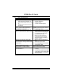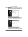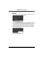
1
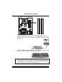
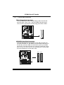
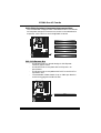
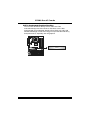
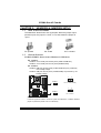
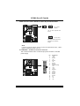
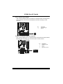
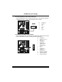
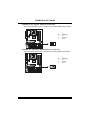
PT880 Pro-A7 Combo
FCC Information and Copyright
This equipment has been tes ted and found to comply with the limits of a Class
B digital devic e, purs uant to Part 15 of the FCC Rules . T hese limits are designed
to provide reasonable protec tion against harmful interference in a residential
installation. T his equipment generates , uses and can radiate radio frequency
energy and, if not ins talled and used in accordance with the instructions , may
cause harmful interference to radio communications . There is no guarantee
that interference will not occur in a particular ins tallation.
The vendor makes no representations or warranties with respec t to the
contents here and s pecially disclaims any implied warranties of merchantability
or fitness for any purpose. Further the vendor reserves the right to revise this
publication and to make c hanges to the c ontents here without obligation to
notify any party beforehand.
D uplication of this publication, in part or in whole, is not allowed without first
obtaining the vendor’s approval in writing.
The content of this user’s manual is subject to be c hanged without notice and
we will not be res ponsible for any mis takes found in this user’s manual. All the
brand and produc t names are trademarks of their respec tive companies .
i
Table of Contents
Chapter 1: Introduction .......................................................................1
1.1
1.2
1.3
Chapter 2:
2.1
2.2
2.3
2.4
Chapter 3:
3.1
3.2
Chapter 4:
4.1
4.2
4.3
Motherboard Features .......................................................... 1
Package List......................................................................... 4
Layout and Components....................................................... 5
Hardware Installation...................................................6
Installing Central Processing Unit (CPU)................................ 6
FAN Headers....................................................................... 8
Installing System Memory .................................................... 9
Connectors and Slots ...........................................................10
Headers & Jumpers Setup....................................... 13
How to Setup Jumpers.........................................................13
Detail Settings.....................................................................13
Useful Help .................................................................. 20
Award BIOS Beep Code.......................................................20
Extra Information ................................................................20
Troubleshooting ..................................................................22
Chapter 5: WarpSpeeder™.............................................................. 23
5.1
5.2
5.3
5.4
Introduction ........................................................................23
System Requirement............................................................23
Installation ..........................................................................24
[WarpSpeeder™] includes 1 tray icon and 5 panels................25
Appendix:
........................................................................................ 32
Certified PCI-Express VGA Card List.....................................................32
ii
PT880 Pro-A7 Combo
CHAPTER 1: INTRODUCTION
1.1
MOTHERBOARD FEATURES
CPU
Supports LGA 775.
Supports Intel Pentium 4 processor up to 3.8GHz.
Supports Intel Pentium D processor.
Supports Intel Celeron D processor.
Front side bus at the following frequency ranges:
533MHz (133MHz Core Clock)
800MHz (200MHz Core Clock)
Supports Hyper-Threading Technology.
WARNING!
Warranty will be void if the pin protection cap is not i n plac e to pr otect the soc ket pin
when s ending this mai nboard for ser vice.
Chipset
North Bridge: VIA PT880 Pro.
South Bridge: VIA VT8237R PLUS.
Dimension
ATX Form Factor: 29.3cm (L) x 23.5cm (W)
O perating System Supporting
Supports Windows 98 / Me / 2000 / XP.
Slot
Four 32-bit PCI bus master slots.
One AGP 3.0 (8X) compatible slot.
One PCI-Extreme (PE1) slot. (See p.11 for detail information)
Onboard AC’97 Sound CODEC
Chip: REALTEK ALC655.
Support 6 channels.
Supports SPDIF-out and SPDIF-in (optional) functions.
Compliant with AC’97 Version 2.3 specification.
1
PT880 Pro-A7 Combo
Supe r I/O
Chip: ITE 8705AF.
Provides the most commonly used legacy super I/O
functionality.
Environment Control initiatives:
H/W Monitor.
Fan Speed Controller.
ITE “Smart Guardian” function.
System Memory
Supports Dual Channel DDR/DDR2.
Supports DDR2 400/533 memory and up to 2GB physical
memory. (DDR2A1/DDR2B1)
Supports DDR 200/266/333/400 memory and up to 2GB
physical memory. (DDR1A2/DDR1B2)
DDR and DDR2 memory capacity cannot be added together.
Supports non-ECC memory only.
Registered DIMMs are not supported.
DIMM Socket
Location
DDR2A1
DDR2B1
DDR/DDR2 Module
Total Memory Size
256MB/512MB/1GB *1
256MB/512MB/1GB *1
Max is 2GB.
DDR1A2
DDR1B2
256MB/512MB/1GB *1
256MB/512MB/1GB *1
Max is 2GB.
10/100 LAN PHY
PHY: RTL8201CL.
Supports 10 Mb/s and 100 Mb/s auto-negotiation.
Half/Full duplex capability.
Supports ACPI, PCI power management.
Onboard Serial ATA
Integrated in VT8237R PLUS.
Supports RAID 0 and RAID 1 functions.
Supports 2 serial ATA (SATA) ports.
Data transfer rates up to 150 MB/s.
Compliant with SATA Version 1.0 specification.
2
PT880 Pro-A7 Combo
Onboard IDE
Two IDE connectors support 4 hard disk drives.
Supports PIO mode 0~4.
Supports Ultra DMA 33/66/100/133 Bus Master Mode.
Inte rnal On-board I/O Conne ctors and Heade rs
1 front panel header supports front panel facilities.
1 CD-in connector supports 1 CD-ROM audio-in device.
1 front audio header supports front panel audio-out function.
1 S/PDIF-Out connector supports digital audio-out function.
1 S/PDIF-In connector supports digital audio-in function
(optional).
1 chassi s open header supports PC case-opened warning
function.
1 FDD connector supports 2 Floppy drives with 360K, 720K,
1.2M, 1.44M and 2.88Mbytes.
2 IDE connectors support 4 hard disk devices.
2 Serial ATA connectors support 2 SATA devices.
2 USB headers support 4 USB 2.0 ports at front panel.
Back Panel I/O Conne ctors
4 USB 2.0 ports.
1 COM port. (COM2 is optional)
1 Printer port.
1 RJ-45 LAN jack.
1 PS/2 Mouse port.
1 PS/2 Keyboard port.
1 Vertical audio port including 1 line-in connector, 1 line out
connector, and 1 MIC in connector.
LAN
PS/2
Mouse
Pri nter Port
Line I n/
Surround
Line O ut
COM1
PS/2
Keyboard
M ic In 1/
B ass/Center
COM2
(optional)
USB x2
3
USB x2
PT880 Pro-A7 Combo
1.2
PACKAGE LIST
FDD cable x 1
HDD cable x 1
User’s Manual x 1
Fully Setup Driver CD x 1
Rear I/O panel for ATX case x 1
USB 2.0 cable x 1 (optional)
Serial ATA cable x 1 (optional)
S/PDIF out cable x 1 (optional)
4
PT880 Pro-A7 Combo
1.3
LAYOUT AND COMPONENTS
JK BMS1
JA UXPWR 1
LGA775
JK BV 1
J COM1
CPU 1
J PRNT 1
JCOM2
DD R1B2
DD R2B1
DD R2A1
DD R1A2
J CFAN 1
(opt o
i nal)
JUSB1
JUS BV2
PT880 Pro
JUS BLAN1
JATXPWR1
J AUDI O1
J AUDI O2
LAN
C OD E C
JSFAN1
JWOL1
(opt ional )
JCMOS1
AGP1
PE1
BAT1
JS PD IF_IN1
(optional)
PCI1
J SATA2
VT823 7R
PLUS
JCD IN1
JDJ 1(opt o
i nal)
J SPD IF_OU T1
PCI2
J SATA1
Super I/O
PCI3
JPANEL1
BIOS
PCI4
st
Note: ■ represents the 1 pin.
5
FD D1
J USB4
IDE1
JU SB3
ID E2
JUSBV 3
JC I1
PT880 Pro-A7 Combo
CHAPTER 2: HARDWARE INSTALLATION
2.1
INSTALLING CENTRAL PROCESSING UNIT (CPU)
Special Notice:
Remove Pin Cap before installation, and make
good preservation for future use. When the CPU
is removed, cover the Pin Cap on the empty
socket to ensure pin legs won’t be damaged.
Pin Cap
Step 1: Pull the socket locking lever out from the socket and then raise
the lever up to a 90-degree angle.
6
PT880 Pro-A7 Combo
Step 2: Look for the triangular cut edge on socket, and the golden dot on
CPU should point forwards this triangular cut edge. The CPU will
fit only in the correct orientation.
Step 2-1:
Step 2-2:
Step 3: Hold the CPU down firmly, and then lower the lever to locked
position to complete the installation.
Step 4: Put the CPU Fan and heatsink assembly on the CPU and buckle it
on the retention frame. Connect the CPU FAN power cable into
the JCFAN1. This completes the installation.
7
PT880 Pro-A7 Combo
2.2
FAN HEADERS
These fan headers support cooling-fans built in the computer. The fan
cable and connector may be different according to the fan manufacturer.
Connect the fan cable to the connector while matching the black wire to
pin#1.
JCFAN1: Powe r Source He ade r for CPU Fan
1
4
Pin
1
2
3
4
Assignment
Ground
Power
FAN RPM rate
sense
Smart Fan
Control
JSFAN1: Powe r Source Heade r for System Fan
Pin
1
2
3
3
Assignment
Ground
+12V
FAN RPM rate
sense
1
Note:
The JCFAN1 res erves cooling fan with Smart Fan Control utility. It supports 4-pin head
connector. When c onnecti ng with wires onto c onnectors, pl ease note that the r ed wire is
the positi ve and s hould be c onnected to pin#2, and the blac k wire is Ground and s hould
be c onnected to GND.
8
PT880 Pro-A7 Combo
DDR 1B2
DDR 2B1
DDR 1A2
INSTALLING SYSTEM MEMORY
DDR 2A1
2.3
1. Unlock a DIMM slot by pressing the retaining clips outward. Align a
DIMM on the slot such that the notch on the DIMM matches the break
on the Slot.
2. Insert the DIMM vertically and firmly into the slot until the retaining chip
snap back in place and the DIMM is properly seated.
Notice:
1.
2.
3.
For DDR2 modules , pl ease insert DIMMs into DDR2 DIMM slots (DDR2A1/DDR2B1).
For DDR1 modules , pl ease insert DIMMs into DDR1 DIMM slots (DDR1A2/DDR1B2).
DDR1 and DDR2 memory capacity c annot be added together.
9
PT880 Pro-A7 Combo
2.4
CONNECTORS AND SLOTS
FDD1: Floppy Disk Connector
The motherboard provides a standard floppy disk connector that
supports 360K, 720K, 1.2M, 1.44M and 2.88M floppy disk types.
This connector supports the provided floppy drive ribbon cables.
34
33
2
1
IDE1/IDE2: Hard Disk Connectors
The motherboard has a 32-bit Enhanced PCI IDE Controller that
provides PIO Mode 0~4, Bus Master, and Ultra DMA 33/66/100/133
functionality. It has two HDD connectors IDE1 (primary) and IDE2
(secondary). The IDE connectors can connect a master and a slave
drive, so you can connect up to four hard disk drives. The first hard
drive should always be connected to IDE1.
IDE2
40
2
10
IDE1
39
1
PT880 Pro-A7 Combo
PCI1~PCI4: Peripheral Component Interconnect Slots
This motherboard is equipped with 4 standard PCI slots. PCI stands
for Peripheral Component Interconnect, and it is a bus standard for
expansion cards. This PCI slot is designated as 32 bits.
PCI1
PCI2
PCI3
PCI4
PE1: PCI-Extreme Slot
-
PCI-Extreme slot is a special design for PCI-Express
interface graphic cards.
PCI-Extreme slot is compliant with PCI-Express 1.0a
specification.
PCI-Extreme slot is compatible with PCI-E x4 and PCI-E x1
expansion card.
The bandwidth of data transfer is up to 1GB/s per direction,
and for an aggregate of 2GB/s in total.
PE1
11
PT880 Pro-A7 Combo
AGP1: Accelerated Graphics Port Slot
Your monitor will attach directly to that video card. This
motherboard supports video cards for PCI slots, but it is also
equipped with an Accelerated Graphics Port (AGP). An AGP card
will take advantage of AGP technology for improved video efficiency
and performance, especially with 3D graphics.
AGP1
12
PT880 Pro-A7 Combo
CHAPTER 3: HEADERS & JUMPERS SETUP
3.1
HOW TO SETUP JUMPERS
The illustration shows how to set up jumpers. When the jumper cap is
placed on pins, the jumper is “close”, if not, that means the jumper is
“open”.
Pin opened
3.2
Pin closed
Pin1-2 closed
DETAIL SETTINGS
JUSBV2/JUSBV3: Powe r Source Heade rs for USB Ports
Pin 1-2 Close:
JUSBV2: +5V for USB ports at back panel (JUSB1/JUSBLAN1).
JUSBV3: +5V for USB ports at f ront panel (JUSB3/JUSB4).
Pin 2-3 Close:
JUSBV2: USB ports at back panel (JUSB1/JUSBLAN1) are powered by
+5V standby voltage.
JUSBV3: USB ports at front panel (JUSB3/JUSB4) are powered by +5V
standby v oltage.
1
3
JUSBV2
Pin 1-2 Close (default)
1
3
1
3
JUSBV3
1
3
Pin 2-3 Close
Note:
In order to s upport this function “Power-On s ystem vi a USB devic e,” “JUSBV2/ JUSBV3”
jumper cap should be plac ed on Pin 2-3 indi viduall y.
13
PT880 Pro-A7 Combo
JKBV1: Powe r Source Heade r for PS/2 Ke yboard and Mouse
1
1
3
Pin 1-2 Close
(default)
3
+5V for PS/2 keyboard and
mouse.
1
3
Pin 2-3 Close
PS/2 keyboard and mouse are
powered by +5V standby
voltage.
Note:
In order to support this func tion “Power-on s ystem via keyboar d and mouse”, “JKBV1”
jumper cap should be plac ed on Pin 2-3.
JATXPWR1: ATX Powe r Source Conne ctor
This connector allows user to connect 20-pin power connector on the ATX
power supply.
10
1
14
20
11
Pin
1
2
3
4
5
6
7
8
9
10
11
12
13
14
15
16
17
18
19
20
Assignment
+3.3V
+3.3V
Ground
+5V
Ground
+5V
Ground
PW_OK
Standby Voltage
+5V
+12V
+3.3V
DET ECT
+3.3V
PS_ON
Ground
Ground
Ground
-5V
+5V
+5V
PT880 Pro-A7 Combo
JAUXPWR1: Powe r Source Conne ctor for CPU Powe r Circuit
By connecting this connector, it will provide +12V to CPU power circuit.
1
2
4
Assignment
+12V
+12V
Ground
Ground
Pin
1
2
3
4
3
JPANEL1: He ade r for Front Panel Facilities
This 22-pin connector includes Power-on, Reset, HDD LED, Power LED, Sleep
button, speaker and IrDA Connection. It allows user to connect the PC case’s
front panel switch f unctions.
SLP
PWR_LED
On/Off
+ + -
12
1
+ SPK
Pin
1
2
3
4
5
6
7
8
9
10
11
Assignment
+5V
N/A
N/A
Speaker
HDD LED (+)
HDD LED (-)
Ground
Reset control
N/A
+5V
IRT X
Functio n
Speaker
Connector
Hard drive LED
Reset button
IrDA Connector
(optional)
15
Pin
12
13
14
15
16
17
18
19
20
21
22
22
11
RST
HLED
Assignment
Sleep control
Ground
N/A
Power LED (+)
Power LED (+)
Power LED (-)
Power button
Ground
Key
Ground
IRRX
IR (optional)
Functio n
Sleep button
N/A
Power LED
Power-on button
IrDA Connector
(optional)
PT880 Pro-A7 Combo
JUSB3/JUSB4: Heade rs for USB 2.0 Ports at Front Panel
This header allows user to connect additional USB cable on the PC f ront panel,
and also can be connected with internal USB devices, like USB card reader.
JUSB3
JUSB4
2
10
1
9
Pin
1
2
3
4
5
6
7
8
9
10
Assignment
+5V (fused)
+5V (fused)
USBUSBUSB+
USB+
Ground
Ground
Key
NC
JCMO S1: Cle ar CMOS Heade r
By placing the jumper on pin2-3, it allows user to restore the BIOS saf e setting
and the CMOS data, please carefully f ollow the procedures to avoid damaging
the motherboard.
3
1
Pin 1-2 Close:
Normal Operation (default).
3
1
3
1
Pin 2-3 Close:
Clear CMOS data.
※ Clear CMOS Procedures:
1.
2.
3.
4.
5.
6.
Remov e AC power line.
Set the jumper to “Pin 2-3 Close”.
Wait f or f ive seconds.
Set the jumper to “Pin 1-2 Close”.
Power on the AC.
Reset y our desired password or clear the CMOS data.
16
PT880 Pro-A7 Combo
JCI1: Chassis O pen Heade r
This connector allows system to monitor PC case open status. If the signal has
been triggered, it will record to the CMOS and show the message on next
boot-up.
Pin
1
2
Assignment
Case open signal
Ground
1
2
JCDIN1: CD-RO M Audio-in Connector
This connector allows user to connect the audio source f rom the v ariaty dev ices,
like CD-ROM, DVD-ROM, PCI sound card, PCI TV turner card etc..
Pin
1
2
3
4
4
17
1
Assignment
Left Channel Input
Ground
Ground
Right Channel Input
PT880 Pro-A7 Combo
JSATA1/JSATA2: Se rial ATA Conne ctors
The motherboard has a PCI to SATA Controller with 2 channels SATA interf ace,
it satisfies the SATA 1.0 spec and with transfer rate of 1.5Gb/s.
Pin
1
2
3
4
5
6
7
JSATA1
7
4
1
Assignment
Ground
T X+
T XGround
RXRX+
Ground
JAUDIO 2: Front Panel Audio Heade r
This header allows user to connect the front audio output cable with the PC f ront
panel. It will disable the output on back panel audio connectors.
Pin
1
2
3
4
5
14
13
6
7
8
9
2
1
10
11
12
13
14
18
Assignment
Mic-in/Stereo MIC-in R
Ground
Stereo MIC-in L
Audio power
Right line-out/
Speaker-out Right
Right line-out/
Speaker-out Right
Reserved
Key
Left line-out/
Speaker-out Left
Left line-out/
Speaker-out Left
Right line-in (optional)
Right line-in (optional)
Left line-in (optional)
Left line-in (optional)
PT880 Pro-A7 Combo
JSPDIF_O UT1: Digital Audio-out Conne ctors
These connectors allow user to connect the PCI bracket SPDIF output header.
Pin
1
2
3
3
Assignment
+5V
SPDIF OUT
Ground
1
JSPDIF_IN1 (optional): Digital Audio-in Conne ctors
These connectors allow user to connect the PCI bracket SPDIF input header.
Pin
1
2
3
3
19
1
Assignment
+5V
SPDIF IN
Ground
PT880 Pro-A7 Combo
CHAPTER 4: USEFUL HELP
4.1
AWARD BIOS BEEP CODE
Beep Sound
One long beep followed by two short
beeps
Meaning
Video card not found or v ideo card
memory bad
High-low siren sound
CPU overheated
System will shut down automatically
One Short beep when system boot-up No error found during POST
Long beeps every other second
4.2
No DRAM detected or install
EXTRA INFORMATION
A. BIOS Update
After you fail to update BIOS or BIOS is invaded by virus, the
Boot-Block function will help to restore BIOS. If the following message
is shown after boot-up the system, it means the BIOS contents are
corrupted.
In this Case, please follow the procedure below to restore the BIOS:
1. Make a bootable floppy disk.
2. Download the Flash Utility “AWDFLASH.exe” from the Biostar
website: www.biostar.com.tw
3. Confirm motherboard model and download the respectively BIOS
from Biostar website.
4. Copy “AWDFLASH.exe” and respectively BIOS into floppy disk.
5. Insert the bootable disk into floppy drive and press Enter.
6. System will boot-up to DOS prompt.
7. Type “Awdflash xxxx.bf/sn/py/r” in DOS prompt.
(xxxx means BIOS name.)
8. System will update BIOS automatically and restart.
9. The BIOS has been recovered and will work properly.
20
PT880 Pro-A7 Combo
B. CPU Overheated
If the system shutdown automatically after power on system for
seconds, that means the CPU protection function has been activated.
When the CPU is over heated, the motherboard will shutdown
automatically to avoid a damage of the CPU, and the system may not
power on again.
In this case, please double check:
1. The CPU cooler surface is placed evenly with the CPU surface.
2. CPU fan is rotated normally.
3. CPU fan speed is fulfilling with the CPU speed.
After confirmed, please follow steps below to relief the CPU protection
function.
1. Remove the power cord from power supply for seconds.
2. Wait for seconds.
3. Plug in the power cord and boot up the system.
Or you can:
1. Clear the CMOS data.
(See “Close CMOS Header: JCMOS1” section)
2. Wait for seconds.
3. Power on the system again.
21
PT880 Pro-A7 Combo
4.3
TROUBLESHOOTING
Problem
Solution
1.
Make sure power cable is
No power to the system at all
securely plugged in.
Power light don’t illuminate, f an
inside power supply does not turn 2.
Replace cable.
on.
3.
Contact technical support.
2.
Indicator light on key board does
not turn on.
System inoperativ e. Keyboard lights
Using even pressure on both ends of
are on, power indicator lights are lit,
the DIMM, press down firmly until the
and hard driv e is spinning.
module snaps into place.
System does not boot from hard disk
1.
Check cable running from disk to
driv e, can be booted f rom optical driv e.
disk controller board. Make sure
both ends are securely plugged
in; check the driv e type in the
standard CMOS setup.
2.
Backing up the hard drive is
extremely important. All hard
disks are capable of breaking
down at any time.
1.
Back up data and applications
System only boots f rom optical driv e.
f iles.
Hard disk can be read and applications
can be used but booting from hard disk 2.
Ref ormat the hard driv e.
is impossible.
Re-install applications and data
using backup disks.
Screen message says “Invalid
Rev iew system’s equipment. Make sure
Conf iguration” or “CMOS Failure.”
correct inf ormation is in setup.
Cannot boot system after installing
1.
Set master/slave jumpers
second hard driv e.
correctly.
2.
Run SETUP program and select
correct driv e types. Call the drive
manuf acturers f or compatibility
with other drives.
1.
22
PT880 Pro-A7 Combo
CHAPTER 5: WARPSPEEDER™
5.1
INTRODUCTION
[WarpSpeeder™], a new powerful control utility, features three
user-friendly functions including Overclock Manager, Overvoltage
Manager, and Hardware Monitor.
With the Overclock Manager, users can easily adjust the frequency they
prefer or they can get the best CPU performance with just one click. The
Overvoltage Manager, on the other hand, helps to power up CPU core
voltage and Memory voltage. The cool Hardware Monitor smartly indicates
the temperatures, voltage and CPU fan speed as well as the chipset
information. Also, in the About panel, you can get detail descriptions about
BIOS model and chipsets. In addition, the frequency status of CPU,
memory, AGP and PCI along with the CPU speed are synchronically
shown on our main panel.
Moreover, to protect users' computer systems if the setting is not
appropriate when testing and results in system fail or hang,
[WarpSpeeder™] technology assures the system stability by automatically
rebooting the computer and then restart to a speed that is either the
original system speed or a suitable one.
5.2
SYSTEM REQUIREMENT
OS Support: Windows 98 SE, Windows Me, Windows 2000, Windows XP
DirectX: DirectX 8.1 or above. (The Windows XP operating system
includes DirectX 8.1. If you use Windows XP, you do not need to install
DirectX 8.1.)
23
PT880 Pro-A7 Combo
5.3
INSTALLATION
1. Execute the setup execution file, and then the following dialog will pop
up. Please click “Next” button and follow the default procedure to
install.
2. When you see the following dialog in setup procedure, it means setup
is completed. If the “Launch the WarpSpeeder Tray Utility” checkbox
is checked, the Tray Icon utility and [WarpSpeeder™] utility will be
automatically and immediately launched after you click “Finish”
button.
Usage:
The following figures are just only for reference, the screen printed in
this user manual will change according to your motherboard on hand.
24
PT880 Pro-A7 Combo
5.4
[WARPSPEEDER™] INCLUDES 1 TRAY ICON AND 5 PANELS
1. Tray Icon:
Whenever the Tray Icon utility is launched, it will display a little tray
icon on the right side of Windows Taskbar.
This utility is responsible for conveniently invoking [WarpSpeeder™]
Utility. You can use the mouse by clicking the left button in order to
invoke [WarpSpeeder™] directly from the little tray icon or you can
right-click the little tray icon to pop up a popup menu as following
figure. The “Launch Utility” item in the popup menu has the same
function as mouse left-click on tray icon and “Exit” item will close
Tray Icon utility if selected.
25
PT880 Pro-A7 Combo
2. Main Panel
If you click the tray icon, [WarpSpeeder™] utility will be invoked.
Please refer to the following figure; the utility’s first window you will
see is Main Panel.
Main Panel contains features as follows:
a.
b.
c.
Display the CPU Speed, CPU external clock, Memory clock, AGP clock,
and PCI clock information.
Contains About, Voltage, Overclock, and Hardware Monitor Buttons for
invoking respective panels.
With a user-friendly Status Animation, it can represent 3 overclock
percentage stages:
Man walking→overclock percentage from 100% ~ 110 %
Panther running→overclock percentage from 110% ~ 120%
Car racing→overclock percentage from 120% ~ above
26
PT880 Pro-A7 Combo
3. Voltage Panel
Click the Voltage button in Main Panel, the button will be highlighted
and the Voltage Panel will slide out to up as the following figure.
In this panel, you can decide to increase CPU core voltage and
Memory voltage or not. The default setting is “No”. If you want to get
the best performance of overclocking, we recommend you click the
option “Yes”.
27
PT880 Pro-A7 Combo
4. Overclock Panel
Click the Overclock button in Main Panel, the button will be
highlighted and the Overclock Panel will slide out to left as the
following figure.
Overclock Panel contains the these features:
a.
“–3MHz button”, “-1MHz button”, “+1MHz button”, and “+3MHz button”:
provide user the ability to do real-time overclock adjustment.
Warning:
Manually overclock is potentially dangerous, especially when the
ov erclocking percentage is over 110 %. We strongly recommend you
v erify ev ery speed you overclock by click the Verify button. Or, you can
just click Auto ov erclock button and let [WarpSpeeder™] automatically
gets the best result f or y ou.
b.
“Recovery Dialog button”: Pop up the following dialog. Let user select
a restoring way if system need to do a fail-safe reboot.
28
PT880 Pro-A7 Combo
c.
d.
“Auto-overclock button”: User can click this button and
[WarpSpeeder™] will set the best and stable performance and
frequency automatically. [WarpSpeeder™] utility will execute a
series of testing until system fail. Then system will do fail-safe
reboot by using Watchdog function. After reboot, the
[WarpSpeeder™] utility will restore to the hardware default
setting or load the verified best and stable frequency according
to the Recovery Dialog’s setting.
“Verify button”: User can click this button and [WarpSpeeder™]
will proceed a testing for current frequency. If the testing is ok,
then the current frequency will be saved into system registry. If
the testing fail, system will do a fail-safe rebooting. After reboot,
the [WarpSpeeder™] utility will restore to the hardware default
setting or load the verified best and stable frequency according
to the Recovery Dialog’s setting.
Note:
Because the testing programs, invoked in Auto-overclock and Verify,
include DirectDraw, Direct3D and DirectShow tests, the DirectX 8.1 or
newer runtime library is required. And please make sure y our display
card’s color depth is High color (16 bit) or True color (24/32 bit) that is
required f or Direct3D rendering.
5. Hardware Monitor Panel
Click the Hardware Monitor button in Main Panel, the button will be
highlighted and the Hardware Monitor panel will slide out to left as
the following figure.
In this panel, you can get the real-time status information of your
system. The information will be refreshed every 1 second.
29
PT880 Pro-A7 Combo
6. About Panel
Click the “about” button in Main Panel, the button will be highlighted
and the About Panel will slide out to up as the following figure.
In this panel, you can get model name and detail information in hints
of all the chipset that are related to overclocking. You can also get
the mainboard’s BIOS model and the Version number of
[WarpSpeeder™] utility.
30
PT880 Pro-A7 Combo
Note:
Because the overclock, overvoltage, and hardware monitor features
are controlled by several separate chipset, [WarpSpeeder™] divide
these features to separate panels. If one chipset is not on board, the
correlative button in Main panel will be disabled, but will not interfere
other panels’ functions. This property can make [WarpSpeeder™]
utility more robust.
31
PT880 Pro-A7 Combo
APPENDIX:
CERTIFIED PCI-EXPRESS VGA CARD LIST
The following PCI-Express VGA Cards are certificated to work with this
motherboard.
ASUS X300SE
ASUS X550GE
ASUS 5900
ELSA X850
ELSA X55
ELSA 6200
ELSA 6600
ELSA X700pro
ELSA 6600GT
Gigabyte X700
Gigabyte X800
MSI X800XL
MSI 5750
MSI X600
Nvidia 7800GT
Nvidia 7800GTX
Winfast 6800GT
32
PT880 Pro-A7 Combo
BIOS Setup
BIOS Setup....................................................................................... 1
1 Main Menu.................................................................................................... 3
2 Standard CMOS Features.............................................................................. 6
3 Advanced BIOS Features.............................................................................. 9
4 Advanced Chipset Features......................................................................... 16
5 Integrated Peripherals ................................................................................. 22
6 Power Management Setup........................................................................... 27
7 PnP/PCI Configurations.............................................................................. 33
8 PC Health Status ......................................................................................... 36
9 Frequency/ Voltage Control........................................................................ 38
i
PT880 Pro-A7 Combo
BIOS Setup
Introduction
This manual discussed Award™ Setup program built into the ROM BIOS. The Setup
program allows users to modify the basic system configuration. This special information is
then stored in battery-backed RAM so that it retains the Setup information when the power
is turned off.
The Award BIOS™ installed in your computer system’s ROM (Read Only Memory) is a
custom version of an industry standard BIOS. This means that it supports Intel Pentium ® 4
processor input/output system. The BIOS provides critical low-level support for standard
devices such as disk drives and serial and parallel ports.
Adding important has customized the Award BIOS™, but nonstandard, features such as
virus and password protection as well as special support for detailed fine-tuning of the
chipset controlling the entire system.
The rest of this manual is intended to guide you through the process of configuring your
system using Setup.
Plug and Play Support
These AWARD BIOS supports the Plug and Play Version 1.0A specification. ESCD
(Extended System Configuration Data) write is supported.
EPA Green PC Support
This AWARD BIOS supports Version 1.03 of the EPA Green PC specification.
APM Support
These AWARD BIOS supports Version 1.1&1.2 of the Advanced Power Management
(APM) specification. Power management features are implemented via the System
Management Interrupt (SMI). Sleep and Suspend power management modes are supported.
Power to the hard disk drives and video monitors can be managed by this AWARD BIOS.
ACPI Support
Award ACPI BIOS support Version 1.0 of Advanced Configuration and Power interface
specification (ACPI). It provides ASL code for power management and device
configuration capabilities as defined in the ACPI specification, developed by Microsoft,
Intel and Toshiba.
1
PT880 Pro-A7 Combo
PCI Bus Support
This AWARD BIOS also supports Version 2.1 of the Intel PCI (Peripheral Component
Interconnect) local bus specification.
DRAM Support
DDR SDRAM (Double Data Rate Synchronous DRAM) are supported.
DDR2 SDRAM (Double Data Rate Two Synchronous DRAM) are supported.
Supported CPUs
This AWARD BIOS supports the Intel CPU.
Using Setup
In general, you use the arrow keys to highlight items, press <Enter> to select, use the
<PgUp> and <PgDn> keys to change entries, press <F1> for help and press <Esc> to quit.
The following table provides more detail about how to navigate in the Setup program by
using the keyboard.
Keystroke
Up arrow
Down arrow
Left arrow
Right arrow
Move Enter
PgUp key
PgDn key
+ Key
- Key
Esc key
F1 key
F5 key
F7 key
F10 key
Function
Move to previous item
Move to next item
Move to the item on the left (menu bar)
Move to the item on the right (menu bar)
Move to the item you desired
Increase the numeric value or make changes
Decrease the numeric value or make changes
Increase the numeric value or make changes
Decrease the numeric value or make changes
Main Menu – Quit and not save changes into CMOS
Status Page Setup Menu and Option Page Setup Menu – Exit
Current page and return to Main Menu
General help on Setup navigation keys
Load previous values from CMOS
Load the optimized defaults
Save all the CMOS changes and exit
2
PT880 Pro-A7 Combo
1 Main Menu
Once you enter Award BIOS™ CMOS Setup Utility, the Main Menu will appear on the
screen. The Main Menu allows you to select from several setup functions. Use the arrow
keys to select among the items and press <Enter> to accept and enter the sub-menu.
!! WARNING !!
The information about BIOS defaults on manual (Figure
1,2,3,4,5,6,7,8,9) is just for reference, please refer to the BIOS
installed on board, for update information.
Figure 1. Main Menu
Standard CMOS Features
This submenu contains industry standard configurable options.
Advanced BIOS Features
This submenu allows you to configure enhanced features of the BIOS.
Advanced Chipset Features
This submenu allows you to configure special chipset features.
3
PT880 Pro-A7 Combo
Integrated Peripherals
This submenu allows you to configure certain IDE hard drive options and Programmed
Input/ Output features.
Power Management Setup
This submenu allows you to configure the power management features.
PnP/PCI Configurations
This submenu allows you to configure certain “Plug and Play” and PCI options.
PC Health Status
This submenu allows you to monitor the hardware of your system.
Frequency/ Voltage Control
This submenu allows you to change CPU Vcore Voltage and CPU/PCI clock. (However,
this function is strongly recommended not to use. Not properly change the voltage
and clock may cause the CPU or M/B damage!)
Load Optimized Defaults
This selection allows you to reload the BIOS when the system is having problems
particularly with the boot sequence. These configurations are factory settings optimized
for this system. A confirmation message will be displayed before defaults are set.
Set Supervisor Password
Setting the supervisor password will prohibit everyone except the supervisor from making
changes using the CMOS Setup Utility. You will be prompted with to enter a password.
4
PT880 Pro-A7 Combo
Set User Password
If the Supervisor Password is not set, then the User Password will function in the same way
as the Supervisor Password.
If the Supervisor Password is set and the User Password is
set, the “User” will only be able to view configurations but will not be able to change them.
Save & Exit Setup
Save all configuration changes to CMOS(memory) and exit setup. Confirmation message
will be displayed before proceeding.
Exit Without Saving
Abandon all changes made during the current session and exit setup. Confirmation message
will be displayed before proceeding.
Upgrade BIOS
This submenu allows you to upgrade bios.
5
PT880 Pro-A7 Combo
2 Standard CMOS Features
The items in Standard CMOS Setup Menu are divided into 10 categories. Each category
includes no, one or more than one setup items. Use the arrow keys to highlight the item and
then use the<PgUp> or <PgDn> keys to select the value you want in each item.
Figure 2. Standard CMOS Setup
6
PT880 Pro-A7 Combo
Main Menu Selections
This table shows the selections that you can make on the Main Menu.
Item
Options
Date
mm : dd : yy
Set the system date. Note
that the ‘Day’ automatically
changes when you set the
date.
Time
hh : mm : ss
Set the
clock.
IDE Primary Master
Options are in its sub
menu.
Press <Enter> to enter the
sub menu of detailed
options
IDE Primary Slave
Options are in its sub
menu.
Press <Enter> to enter the
sub menu of detailed
options.
IDE Secondary Master Options are in its sub
menu.
Press <Enter> to enter the
sub menu of detailed
options.
IDE Secondary Slave
Options are in its sub
menu.
Press <Enter> to enter the
sub menu of detailed
options.
Drive A
360K, 5.25 in
Drive B
1.2M, 5.25 in
Select the type of floppy
disk drive installed in your
system.
720K, 3.5 in
Description
system
internal
1.44M, 3.5 in
2.88M, 3.5 in
None
Video
EGA/VGA
CGA 40
CGA 80
MONO
7
Select the default video
device.
PT880 Pro-A7 Combo
Item
Options
Description
Halt On
All Errors
Select the situation in which
No Errors
you want the BIOS to stop
All, but Keyboard
All, but Diskette
the POST process and
notify you.
All, but Disk/ Key
Base Memory
N/A
Displays the amount of
conventional memory
detected during boot up.
Extended Memory
N/A
Displays the amount of
extended memory detected
during boot up.
Total Memory
N/A
Displays the total memory
available in the system.
8
PT880 Pro-A7 Combo
3 Advanced BIOS Features
Figure 3. Advanced BIOS Setup
Boot Seq & Floppy Setup
This item allows you to setup boot seq & Floppy.
9
PT880 Pro-A7 Combo
Hard Disk Boot Priority
These BIOS attempt to load the operating system from the device in the sequence
selected in these items.
The Choices: Pri. Master, Pri.Slave, Sec.Master, Sec. Slave, USBHDD0,
USBHDD1, USBHDD2 and Bootable Add-in Cards.
First/ Second/ Third/ Boot Other Device
These BIOS attempt to load the operating system from the devices in the
sequence selected in these items.
The Choices: Floppy, LS120, Hard Disk, CDROM, ZZP100, USB-FDD,
USB-ZIP, USB-CDROM, LAN, Disabled.
Swap Floppy Drive
For systems with two floppy drives, this option allows you to swap logical drive
assignments.
The Choices: Disabled (default), Enabled.
Boot Up Floppy Seek
Enabling this option will test the floppy drives to determine if they have 40 or 80
tracks. Disabling this option reduces the time it takes to boot-up.
The Choices: Enabled (default), Disabled.
10
PT880 Pro-A7 Combo
Shadow Setup
Video BIOS Shadow
Determines whether video BIOS will be copied to RAM for faster execution.
Enabled (default)
Optional ROM is enabled.
Disabled
Optional ROM is disabled.
Cache Setup
11
PT880 Pro-A7 Combo
CPU L1&L2 Cache
Depending on the CPU/chipset in use, you may be able to increase
memory access time with this option.
Enabled (default)
Enable cache.
Disabled
Disable cache.
CPU L3 Cache
(This item will be hidden if CPU L3 is absent.)
Depending on the CPU/chipset in use, you may be able to increase
memory access time with this option.
Enabled (default)
Enable cache.
Disabled
Disable cache.
CPU L2 Cache ECC Checking
This item allows you to enable/disable CPU L2 Cache ECC Checking.
The Choices: Enabled (default), Disabled.
CPU FEATURE
Delay Prior to Thermal
Set this item to enable the CPU Thermal function to engage after the specified time.
The Choices: 4, 8, 16 (default), 32.
Thermal Management
Allow you to choose the thermal management method of your monitor.
The Choices: Thermal Monitor 1 (default), Thermal Monitor2.
Notes: The choices will be different according to your CPU features.
12
PT880 Pro-A7 Combo
TM2 Bus Ratio
Represents the frequency. Bus ratio of the throttled performance state that will be
initiated when the on-die sensor goes from not hot to hot.
The Choices: 0X (default).
TM2 Bus VID
Represents the voltage of the throttled performance state that will be initiated
when the on-die sensor goes from not hot to hot.
The Choices: 0.8375 (default).
Limit CPU ID Max Val
Set limit CPU ID maximum vale to 3, it should be disabled for Win XP.
The Choices: Disabled (default), Enabled.
C1E Function
The Choices: Disabled (default), Enabled.
Execute Disable Bit
When disabled, forces the XD feature flag to always return 0.
The Choices: Disabled, Enabled (default).
Virtualization Technology
This option allows you to enable or disable Virtualization Technology if CPU
supports it. VT will allow a platform to run multiple OS and applications in
independent partitions.
The Choices: Disabled, Enabled (default).
Virus Warning
This option allows you to choose the Virus Warning feature that is used to protect the IDE
Hard Disk boot sector. If this function is enabled and an attempt is made to write to the
boot sector, BIOS will display a warning message on the screen and sound an alarm beep.
Disabled (default)
Virus protection is disabled.
Enabled
Virus protection is activated.
Hyper-Threading Technology
This option allows you to enable or disabled CPU Hyper-Threading.
Enabled for Windows XP and Linux 2.4.x (OS optimized for Hyper
Threading Technology. Disabled for other OS (OS not optimized for
Hyper Threading Technology.
The Choices: Enabled (default), Disabled.
13
PT880 Pro-A7 Combo
Quick Power On Self Test
Enabling this option will cause an abridged version of the Power On Self-Test (POST)
execute after you power up the computer.
Enabled (default)
Enable quick POST.
Disabled
Normal POST.
to
Boot Up NumLock Status
Selects the NumLock. State after power on.
On (default)
Numpad is number keys.
Off
Numpad is arrow keys.
Typematic Rate Setting
When a key is held down, the keystroke will repeat at a rate determined by the keyboard
controller. When enabled, the typematic rate and typematic delay can be configured.
The Choices: Disabled (default), Enabled
Typematic Rate (Chars/Sec)
Sets the rate at which a keystroke is repeated when you hold the key down.
The Choices: 6 (default), 8,10,12,15,20,24,30.
Typematic Delay (Msec)
Sets the delay time after the key is held down before it begins to repeat the keystroke.
The Choices: 250 (default), 500, 750, 1000.
Security Option
This option will enable only individuals with passwords to bring the system online and/or
to use the CMOS Setup Utility.
System
A password is required for the system to boot and is
also required to access the Setup Utility.
Setup (default)
A password is required to access the Setup Utility
only.
This will only apply if passwords are set from the Setup main menu.
MPS Version Control For OS
The BIOS supports version 1.1 and 1.4 of the Intel multiprocessor specification.
Select version supported by the operation system running on this computer.
The Choices: 1.4 (default), 1.1.
OS Select For DRAM > 64MB
A choice other than Non-OS2 is only used for OS2 systems with memory exceeding 64MB.
The Choices: Non-OS2 (default), OS2.
14
PT880 Pro-A7 Combo
Delay for HDD
The Choices: 0 (default)
Summary Screen Show
This item allows you to enable/ disable display the Summary Screen Show.
The Choices: Disabled (default), Enabled.
15
PT880 Pro-A7 Combo
4 Advanced Chipset Features
This submenu allows you to configure the specific features of the chipset installed on your
system. This chipset manage bus speeds and access to system memory resources, such as
DRAM. It also coordinates communications with the PCI bus. The default settings that came
with your system have been optimized and therefore should not be changed unless you are
suspicious that the settings have been changed incorrectly.
Figure 4. Advanced Chipset Setup
DRAM Clock/Drive Control
16
PT880 Pro-A7 Combo
To control the Clock/Drive. If you highlight the literal “Press Enter” next to the “DRAM
Clock/Drive Control” label and then press the enter key, it will take you a submenu with
the following options:
DRAM Clock
This item determines DRAM clock following 100MHz, 133MHz, 166MHz,
200MHz, 266MHz, 333MHz or By SPD.
The Choices: 100MHz, 133MHz, By SPD (default), 166MHz, 200MHz,
266MHz, 333MHz.
DRAM Timing
This item determines DRAM clock/ timing follow SPD or not.
The Choices: Auto, By SPD (default), Manual, Turbo, Ultra.
SDRAM CAS Latency [DDR/DDR2]
When SDRAM is installed, the number of clock cycles of CAS latency depends
on the SDRAM timing.
The Choices: 1.5/2, 2/3, 2.5/4, 3/5.
Bank Interleave
This item allows you to enable or disable the bank interleave feature.
The Choices: Disabled (default), 2 bank, 4 bank, 8 bank.
Precharge to Active (Trp)
This items allows you to specify the delay from precharge command to activate
command.
The Choices: 5T~20T.
Active to Precharge (Tras)
This items allows you to specify the minimum bank active time.
The Choices: 7T (default), 6T.
Active to CMD (Trcd)
Use this item to specify the delay from the activation of a bank to the time that a
read or write command is accepted.
The Choices: 2T, 3T, 4T (default), 5T.
REF to ACT/REF to REF (Trfc)
The Choices: 8~71T.
ACT (0) to ACT(1) (TRRD)
The Choices: 2T, 3T.
Read to Precharge <Trtp>
The Choices: 2T, 3T.
17
PT880 Pro-A7 Combo
Write to Read <TWtr>
The Choices: 1T/2T, 2T/3T.
Write Recovery Time<TWr>
The Choices: 2T, 3T, 4T, 5T.
DRAM BUS Selection
The Choices: Auto (default), Single Channel, Dual Channel.
RDSAIT/RDSBIT Mode
The Choices: Auto (default), Manual.
RDSAIT/RDSBIT Selection
The Choices: 0~3F.
DRAM Command Rate
This item controls clock cycle that must occur between the last valid write
operation and the next command.
The Choices: 1T Command, 2T Command (default).
AGP & P2P Bridge Control
If you highlight the literal “Press Enter” next to the “AGP & P2P Bridge Control” label and
then press the enter key, it will take you a submenu with the following options:
18
PT880 Pro-A7 Combo
AGP Aperture Size
Select the size of the Accelerated Graphics Port (AGP) aperture. The aperture is
a portion of the PCI memory address range dedicated for graphics memory
address space. Host cycles that hit the aperture range are forwarded to the AGP
without any translation.
The Choices: 64M, 256M, 128M (default), 32M, 16M, 8M, 4M.
AGP 2.0 Mode
This item allows you to select the AGP Mode.
The Choices: 4X (default), 2X, 1X.
AGP Driving Control
By choosing “Auto” the system BIOS will the AGP output Buffer Drive strength
P Ctrl by AGP Card. By choosing “Manual”, it allows user to set AGP output
Buffer Drive strength P Ctrl by manual.
The Choices: Auto (default), Manual.
AGP Driving Value
While AGP driving control item set to “Manual”, it allows user to set AGP
driving.
The Choices: 0~FF.
AGP Fast Write
The Choices: Enabled (default), Disabled.
AGP 3.0 Calibration cycle
The Choices: Enabled (default), Disabled.
DBI Output for AGP Trans.
The Choices: AUTO (default).
AGP Master 1 WS Write
When Enabled, writes to the AGP (Accelerated Graphics Port) are executed
with one-wait states.
The Choices: Disabled (default), Enabled.
AGP Master 1 WS Read
When Enabled, read to the AGP (Accelerated Graphics Port) are executed with
one wait states.
The Choices: Disabled (default), Enabled.
DBI Output for Frame Trans.
The Choices: Enabled (default), Disabled.
19
PT880 Pro-A7 Combo
CPU & PCI Bus Control
If you highlight the literal “Press Enter” next to the “CPU & PCI Bus Control” label and
then press the enter key, it will take you a submenu with the following options:
PCI Master 0 WS Write
When enabled, writes to the PCI bus are executed with zero-wait states.
The Choices: Enabled (default), Disabled.
PCI Delay Transaction
The chipset has an embedded 32-bit posted write buffer to support delay
transactions cycles. Select Enabled to support compliance with PCI specification.
The Choices: Enabled (default), Disabled.
Vlink mode selection
The Choices: By Auto (default), Mode0, Mode1, Mode2, Mode3, Mode4.
VLink 8X Support
This item allows you to enable or disable VLink 8X support.
The Choices: Enabled (default), Disabled.
DRDY-Timing
The Choices: Slowest, Default (default), Optimize.
RHTSEL Setting
The Choices: Default (default), Disabled, Enabled.
20
PT880 Pro-A7 Combo
Memory Hole
When enabled, you can reserve an area of system memory for ISA adapter ROM. When
this area is reserved, it cannot be cached. Refer to the user documentation of the peripheral
you are installing for more information.
The Choices: Disabled (default), 15M – 16M.
System BIOS Cacheable
Selecting the “Enabled” option allows caching of the system BIOS ROM at
F0000h-FFFFFh, which can improve system performance. However, any programs writing
to this area of memory will cause conflicts and result in system errors.
The Choices: Enabled (default), Disabled.
TOP Performance
This option allows you to enhance DRAM performance.
The Choices: Disabled (default), Enabled.
21
PT880 Pro-A7 Combo
5 Integrated Peripherals
Figure 5. Integrated Peripherals
VIA OnChip IDE Device
The chipset contains a PCI IDE interface with support for two IDE channels.
Select “Enabled” to activate the first and / or second IDE interface. If you install a primary
and / or secondary add-in IDE interface, select “Disabled” to deactivate an interface. If you
highlight the literal “Press Enter” next to the “Onchip IDE Control” label and then press the
enter key, it will take you a submenu with the following options:
22
PT880 Pro-A7 Combo
OnChip SATA
This option allows you to enable the onchip Serial ATA.
The Choices: Enabled (default), Disabled.
SATA Mode
The Choices: IDE, RAID (default).
IDE DMA Transfer Access
The Choices: Enabled (default), Disabled.
OnChip IDE Channel 0/1
The motherboard chipset contains a PCI IDE interface with support for
two IDE channels. Select “Enabled” to activate the first and/or second IDE
interface. Select “Disabled” to deactivate an interface if you are going to install a
primary and/or secondary add-in IDE interface.
The Choices: Enabled (default), Disabled.
IDE Prefetch Mode
The “onboard” IDE drive interfaces supports IDE prefetching for faster drive
access. If the interface does not support prefetching. If you install a primary
and/or secondary add-in IDE interface, set this option to “Disabled”.
The Choices: Enabled (default), Disabled.
IDE Primary / Secondary Master / Slave PIO
The IDE PIO (Programmed Input / Output) fields let you set a PIO mode (0-4)
for each of the IDE devices that the onboard IDE interface supports. Modes 0
through 4 provides successively increased performance. In Auto mode, the
system automatically determines the best mode for each device.
The Choices: Auto (default), Mode0, Mode1, Mode2, Mode3, Mode4.
IDE Primary / Secondary Master / Slave UDMA
Ultra DMA/100 functionality can be implemented if it is supported by the IDE
hard drives in your system. As well, your operating environment requires a DMA
driver (Windows 95 OSR2 or a third party IDE bus master driver). If your hard
drive and your system software both support Ultra DMA/100, select Auto to
enable BIOS support.
The Choices: Auto (default), Disabled.
IDE HDD Block Mode
If your IDE hard drive supports block mode, select “Enabled” for automatic
detection of the optimal number of block read/ writes per sector the drive can
support.
The Choices: Enabled (default), Disabled.
23
PT880 Pro-A7 Combo
VIA OnChip PCI Device
If you highlight the literal “Press Enter” next to the “OnChip PCI Device” label and then
press the enter key, it will take you a submenu with the following options:
VIA-3058 AC97 Audio
This option allows you to control the onboard AC97 audio.
The Choices: Auto (default), Disabled.
VIA-3043 OnChip LAN
This option allows you to control the onboard LAN.
The Choices: Enabled (default), Disabled.
Onboard LAN Boot ROM
This item allows you to enable or disable Onboard LAN Boot ROM.
The Choices: Disabled (default), Enabled.
Onchip USB Controller
Select “Enabled” if your system contains a Universal Serial Bus (USB) controller
and you have USB peripherals.
The Choices: All Enabled (default), All Disabled.
On-chip EHCI Controller
This item allows you to enable or disable the on-chip EHCI controller.
The Choices: Enabled (default), Disabled.
24
PT880 Pro-A7 Combo
USB Emulation
The Choices: OFF (default), KB/MS, ON.
OFF
Don’t support any USB device on DOS.
KB/MS
Support USB legacy KB and mouse, no support USB storage.
ON
Support USB legacy keyboard, mouse and storage.
USB Keyboard/ Mouse Support
This item allows you to enable or disable the USB Keyboard/ Mouse Legacy
Support.
The Choices: Disabled (default), Enabled.
Super IO Device
If you highlight the literal “Press Enter” next to the “Super IO Device” label and then
press the enter key, it will take you a submenu with the following options:
Onboard FDC Controller
Select Enabled if your system has a floppy disk controller (FDC) installed on the
system board and you wish to use it. If install and FDC or the system has no
floppy drive, select Disabled in this field.
The Choices: Enabled (default), Disabled.
Onboard Serial Port 1
Select an address and corresponding interrupt for the first and second serial ports.
The Choices: Disabled, 3F8/IRQ4 (default), 2F8/IRQ3, 3E8/IRQ4, 2E8/IRQ3,
Auto.
25
PT880 Pro-A7 Combo
Onboard Parallel Port
This item allows you to determine access onboard parallel port controller with
which I/O Address.
The Choices: 378/IRQ7 (default), 278/IRQ5, 3BC/IRQ7, Disabled.
Parallel Port Mode
The default value is SPP.
The Choices:
SPP (default)
EPP
ECP
ECP+EPP
Using Parallel port as Standard Printer Port.
Using Parallel Port as Enhanced Parallel Port.
Using Parallel port as Extended Capabilities Port.
Using Parallel port as ECP & EPP mode.
ECP Mode Use DMA
Select a DMA Channel for the port.
The Choices: 3 (default), 1.
26
PT880 Pro-A7 Combo
6 Power Management Setup
The Power Management Setup Menu allows you to configure your system to utilize energy
conservation and power up/power down features.
Figure 6. Power Management Setup
ACPI function
This item displays the status of the Advanced Configuration and Power Management
(ACPI).
The Choices: Enabled (default), Disabled.
ACPI Suspend Type
The item allows you to select the suspend type under the ACPI operating system.
The Choices: S1 (POS) (default)
Power on Suspend
S3 (STR)
Suspend to RAM
S1+S3
POS+STR
Power Management
This category allows you to select the type (or degree) of power saving and is directly
related to the following modes:
1.HDD Power Down.
2.Suspend Mode.
27
PT880 Pro-A7 Combo
There are four options of Power Management, three of which have fixed mode settings
Min. Power Saving
Minimum power management.
Suspend Mode = 1 hr.
HDD Power Down = 15 min
Max. Power Saving
Maximum power management only available for sl CPU’s.
Suspend Mode = 1 min.
HDD Power Down = 1 min.
User Define (default)
Allows you to set each mode individually.
When not disabled, each of the ranges is from 1 min. to 1 hr. except for HDD
Power Down which ranges from 1 min. to 15 min. and disable.
HDD Power Down
When enabled, the hard disk drive will power down and after a set time of system inactivity.
All other devices remain active.
The Choices: Disabled (default), 1 Min, 2 Min, 3 Min, 4 Min, 5 Min, 6 Min, 7 Min, 8 Min,
9 Min, 10 Min, 11 Min, 12 Min, 13 Min, 14 Min, 15Min.
Suspend Mode
The item allows you to select the suspend type under ACPI operating system.
The Choices: Disabled (default), 1 Min, 2 Min, 4 Min, 6 Min, 8 Min, 10 Min, 20 Min, 30
Min, 40 Min, 1 Hour.
Video Off Option
This field determines when to activate the video off feature for monitor power
management.
The Choices: Suspend→
→Off (default), Always on.
28
PT880 Pro-A7 Combo
Video Off Method
This option determines the manner in which the monitor is goes blank.
V/H SYNC+Blank (default)
This selection will cause the system to turn off the vertical and horizontal
synchronization ports and write blanks to the video buffer.
Blank Screen
This option only writes blanks to the video buffer.
DPMS
Initial display power management signaling.
The Choices: Stop Grant, PwrOn Suspend.
Modem Use IRQ
This determines the IRQ, which can be applied in MODEM use.
The Choices: 3 (default), 4 / 5 / 7 / 9 / 10 / 11 / NA.
Soft-Off by PWR-BTTN
Pressing the power button for more than 4 seconds forces the system to enter the
Soft-Off state when the system has “hung.”
The Choices: Delay 4 Sec, Instant-Off (default).
Run VGABIOS if S3 Resume
Choosing Enabled will make BIOS run VGA BIOS to initialize the VGA card when system
wakes up from S3 state. The system time is shortened if you disable the function , but
system will need AGP driver to initialize the card . So , if the AGP driver of the VGA card
does not support the initialization feature , the display may work abnormally or not function
after S3 .
The Choices: Auto (default), Yes, No.
Ac Loss Auto Restart
This field determines the action the system will automatically take when power is restored
to a system that had lost power previously without any subsequent manual intervention.
There are 3 sources that provide current to the CMOS area that retains these Power-On
instructions; the motherboard battery (3V), the Power Supply (5VSB), and the Power
Supply (3.3V). While AC is not supplying power, the motherboard uses the motherboard
battery (3V). If AC power is supplied and the Power Supply is not turned on, 5VSB from
the Power Supply is used. When the Power Supply is eventually turned on 3.3V from the
Power Supply will be used.
29
PT880 Pro-A7 Combo
There are 3 options: “Former-Sts”, “On”, “Off”.
“Off” (default)
Means always set CMOS to the “Off” status when AC power is lost.
“On”
Means always set CMOS to the “On” status when AC power is lost
“Former-Sts”
Means to maintain the last status of the CMOS when AC power is lost.
For example: If set to “Former-Sts” and AC power is lost when system is live, then after
AC power is restored, the system will automatically power on. If AC power is lost when
system is not live, system will remain powered off.
IRQ/Event Activity Detect
If you highlight the literal “Press Enter” next to the “IRQ/Event Activity Detect” label and
then press the enter key, it will take you a submenu with the following options:
PS2KB Wakeup Select
When select Password, please press Enter key to change password with a maximum of
8 characters.
The Choices: Hot Key (default), Password.
PS2KB Wakeup from S3/ S4/ S5
This item allows you to wake up from S3/ S4/ S5 with PS2 keyboard.
The Choices: Disable (default), Ctrl+F1, Ctrl+F2. Ctrl+F3, Ctrl+F4, Ctrl+F5, Ctrl+F6,
Ctrl+F7, Ctrl+F8, Ctrl+F9, Ctrl+F10, Ctrl+F11, Ctrl+F12, Power, Wake, Any Key.
PS2MS Wakeup from S3/ S4/ S5
This item allows you to wake up from S3/ S4/ S5 with PS2 mouse.
The Choices: Disabled (default), Enables.
30
PT880 Pro-A7 Combo
USB Resume from S3
This item allows you to enable or disabled USB resume from S3.
The Choices: Disabled (default), Enabled.
VGA
When set to On, any event occurring at a VGA Port will awaken a system which has
been powered down.
The Choices: Off (default), On.
LPT & COM
When this option is set to On, any event occurring at a COM (serial)/LPT (printer) port
will awaken a system which has been powered down.
The Choices: LPT/COM (default), COM, LPT, NONE.
HDD & FDD
When this option is set to On, any event occurring on a hard drive or a floppy drive
will awaken a system which has been powered down.
The Choices: On (default), Off.
PCI Master
When set to On, you need a LAN add-on card which supports the power function. It
should also support the wake-up on LAN jump.
The Choices: Off (default), On.
Wake Up On PCI Express
The Choices: Disabled (default), Enabled.
Power On by PCI Card
When you select Enabled, a PME signal from PCI card returns the system to Full ON
state.
The Choices: Disabled (default), Enabled.
Modem Ring Resume
The Choices: Disabled (default), Enabled.
RTC Alarm Resume
When “Enabled”, you can set the date and time at which the RTC (real-time clock)
alarm awakens the system from Suspend mode.
The Choices: Enabled, Disabled (default).
Date (of Month)
You can choose which month the system will boot up. This field is only
configurable when “RTC Resume” is set to “Enabled”
31
PT880 Pro-A7 Combo
Resume Time (hh:mm:ss)
You can choose the hour, minute and second the system will boot up.
This field is only configurable when “RTC Resume” is set to “Enabled”.
IRQs Activity Monitoring
Press Enter to access another sub menu used to configure the different wake up
events (i.e. wake on LPT & COMM activity).
Primary INTR
On
IRQ3 (COM2)
Enabled
IRQ4 (COM1)
Enabled
IRQ5 (LPT2)
Enabled
IRQ6 (Floppy Disk)
Enabled
IRQ7 (LPT1)
Enabled
IRQ8 (RTC Alarm)
Disabled
IRQ9 (IRQ2 Redir)
Disabled
IRQ10 (Reserved)
Disabled
IRQ11 (Reserved)
Disabled
IRQ12 (PS/2 Mouse)
Enabled
IRQ13 (Coprocessor)
Enabled
IRQ14 (Hard Disk)
Enabled
IRQ15 (Reserved)
Disabled
32
PT880 Pro-A7 Combo
7 PnP/PCI Configurations
This section describes configuring the PCI bus system. PCI, or Personal Computer
Interconnect, is a system which allows I/O devices to operate at speeds nearing the speed of
the CPU itself uses when communicating with its own special components. This section
covers some very technical items and it is strongly recommended that only experienced
users should make any changes to the default settings.
Figure 7. PnP/PCI Configurations
PNP OS Installed
When set to YES, BIOS will only initialize the PnP cards used for the boot sequence (VGA,
IDE, SCSI). The rest of the cards will be initialized by the PnP operating system like
Window™ 95. When set to NO, BIOS will initialize all the PnP cards. For non-PnP
operating systems (DOS, Netware™), this option must set to NO.
The Choices: No (default), Yes.
INIT DISPLAY FIRST
With systems that have multiple video cards, this option determines
whether the primary display uses a PCI Slot or an AGP Slot.
The Choices: PCI Slot (default), AGP, PCIEx.
33
PT880 Pro-A7 Combo
Reset Configuration Data
The system BIOS supports the PnP feature which requires the system to record which
resources are assigned and protects resources from conflict. Every peripheral device has a
node, which is called ESCD. This node records which resources are assigned to it. The
system needs to record and update ESCD to the memory locations. These locations (4K)
are reserved in the system BIOS. If the Disabled (default) option is chosen, the system‘s
ESCD will update only when the new configuration varies from the last one. If the Enabled
option is chosen, the system is forced to update ESCDs and then is automatically set to the
“Disabled” mode.
The above settings will be shown on the screen only if “Manual” is chosen for the resources
controlled by function.
Legacy is the term, which signifies that a resource is assigned to the ISA Bus and provides
non-PnP ISA add-on cards. PCI / ISA PnP signifies that a resource is assigned to the PCI
Bus or provides for ISA PnP add-on cards and peripherals.
The Choices: Disabled (default), Enabled.
Resources Controlled By
By Choosing “Auto(ESCD)” (default), the system BIOS will detect the system resources
and automatically assign the relative IRQ and DMA channel for each peripheral. By
Choosing “Manual”, the user will need to assign IRQ & DMA for add-on cards. Be sure
that there are no IRQ/DMA and I/O port conflicts.
IRQ Resources
This submenu will allow you to assign each system interrupt a type, depending on the type
of device using the interrupt. When you press the “Press Enter” tag, you will be directed to
a submenu that will allow you to configure the system interrupts. This is only
configurable when “Resources Controlled By” is set to “Manual”.
IRQ-3
IRQ-4
IRQ-5
IRQ-7
IRQ-9
IRQ-10
IRQ-11
IRQ-12
IRQ-14
IRQ-15
assigned to
assigned to
assigned to
assigned to
assigned to
assigned to
assigned to
assigned to
assigned to
assigned to
PCI Device
PCI Device
PCI Device
PCI Device
PCI Device
PCI Device
PCI Device
PCI Device
PCI Device
PCI Device
34
PT880 Pro-A7 Combo
PCI / VGA Palette Snoop
Choose Disabled or Enabled. Some graphic controllers which are not VGA compatible
take the output from a VGA controller and map it to their display as a way to provide boot
information and VGA compatibility.
However, the color information coming from the VGA controller is drawn from the palette
table inside the VGA controller to generate the proper colors, and the graphic controller
needs to know what is in the palette of the VGA controller. To do this, the non-VGA
graphic controller watches for the Write access to the VGA palette and registers the snoop
data. In PCI based systems, where the VGA controller is on the PCI bus and a non-VGA
graphic controller is on an ISA bus, the Write Access to the palette will not show up on the
ISA bus if the PCI VGA controller responds to the Write.
In this case, the PCI VGA controller should not respond to the Write, it should only snoop
the data and permit the access to be forwarded to the ISA bus. The non-VGA ISA graphic
controller can then snoop the data on the ISA bus. Unless you have the above situation,
you should disable this option.
Disabled (default)
Disables the function.
Enabled
Enables the function.
Assign IRQ For VGA
This item allows the users to choose which IRQ to assign for the VGA.
The Choices: Enabled (default), Disabled.
Assign IRQ For USB
This item allows the users to choose which IRQ to assign for the USB.
The Choices: Enabled (default), Disabled.
PCI EXPRESS RELATIVE ITEMS
Maximum Payload Size
Set the maximum payload size for Transaction packets (TLP).
The Choice: 4096 (default.)
35
PT880 Pro-A7 Combo
8 PC Health Status
Figure 8. PC Health Status
Shutdown Temperature
This item allows you to set up the CPU shutdown Temperature. This item only effective
under Windows 98 ACPI mode.
The Choices: Disabled (default), 60℃/140F, 65℃/149F, 70℃/158F, 75℃/167F.
CPU Vcore/ +3.3V/ +5.0V/ DIMM Voltage/ VDD/ Voltage Battery
Detect the system’s voltage status automatically.
Current CPU Temperature
This field displays the current temperature of the CPU.
Current CPU FAN Speed
This field displays the current speed of CPU fan.
Current SYS FAN Speed
This field displays the current speed SYSTEM fan.
Show H/W Monitor in POST
If your computer contains a monitoring system, it will show PC health status during POST
36
PT880 Pro-A7 Combo
stage. The item offers several delay time for you to choose.
The Choices: Enabled (default), Disabled.
Chassis Open Warning
This item allows you to enable or disable Chassis Open Warning beep.
The Choices: Disabled (default), Enabled.
37
PT880 Pro-A7 Combo
9 Frequency/ Voltage Control
Figure 9. Frequency/ Voltage Control
CPU CLOCK RATIO
The Choices: 8X (default), 9X, 10X, 11X, 12X, 13X, 14 X, 15X, 16X, 17X,
18X, 19X, 20 X, 21 X, 22 X, and 23X.
CPU Voltage Regulator
This item allows you to select CPU Voltage Control.
The Choices: Default (default)
DDR Voltage Regulator [DDR2/DDR]
This item allows you to select DDR Voltage Control.
The Choices: 1.8/2.6V, 1.9/2.7V, 2.0/2.8V, 2.1/2.9V.
CPU Clock
This item allows you to select CPU Clock, and CPU over clocking.
If unfortunately, the system’s frequency that you are selected is
not functioning, there are two methods of booting-up the system.
Method 1: Clear the COMS data by setting the JCOMS1 ((2-3) closed))
as “ON” status. All the CMOS data will be loaded as
defaults setting.
Method 2: Press the <Insert> key and Power button simultaneously,
after that keep-on pressing the <Insert> key until the
power-on screen showed. This action will boot-up the
system according to FSB of the processor.
※ It’s strongly recommended to set CPU Vcore and clock in
default setting. If the CPU Vcore and clock are not in default
setting, it may cause CPU or M/B damage.
38
PT880 Pro-A7 Combo
Auto Detect PCI/DIMM CLK
This item allows you to enable / disable auto Detect PCI Clock.
The Choices: Enabled (default), Disabled.
39