1
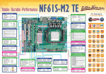
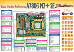
Back Panel I/O Connectors Printer Port Connector *Rückseiten-E/A *E/S du panneau arrière *I/O pannello posteriore *Panel trasero de E/S ﺥﺮج اﻟﻠﻮﺣﺔ اﻟﺨﻠﻔﻴﺔ/*ﻡﻨﺎﻓﺬ دﺥﻞ *Conector da para impressora *Druckeranschluss Anschluss *Connecteur de Port d’imprimante *Złącze Port drukarki *プリンタポートコネクタ *Connettore Porta stampante *ﻡﻨﻔﺬ ﻃﺎﺏﻌﺔ *Conector Puerto de impresora *Разъём Порт подключения принтера *Entradas/Saídas no painel traseiro *Back Panel I/O *Задняя панель средств вводавывода *背面パネルI/O PS/2 Mouse 10/100 Mbps LAN WWW.ANANDTECH.COM Line In/ Surround Line Out Mic In 1/ Bass/ Center 5.1-Channels HD Audio PS/2 Keyboard *Unterstützt High-Definition Audio / 5.1-Kanal-Audioausgabe *Prise en charge de l’audio haute définition / Sortie audio à 5.1 voies *Supporto audio High-Definition (HD) / Uscita audio 5.1 canali *Soporte de sonido de Alta Definición / Salida de sonido de 5.1 canales *Suporta a especificação High-Definition Audio / Saída de áudio de 5.1 canais *Obsługa High-Definition Audio / 5.1 kanałowe wyjście audio *Звуковая поддержка High-Definition / 5.1канальный звуковой выход *ハイデフィニションオーディオのサポート / 5.1 チャンネルオ ーディオアウト ﻗﻨﻮات ﻟﺨﺮج اﻟﺼﻮت5.1 /*ﺕﺪﻋﻢ ﺕﻘﻨﻴﺔ اﻟﺼﻮت ﻋﺎﻟﻲ اﻟﺘﻌﺮﻳﻒ ﻡﻦ 2 10 1 2 3 4 *NB Chipsatz: VIA P4M900 *NB Conjunto de chips: VIA P4M900 1 9 + + - + - On/Off System Fan Header *System-Lüfter-Sockel *Embase de ventilateur système *Collettore ventolina sistema 3 *Cabecera de ventilador de sistema *Conector da ventoinha do sistema 1 *Złącze główkowe wentylatora systemowego 1 Ground *Контактирующее приспособление 2 +12V вентилятора системы 3 FAN RPM rate sense *システムファンヘッダ *وﺹﻠﺔ ﻡﺮوﺣﺔ اﻟﻨﻈﺎم 3 4 1 2 3 4 +12V +12V Ground Ground CHIP iXBT HardOCP PC Stats Atomic AuJa Bjorn3D BUG CHIP CHIP CHIP CLUB OVERCLOCKER CHIP Custom PC Custom PC CRW CRW DOSV Power Report Guru3D Hartware HardwareZone Igromania Noticias 3D Noticias 3D OverclockerCafe PC Achat HardwareZone PC Lab PC Magazine PC Modding PC Modding PC Porfessionale PC Power Play PC WORLD PC WORLD PC WORLD PC WORLD PC WORLD TweakTown 3Ditalia *Набор микросхем: VIA P4M900 *チップセット: VIA P4M900 VIA P4M900 *ﻡﺠﻤﻮﻋﺔ اﻟﺸﺮاﺋﺢ DDR2 DIMM Slots Each DIMM supports 256MB/ 512MB/1GB/2GB DDR2 533/667 Front Panel Connector 8 16 1 NB Chipset : VIA P4M900 Left Channel Input Ground Ground Right Channel Input Power LED 2 *LGA 775 Intel Core2Duo/Pentium 4/Pentium D/Celeron D/Celeron 4xx Prozessoren *LGA 775 Processeurs Intel Core2Duo/Pentium 4/Pentium D/Celeron D/Celeron 4xx *LGA 775 Processore Intel Core2Duo/Pentium 4/Pentium D/Celeron D/Celeron 4xx *LGA 775 Procesador Intel Core2Duo/Pentium 4/Pentium D/Celeron D/Celeron 4xx *LGA 775 Processador Intel Core2Duo/ Pentium 4/Pentium D/Celeron D/Celeron 4xx *LGA 775 Procesor Intel Core2Duo/Pentium 4/Pentium D/Celeron D/Celeron 4xx *LGA 775 Процессор Intel Core2Duo/Pentium 4/Pentium D/Celeron D/Celeron 4xx LGA 775* ﻡﻌﺎﻟﺠﺎتIntel Core2Duo/Pentium 4/Pentium D/Celeron D/Celeron 4xx 1 Mic Left in 2 Ground 3 Mic Right in 4 GPIO 5 Right line in 6 Jack Sense 7 Front Sense 8 Key 9 Left line in 10 Jack Sense *Conector da unidade de disquetes *Złącze napędu dyskietek *Разъём НГМД *フロッピーコネクタ *Fronttafelanschluss *Connecteur du panneau avant Speaker *Connettore pannello frontale *Conector de panel frontal *Conector do painel frontal HDD LED *Złącze panela przedniego *Разъём на лицевой панели Reset *フロントパネルコネクタ *ﻡﻨﻔﺬ اﻟﻠﻮﺣﺔ اﻷﻡﺎﻡﻴﺔ USBX2 LGA 775 for Intel Core2Duo/Pentium 4/Pentium D/ Celeron D/Celeron 4xx Processor FSB: 533/800/1066 MHz Floppy Disk Drive Connector *Diskettenlaufwerkanschluss *Connecteur de disquette *Connettore floppy *Conector disco flexible *ﻡﻨﻔﺬ ﻡﺤﺮك أﻗﺮاص ﻡﺮﻥﺔ USBX2 Power Connector (4pin) CD-IN Connector *CD-IN-Anschluss *Connecteur d’entrée CD *Connettore CD-in 4 *Conector de entrada de CD *Conector para entrada de CDs *Złącze wejścia CD 1 *Разъём ввода для CD *CDインコネクタ CD-IN *ﻡﻨﻔﺬ VGA *Stromanschluss(4-polig) *Connecteur d’alimentation(4 broches) *Connettore alimentazione(4 pin) *Conector de alimentación(4 patillas) *Conector de alimentação(4 pinos) *Złącze zasilania (4 pinowe) *Разъем питания (4 вывод) *電源コネクタ(4ピン) (دﺑﻮس4)*ﻡﻨﻔﺬ ﺕﻮﺹﻴﻞ اﻟﻄﺎﻗﺔ Front Audio Connector *Front-Audioanschluss *Connecteur Audio du panneau avant *Connettore audio frontale 1 *Conector de sonido frontal *Conector de áudio frontal *Przednie złącze audio 9 *Входной звуковой разъём *フロントオーディオコネクタ *ﻡﻨﻔﺬ اﻟﺼﻮت اﻷﻡﺎﻡﻲ COM1 SATA Connectors *SATA-Anschluss *Connecteur SATA *Connettore SATA *Conector SATA *Conector SATA *Złącze SATA *Разъём SATA *SATAコネクタ SATA *ﻡﻨﻔﺬ Clear CMOS Header *“CMOS löschen”-Sockel *Embase d’effacement CMOS *Collettore cancellazione CMOS *Cabecera de borrado de CMOS *Conector para limpeza do CMOS *Złącze główkowe kasowania CMOS *Открытое контактирующее приспособление CMOS *CMOSクリアヘッダ CMOS *وﺹﻠﺔ ﻡﺴﺢ 1 Pin 1-2 Close: PCI-Express x1 Slot *PCI Express x1-Steckplatz *Fente PCI Express x1 *Alloggio PCI Express x1 *Ranura PCI express x1 PCI Express x1*ﻓﺘﺤﺔ *Ranhura PCI Express x1 *Gniazdo PCI Express x1 *Слот PCI Express x1 *PCI Express x1スロット PCI Slots *PCI-Steckplatz *Fente PCI *Alloggio PCI *Ranura PCI *Ranhura PCI *Gniazdo PCI *Слот PCI *PCIスロット PCI *ﻓﺘﺤﺔ Power Connector (24pin) *Stromanschluss(24-polig) *Connecteur d’alimentation (24 broches) *Connettore alimentazione(24 pin) *Conector de alimentación (24 patillas) *Conector de alimentação (24 pinos) *Złącze zasilania (24 pinowe) *Разъем питания (24 вывод) *電源コネクタ(24ピン) (دﺑﻮس24)*ﻡﻨﻔﺬ ﺕﻮﺹﻴﻞ اﻟﻄﺎﻗﺔ IDE Connectors *IDE-Anschluss *Connecteur IDE *Connettore IDE *Conector IDE *Conector IDE *Złącze IDE *Разъём IDE *IDEコネクタ IDE*ﻡﻨﻔﺬ Normal Operation 3 (default) 1 3 Pin 2-3 Close: Clear CMOS data USB 2.0 Connectors *USB 2.0-Anschluss *Connecteur USB 2.0 *Connettore USB 2.0 *Conector USB 2.0 *Conector USB 2.0 *Złącze USB 2.0 *USB 2.0-разъём *USB 2.0コネクタ USB 2.0*ﻡﻨﻔﺬ PCI-Express x16 Slot *PCI Express x16-Steckplatz *Fente PCI Express x16 *Alloggio PCI Express x16 *Ranura PCI express x16 PCI Express x16*ﻓﺘﺤﺔ *Ranhura PCI Express x16 *Gniazdo PCI Express x16 *Слот PCI Express x16 *PCI Express x16スロット *DDR2 DIMM-Steckplätze Jeder DIMM unterstützt 256MB/512MB/1GB/2GB DDR2 533/667 *Fentes DDR2 DIMM Chaque DIMM prend en charge des DDR2 533/667 de 256Mo/ 512Mo/1Go/2Go *Alloggi DIMM DDR2 Ciascun DIMM supporta DDR2 533/667 256MB/512MB/1GB/2GB *Ranuras DIMM DDR2 Cada DIMM admite DDR2 533/667 de 256MB/512MB/1GB/2GB *Ranhuras DIMM DDR2 Cada módulo DIMM suporta uma memória DDR2 533/667 de 256MB/512MB/1GB/2GB *Gniazda DDR2 DIMM Każde gniazdo DIMM obsługuje moduły 256MB/512MB/1GB/2GB DDR2 533/667 *Слоты DDR2 DIMM Каждый модуль DIMM поддерживает 256МБ/512МБ/1ГБ/2ГБ DDR2 533/667 *DDR2 DIMMスロット 各DIMMは 256MB/512MB/1GB/2GB DDR2 533/667をサポート DDR2 DIMM *ﻓﺘﺤﺔ ﺕﺪﻋﻢ آﻞ ﻓﺘﺤﺔDIMM ﺕﺪﻋﻢ ذاآﺮة ﻡﻦ ﻥﻮعDDR2 533/667 ﺳﻌﺔ ﺑﺎﻳﺖ256 ﻡﻴﺠﺎ ﺑﺎﻳﺖ/512 ﺝﻴﺠﺎ2/ ﺝﻴﺠﺎ ﺑﺎﻳﺖ1ﻡﻴﺠﺎ ﺑﺎﻳﺖ و CPU Fan Header *CPU-Lüfter-Sockel *Embase de ventilateur UC *Collettore ventolina CPU 4 *Cabecera de ventilador de CPU *Conector da ventoinha da CPU *Złącze główkowe wentylatora 1 procesora *Контактирующее приспособление вентилятора центрального процессора *CPUファンヘッダ *وﺹﻠﺔ ﻡﺮوﺣﺔ وﺣﺪة اﻟﻤﻌﺎﻟﺠﺔ اﻟﻤﺮآﺰﻳﺔ 1 Ground 2 +12V 3 FAN RPM rate sense 4 Smart Fan Control Step 1:CPU Installation LGA 775 CPU Socket Supports Intel Core2Duo/Pentium 4/ Pentium D/Celeron D/Celeron 4xx processor up to 3.8 GHz (It is recommended to use processors with 95W power consumption.) FSB: 533/800/1066 MHz Package Checklist Step 4: Hold the CPU down firmly, and then lower the lever to locked the position. ▲ Installation Guide x 1 ▲ HDD Cable x 1 ▲ Fully Setup Driver CD x 1 (full version manual files inside) ▲ Rear I/O Panel x 1 ▲ Serial ATA Cable x 1 (optional) ▲ FDD Cable x 1 (optional) ▲ Serial ATA Power Cable x 1 (optional) ▲ Parallel Printer Cable x1 (optional) Note: The package contents may differ by area or your motherboard version. Serial NO. Definition P4M90M7C-xx 70xxxxxxx00001 PCB Version NO. Step 5: Place the CPU fan assembly on top of the installed CPU and make sure that the four fasteners match the motherboard holes. Orient the assembly and make the fan cable is closest to the CPU fan connector. Step 1: Remove the protection cap from the CPU socket and keep the cap well. Serial NO. of Production Manufacturer’s Internal Part NO. CAUTION Our RMA policy only accepts the mainboard comes with the cap on the CPU socket, so please keep the protection cap well after installation. We will not be responsible for any damage to the pin-leg of the CPU socket resulting from misplacement/loss/incorrect removal of the protection cap. Q&A of Technical Support Q: How to get a quick response for my request on technical support? A: Please carry out a simple troubleshooting before sending “Technical Support Form” on our website. Q: Is the motherboard dead? Do I need to return it to where I bought from or go through an RMA process? A: After you had gone through the troubleshooting procedures, yet the problem still exists, or you find an evident damage on the motherboard. Please contact your reseller shop to get the RMA service. Step 2: Pull the socket locking lever out from the socket and then raise the lever up to a 90-degree angle. Copyright and Warranty Notice Step 6: Press down two fasteners at one time in a diagonal sequence to secure the CPU fan assembly in place. CPU installation completes. Step 3: Look for the triangular cut edge on socket, and the golden dot on CPU should point forwards this triangular cut edge. The CPU will fit only in the correct orientation. The information in this document is subject to change without notice and does not represent a commitment on part of the vendor, who assumes no liability or responsibility for any errors that may appear in this manual. No warranty or representation, either expressed or implied, is made with respect to the quality, accuracy or fitness for any particular part of this document. In no event shall the manufacturer be liable for direct, indirect, special, incidental or consequential damages arising from any defect or error in this manual or product. Product names appearing in this manual are for identification purpose only and trademarks and product names or brand names appearing in this document are the property of their respective owners. This document contains materials protected under International Copyright Laws. All rights reserved. No part of this manual may be reproduced, transmitted or transcribed without the expressed written permission of the manufacturer and authors of this manual. If you do not properly set the motherboard settings, causing the motherboard to malfunction or fail, we cannot guarantee any responsibility. Note: Do not forget to connect the CPU fan connector. For further information, please refer to Step 3:Power Connection. 50-RP4M90M7C-Q-B1 Step 2:Memory Installation DDR2 DIMM Slot x2 Supports DDR2 533/667 Each DIMM supports 256MB / 512MB / 1GB / 2GB DDR2 Max Memory Capicity is 4GB Step 3:Power Connection Clear CMOS Header CPU Fan Power (JCFAN1) JCFAN1 supports 4-pin head connector. When connecting with wires onto connectors, please note that the black wire is Ground and should be connected to pin#1(Ground). The Occasion to Clear CMOS 24-pin ATX Power (JATXPWR1) JATXPWR1 is the main power supply connector located along the edge of the board next to the DIMM slots. Firmly plug the power supply cable into the connector and make sure it is secure. 3. The CMOS data becomes corrupted. Driver & Manual 1. Forgot the supervisor/user password preset in the BIOS menu. 2. Unable to boot up the system because the CPU clock was incorrectly set in the BIOS menu. After you installed your operating system, please insert the Fully Setup Driver CD into your optical drive and install the driver for better system performance. You will see following window after you insert the CD. Click on Driver to start the process of driver installation. Clear CMOS Header (CMOS1) 1 Pin 1-2 Close: Normal Operation Step 1: Unlock a DIMM slot by pressing the retaining clips outward. Align a DIMM on the slot such that the notch on the DIMM matches the break on the Slot. 3 (default) 1 3 4-pin ATX Power (JATXPWR2) JATXPWR2, the 4-pin ATX 12V power connection, is used to provide power to the CPU. Align the pins to the connector and press firmly until seated. Step 2: Insert the DIMM vertically and firmly into the slot until the retaining chip snap back in place and the DIMM is properly seated. Installation Complete Follow the three steps to finish CPU, memory, and power installation, and the whole motherboard assembly should looks like this picture. Pin 2-3 Close: Clear CMOS data The installation program will detect your system to find out the driver needed to be installed. Clear CMOS Procedure 1. Remove AC power line. 2. Set the jumper to “Pin 2-3 close”. 3. Wait for five seconds. 4. Set the jumper to “Pin 1-2 close”. 5. Power on the AC. 6. Reset your desired password or clear the CMOS data. Click on Install and the program will begin to install the proper driver for your system. NOTE: How to Setup Jumpers When the driver installation completes, there will be a dialogue appears asking you to restart the system. Please click on YES to restart your computer. The illustration shows how to set up jumpers. When the jumper cap is placed on pins, the jumper is “close”, if not, that means the jumper is “open”. For more information of the mainboard setup and BIOS setup, please refer to the full version manual in the setup CD. In the Setup CD auto-run program, click on Manual and then click on Mainboard User Manual or BIOS User Manual. Pin Opened Pin Closed Pin 1-2 Closed