1
GDX-350 Sensor Transmitter
Instruction 5600-9001
Installation • Operation • Maintenance
Rev. 2 – October 2012
Product Leadership • Training • Service • Reliability
GDX-350 Sensor Transmitter
WARRANTY
Bacharach, Inc. warrants to Buyer that at the time of delivery this Product will be free from defects in material and
manufacture and will conform substantially to Bacharach Inc.'s applicable specifications. Bacharach's liability and
Buyer's remedy under this warranty are limited to the repair or replacement, at Bacharach's option, of this Product or
parts thereof returned to Seller at the factory of manufacture and shown to Bacharach Inc.'s reasonable satisfaction
to have been defective; provided that written notice of the defect shall have been given by Buyer to Bacharach Inc.
within two (2) years after the date of delivery of this Product by Bacharach, Inc.
Bacharach, Inc. warrants to Buyer that it will convey good title to this Product. Bacharach's liability and Buyer's
remedy under this warranty of title are limited to the removal of any title defects or, at the election of Bacharach, to
the replacement of this Product or parts thereof that are defective in title.
The warranty set forth in paragraph 1 does not apply to parts the Operating Instructions designate as having a limited
shelf-life or as being expended in normal use (e.g., filters).
THE FOREGOING WARRANTIES ARE EXCLUSIVE AND ARE GIVEN AND ACCEPTED IN LIEU OF (I) ANY AND
ALL OTHER WARRANTIES, EXPRESS OR IMPLIED, INCLUDING WITHOUT LIMITATION THE IMPLIED
WARRANTIES OF MERCHANTABILITY AND FITNESS FOR A PARTICULAR PURPOSE: AND (II) ANY
OBLIGATION, LIABILITY, RIGHT, CLAIM OR REMEDY IN CONTRACT OR TORT, WHETHER OR NOT ARISING
FROM BACHARACH'S NEGLIGENCE, ACTUAL OR IMPLIED. The remedies of the Buyer shall be limited to those
provided herein to the exclusion of any and all other remedies including, without limitation incidental or consequential
damages. No agreement varying or extending the foregoing warranties, remedies or this limitation will be binding
upon Bacharach, Inc. unless in writing, signed by a duly authorized officer of Bacharach.
Register your warranty by visiting
www.MyBacharach.com
NOTICE
Product improvements and enhancements are continuous; therefore the specifications and information
contained in this document may change without notice.
Bacharach, Inc. shall not be liable for errors contained herein or for incidental or consequential damages
in connection with the furnishing, performance, or use of this material.
No part of this document may be photocopied, reproduced, or translated to another language without the
prior written consent of Bacharach, Inc.
Copyright © 2012, Bacharach, Inc., All Rights Reserved
®
BACHARACH is a registered trademark of Bacharach, Inc. All other trademarks, trade names,
service marks and logos referenced herein belong to their respective owners.
2
P/N: 5600-9001 Rev 2
GDX-350 Sensor Transmitter
TABLE OF CONTENTS
1.
OVERVIEW ........................................................................................................................................... 5
1.1.
Stand-alone and Wired Networks ............................................................................................ 5
1.2.
RF Wireless Networks ............................................................................................................. 6
1.3.
The RF Transmitter and Client/Server Wireless Networks ...................................................... 7
1.3.1 Radio Status Icons (
) .................................................................. 7
1.3.2 RF Comm Cycle and Conserving Battery Life.............................................................. 8
1.3.3 RF BATTERY I/O PCB WITH POWER SWITCH ......................................................... 8
1.3.4 900 MHz RF Module ..................................................................................................... 9
1.4.
Safety Information – Read Before Installation and Applying Power ...................................... 10
1.5.
Ordering Information .............................................................................................................. 11
1.6.
Replacement Parts and Accessories ..................................................................................... 13
1.7.
Calibration Gas ...................................................................................................................... 14
1.8.
System Design Specifications ............................................................................................... 14
1.9.
General Specifications ........................................................................................................... 15
1.10. Sensor Specifications ............................................................................................................ 16
2.
INSTALLATION INSTRUCTIONS ...................................................................................................... 17
2.1.
Sensor Location ..................................................................................................................... 17
2.2.
Mounting the Enclosure ......................................................................................................... 17
2.2.1 Stand-alone and Wired Networks ............................................................................... 17
2.2.2 RF Wireless Networks ................................................................................................ 18
Transmission Range: 4-20mA Signals ................................................................................. 20
2.3.
2.4.
Transmission Range: RF Antenna Signals ........................................................................... 20
2.5.
Antenna Selection and Location ............................................................................................ 21
2.6.
Water Proofing Antenna Connection ..................................................................................... 22
2.7.
System Grounding ................................................................................................................. 22
2.8.
3-Wire 4-20 mA Mode Installation ......................................................................................... 22
2.9.
Alarms/RS-485 Modbus Option Installation ........................................................................... 23
2.10. Isolated 4-20 mA Output Option ............................................................................................ 26
2.11. Sensor Installation ................................................................................................................. 26
3.
INITIAL START-UP ............................................................................................................................. 28
3.1.
Model Name ........................................................................................................................... 28
3.2.
Initial Toxic/Oxygen Sensor Monitor Start-Up........................................................................ 28
3.3.
Initial Toxic/Oxygen Sensor Monitor “Span” Check ............................................................... 28
4.
OPERATING INSTRUCTIONS ........................................................................................................... 29
4.1.
Routine Sensor Calibrations .................................................................................................. 29
4.2.
Alarm Operation ..................................................................................................................... 31
4.3.
Alarm 3 – Understanding Fault/Level Operation ................................................................... 31
5.
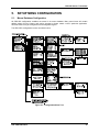
SETUP MENU CONFIGURATION ..................................................................................................... 33
5.1.
Menus Database Configuration ............................................................................................. 33
5.2.
Configuration Using the Magnetic Wand ............................................................................... 35
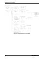
5.3.
System Configuration Menus ................................................................................................. 35
5.4.
Alarm Settings ........................................................................................................................ 37
5.5.
Relay Configuration (If Equipped) .......................................................................................... 39
5.6.
Sensor Information ................................................................................................................. 39
5.7.
Clock/Delay Setup ................................................................................................................. 40
5.8.
Communications Setup (RF Communications)...................................................................... 40
5.9.
Base Stations ......................................................................................................................... 42
5.10. System Security ..................................................................................................................... 43
5.11. LCD Contrast Adjustment ...................................................................................................... 43
5.12. HELP Screen ......................................................................................................................... 44
P/N: 5600-9001 Rev 2
3
GDX-350 Sensor Transmitter
5.13.
5.14.
5.15.
5.16.
6.
Diagnostics ............................................................................................................................ 44
RS-485/Modbus Setup........................................................................................................... 44
Modbus Register and Function Code Summary .................................................................... 45
System Security ..................................................................................................................... 49
SERVICE CENTER ............................................................................................................................. 49
∇ ∇ ∇
4
P/N: 5600-9001 Rev 2
GDX-350 Sensor Transmitter
1.
OVERVIEW
1.1.
Stand-alone and Wired Networks
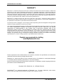
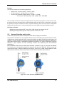
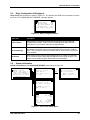
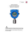
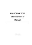
The GDX-350 is a fixed-point monitor designed to provide continuous monitoring of hazardous gases in
the workplace. Monitored values are displayed in their engineering units as well as graphically such as
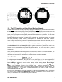
bar graphs or 30-minute trends (see Figure 1-1).
Figure 1-1: Engineering Units Data Displays: Bar Graph (Left), 30-Minute Trend (Right)
Input types include electrochemical toxic and oxygen sensors, catalytic bead combustible sensors, MOS
solid-state sensors, as well as various millivolt, volt and 4-20 mA inputs. Sensors supplied by the factory
include an 8-wire Smart Sensor interface capable of configuring data uploads to the GDX-350.
Traditional 3-wire Simple sensors, without the smart interface, are also supported by the GDX-350. Its
advanced microcontroller electronics and superior graphic LCD operator interface offer enhanced
diagnostics and fault analysis not possible in competing products. The GDX-350 provides a standard
4-20 mA output signal for connection to control systems or other alarm instrumentation. Available options
include an Alarm Relay/RS-485-Modbus board or an isolated 4-20 mA output. Non-volatile memory
retains all configuration data during power interruptions. The magnetic, non-intrusive calibration can be
easily performed by a single person without opening the enclosure. A standard Real Time Clock and
Calendar feature allows data logging of calibrations and alarm events for recall to the LCD readout or
over the serial port.
Only periodic calibration checks are needed to assure dependable performance. The operator interface
is very intuitive with the LCD displaying data both graphically as bar-graphs/trends as well as in
engineering units (Figure 1-1). Additional features include:
•
•
•
•
•
•
•
•
•
No potentiometer or jumper settings required. All setup is completed through display menus
accessed via the LCD/magnetic keypad operator interface without opening the enclosure.
Field adjustable alarm levels may be high, low, fault, fail-safe, latching and acknowledgeable.
New alarms cause front LEDs to flash and become steady after acknowledgement.
CAL MODE advises when to apply gas during calibrations.
One half-hour trend screen shows rate of change of gas exposures.
Sensor life bar-graph automatically updates after each SPAN calibration.
Modular design allows for efficient installation as well as plug in sensors that allow a change in target
gas after installation
New smart sensors are recognized by the GDX-350 and prompt users to either upload new
configuration data or continue with data from the previous smart sensor.
Sensors are industry proven for fast response and long life.
P/N: 5600-9001 Rev 2
5
GDX-350 Sensor Transmitter
1.2.
RF Wireless Networks
IMPORTANT: This section describes GDX-350 RF toxic / oxygen monitors equipped with
the RF Wireless Interface and RF firmware. This battery powered device has no external
power or signal wiring and is limited to self powered electrochemical sensors for toxic and
oxygen measurements. Gas values are displayed in their engineering units as well as
graphically as bar graphs or 30-minute trends. Flashing front panel LEDs notify personnel
when alarm levels have been reached. Periodic calibration checks are needed to assure
dependable performance.
The RF version of the GDX-350 functions on a license free 900MHz or 2.4GHz wireless Client / Server
networks and transmits monitored data to GDA-400 and GDA-1600 controllers. Controllers must be
equipped with the matching RF wireless modem and appropriate antenna to receive the transmissions.
Up to sixteen GDX-350 wireless monitors may communicate to one GDA-1600 and up to four to a GDA400. Wireless networks requiring more than 16 points may consist of multiple controllers.
Advanced microcontroller electronics and superior graphic LCD operator interface offers enhanced
diagnostics and fault analysis not possible in competing products. Non-volatile memory retains all
configuration data during power interruptions. The magnetic keypad allows non-intrusive calibrations be
performed by one person without opening the enclosure. A “real time clock & calendar” feature allows
logging of calibrations, alarm trips, communication faults and other events for review on the LCD readout.
Compatible sensors include an 8-wire Smart Sensor interface capable of configuration data uploads to
the monitor. Traditional Simple sensors without the smart interface are also supported. A separate PC
compatible USB Interface device allows Smart sensors to be loaded with configuration variables via a PC
and upload this data to the GDX-350. This configuration data includes alarm set points, range, target gas,
calibration constants and other variables required to match a specific application. For Simple sensors
without the smart interface, the USB device allows direct GDX-350 configuration from a PC.
Additional features include:
•
•
•
•
•
•
•
•
•
•
6
On screen radio status icons indicate “Server In Range”, “Server Out of Range”, “Server
Previously Out of Range” and “Low Battery” conditions.
No potentiometer or jumper settings required. All setup is with menus accessed via the LCD /
magnetic keypad operator interface without opening the enclosure.
Field adjustable alarm levels flash front panel LED indicators for HIGH, WARN, FAIL conditions.
Alarm relays are not available with this low power model.
CAL MODE provides on-screen prompts when to apply cal gas during calibrations.
“Sensor life” bar-graph updates after each SPAN calibration indicating when to replace old
sensors.
Half hour trend screen shows rate of change of gas exposures.
Modular design affords efficient installation and plug in sensors allow changing target gases even
after installation.
New smart sensors are recognized by the GDX-350 which prompts users to either upload new
configuration data or continue with data from the previous smart sensor.
Missing sensors trip the FAIL alarm.
Compatible sensors are industry proven for fast response and long life.
P/N: 5600-9001 Rev 2
GDX-350 Sensor Transmitter
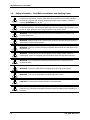
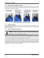
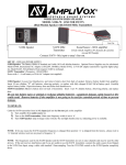
Figure 1-2: Data Displays (RF Version) SHOWING Radio Status
1.3.
The RF Transmitter and Client/Server Wireless Networks
Wireless transceivers utilize a FHSS (Frequency Hopping Spread Spectrum) Server-Client network where
multiple clients synchronize their frequency hopping to a single server. The Server transmits a beacon at
the beginning of every frequency hop (50 times per second). Client transceivers listen for this beacon and
upon receiving it synchronize their hopping with the Server. Since RF GDX-350s are powered by a small
battery, much care is taken to reduce power consuming RF transmissions to a minimum. For this reason
RF-configured GDX-350s are unsuitable for Server operation and are always Clients.
Each GDX-350 wireless “broadcast” includes 10-bit monitored gas value, battery voltage and a status
byte. This proprietary wireless protocol interfaces only to GDA-400 and GDA-1600 controllers.
Controllers are capable of functioning as Clients or Servers, but only one Server is allowed per wireless
network. Multiple controllers may receive the same transmissions from RF-configured GDX-350s, but only
one controller per wireless network may be configured as the Server.
Each transceiver on a wireless network must have its RADIO SETUP menus configured to share the
same Hop Channel (0-32) and System ID (0-255) in order to communicate. There should never be two
servers with the same Hop Channel / System ID settings in the same coverage area as the interference
between the two servers will severely hinder RF communications. The Server must be in a powered
location and should be centrally located since all Clients must receive the server’s beacon in order to
communicate.
Correct planning and design of wireless systems are imperative for ensuring a successful installation. It is
highly recommended that a site drawing indicating location of monitors and base station, line of site
obstructions, and sources of RF interference be submitted when requesting a quotation.
1.3.1 Radio Status Icons (
)
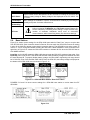
Figure 2-1 shows the data displays and identifies “radio status” (RS) icons which appear on the LCD of
RF-configured GDX-350s. RS icons, along with the TXD led (see Figure 1-2), are useful diagnostic tools
for evaluating RF communication. Status conditions indicated by the RS icon are Sleep Mode - Zzz’s,
(server’s beacon received at most recent attempt), Server Out of Range Server In Range (server’s beacon not received at most recent attempt), Server Previously Out of Range and Low
. The Server “Previously Out of Range” icon is useful in determining if intermittent
Battery communication failures are a result of this monitor having problems receiving the Server’s beacon. The
duration and frequency of “out of range” conditions are stored in the Event Log table. Low Battery
conditions also flash the FAIL LED.
It is important to understand RS icons only update as the TXD LED flashes indicating an RF transmission
has occurred. The adjustable (see Wakeup Time menu) RF transmission rates are typically each 5minutes, but increase to each 6-seconds during alarm conditions.
P/N: 5600-9001 Rev 2
7
GDX-350 Sensor Transmitter
1.3.2 RF Comm Cycle and Conserving Battery Life
Most of the GDX-350’s battery power is consumed as the radio communicates to the wireless network.
Each Comm cycle consists of the following operations: Awake the radio in receive mode; listen for the
”; transmit data
Server’s beacon; synchronize to the Server’s hopping frequency to become “In Range
packet out the antenna and return to sleep mode. This sequence takes from 0.25 to 1 second to
complete. If the radio fails to synchronize hopping upon the initial attempt, it waits 6 seconds and tries
again, then waits 6 seconds and tries once more. If the third attempt fails, the “Out of Range ” icon
appears and the GDX-350 returns to its Comm cycle. Out of Range will also be logged into the Event
Log. Transmit power levels are adjustable (900MHx models only) and the lower the power setting the
longer the battery will last.
Every 6-seconds, the monitor performs a “sniff test” to detect level of target gas present at the sensor. At
each “sniff test”, the Zzz’s “Sleep Mode” icon is briefly replaced by an RS icon. At this time the readout
updates to indicate gas value measured at the “sniff test.” The radio stays OFF if the gas value does not
trip A1 or A2 alarms. Except when the Wakeup Time menu expires (maximum of 5-minutes) the radio
turns on, receives the Server’s beacon, and transmits its data. These routine transmissions allow the
controllers to confirm a good wireless comm link even when no alarms exist. If A1 or A2 alarms do exist
during the “sniff test”, the radio wakes, receives the Server’s beacon, and transmits its data immediately.
The following list identifies each of the conditions that cause the radio to transmit:
•
Every 5-minutes (or faster depending upon Wakeup Time menu) when there is no A1 or A2
alarm.
IMPORTANT: The receiving controller reports “Comm Error” if the monitor does not
reply for periods of greater than 18-minutes. A3 and FAIL alarms do not increase radio
transmission rates.
•
•
•
Every 6-seconds if there is an A1 or A2 level alarm.
Upon entry into CAL MODE a 75 counts value (-15.6% FS) is transmitted. Receivers indicate “IN
CAL” when 75 counts is the input for a channel (200 to 1000 counts represents 0 to 100% of full
scale).
Upon ENTRY into CAL PURGE a 200 counts value (0% FS) is transmitted.
NOTE: To prevent A1 & A2 low trip alarms, oxygen ranges transmit 20.9% readings upon entry
into CAL PURGE.
•
Holding the magnet to the UP key for >8 seconds forces a transmission of the current reading
value.
1.3.3 RF BATTERY I/O PCB WITH POWER SWITCH
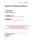
The RF electronics consists of the lower Battery I/O PCB (Figure 1-3) connected by a cable to the upper
Display assembly with RF Module PCB (Figure 1-4). The 3.6 volt lithium ‘D’ cell battery will continuously
power the unit for up to one year and may be replaced by following the procedure in Figure 1-3.
Power switch (SW1), on the Battery PCB, applies battery power to the RF monitor. SW1 should be OFF if
the monitor is to be out of service for long periods.
IMPORTANT: Do not turn SW1 ON until the controller designated as Server is fully
operational and ready to communicate to the RF-equipped GDX-30s. Battery life is
reduced if the RF-equipped GDX-30 is on for long periods while unable to communicate to
the Server controller.
IMPORTANT: DO NOT ATTEMPT TO CHARGE THIS BATTERY OR REPLACE WITH
ANY OTHER THAN THE APPROPRIATE PART FROM BACHARACH.
8
P/N: 5600-9001 Rev 2
GDX-350 Sensor Transmitter
Figure 1-3: Battery I/O PCB
1.3.4 900 MHz RF Module
The RF-equipped GDX-350’s RF module mounts “piggy back” to the back of the Display assembly as
shown in Figure 1-4. The MMCX RF connector connects to the antenna fitting’s pigtail coax cable. There
is also a slender 4 conductor cable between the RF Module PCB and the battery I/O PCB bolted to the
bottom of the enclosure.
Figure 1-4: RF Module PCB
P/N: 5600-9001 Rev 2
9
GDX-350 Sensor Transmitter
1.4.
Safety Information – Read Before Installation and Applying Power
IMPORTANT: Users should have a detailed understanding of GDX-350 operating and
maintenance instructions. Use the GDX-350 only as specified in this manual otherwise
the detection of gases and resulting protection provided may be impaired. Read the
following WARNINGS prior to use.
WARNING: Calibrate with known target gas at start-up and check on a regular schedule,
at least every 90 days. More frequent inspections are encouraged to spot problems such
as dirt, oil, paint, grease or other foreign materials on the sensor head.
WARNING: Do not use the GDX-350 if its enclosure is damaged or cracked or has
missing components.
WARNING: Make sure the cover, internal PCBs, antenna, and field wiring connections
are securely in place before operation.
WARNING: Use only a sensor assembly compatible with the GDX-350 and approved by
Bacharach, Inc.
WARNING: Periodically test for correct operation of the system’s alarm events by
exposing the monitor to a targeted gas concentration above the High Alarm set point.
WARNING: Do not expose the GDX-350 to electrical shock or continuous severe
mechanical shock.
WARNING: Protect the GDX-350 from dripping liquids and high power sprays.
WARNING: Use only for applications described within this manual.
CAUTION: Do not paint the sensor assembly or the transmitter.
CAUTION: For safety reasons this equipment must be operated and serviced by qualified
personnel only. Read and understand instruction manual completely before operating or
servicing.
10
P/N: 5600-9001 Rev 2
GDX-350 Sensor Transmitter
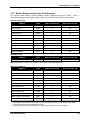
1.5.
Ordering Information
Transmitter
Description
Part
Number
5600-301x
GDX-350 CO
5601-301x
5600-302x
GDX-350 H2S
5601-302x
5600-303x
GDX-350 O2
5601-303x
5600-304x
GDX-350 NO2
5601-304x
5600-305x
GDX-350 NH3
5601-305x
5600-306x
GDX-350 SO2
5601-306x
P/N: 5600-9001 Rev 2
Options
x=1
3-wire base w/ 4-20 mA output
x=2
3-wire base w/ 4-20 mA output and Modbus
x=1
2-wire base
x=8
2-wire base w/ 900 MHz wireless
x=9
2-wire base w/ 2.4 GHz wireless
x=1
3-wire base w/ 4-20 mA output
x=2
3-wire base w/ 4-20 mA output and Modbus
x=1
2-wire base
x=8
2-wire base w/ 900 MHz wireless
x=9
2-wire base w/ 2.4 GHz wireless
x=1
3-wire base w/ 4-20 mA output
x=2
3-wire base w/ 4-20 mA output and Modbus
x=1
2-wire base
x=8
2-wire base w/ 900 MHz wireless
x=9
2-wire base w/ 2.4 GHz wireless
x=1
3-wire base w/ 4-20 mA output
x=2
3-wire base w/ 4-20 mA output and Modbus
x=1
2-wire base
x=8
2-wire base w/ 900 MHz wireless
x=9
2-wire base w/ 2.4 GHz wireless
x=1
3-wire base w/ 4-20 mA output
x=2
3-wire base w/ 4-20 mA output and Modbus
x=1
2-wire base
x=8
2-wire base w/ 900 MHz wireless
x=9
2-wire base w/ 2.4 GHz wireless
x=1
3-wire base w/ 4-20 mA output
x=2
3-wire base w/ 4-20 mA output and Modbus
x=1
2-wire base
x=8
2-wire base w/ 900 MHz wireless
x=9
2-wire base w/ 2.4 GHz wireless
11
GDX-350 Sensor Transmitter
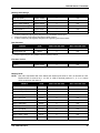
Transmitter
Description
Part
Number
5600-307x
GDX-350 PH3
5601-307x
5600-311x
GDX-350 H2
5601-311x
GDX-350 CH4
(Catalytic)
5600-320x
GDX-350 CH4
(IR)
5600-321x
GDX-350 CO2
5600-322x
GDX-350 C3H3
(IR)
5600-323x
12
Options
x=1
3-wire base w/ 4-20 mA output
x=2
3-wire base w/ 4-20 mA output and Modbus
x=1
2-wire base
x=8
2-wire base w/ 900 MHz wireless
x=9
2-wire base w/ 2.4 GHz wireless
x=1
3-wire base w/ 4-20 mA output
x=2
3-wire base w/ 4-20 mA output and Modbus
x=1
2-wire base
x=8
2-wire base w/ 900 MHz wireless
x=9
2-wire base w/ 2.4 GHz wireless
x=1
3-wire base w/ 4-20 mA output
x=2
3-wire base w/ 4-20 mA output and Modbus
x=1
3-wire base w/ 4-20 mA output
x=2
3-wire base w/ 4-20 mA output and Modbus
x=1
3-wire base w/ 4-20 mA output
x=2
3-wire base w/ 4-20 mA output and Modbus
x=1
3-wire base w/ 4-20 mA output
x=2
3-wire base w/ 4-20 mA output and Modbus
P/N: 5600-9001 Rev 2
GDX-350 Sensor Transmitter
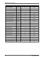
1.6.
Replacement Parts and Accessories
Part Number
Description
5600-0004
GDX Calibration Cup/Sample Draw Adaptor
5600-0003
GDX Splash Guard/Remote Cal-Cup
0024-7059
Calibration Kit – Regulator, Tubing, and Carrying Case (no gas included)
5600-5010
CO
Uncalibrated Sensor Module
5600-6010
CO
Pre-Calibrated Smart Sensor Module
5600-5020
H2S
Uncalibrated Sensor Module
5600-6020
H2S
Pre-Calibrated Smart Sensor Module
5600-5030
O2
Uncalibrated Sensor Module
5600-6030
O2
Pre-Calibrated Smart Sensor Module
5600-5040
NO2
Uncalibrated Sensor Module
5600-6040
NO2
Pre-Calibrated Smart Sensor Module
5600-5050
NH3
Uncalibrated Sensor Module
5600-6050
NH3
Pre-Calibrated Smart Sensor Module
5600-5060
SO2
Uncalibrated Sensor Module
5600-6060
SO2
Pre-Calibrated Smart Sensor Module
5600-5070
PH3
Uncalibrated Sensor Module
5600-6070
PH3
Pre-Calibrated Smart Sensor Module
5600-5200
CH4 (CAT)
Uncalibrated Sensor Module
5600-6200
CH4 (CAT)
Pre-Calibrated Smart Sensor Module
5600-5210
CH4 (IR)
Uncalibrated Sensor Module
5600-6210
CH4 (IR)
Pre-Calibrated Smart Sensor Module
5600-5220
CO2
Uncalibrated Sensor Module
5600-6220
CO2
Pre-Calibrated Smart Sensor Module
5600-5110
H2
Uncalibrated Sensor Module
5600-6110
H2
Pre-Calibrated Smart Sensor Module
5600-5330
C3H8
Uncalibrated Sensor Module
5600-6330
C3H8
Pre-Calibrated Smart Sensor Module
P/N: 5600-9001 Rev 2
13
GDX-350 Sensor Transmitter
1.7.
Calibration Gas
Part Number
1.8.
Gas Name
Chemical Formula
Concentration
0051-4000
Ammonia
NH3
25 PPM
0051-4028
Propane
C3H8
25% LEL
0051-4031
Methane
CH4
25% LEL
0051-4010
Carbon Dioxide
CO2
2.50%
0051-4052
Phosphine
PH3
1 PPM
0051-4040
Hydrogen
H2
0051-4048
Nitrogen Dioxide
NO2
5 PPM
0051-4075
Sulfur Dioxide
SO2
5 PPM
0051-4044
Hydrogen Sulfide
H2S
25 PPM
0051-4049
Oxygen
O2
20.9%
0051-4025
Carbon Monoxide
CO
100 PPM
100 PPM
System Design Specifications
Category
Supply Voltage
Power
Consumption
System Design Specification
10 to 30 volts
•
With a typical 0.5 watt Bridge Sensor: 100 mA @ nominal 24 VDC
•
Relays/RS-485 Modbus Option Board: 40 mA per relay (120 mA total with all 3
energized); RS-485 use adds 20 mA
Memory
Non-volatile E2 memory retains configuration values on power outages.
Loop
Resistance
750 ohms maximum (at nominal 24 VDC power)
Three configurable form C (SPDT) relays rated for 5 amp at 30 VDC or 240 VAC
RESISTIVE.
Relays
(Optional)
Relay 1 and Relay 2 level alarms may be configured for HIGH or LOW trip, for
normally energized (Failsafe) or normally de-energized and for latching or nonlatching.
Relay 3 is always normally energized for failsafe operation; therefore, loss of
power to the GDX-350 will be indicated as a “FAULT” condition.
CAUTION: Relays are rated for RESISTIVE loads. Inductive loads, such as contactor coils
or motors may cause contact arcing, which emits RFI into the sensor signals. Use
appropriate snubbers and MOVs across inductive loads and keep wiring away from signal
wires.
14
P/N: 5600-9001 Rev 2
GDX-350 Sensor Transmitter
1.9.
General Specifications
Category
General Specifications
Product Type
GDX-350 transmitter/monitor for various gases.
Coverage
Single sensor, 40 foot diameter
5 Indicator lights; AL1, AL2, Fail, In Cal, and RS-485 TXD and RXD
Front Panel
64 x 128 Pixel LCD graphic display for gas readings, 30 minute trend, bar
graphing, engineering units, and backlight
Housing
Instrument enclosure suitable for Class 1, Div 1 and 2, Gr. B, C, and D
Security mode
Locks out critical parameters
Calibration
Non-intrusive calibration
4-20 output Signal
3-wire, 4-20 mA. Max loop resistance is 750 ohms (@24 VDC)
Three configurable form C (SPDT) relays rated for 5 amp at 30 VDC or
240 ~VAC RESISTIVE.
Alarm relays
Relay 1 and Relay 2 level alarms are configurable for HIGH or LOW trip, for
normally energized (Failsafe) or normally de-energized and for latching or nonlatching.
Relay 3 is always normally energized for failsafe operation so loss of power to
the unit will be indicated as a “FAULT” condition.
Communications
RS-485, Modbus optional, 4-20 mA standard
Power Safety Mode
Fully automatic system reset. All programmed parameters retained
Operating Temp
-55 to 60 °C (-67 to 140 °F)
Ambient Humidity
5% to 90% RH (non-condensing)
Power
10 – 30 VDC, 250 mA (@ 24 VDC)
Certification
Warranty
RF Specifications
P/N: 5600-9001 Rev 2
CSA certified for Division 1 and 2 hazardous area installations for explosion
proof Class 1 Groups B, C, and D, and intrinsically safe (GDX-350/EC 2-wire
loops only) Class 1 Groups A, B, C, and D.
Designed to meet CSA C22.2 No.152 for Combustibles Monitors and ISA
92.0.01 Part 1 for Toxic Monitors (excludes ammonia). Ammonia is for use in
non-classified areas only. ATEX: CE, EExd IIB + H2, T5
2 years from date of shipment, consumables not included
Power Supply:
Integral non-rechargeable 3.6 volt 19AH lithium D
cell battery.
Power Consumption:
<2mA during “sleep” mode, 40mA during “receive
beacon” mode, up to 1 amp during 1 watt “transmit”
mode. Transmit power may be set from 10mW to 1
watt.
Transmit (TX) Power:
30dBm at highest 1W power setting. Transmit power
may be set from 10mW to 1 watt
Receive (RX) Sensitivity:
-100 dBm
Radio Frequency:
Hopping occurs between 902 MHz and 928 MHz.
Memory:
Non-volatile E memory retains configuration values
in the event of power outages.
2
15
GDX-350 Sensor Transmitter
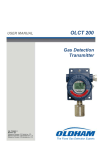
16
Gas Sensor
Measuring
Range
Sensor
Type
Display
Resolution
Default
Span Point
Default
Low Alarm
Default
High Alarm
Response
Time (T90)
1.10. Sensor Specifications
CO
0-1000
ppm
EC
1 ppm
100 ppm
35 ppm
70 ppm
<50 s
O2
0-25%
EC
0.1%
20.9%
19.5%
18.5%
<30 s
H2S
0-500
ppm
EC
1 ppm
25 ppm
10 ppm
20 ppm
<75 s
SO2
0-99.9
ppm
EC
0.1 ppm
5.0 ppm
2.0 ppm
4.0 ppm
<45 s
NO2
0-99.9
ppm
EC
0.1 ppm
5.0 ppm
1.0 ppm
2.0 ppm
<75 s
H2
0-1000
ppm
EC
1 ppm
100 ppm
50 ppm
100 ppm
<180 s
PH3
0-5 ppm
EC
0.01 ppm
1.00 ppm
0.30 ppm
0.60 ppm
<60 s
CH4
0-100%
LEL
CAT
1%
25% LEL
10% LEL
20% LEL
<45 s
CO2
0-5%
IR
0.1%
2.5%
1.5%
2.5%
<50 s
CH4
0-100%
LEL
IR
1%
25% LEL
10% LEL
20% LEL
<60 s
C3H8
0-100%
LEL
IR
1%
25% LEL
10% LEL
20% LEL
<60 s
NH3
0-500
ppm
EC
1 ppm
25 ppm
25 ppm
50 ppm
<75 s
P/N: 5600-9001 Rev 2
GDX-350 Sensor Transmitter
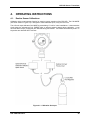
2.
INSTALLATION INSTRUCTIONS
2.1.
Sensor Location
Factors such as air movement, gas density in relation to air, emission sources and environmental
variables affect correct sensor location. Air movement by fans, prevailing winds and convection should
be carefully evaluated to determine if a leak is more likely to raise gas levels in certain areas within the
facility. Vapor density of a gas determines if it will rise or fall in air when there are no significant currents.
Lighter than air gases should have the monitors mounted 12-18 inches (30-45 centimeters) above the
potential gas leak and heavier than air gases should be the same distance below the point of leakage.
Even though the GDX-350 is designed for rugged service, sensors should be protected from water, snow,
shock, vibration, and dirt.
2.2.
Mounting the Enclosure
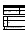
2.2.1 Stand-alone and Wired Networks
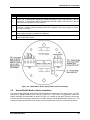
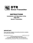
The GDX-350 standard enclosure is a cast aluminum explosion-proof (NEMA 7) enclosure as shown in
Figure 2-1.
Figure 2-1: GDX-350 Explosion-Proof Housing
Modular design simplifies the installation of the GDX-350. A top Display Assembly is mounted with
captive thumbscrews and is easily removed to access field-wiring terminals. An optional Alarms/Modbus
board (P/N 5600-0007) mounts piggyback to the back of the Display Assembly. The enclosure is
equipped with two threaded, 3/4 inch NPT conduit fitting outlet and pre-drilled mounting flanges.
WARNING: Qualified personnel should perform the installation according to applicable
electrical codes, regulations and safety standards. Insure that correct cabling and seal
fitting practices are implemented. Install the GDX-350 to a wall or bracket using the
predrilled mounting flanges with I.D. 0.25 on 5.5 inch centers (Figure 2-1). If conduit is
rigid and able to support the weight of the GDX-350, the mounting bolts may be omitted.
WARNING: The sensor should never be installed pointing upwards.
P/N: 5600-9001 Rev 2
17
GDX-350 Sensor Transmitter
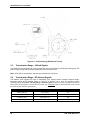
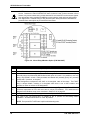
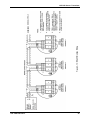
Figure 2-2: Outline Drawing (Stand-alone and Wired Version)
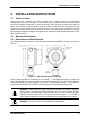
2.2.2 RF Wireless Networks
The standard enclosure for the RF version of the GDX-350 is a cast aluminum explosion-proof (NEMA 7)
enclosure as shown in Figure 2-3. Modular design simplifies the installation. The RF antenna should
typically be mounted with “line of site” access to the controller’s base station antenna. If a good “line of
site” angle is not possible the GDX-350s will usually still function properly at ranges up to 1500 feet, but
obstructions should be kept to a minimum.
18
P/N: 5600-9001 Rev 2
GDX-350 Sensor Transmitter
WARNING: Qualified personnel should perform the installation according to applicable
electrical codes, regulations and safety standards. Ensure correct cabling and sealing
fitting practices are implemented. Install the GDX-350 to a wall or bracket using the
predrilled mounting flanges with I.D. 0.25 on 5.0 inch centers (Figure 2-3).
CAUTION: The sensor head (not shown in Figure 2-3) should never be installed pointing
upwards.
The RF enclosure is NRTL certified for Division 1 hazardous area installations for explosion-proof Class 1
Groups B,C,D (see Figure 2-3). The RF version of the GDX-350 is designed to meet ISA 92.0.01 Part 1
for Toxic Monitors. The standard RF antenna fitting has an RP-SMA connector and is suitable for Division
2 classified areas. An optional antenna is also available for Division 1 classified areas. Figure 2-4 shows
both antenna styles.
Figure 2-3: GDX-350 (RF Version)
with Explosion Proof Housing
Figure 2-4: Local Antennas (900MHZ Shown)
Bacharach offers a square aluminum plate, with a magnet on each corner, to bolt to the back of the GDX-350’s
instrument enclosure. The Magnetic Mount securely attaches the assembly to solid steel structure that is at least 6
inches wide.
P/N: 5600-9001 Rev 2
19
GDX-350 Sensor Transmitter
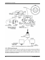
Figure 2-5: Outline Drawing (RF Network Version)
2.3.
Transmission Range: 4-20mA Signals
The distance 4-20 mA signals can travel is dependent upon several factors including the cable gauge, DC
power supply voltage level and input impedance of the receiving device.
Note: GDX-350 Controllers have 4-20 mA input resistance of 100 ohms.
2.4.
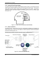
Transmission Range: RF Antenna Signals
The distance radio signals can travel is dependent upon several factors including antenna design,
transmitter power and Freespace losses. In order for a wireless link to work, the available system
operating margin (TX power - RX Sensitivity + Antenna gains) must exceed the Freespace loss and all
other losses in the system. For best RF line-of-site, the combined height of both antennas must exceed
the Fresnel zone diameter (see below).
Distance Between Antennas
Fresnel Zone Diameter
Freespace Loss (dB)
1000 ft (300 m)
16 ft (4.9 m)
81
1 Mile (1.6 km)
32 ft (9.7 m)
96
5 miles (8 km)
68 ft (20.7 m)
110
10 miles (16 km)
95 ft (29 m)
116
20
P/N: 5600-9001 Rev 2
GDX-350 Sensor Transmitter
Example:
The RF radio modem has the following parameters:
•
•
•
Maximum RF TX power setting = 30 dBm (1 Watt)
RF RX sensitivity = -100 dBm (this is a constant)
Antenna gain (standard equipped dipole) = 2.1dBi x 2 = 4.2dBi
So the system operating margin is:30 - (-100) + 4.2 = 134.2 dBm
This is enough to transmit 10 miles if freespace was the only loss in the system. For this to be the case,
the antennas must be mounted with a combined height greater than 95 ft above all obstructions (including
the ground) to keep the Fresnel zone clear. In practice however, there are many losses in the system
besides just freespace and it is recommended there be at least 20dB extra system operating margin.
RF “Rules of Thumb”:
• Doubling the range with good RF “Line of Site” (LOS) requires an increase of 6 dB.
• Doubling the range without good RF LOS requires an increase of 12 dB.
2.5.
Antenna Selection and Location
A site survey using an RF spectrum analyzer and test radios is highly recommended.
The location of the antenna is very important. Ensure the area surrounding the proposed location is clear
of objects such as other antennas, trees or power lines which may affect the antenna’s performance and
efficiency. It is also vital that you ensure the support structure and mounting arrangement is adequate to
support the antenna under all anticipated environmental conditions. The choice of appropriate mounting
hardware is also important for both minimizing corrosion and maintaining site inter-modulation
performance.
Most installations utilize locally mounted dipole antennas as shown in Figure 2-6. An option is available
for a 6 foot riser to increase the height of the antenna 6 feet above the GDX-350. Extreme cases may
require special order of directional antennas mounted in such a way to allow aiming towards the base
station antenna. Minimize obstructions between the GDX-350 and the base station antenna.
Figure 2-6: Local Antennas (900MHZ Shown)
P/N: 5600-9001 Rev 2
21
GDX-350 Sensor Transmitter
2.6.
Water Proofing Antenna Connection
Waterproof all outdoor coax connectors using a three layer sealing process of initial layer of adhesive
PVC tape, followed by a second layer of self-vulcanizing weatherproofing tape such as 3M 23, with a final
layer of adhesive PVC tape (see Figure 2-7).
Figure 2-7: Water Proofing Antenna Connections
2.7.
System Grounding
Direct grounding of the GDX-350 enclosure via a good electrical connection to a well designed grounding
system is essential. This will protect your system, reduce the damage that can occur during lightning
strikes and reduce noise.
2.8.
3-Wire 4-20 mA Mode Installation
WARNING: GDX-350s equipped with the I/O Power Supply board (P/N 5600-0006) only
operate as 3 or 4-wire 4-20 mA transmitters and are not compatible with 2-wire intrinsicallysafe installations. Such units should not be combined with IS Sensor Heads without flame
arrestors unless the area is classified as non-hazardous.
GDX-350s equipped with the I/O Power Supply (P/N 5600-0006) and Alarms/Modbus option (P/N 56000007) are NRTL certified as suitable for Div 1 and 2 Groups B, C, and D explosion proof installations with
the IS Sensor Head or with any sensor head with an equivalent CSA certification.
3-wire sourcing transmitters require an additional dedicated 24 VDC wire. The 4-20 mA loop current is
then delivered, or sourced, from the transmitter output and the receiver device must not provide 24 VDC
from its input terminal. When the GDX-350 is equipped with the bottom I/O Power Supply board (P/N
5600-0006) shown in Figure 2-8, the 2-wire 4-20 mA output is disabled and one of the boards’ 3-wire
outputs must be used. TB2 terminal 2 is for ECHEM toxic/oxygen 3-wire 4-20 mA output signals while the
TB2 terminal 3 is for LEL 3-wire 4-20 mA output signals.
22
P/N: 5600-9001 Rev 2
GDX-350 Sensor Transmitter
STEP
3-WIRE 4-20 mA MODE INSTALLATION
1.
Unscrew the cover on the GDX-350 explosion-proof enclosure.
2.
Loosen the 2 thumbscrews holding the display assembly in place and remove it (refer to
Figure 2-8). A small ribbon cable is attached with sufficient length to allow access to the I/O
PCB mounted in the bottom of the enclosure.
3.
Power and signal connections are to TB2 where 24 VDC, Signal and Common wires must be
connected. A blocking diode protects the GDX-350 if polarity of the power supply is reversed,
but it will not operate.
4.
Reassemble the GDX-350. Follow the procedures and recommendations in the receiver and
power supply manuals to complete the installation.
5.
Be sure the GDX-350 enclosure and conduit are properly grounded. Apply power and observe
that the GDX-350 functions.
Figure 2-8: 5600-0006 I/O Power Supply/3-Wire 4-20 mA Assembly
2.9.
Alarms/RS-485 Modbus Option Installation
The optional Alarms/RS-485 Modbus board (P/N 5600-0007) supplies two level alarm relays: a FAULT
relay and an RS-485 Modbus RTU slave port (Figure 2-9). This board is “piggybacked” behind the
Display Assembly (P/N 5600-0005) as shown in Figure 2-8. Addition of this option requires 3-wire mode,
4-20 mA operation and thereby requires the I/O Power Supply board (P/N 5600-0006) (Figure 2-8). This
is because relays and RS-485 circuits require much more power than 2-wire 4-20 mA loops can deliver.
P/N: 5600-9001 Rev 2
23
GDX-350 Sensor Transmitter
CAUTION: Alarm relays have dry contacts and power must be supplied from an external
source. Contacts are rated for RESISTIVE loads. Inductive loads, such as contactor coils or
motors, may cause contact arcing, which shortens life and emits RFI into the sensor signals.
Use appropriate arcing snubbers and MOVs across inductive loads and keep wiring away
from signal wires. External wiring to TB3 (Remote Alarm Reset) should be shielded and
protected from noise spikes to prevent false Alarm Reset.
Figure 2-9: Alarm Relays/Modbus Option (P/N 5600-0007)
STEP
Alarms/RS-485 Modbus Option Installation
1.
Unscrew the cover on the GDX-350 explosion-proof enclosure.
2.
Loosen the two thumbscrews holding the display assembly in place and remove.
3.
A small ribbon cable is attached with sufficient length to access the back of the Display
assembly where the Alarms/RS-485 Modbus board option is located. It is possible to use only
relays, only RS-485, or both. Relay terminals are labeled NO (normally open), NC (normally
closed) and C (common, or the pole).
These designators correspond to the shelf, or de-energized, state of the relays. The FAULT
relay is always failsafe, meaning it is energized when there is not a fault condition and
therefore its action is reverse of the designators.
4.
RS-485 Modbus networks should be wired as shown in Figure 2-10. Each GDX-350
connected represents an RTU and must have a unique RTU address. RTU addresses are
assigned in the Modbus setup menu described in Section 5.14 on page 44.
5.
Cabling must be a “daisy chain” as opposed to a “star” pattern for reliable operation.
6.
The “end of line” unit should have J1 installed in the ‘A’ position for terminating resistor
installation. All others should have J1 in the ‘B’ position.
NOTE: Front panel Rx/Tx LEDs are helpful troubleshooting tools.
24
P/N: 5600-9001 Rev 2
Figure 2-10: RS-485 Modbus Wiring
GDX-350 Sensor Transmitter
P/N: 5600-9001 Rev 2
25
GDX-350 Sensor Transmitter
2.10. Isolated 4-20 mA Output Option
The optional Isolated 4-20 mA option (P/N 5600-0009) as shown in Figure 2-11 provides dual 4-20 mA
outputs that are electrically isolated from sensor inputs and the 24 VDC power source. Each 4-20 mA
output shares the same common terminal and are not isolated from one another. This board is
“piggybacked” behind the Display Assembly (P/N 5600-0005) as seen in Figure 2-2. Addition of this
option requires 4-wire mode 4-20 mA operation and thereby requires the use of an I/O Power Supply
board (Figure 2-8).
Figure 2-11: Isolated 4-20 mA Output Option (P/N 5600-0009)
2.11. Sensor Installation
The GDX-350 Smart Sensor interface uses proven electrochemical technology for toxic/oxygen and
catalytic bead for LEL. In addition, a tiny memory IC is incorporated into GDX-350 factory supplied Smart
sensors allowing them to contain the entire database of GDX-350 parameters onboard the replaceable
Smart Sensor assembly (Figure 2-12).
Electrochemical and catalytic bead smart sensors both plug into the Smart Sensor Head that connects to
GDX-350 electronics with its 8-conductor Smart Sensor Interface cable (Figure 2-12).
Figure 2-12: Smart Sensor Head Assembly
26
P/N: 5600-9001 Rev 2
GDX-350 Sensor Transmitter
CAUTION: Smart sensor heads with electrochemical toxic/oxygen sensors must connect to
S1 located on the back of the Display Assembly (P/N 5600-0005) as seen in Figure 2-2.
Smart sensor heads with catalytic bead combustible sensors must connect to S1 located on
the optional I/O PCB assembly (Figure 2-8).
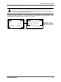
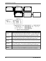
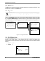
Smart Sensors are automatically recognized by the GDX-350. The Smart Sensor identification screen in
Figure 2-13 is shown after power-up, upon installation of a new smart sensor or by viewing INPUT type in
the SENSOR SETTINGS/INFO menu in Section 5.6 on page 39.
S MA R T
Ty pe:
Sp a n :
Zer o:
S N:
B o r n On :
Last
Ca l :
A NY k e y
S E N S OR
Ca t - B e a d
10 0
0
xxxxxx
0 1/ 2 8 / 0 4
04/ 05/ 04
t o Ex i t
E R R OR
C OD E
01
Incor r ect
Se n s o r
i nst al l ed. Inst al l
cor r ect
sensor
or
u p d a t e t r a n s mi t t e r .
S E E MA N U A L
E DI T k e y t o u p d a t e .
An y o t h e r
t o abor t .
If installed sensor
type does not match
transmitter database
Figure 2-13: Smart Sensor Info/ERROR Screens
P/N: 5600-9001 Rev 2
27
GDX-350 Sensor Transmitter
3.
INITIAL START-UP
3.1.
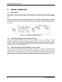
Model Name
When power is applied to the GDX-350 it will briefly show a 10-digit ASCII model and company name
during start-up. The name can be edited in the Transmitter Configuration menu by editing the Model
field.
Figure 3-1 shows how to access the menu for setting the 10-digit ASCII model name which is displayed
briefly after power is applied to the GDX-350 (RF shown). To access from any data display, press and
hold the NEXT key for 5-seconds until the screen appears requesting a special key sequence (4-UP
keystrokes).
Figure 3-1: Transmitter Configuration Menu
3.2.
Initial Toxic/Oxygen Sensor Monitor Start-Up
GDX-350 Toxic/Oxygen Monitors, which are factory equipped with a local Simple or Smart
electrochemical sensor, rarely require adjustments (other than routine calibrations) to provide accurate
readings. However, after installation the following check should be performed to ensure proper operation.
In addition, alarm levels, Measurement Name ASCII fields and other variables may require attention by
users in order to best serve their application.
3.3.
Initial Toxic/Oxygen Sensor Monitor “Span” Check
Prior to the initial Routine Sensor Calibration described in Section 4.1 on page 29, a coarse SPAN gas
reading verification (or bump test) should be performed after installation. Apply an upscale gas value of
at least 25% of full scale to the sensor. For example, if 0-100 ppm H2S is the measurement range, apply
at least 25 ppm, but not more than 100 ppm. Remember that this is only a coarse check and precision
calibrations are performed in Routine Sensor Calibrations described in the following Section 4.1.
28
P/N: 5600-9001 Rev 2
GDX-350 Sensor Transmitter
4.
OPERATING INSTRUCTIONS
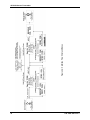
4.1.
Routine Sensor Calibrations
Calibration is the most important function for ensuring correct operation of the GDX-350. The CAL MODE
(flow chart shown in Figure 4-2) is designed to make calibration quick, easy and error free.
The 4-20 mA output indicates CAL MODE by transmitting 1.5 mA for 3-wire installations. It then transmits
4 mA during the subsequent CAL PURGE delay to prevent external alarms during calibration. Local
GDX-350 alarm relays (if equipped) are inhibited during CAL MODE. CAL MODE automatically exits if no
keystrokes are detected after 5 minutes.
Figure 4-1: Calibration Gas Input
P/N: 5600-9001 Rev 2
29
GDX-350 Sensor Transmitter
Follow these GDX-350 calibration guidelines:
Calibration accuracy is only as good as the calibration gas accuracy. Bacharach, Inc.
recommends calibration gases with NIST (National Institute of Standards and Technology)
traceable accuracy to increase the validity of the calibration.
Do not use a gas cylinder beyond its expiration date.
Calibrate a new sensor before use.
Allow the sensor to stabilize before starting calibration (approximately 5 minutes).
Calibrate on a regular basis. (Bacharach, Inc. recommends once every 3 months, depending on
use and sensor exposure to poisons and contaminants.)
Calibrate only in a clean atmosphere, which is free of background gas.
•
•
•
•
•
•
Use the following step-by-step procedure to perform ZERO and SPAN calibrations.
The flow chart in Figure 4-2 illustrates the following procedure. UP, CAL, NEXT and EDIT labels indicate
keystrokes using the magnetic wand. The CAL MODE information screen (located on the top of the
chart) is available for advanced users to see Offset/Gain calibration constants and live analog to digital
converter (A/D) counts. Span Gas calibration values may also be edited from this screen. Holding the
UP key for 5 seconds during CAL MODE displays this screen.
Calibration history records are logged and may be viewed in the Sensor Information menu (see Section
5.6 on page 39).
Step
ZERO and SPAN Calibrations
1.
To enter the CAL MODE from either of the data displays, press the DOWN/CAL key and within 5
seconds press the EDIT key.
2.
Using the Cal-Cup, apply a clean ZERO gas or be sure there is no background target gas in the
monitored area. After the reading is stable, (approximately 1 minute) press the EDIT key to
perform a ZERO calibration.
3.
If the ZERO calibration is successful, press the NEXT key to proceed to the SPAN check. Once
ZERO CAL is successful, the unit automatically proceeds to SPAN CHECK. If NEXT is pressed
now, it will exit the CAL routine. However, if NEXT is pressed when first in CAL, it will skip
ZERO CAL and go to SPAN CHECK.
4.
Apply the correct SPAN gas at 0.5 liters/min. After the reading is stable (approximately 1
minute), press the EDIT key to perform a SPAN calibration.
WARNING: The SPAN gas used must match the value specified since this is
what the GDX-350 will indicate after a successful SPAN calibration. The Cal Span
Value may be edited if it becomes necessary to apply a different gas concentration
(see Cal Span Value in Section 5.3 on page 35).
30
5.
Once the SPAN calibration is successful, the display flashes “REMOVE CAL GAS” and starts
the CAL PURGE delay.
6.
CAL MODE will be complete after the end of the CAL PURGE delay.
P/N: 5600-9001 Rev 2
GDX-350 Sensor Transmitter
4.2.
Alarm Operation
GDX-350s have front panel LED indicators for Alarm 1, Alarm 2 and Alarm 3. An optional Relay/Modbus
board (P/N 5600-0007) adds K1, K2, and K3 relays for these alarms.
CAUTION: GDX-350 Alarm LED indicators function even without the presence of the 56000007 Relay option. With 3-Wire 4-20 mA operation, alarm LEDs flash when new and
becomes steady after the operator selects ACKNOWLEDGE by pressing the UP/RESET
key.
4.3.
Alarm 3 – Understanding Fault/Level Operation
The “A3” alarm is typically dedicated to FAULT conditions indicating sensor failures or “out of
measurement range” conditions. However, some applications require a third level alarm. The A3 menu is
identical to A1 and A2 and may be set to trip at an upscale level value. A3 will also trip with missing or
failed sensors regardless of the level value.
CAUTION: Missing or failed sensors always trip Alarm 3 and relay K3 (if equipped). This is
true even with A3 configured as a level alarm and it must be realized that A3 level alarm
events might be caused by the monitored level or by a missing or failed sensor.
P/N: 5600-9001 Rev 2
31
Figure 4-2: Cal-Mode Flow Chart and Menus
GDX-350 Sensor Transmitter
32
P/N: 5600-9001 Rev 2
GDX-350 Sensor Transmitter
5.
SETUP MENU CONFIGURATION
5.1.
Menus Database Configuration
All GDX-350 configuration variables are stored in its menu database. Many menu items will contain
default values from the factory and require changes to better match a user’s particular application.
GDX-350 menus may be configured from the magnetic keypad.
The GDX-350’s configuration menus are shown below.
Figure 5-1: Configuration Menu Tree
P/N: 5600-9001 Rev 2
33
GDX-350 Sensor Transmitter
Figure 5-2: Configuration Menu Tree (RF Model)
34
P/N: 5600-9001 Rev 2
GDX-350 Sensor Transmitter
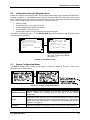
5.2.
Configuration Using the Magnetic Wand
Passing the magnetic wand past the EDIT key from either data display screen displays SETUP PAGE 1
as shown in Figure 5-3. The UP/DOWN keys maneuver the pointer while EDIT enters sub-levels of menu
items. All SETUP menu items have at least one page of sub-menus. Items with sub-menus are indicated
by the > symbol (right arrow) at the end of each line. Edit menu items by:
•
•
•
•
•
pointing to them
pressing the EDIT key to display the cursor
pressing UP/DOWN to change that character
pressing NEXT to move the cursor
pressing EDIT again to load the new item and remove the cursor.
Press NEXT to exit the sub-menu. To view SETUP PAGE 2, press the DOWN key with the pointer aimed
at the bottom item on PAGE 1.
L E L I NP UT 1
S y s t e m Co n f i g .
Al a r m Se t t i n g s
Se n s o r
I n f o r ma t i o n
Cl o c k / De l a y s
Di a g n o s t i c s
HE L P
(Instructions)
>
>
>
>
>
>
L EL
EDIT
L CD
Mo d b
Se c u
Tec h
Se n s
Fi
I NP UT
2
Co n t r a s t
Ad j .
u s RS 4 8 5 P o r t
r i t y
n i c i a n s ON L Y
or
T e mp
r mw a r e R e v .
>
>
>
>
>
“Sensor Temp” menu only present
with “Arctic” smart sensor installed.
See section 7.1.
Figure 5-3: Setup Menu Entry
5.3.
System Configuration Menus
The System Config. group consists of two pages of menus as shown in Figure 5-4.
description follows in this section.
Each item’s
Figure 5-4: System Configuration Menus
Menu Item
Description
Measurement Name
May be edited to contain virtually any 16-character ASCII field. It is typically
used to describe the monitored point by user tag # or other familiar
terminology.
Eunits
Engineering Units - May have up to a 10 character ASCII field. Many common
gases have pre-configured Eunits based upon the sensor type. Each may be
edited in this menu as described in Configuration Using the Magnetic Wand in
Section 5.2 on page 35.
Zero (0%)
Defines the reading to be displayed when 4 mA (0%) is the GDX-350 output.
P/N: 5600-9001 Rev 2
35
GDX-350 Sensor Transmitter
Menu Item
Description
Span (100%)
Defines the reading to be displayed when 20 mA (100%) is the GDX-350
output. The highest reading allowed is 9999. Included is a negative polarity
sign and one decimal point. Polarity is only indicated for negative readings.
Decimal Points
Sets the resolution of the LCD readings and may be for 0, 1 or 2. Example:
ZERO readings for 0, 1, and 2 DPs respectively are 0, 0.0, and 0.00.
Cal Span Value
Sets which upscale value must be applied when performing Span calibrations.
Readout Deadband
Allows for forcing of low values to continue to read zero. This is useful when
there are small amounts of background gases that cause fluctuating readouts
above zero. The highest amount of deadband allowed is 5%. The 4-20 mA
output is not affected by this menu item.
Track Negative
(Default set to NO) Causes negative values to read the Zero (0%) value in
data displays. The CAL MODE readout displays negative values regardless of
this setting and negative values below the Fault set point will still cause the
Fault alarm to trip. The 4-20 mA output always locks at 4 mA when the
reading is negative.
Linearization Data
Allows nonlinear signals to be linearized by entering the correct curve into the
GDX-350 (Figure 5-5). If Linearize is set for NO, the CURVE POINTS menu
data is not used and no linearization is applied. When YES, the CURVE
POINT entries are used and a straight-line approximation is calculated
between each of the 9 entries. 0% input always provides 0% output and 100%
input always provides 100% output. To prevent accidental data entry a special
keystroke sequence of 4 consecutive UP keys is required to enter this menu.
En t e r
Ke y Se q u e n c e
t o a c c e s s me n u .
* * * *
NE X T k e y t o E x i t .
Se e
Ma n u a l
PRESS
UP KEY
4-TIMES
CURV E
P OI N T S
Li near i ze ?
NO
Da t a P o i n t
1
% Input
10 . 0 0
% Ou t p u t
10 . 0 0
Figure 5-5: Linearization Menu
Menu Item
Description
Backup Config.
Allows users to store the entire, current GDX-350 menu database into nonvolatile memory for restoration later, in the case that incorrect values are
accidentally entered or uploaded.
Restore Config.
Restores the GDX-350 menu database to the values from the most recent
Backup Configuration. This menu item is only available if a smart sensor is not
installed. The special keystroke sequence of 4 consecutive UP keys is also
required to perform backup and restore operations.
Upload Sensor Data
Allows manual uploading of the entire smart sensor database to the GDX-350
from the smart sensor.
Cal Marker
Allows setting of the 4-20 mA output value during ZERO and SPAN
calibrations at a level to prevent alarm trips by calibration values. Three-wire
models may be set from 0 to 20 mA.
36
P/N: 5600-9001 Rev 2
GDX-350 Sensor Transmitter
Menu Item
Description
TX Sensor Life
(Default is set for YES) Causes the GDX-350 4-20 mA output to transmit a
sensor life value after successful calibrations during the CAL PURGE delay
(see Section 4.1 on page 29). Normal operation is such that the GDX-350
transmits 4 mA during the CAL PURGE delay. But with TX Sensor Life =
YES it transmits 4 mA for the first 10-seconds, then for 5-seconds transmits a
value between 4 mA and 5 mA, with 4 mA equal to 0% sensor life and 5 mA
equal to 100% sensor life (see Figure 5-6). The output then returns to 4 mA
for the remainder of the CAL PURGE delay. For example, if after a calibration
the sensor life is 75%, the GDX-350 transmits 4.75 mA during the 5-second
interval.
NOTE: TX Sensor Life should always be set for NO unless the 4-20 mA receiver is capable of
interpreting the sensor life signal. The Bacharach, Inc. GDX-1600 Controller is capable of this
function.
Figure 5-6: Transmit Sensor Life Timing Diagram
5.4.
Alarm Settings
The Alarm Settings page has the Alarm 1, 2, 3 Setups, Relays and Event Log submenus shown in
Figure 5-7. Alarm 1, Alarm 2 and Alarm 3/Fail menus are identical and therefore described only once in
this section.
IMPORTANT: Alarm functions and their associated LEDs are active without the
Relay/Modbus (P/N 5600-0007) option installed.
P/N: 5600-9001 Rev 2
37
GDX-350 Sensor Transmitter
Alarm 1, 2, 3 menus
are identical
A L A RM
Al a
Al a
Al a
Re l
Al a
r
r
r
a
r
m
m
m
ys
m
S E T T I N GS
1
2
3/ Fai l
Co n f i g .
Ev e n t
Log
A L A RM
>
>
>
>
>
x
E V E NT
RE L A Y
S E T UP
Se t
Po i n t
De a d - B a n d
ON D e l a y
OF F D e l a y
Low Tr i p
Lat chi ng
L OG
Di s p l a y E v e n t
Log
Cl e a r
Ev e n t
Log
C ON F I G
K1 Fa i l s a f e
NO
K2 Fa i l s a f e
NO
K 2 A c k n o wl e d g e NO
K 2 Re f r e s h
Of f
* K 3 a l wa y s F a i l s a f e *
20
1%
0s
0m
NO
NO
Edit
0
0
0
0
0
0
0
0
8
8
8
8
8
8
8
8
/
/
/
/
/
/
/
/
12
12
12
12
12
12
12
13
/
/
/
/
/
/
/
/
0
0
0
0
0
0
0
0
4
4
4
4
4
4
4
4
0 3 : 17
03:51
03:55
0 4 : 16
04:23
15 : 0 0
16 : 4 3
02:08
A1 I N
A2 I N
A CK
A 2 OU T
A 1O U T
A1 I N
A 1O U T
A3 I N
0 8 / 13 / 0 4
- - - E ND
0 2 : 18 A 3 OU T
OF L OG - - -
Down
Figure 5-7: Alarm Settings Menus
Menu Item
Description
Set Point
Enters the engineering unit value where the alarm trips. It may be negative and trip
when monitored values fall out of range in this direction. A3 has a default negative
5% of range Set Point with Low Trip set for YES. This makes it function as a
FAULT alarm and trip when the monitored value is more than 5% “out of range”.
Dead-Band
Has a minimum value of 1% and a maximum value of 10%. It is useful for
preventing alarm cycling of 0-100 ppm, if Dead-Band equals 5% and the set point is
20 ppm, after tripping at 20 ppm the value must drop below 15 ppm to reset.
ON Delay
Allows entering a maximum 10 second delay before this alarm becomes active.
This is useful for preventing nuisance alarms caused by brief spikes beyond the set
point.
OFF Delay
Allows entering a maximum 120 minute delay before clearing an alarm after the
alarm condition is gone. This is useful for continuing an alarm function, such as
operation of an exhaust fan, for a period of time after the alarm condition clears.
Low Trip
(Default set to YES) Causes the alarm to trip as the value falls below the set point.
Latching
(Default set to YES) Causes the alarm to remain active even after the condition is
gone and only reset when the UP/RESET key is pressed from a data display.
38
P/N: 5600-9001 Rev 2
GDX-350 Sensor Transmitter
5.5.
Relay Configuration (If Equipped)
Relay Config has the submenu shown in Figure 5-8. The optional relay PCB must be installed to access
this menu or a “HARDWARE NOT PRESENT” message appears.
RE L A Y
C ON F I G
K1 Fa i l s a f e
NO
K2 Fa i l s a f e
NO
K 2 A c k n o wl e d g e NO
K 2 Re f r e s h
Of f
* K 3 a l wa y s F a i l s a f e *
Figure 5-8: Relay Configuration Menu
Menu Item
Description
K1/K2 Failsafe
(Default set for YES) Means that the relay de-energizes during alarm and
energizes with no alarm. This is useful for signaling alarm when GDX-350
power is lost. K3 is a FAULT alarm and is always failsafe.
K2 Acknowledge
(Default set for YES) Means that the UP/RESET key (RESET key during either
data display) will set K2 to the normal state EVEN when an Alarm 2 condition
exists. This is useful for silencing an audible device, driven from K2, during the
alarm condition.
K2 Refresh
(Default set for ON) Causes an acknowledged Alarm 2 condition to reactivate
K2 if it continues beyond the designated Refresh interval (0-99 minutes). This
feature insures against forgotten alarms after an Acknowledge.
5.6.
Sensor Information
Sensor Information has the SENSOR SETUP/INFO menus shown in Figure 5-9.
S E N S OR
S E T T I N GS / I N F O
Inst al l
Se n
Re c a l l
Ca l
Input
Ty pe
Ne w S e n s o r
Re c e n t
Ca l
Se n s o r
sor
>
Hi s t o r y
>
>
S MA R T
0 1/ 2 8 / 0 4
04/ 05/ 04
Li f e
EDIT
I NS T A L L
An y o t h e r
t o Ex i t .
EDIT
key
C A L I B R A T I ON
Re c o r d 2 2
CA L Da t e :
U P / D O WN
NE X T t o
I NS T A L L
N E W S E N S OR
E DI T t o i n s t a l l
Ne w S e n s o r .
N E W S E N S OR
Hi s t o r i c a l
CA L d a t a
Wi l l
b e De l e t e d .
E DI T t o
NE X T t o
Ac c e p t
Ab o r t
DA T E S
of
22
04/ 05/ 04
t o scr ol l
EXI T .
S MA R T
Ty pe:
Sp a n :
Zer o:
S N:
B o r n On :
Last
Ca l :
A NY k e y
S E N S OR
Ca t - B e a d
10 0
0
xxxxxx
0 1/ 2 8 / 0 4
04/ 05/ 04
t o Ex i t
Figure 5-9: Sensor Information Menus
P/N: 5600-9001 Rev 2
39
GDX-350 Sensor Transmitter
Menu Item
Description
Install New Sensor
Should always be performed when a new simple sensor is installed. This
deletes historical CAL data and sets sensor life to 100% after initial calibration
of the new simple sensor. The GDX-350 Smart sensor interface will
automatically detect new smart sensors and this menu is therefore not available
with a smart sensor connected.
Recall Cal History
Recalls each successful calibration. These dates may be reviewed by scrolling
with the UP/DOWN keys.
Input Type
Indicates which type of input or sensor the GDX-350 is configured to accept and
is pre-configured at the factory. There are four Input Type possibilities
consisting of bridge, EC negative, EC positive, and 4-20 mA (all are Smart
Sensors). Smart Sensors upload sensor type and other data to the GDX-350
and may be viewed on the SMART SENSOR information screen.
New Sensor
Displays the date when a new sensor was last installed.
Recent Cal
Displays the most recent calibration date.
5.7.
Clock/Delay Setup
The GDX-350 is equipped with a Real Time Clock and Calendar Time and Date and must be set to
correctly match its location. They are set at the factory in a 24 hour format but may require adjustment to
match the location’s time and date after shipment. Follow the procedure in Configuration Using the
Magnetic Wand in Section 5.2 on page 35.
Warm Up and Cal Purge time delays are also available to prevent unwanted alarm trips. Figure 5-10
shows the menu for these items.
C L OC K / D E L A Y
S E T UP
T i me
12 : 3 5 : 4 2
Da t e
04/ 22/ 04
Wa r m U p S e c
12 0
Ca l P u r g e S e c
10 0
Figure 5-10: Clock and Calendar/Delay Timer Menu
5.8.
Communications Setup (RF Communications)
The Communications menu provides access to RADIO SETUP menus described below. Hop Channel
and System ID settings must match these settings in the Server. Remote ID must be unique to each
GDX-350. Items tagged with an asterisk affect power consumption and may have significant affects upon
battery life.
Figure 5-11: Radio Setup Menu
40
P/N: 5600-9001 Rev 2
GDX-350 Sensor Transmitter
Menu Item
Hop Channel
Description
May be set from 1-32 and assigns the pseudo-random radio frequency hopping
pattern. A transceiver will not go In Range of or communicate with a transceiver
operating on a different Hop Channel. Different hop channels can be used to
prevent radios in one network from listening to transmissions of another.
Installations having more than one Server network should also have different hop
channels for each network.
2.4GHZ variation: Hop channels on 2.4 GHZ models may be set between 0 and
39. Hop channels 0-19 includes EU “low band” frequencies 2406 – 2435MHZ.
Hop channels 20-39 includes EU “high band” frequencies 2444 – 2472MHZ.
IMPORTANT!! EXPLORE WHAT FREQUENCIES ARE APPROPRIATE FOR THE
FINAL LOCATION OF ANY WIRELESS SYSTEM.
Remote ID
May be set from 1-255 and acts as the “RTU” address for this particular GDX-350.
Controller channels receiving this monitor’s data must also be configured with this
matching Remote ID address.
System ID
May be set from 1-255 and is similar to a password character or network number
and makes network eavesdropping more difficult. A transceiver will not go In Range
of or communicate with a transceiver operating on a different System ID.
TX Multiples
Allows up to 5 consecutive repeats of EVERY transmission. The default setting of 1
should only be increased if there is no other way to improve communications
success. Power consumption increases with radio transmissions and battery life will
be affected by raising the TX Multiples setting.
*RF
Handshaking
Affects the way RF transmissions are made by the GDX-350. This menu may be set
for OFF (default) or ON. OFF requires no acknowledge from the receiving server.
ON should be used only when transmitting to a single receiving server (such as a
GDA-400 or GDA-1600 Controller). Since ON creates an “acknowledge” hand
shake returned from the receiver, only one receiver is allowed to avoid data
collisions of the “acknowledge” signal. If an “acknowledge” is not received by the
GDX-350 it transmits repeatedly up to 16 times. RF HANDSHAKING = OFF may be
used for any application but is required when transmitting to a Server and other
receiver Client radios. RF HANDSHAKING = ON always transmits the packet 4
times and does not require any “acknowledge” returned by the receivers.
TX Power
(900MHZ models only) May be set for 10 mW, 200mW, 400mW and 1 watt. Since
GDX-350s are battery powered the TX Power setting should be as low as possible
to sustain reliable communication. The maximum TX Power setting is 30db (1 watt)
and each time TX power is reduced by half, antenna transmit power is reduced by
3dB.
2.4GHZ variation: The TX Power menu is not available in 2.4GHZ models and
is fixed at 50mW.
TX Verbose
Wakeup Time
Unavailable for firmware revisions 3.09 and earlier.
Menu is new to firmware revision 3.09 and determines how often the radio is
activated WHEN THERE IS NOT AN A1 or A2 LEVEL ALARM. The default value is
300 seconds (5 minutes) but this may be reduced to as low as 6 seconds. Intervals
are rounded up to the nearest 6 seconds regardless of the menu entry (example: 50
second entry transmits every 54 seconds).
IMPORTANT: More frequent RF transmissions deplete the battery
faster!
P/N: 5600-9001 Rev 2
41
GDX-350 Sensor Transmitter
Menu Item
Description
Radio Status
Opens another screen that shows if the RF GDX-350 is In Range of the Server and
what the battery voltage is. Battery voltage is also displayed on the “EC INPUT PG.
2” screen.
* TX Multiples
RF
Handshaking
Menu settings are available to improve communications reliability by increasing the
quantity and power of wireless transmissions.
IMPORTANT: Ensure proper selection and location of antennas
before increasing TX Multiples and TX Power settings! Battery life
will be reduced by increasing these settings. Proper selection and
location of antennas contributes much more to successful
communications, without sacrificing battery life, than these settings.
TX Power
5.9.
Base Stations
Figure 5-12 shows correct settings for the GDA-1600 base station’s “Data From” menu to receive data
from RF GDX-350s. Each controller channel’s Remote ID must match the GDX-350’s Remote ID setting
in order for its VALUE to appear on the desired controller channel. The GDX-350 counts value equals 75
counts, or -15.6%, during CAL MODE. Enabling the GDX-350’s “INPUT MARKER” menu as shown on the
right menu in Figure 5-12 causes the GDA-1600 controller to indicate IN CAL when the GDX-350 has its
CAL MODE activated.
Input Req set for VALUE means this GDA-1600 channel reads the GDX-350’s monitored gas value. If the
Input Req menu is set for BATT this GDA-1600 channel reads the battery voltage from the GDX-350 with
the same Remote ID. To properly display battery voltage, the GDA-1600’s engineering unit range should
be 0-5.00 VDC. Even if this channel reads VALUE from the GDX-350, the battery voltage is displayed at
the bottom of this GDA-1600 menu as shown in Figure 5-12.
Figure 5-12: GDA-1600 Base Station “Data From” Menu
FIGURES 5-13 and 5-14 show correct settings for a GDA-400 base station to receive data from RF
GDX-350s.
Figure 5-13
42
P/N: 5600-9001 Rev 2
GDX-350 Sensor Transmitter
GDA-400 base stations must have their Communications menus set for Wireless Receiver mode as
shown in Figure 5-12. In Receiver mode the GDA-400 may have 1-4 channels configured to receive input
data from 1-4 GDX-350 sensor transmitters.
Channel input type is configured in the ANALOG SETUP menu located within the Input/Output Setup
menus as shown in Figure 5-13. GDX-350s transmit 200 counts for 0% and 1000 counts for 100% full
scale readings so Input Min/Max menu values should be 200 & 1000. The Rmt. Xmitter ID menu entry
must match the Remote Id address setting in the GDX-350 providing data to this GDA-400 channel.
Voltage level of the 3.6 volt lithium battery in this GDX-350 is also displayed on this screen. The most
recent A/D Counts value is displayed at bottom of the screen.
Figure 5-14
5.10. System Security
The SYSTEM SECURITY menu in Figure 5-14 offers two levels of protection. A LOW level allows CAL
MODE sensor calibrations but requires the 4-digit Pass Code prior to altering menus. HIGH level locks
the entire menu database and CAL Mode until the correct Pass Code is entered. LOW and HIGH
security levels always allow viewing of configuration menus but they may not be changed. Contact Name
is a 12 character ASCII field available for displaying a phone # or name of personal who know the Pass
Code. Lost Pass Codes may be recovered by entering the locked security menu and holding the UP key
for 5 seconds. The 4-digit code appears near the bottom of the screen.
Figure 5-15: System Security Menu
5.11. LCD Contrast Adjustment
LCD Contrast Adj. May be set for optimum viewing using the menu shown in Figure 5-16.
C ON T R A S T
U P / D O WN
NE X T
t o
change
t o
EXI T
Figure 5-16: LCD Contrast Adjust Menu
P/N: 5600-9001 Rev 2
43
GDX-350 Sensor Transmitter
5.12. HELP Screen
The HELP screen contains several pages of information describing how to operate the GDX-350. This is
the bottom menu on page 1 of the SETUP screen.
5.13. Diagnostics
IMPORTANT: Gas monitoring and alarm processing are not performed while using the
Diagnostics menus. Access requires a special key sequence of four consecutive UP
keystrokes.
There are two Diagnostics menus useful for driving outputs without exposing the sensor to the target
gas. The OUTPUT SIMULATION menu allows for setting of the 4-20 mA output to virtually any desired
value. This is useful for checking responses of devices receiving the GDX-350’s 4-20 mA output. The
ACTIVATE RELAYS menu allows for tripping of the alarm relays (if equipped) without tripping alarm setpoints with the target gas.
* * *
WA R N I N G
* * *
A l a r m p r o c e s s i n g wi l l
be hal t ed dur i ng
d i a g n o s t i c mo d e !
OU T P U T
D I A G N OS T I C S
Ou t p u t
S t i mu l a t i o n
Re l a y T e s t
EDIT
EDI T t o c o n t i n u e .
An y o t h e r
key t o exi t .
S T I MU L A T O R
Ou t p u t
E DI T
Ne x t
4.0
t o
t o
change.
exi t .
A CT I V AT E
Re l a y
Re l a y
Re l a y
mA
RE L A Y S
1
2
3
OF F
OF F
OF F
Figure 5-17: Diagnostics Menus
5.14. RS-485/Modbus Setup
The RS-485 MODBUS SETUP menu allows setting the RTU address (if RS-485 equipped) for each
GDX-350 on the RS-485 network. Each GDX-350 must have a different RTU address when
communicating on the same 2-wire cable. Baud rate, parity and stop bits are fixed at industry standard
values of:
•
•
•
Baud Rate:
Parity:
Stop Bits:
9600
None
1.
RS 4 8 5
MOD B U S
RT U A d d r e s s
B a u d Ra t e
Pa r i t y
St o p Bi t
S ET UP
1
9600
No n e
1
Figure 5-18: Modbus RS-485 Setup Menu
44
P/N: 5600-9001 Rev 2
GDX-350 Sensor Transmitter
5.15. Modbus Register and Function Code Summary
The following tables identify GDX-350 Modbus register locations and function codes. “Chan 1”
designations represent the EC channel while “Chan 2” represents the LEL/4-20 mA Input channel.
Read Only Discretes
VARIABLE
ALIAS
READ FUNCTION CODE
WRITE FUNCTION CODE
Chan 1 Alarm 1
2001
2
NA
Chan 1 Alarm 2
2002
2
NA
Chan 1 Fault
2003
2
NA
Chan 2 Alarm 1
2004
2
NA
Chan 2 Alarm 2
2005
2
NA
Chan 2 Fault
2006
2
NA
K1
2007
2
NA
K2
2008
2
NA
K3
2009
2
NA
Chan 1 Cal Mode
2010
2
NA
Chan 2 Cal Mode
2011
2
NA
ALIAS
READ FUNCTION CODE
WRITE FUNCTION CODE
12001
1
5
Read/Write Coils
VARIABLE
Alarm Ack/Reset
Note: After writing a TRUE to this register, it resets back to FALSE automatically.
Read Only Registers
VARIABLE
ALIAS
READ FUNCTION CODE
WRITE FUNCTION CODE
1
31001
4
NA
1
31002
4
NA
2
31003
4
NA
2
31004
4
NA
31005
4
NA
31006
4
NA
31007
4
NA
31008
4
NA
31009
4
NA
D2A Raw Chan 1
D2A Raw Chan 2
A2D Raw Chan 1
A2D Raw Chan 2
Chan 1 Status
3
Chan 2 Status
3
4
Alarm Status Word
Transmitter Status Word
1
2
Chan 1 Sensor Life
6
Chan 2 Sensor Life
6
5
31010
4
NA
Chan 1 Sensor Temperature
7
31011
4
NA
Chan 2 Sensor Temperature
7
31012
4
NA
Calibrated 10-bit value representing the D2A value of 0 to 1023 for -25 to 105 %FS (200=0% and 1000=100%).
IMPORTANT: Read registers 31001/31002 to create readings that match GDX-350 display values! These
should also be read by GDX-1600 Modbus masters.
10-bit value representing the A2D value of 0 to 1023 before calibration constants are applied.
P/N: 5600-9001 Rev 2
45
GDX-350 Sensor Transmitter
3
16-bit status words; bit assignment for each channel. See below.
ALARM1_BELOW
BIT0
ALARM2_BELOW
BIT1
ALARM3_BELOW
BIT2
ALARM1_LATCH
BIT3
ALARM2_LATCH
BIT4
ALARM3_LATCH
BIT5
ALARM3_ACTIVE
BIT6
CHANNEL_DISABLED
BIT7
CHANNEL_CAL
BIT8
CHANNEL_LINEARIZE
BIT9
FAULT_RELAY_LATCH
BIT10
DISPLAY_NEGATIVE
BIT11
TRANSMIT SENSOR LIFE ENABLED
BIT12
4
16-bit status word; bit assignment for system status. See below.
CH1_ALM1
BIT0
CH1_ALM2
BIT1
CH1_FAULT
BIT2
CH2_ALAM1
BIT4
CH2_ALM2
BIT5
CH2_FAULT
BIT6
K1_STATUS
BIT8
K2_STATUS
BIT9
K3_STATUS
BIT10
5
16-bit status word; bit assignment for system status. See below.
CHAN_1_ACTIVE
BIT0
CHAN_2_ACTIVE
BIT1
SECURE_LEVEL
BIT2
MARKER Tx LED
BIT3
K1_FAILSAFE
BIT12
K2_FAILSAFE
BIT13
K2_ACK
BIT14
LOCK
BIT15
6
7
16-bit signed integer ranging from –1 to 100 where -1 indicates Cal Required.
16-bit integer ranging from 1 to 4095 scaled for –55 to +125 degrees C.
Memory Floating Point
VARIABLE
ALIAS
READ FUNCTION CODE
WRITE FUNCTION CODE
FP Value Chan 1
33001
4
NA
FP Value Chan 2
33002
4
NA
NOTE: Returned as 15-bit plus sign 2’s complement with ±5% over/underrange applied. Consider
over/underrange when scaling values to be displayed at the workstation. The following equation
may be used to determine a value for display.
Display Value = MODBUS Value [ (Span Value -Zero Value) 1.1] + {Zero Value - [(Span Value - Zero Value) .05]}
32767
46
P/N: 5600-9001 Rev 2
GDX-350 Sensor Transmitter
Memory ASCII Strings
VARIABLE
User Info Chan 1
1
User Info Chan 2
1
40401-40408
3
NA
3
NA
40417-40419
3
NA
2
40420-40422
3
NA
EUNITS Chan 1
3
40423-40427
3
NA
EUNITS Chan 2
3
40428-40432
3
NA
16 ASCII characters (2 per register) assigned to the unit identifier read as bytes.
6 ASCII characters (2 per register) reflecting the display readout.
10 ASCII characters (2 per register) assigned to the engineering units read as bytes.
Byte Variables
VARIABLE
ALIAS
READ FUNCTION CODE
WRITE FUNCTION CODE
1
40433
3
NA
1
40434
3
NA
PreAmp/Gain Ch1
PreAmp/Gain Ch2
2 bytes representing Pre Amp (HiByte) and PGA (LoByte) settings.
Firmware Version
2
1
Version
1
WRITE FUNCTION CODE
40409-40416
Chan 2 ASCII Reading
1
READ FUNCTION CODE
2
Chan 1 ASCII Reading
1
2
3
ALIAS
ALIAS
READ FUNCTION CODE
WRITE FUNCTION CODE
40435-40436
3
NA
4 ASCII characters (2 per register) reflecting the firmware version.
Memory Reals
NOTE: Real value represents float value without the decimal point such as 123.4 is returned as 1234.
Decimal divisor is returned as 1, 10, 100, or 1000 for decimal position of 1, 2, 3, or 4, where
123.4 would return the value 10.
VARIABLE
ALIAS
READ FUNCTION CODE
WRITE FUNCTION CODE
Chan 1 Cal Zero Real
41001
4
NA
Chan 1 Cal Zero Divisor
41002
4
NA
Chan 1 Cal Span Real
41003
4
NA
Chan 1 Cal Span Divisor
41004
4
NA
Chan 1 Zero Real
41005
4
NA
Chan 1 Zero Divisor
41006
4
NA
Chan 1 Span Real
41007
4
NA
Chan 1 Span Divisor
41008
4
NA
Chan 1 Fault Real
41009
4
NA
Chan 1 Fault Divisor
41010
4
NA
Chan 1 Alarm 1 Real
41011
4
NA
Chan 1 Alarm 1 Divisor
41012
4
NA
P/N: 5600-9001 Rev 2
47
GDX-350 Sensor Transmitter
VARIABLE
ALIAS
READ FUNCTION CODE
WRITE FUNCTION CODE
Chan 1 Alarm 2 Real
41013
4
NA
Chan 1 Alarm 2 Divisor
41014
4
NA
Chan 1 Alarm 3 Real
41015
4
NA
Chan 1 Alarm 3 Divisor
41016
4
NA
Chan 1 Manual Gain Real
41017
4
NA
Chan 1 Manual Gain Divisor
41018
4
NA
Chan 1 Manual Offset Real
41019
4
NA
Chan 1 Manual Offset Divisor
41020
4
NA
Chan 2 Cal Zero Real
41021
4
NA
Chan 2 Cal Zero Divisor
41022
4
NA
Chan 2 Cal Span Real
41023
4
NA
Chan 2 Cal Span Divisor
41024
4
NA
Chan 2 Zero Real
41025
4
NA
Chan 2 Zero Divisor
41026
4
NA
Chan 2 Span Real
41027
4
NA
Chan 2 Span Divisor
41028
4
NA
Chan 2 Fault Real
41029
4
NA
Chan 2 Fault Divisor
41030
4
NA
Chan 2 Alarm 1 Real
41031
4
NA
Chan 2 Alarm 1 Divisor
41032
4
NA
Chan 2 Alarm 2 Real
41033
4
NA
Chan 2 Alarm 2 Divisor
41034
4
NA
Chan 2 Alarm 3 Real
41035
4
NA
Chan 2 Alarm 3 Divisor
41036
4
NA
Chan 2 Manual Gain Real
41037
4
NA
Chan 2 Manual Gain Divisor
41038
4
NA
Chan 2 Manual Offset Real
41039
4
NA
Chan 2 Manual Offset Divisor
41040
4
NA
48
P/N: 5600-9001 Rev 2
GDX-350 Sensor Transmitter
Binary Cal Data
VARIABLE
ALIAS
READ FUNCTION CODE
WRITE FUNCTION CODE
Chan 1 A2D MIN
41041
4
NA
Chan 1 A2D MAX
41042
4
NA
Chan 1 D2A MIN
41043
4
NA
Chan 1 D2A MAX
41044
4
NA
Chan 2 A2D MIN
41045
4
NA
Chan 2 A2D MAX
41046
4
NA
Chan 2 D2A MIN
41047
4
NA
Chan 2 D2A MAX
41048
4
NA
1
Min and Max calibration points for the A/D and D/A converters.
5.16. System Security
The SYSTEM SECURITY menu offers two levels of protection. A LOW level allows CAL MODE sensor
calibrations but requires the 4-digit Pass Code prior to altering menus. HIG2H level locks the entire
menu database and the CAL Mode until the correct Pass Code is entered. LOW and HIGH security
levels always allow viewing of configuration menus but they may not be changed. Contact Name is a 12
character ASCII field available for displaying a phone # or name of personnel who know the Pass Code.
Lost Pass Codes may be recovered by entering the locked security menu and holding the UP key for 5
seconds. The 4-digit code appears near the bottom of the screen.
SYSTEM
S E CURI T Y
Co n t a c t
N a me
Se c u r e L e v e l
P a s s Co d e
L OW
Un l o c k e d
Figure 5-19: System Security Menu
6.
SERVICE CENTER
United States
Bacharach, Inc.
621 Hunt Valley Circle
New Kensington, PA 15068
Phone: 724-334-5000
Fax: 724-334-5764
Email: [email protected]
P/N: 5600-9001 Rev 2
49
GDX-350 Sensor Transmitter
Headquarters:
621 Hunt Valley Circle, New Kensington, PA 15068-7074
Toll Free: 800-736-4666 • Tel: +1-724-334-5000 • FAX: +1-724-334-5001
Website: www.MyBacharach.com • E-mail: [email protected]
Printed in U.S.A.
50
® Registered Trademark of Bacharach Inc.
P/N: 5600-9001 Rev 2