1
© KROHNE 10/2006
730962.31.00
Ultrasonic
Flowmeters
OPTISONIC 7060
Electrical
& mechanical
installation
manual
OPTISONIC 7060
TABLE OF CONTENTS
1
Safety Instructions ............................................................................................. 6
1.1
Intended Use of the Equipment ...............................................................................6
1.2
Authorized Staff.........................................................................................................6
1.3
General Safety Instructions and Protective Measures ..........................................6
1.3.1
1.3.2
2
Product Description ........................................................................................... 8
2.1
Features and Applications .......................................................................................8
2.2
Conformity, Configuration, Technical Data ............................................................9
2.2.1
2.2.2
2.3
Operating modes and signal output......................................................................14
2.5
Self-diagnosis..........................................................................................................16
2.6
Event logging ..........................................................................................................17
2.7
Configurations.........................................................................................................18
Assembly and Installation ............................................................................... 19
General Notes ..........................................................................................................19
3.1.1
3.1.2
Delivery ............................................................................................................................ 19
Transport and Storage..................................................................................................... 20
3.2
Assembly .................................................................................................................20
3.3
Mechanical Installation ...........................................................................................21
3.3.1
3.3.2
3.3.3
3.4
Choosing flanges, seals and other parts ......................................................................... 22
Mounting the OPTISONIC 7060 to the pipeline............................................................... 22
CONVERTER alignment.................................................................................................. 23
Electrical Installation ..............................................................................................24
3.4.1
3.4.2
3.4.3
3.4.4
3.4.5
3.4.6
3.4.7
General information ......................................................................................................... 24
Cable specs ..................................................................................................................... 24
Checking the cable loops................................................................................................. 26
Terminal box on the CONVERTER ................................................................................. 27
Connecting the OPTISONIC 7060 for use in non-hazardous areas................................ 29
Operation in hazardous areas in accordance with Directive 94/9/EC (ATEX) ................ 30
Operation in hazardous areas to North American Guidelines (CSA) .............................. 34
Operation of the converter............................................................................... 35
4.1
Operation and menu structure of the CONVERTER with LCD............................35
4.1.1
4.1.2
4.1.3
4.1.4
4.1.5
4.1.6
5
Meter Body....................................................................................................................... 11
Ultrasonic Transducers.................................................................................................... 12
Signal Processing Unit (CONVERTER) .......................................................................... 12
2.4
3.1
4
CE Certificate..................................................................................................................... 9
Technical Data ................................................................................................................... 9
System Components ..............................................................................................11
2.3.1
2.3.2
2.3.3
3
Danger Due to Hot, Corrosive and Explosive Gases and High Pressure ......................... 7
Dangers Due to Heavy Loads Overhead........................................................................... 7
Operation ......................................................................................................................... 35
Menu structure ................................................................................................................. 36
Definition of measured value displays ............................................................................. 39
Definition of log book entries ........................................................................................... 40
Acknowledgement of a log book entry............................................................................. 41
Resetting the error volume counters ............................................................................... 41
Verification and Commissioning ..................................................................... 42
Electrical & mechanical installation manual
730962.31.00
page 2 of 52
OPTISONIC 7060
5.1
Verification...............................................................................................................42
5.1.1
5.1.2
5.2
Commissioning .......................................................................................................42
5.2.1
5.2.2
5.2.3
6
Examining the condition................................................................................................... 42
Testing the functions........................................................................................................ 42
Installation........................................................................................................................ 42
Checking the functions .................................................................................................... 42
Pressure testing of a gas pipeline with liquid (water) ...................................................... 43
Maintenance...................................................................................................... 44
6.1
General .....................................................................................................................44
6.2
Routine checks........................................................................................................44
7
Troubleshooting ............................................................................................... 46
8
ATEX / CSA converter terminal assignment .................................................. 47
8.1
Converter terminal assignments ATEX.................................................................47
8.2
Converter terminal assignments CSA...................................................................48
Product Liability and warranty
Responsibility for suitability and intented use of these ultrasonic flowmeters rests solely with the
operator.
Improper installation and operation of the flowmeters (systems) may lead to loss of warranty.
In addition, the “General conditions of sale” forming the basis of the purchase contract are applicable.
If flowmeters need to be returned to KROHNE, please note the information given on the last-but-one
page of these instructions. KROHNE regret that they cannot repair or check your flowmeter(s) unless
accompanied by the completed form sheet.
Electrical & mechanical installation manual
730962.31.00
page 3 of 52
OPTISONIC 7060
About this document
This manual describes the measuring system OPTISONIC 7060 used to determine the actual
volume flow, actual volume and the velocity of sound in gases transported in pipelines. It
provides general information on the measuring method employed, design and function of
the entire system and its components, and on planning, assembly, installation,
commissioning, maintenance and troubleshooting. Contrasting characteristic properties of
available system variants aims to facilitate a decision on a configuration that is ideally
adapted to the measuring task already in the planning phase.
This manual covers standard applications which conform with the technical data specified.
Additional information and assistance for special applications is available from your KROHNE
representative.
This manual is part of the OPTISONIC 7060 documentation package. This package includes the
following documents:
•
•
Operating Instructions OPTISONIC 7060 (this document)
Documentation CD
Option, for trained staff only:
•
•
Service Manual OPTISONIC 7060
Software Manual MEPAFLOW IV
Symbols used in this document
Important information, in particular regarding safety, are highlighted in this document to
facilitate quick reference. Such information is provided where necessary within each section
of this manual.
Note
To provide information about special features of the device/ system and further
recommendations.
Important
IMPORTANT
To indicate potential dangers to the equipment and possible functional impairment.
Warning
WARNING
Note
To indicate potential dangers to the operating staff, in particular due to electrical equipment
and improper use of the device/ system. Always observe such warnings, as they aim to
protect you from serious injuries.
Always read this manual carefully before carrying out any work on the equipment. Always comply
with any safety instructions and warnings.
Any obligation of KROHNE are set forth in the relevant purchase agreement. This agreement
also includes the complete and solely valid warranty conditions.
Electrical & mechanical installation manual
730962.31.00
page 4 of 52
OPTISONIC 7060
Abbreviations used in this manual
act.
ANSI
ASCII
ASME
CSA
DC
DIN
DN
DSP
EC
EN
Ex
HART
IEC
norm.
LED
MEPAFLOW
NAMUR
Industrie
PC
VDE
actual (operating condition)
American National Standards Institute
American Standard Code for Information Interchange
American Society of Mechanical Engineers
Canadian Standards Association
Direct Current
Deutsches Institut für Normung (German Industrial Standard)
NominalDiameter (internal)
Digital Signal Processor
European Community
Euro Norm (European Standard)
Potentially explosive atmosphere (hazardous area)
Communication interface
International Electrotechnical Commission
normalised (standard condition)
Light Emitting Diode
Menu-assisted Parameterisation and Diagnosis for OPTISONIC 7060
Normenarbeitsgemeinschaft für Mess- und Regeltechnik in der chemischen
(now "Interessengemeinschaft Prozessleittechnik der chemischen
und pharmazeutischen Industrie"; ~ Association for Instrumentation and
Control Standards in the Chemical Industry)
Personal Computer
Verband der Elektrotechnik Elektronik Informationstechnik (~ Association of
German Electrical Engineers)
Electrical & mechanical installation manual
730962.31.00
page 5 of 52
OPTISONIC 7060
1
Safety Instructions
1.1
Intended Use of the Equipment
The OPTISONIC 7060 measuring system was designed to determine the actual volume flow
rate of gases transported in pipelines. The OPTISONIC 7060 measuring system can further be
used to measure the actual volume and velocity of sound in gases.
The measuring system shall only be used as specified by the manufacturer and as set forth
below. Always observe the following points:
•
•
•
1.2
Make sure the use of the equipment complies with the technical data, information about
the permitted use, assembly and installation specifications and ambient and operating
conditions. Any relevant information is provided in the order documentation, type plate,
certification documents and this manual.
Any actions aiming at maintaining the value of the equipment, e.g. service and inspection,
transport and storage etc., shall be performed as specified.
Do not expose the equipment to mechanical stress, such as pig cleaning.
Authorized Staff
Persons responsible for safety issues shall ensure the following points:
•
•
•
1.3
Any work on the measuring system shall only be carried out by qualified persons and
must be checked by responsible skilled persons.
Due to their professional training, knowledge and vocational experience, as well as their
knowledge of the relevant standards, regulations, health and safety regulations and
equipment conditions, qualified persons shall be assigned by the person responsible for
personal and plant safety to carry out such work. Qualified persons must be able to
identify possible dangers and to take preventive action in due time.
Skilled persons shall have precise knowledge of process-specific dangers, e.g. due to the
effects of hot, toxic and pressurised gases, gas-liquid mixtures and other process media,
and of the design and working principle of the measuring system and shall have received
appropriate training.
In hazardous areas, wiring and installation shall only be carried out by staff trained
according to EN 60079-14 and according to national regulations.
General Safety Instructions and Protective Measures
Using the equipment for any other purpose than intended, and improper operation may
result in personal injuries and damage to the equipment. Read this section and the notes
and warnings in the individual sections of this manual carefully and observe the instructions
given therein when carrying out any work on the OPTISONIC 7060 measuring system.
Generally,
•
•
•
•
Always comply with the statutory provisions and the associated technical rules and
regulations relevant for the present equipment when preparing and carrying out any work
on the measuring system. Pay particular attention to potentially hazardous parts of the
equipment, such as pressure pipes and explosion protection zones. Always observe the
relevant regulations.
Always consider local and equipment-specific conditions and process-specific dangers
when carrying out any work on the equipment.
Operating and service instructions and equipment documentation shall always be
available on site. Always observe the safety instructions and notes on the prevention of
injuries and damage given in these manuals.
Make sure appropriate protective accessories are available in sufficient number. Always
use such protective accessories. Check that appropriate safety devices are fitted and
working correctly.
Electrical & mechanical installation manual
730962.31.00
page 6 of 52
OPTISONIC 7060
1.3.1
Danger Due to Hot, Corrosive and Explosive Gases and High Pressure
The OPTISONIC 7060 measuring system is directly integrated into gas-carrying pipelines.
The operating company shall be responsible for safe operation and for complying with
additional national and company-specific regulations.
Warning
WARNING
In plants with toxic and explosive gases, high pressure or high temperatures, the OPTISONIC 7060
measuring system shall only be mounted and dismounted when the pipelines are
vented or when the plant is not working.
The same applies to repair and service work which involves opening measuring channel or
the explosion-protected measuring transducer (CONVERTER).
Note
Design, manufacture and inspection of the OPTISONIC 7060 measuring system are performed
in compliance with the safety requirements set forth in the European Pressure Equipment
Directive 97/23/EC. Any relevant information has been taken into account for the particular
application as specified in the technical information questionnaire filled out by the customer
before commencing order processing.
1.3.2
Dangers Due to Heavy Loads Overhead
The OPTISONIC 7060 measuring system must be safely attached to the lifting gear when being
transported and installed.
Important
¾
Only use the hoisting gear and auxiliaries (e.g. lifting straps) suitable for the load to be lifted.
Max. load information can be found on the type plate of the hoisting gear.
¾
The eye bolts attached to the equipment are suitable for the transport of the measuring
device. However, additional loads (e.g. blind covers, filling for pressure tests) must not be
lifted and transported together with the measuring system.
¾
Never attach hoisting gear to the measuring transducer or its mounting bracket and avoid
contact between these parts and the hoisting gear.
IMPORTANT
Electrical & mechanical installation manual
730962.31.00
page 7 of 52
OPTISONIC 7060
2
Product Description
2.1
Features and Applications
System features
The OPTISONIC 7060 measuring system is a compact gas meter used for ultrasonic
volumetric gas flow measurements. The measuring system is characterised by the following
features:
•
•
•
Specially designed, compatible assemblies
Ultrasonic sensors integrated into the meter body
Concealed cabling
As a result, this measuring system is extremely robust and provides maximum accuracy,
even under extremely harsh operating conditions. Its compact design also provides
protection from mechanical damage, thereby ensuring a long-term stable gas measurement
that is insensitive to mechanical or electrical interference.
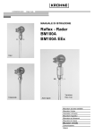
Fig. 2.1: OPTISONIC 7060
Applications
The OPTISONIC 7060 is ideally suited for a wide range of applications in process measurements,
such as
¾
¾
¾
Chemical and petrochemical industries
Power stations and other gas-consuming installations
Compressed air distribution systems.
Electrical & mechanical installation manual
730962.31.00
page 8 of 52
OPTISONIC 7060
2.2
Conformity, Configuration, Technical Data
2.2.1
CE Certificate
The OPTISONIC 7060 has been developed, manufactured and tested in accordance with the
following EC directives:
•
•
•
Pressure Equipment Directive 97/23/EC
Directive 94/9/EC (ATEX100)
EMC Directive 89/336/EC
Conformity with above directives has been verified and the equipment given the CE label.
2.2.2
Technical Data
Flow rate range
Meter size
DN 50
DN 65
DN 80
DN 100
DN 150
DN 200
DN 250
DN 300
DN 400
DN 450
DN 500
DN 600
•
2"
2,5"
3"
4"
6"
8"
10"
12"
16"
18"
20"
24"
Max gas
velocity
[m/s]
[ft/s]
57
187
57
187
57
187
53
174
45
148
43
141
45
148
32
105
30
98
30
98
30
98
30
98
Max flowrate
[m3/h] [ft3/h]
402
14197
680
24014
1000
35315
1600
56503
3000
105944
4800
169510
7800
275454
7800
275454
12000
423776
17170
606353
21200
748761
30550 1078993
Max flowrate @
Minimum flowrate
30m/s
[m3/h] [ft3/h]
[m3/h]
[ft3/h]
212 7486,74
7,1
249
357 12607,4
11,9
417
540
19070
18
630
900
31783
30
1050
2000
70629
67
2345
3360
118657
112
3920
5220
184342
174
6090
7380
260622
246
8610
12000
423776
400
14000
17170
606353
572
20020
21200
748761
707
24745
30550 1078993
1018
35630
Any flow rates given above are also valid in the bidirectional mode.
Electrical & mechanical installation manual
730962.31.00
page 9 of 52
OPTISONIC 7060
Other information
Meter characteristics
Number of measuring paths
Min. Gas velocity
Vmin/vmax
< DN80 (4”): 1; >= DN80: 2
1 m/s (for standard accuracy)
Min.: 1:30
Measuring medium
Gas
Pressure range
Temprature range
process gas, air
From ambient pressure to 103 bar; higher pressure on request
Standard: -25 °C to + 100 °C
Extended: -25 °C to +180 °C
Measuring accuracy
Reproducibility
Typical measuring uncertainty *
Outputs
Measuring quantities
Pulse and status outputs
Measuring rate
Interfaces
MODBUS (RS 485)
Explosion protection
Europe
Power supply
Operating voltage
Voltage limits
When supplied through solarpanel-fed battery
Typical power consumption
Ambient conditions
Temperature range
Storage temperature
Type of protection
Relative humidity
< 0.2 of the measured value
< ± 1% of measured value for a flowspeed > 1 m/s (3 ft/s) (2 acoustic path's)
< ± 2% of measured value for a flowspeed > 1 m/s (3 ft/s) (1 acoustic path)
Act. volume flowrate, act. volume, gas velocity, velocity of sound
Passive; electrically isolated; open collector; UImax = 30 V, IImax = 100 mA, fmax = 6
kHz, pulse width = 0.05…1 s or in accordance with NAMUR (EN50227)
20 measurements /s
ASCII protocol, for parameterisation, measured value inquiry and diagnosis
(9600,8, N.1)
II 2G EEx de ib [ia] IIA or IIC T4 in accordance with RL94/9/EG (ATEX) **
Ultrasonic signal converter intrinsically safe “ia”
Umin = 12 V DC, Umax = 28.8 V DC
Start-up voltage:
11.8V
Turn-off voltage for integrated total discharge protection: 10.8V
<1 W (approx. 37 mA at 24 V DC, approx. 66 mA at 12 V DC)
ATEX: - 20 °C to + 60 °C (- 40 °C to + 60 °C on request)
CSA: - 40 °C to + 60 °C
- 40 °C… + 60 °C
IP 67
< 95 %
* Related to the measured value in the range 0.1…1 Qmax with min. straight inlet length of 10
DN and min. straight outlet length of 5 D, for calibrated measuring system
Important
IMPORTANT
When used in hazardous areas, comply with the required type of explosion protection during
installation (intrinsically safe or increased safety)!
Electrical & mechanical installation manual
730962.31.00
page 10 of 52
OPTISONIC 7060
2.3
System Components
The OPTISONIC 7060 measuring system consists of the hardware components,
• Meter body
• Ultrasonic transducers
• CONVERTER (signal processing unit)
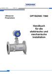
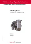
Fig. 2.3: OPTISONIC 7060
1.
2.
3.
4.
5.
2.3.1
Converter
Flange
Flowmeter body
Indication of positive flow direction
Transducer holder
Meter Body
The meter body consists of a section for mounting the ultrasonic transducers and flanges
used for installing in the pipeline.
Standard meter bodies are available in carbon steel and stainless steel.
The meter bodies can be delivered in several nominal sizes (see Section 2.2.4).
Electrical & mechanical installation manual
730962.31.00
page 11 of 52
OPTISONIC 7060
2.3.2
Ultrasonic Transducers
The OPTISONIC 7060 ultrasonic transducers are optimised to suit the system requirements.
The high quality of the transducer parameters provides the basis for accurate and highly
stable propagation time measurements with nanosecond precision. The ultrasonic
transducers are of an intrinsically safe design (class "ia").
2.3.3
Signal Processing Unit (CONVERTER)
The CONVERTER contains all the electrical and electronic components required for controlling the
ultrasonic transducers. It generates transmission signals and uses the received signals to
calculate the measured values. The CONVERTER also contains several interfaces for
communication
with a PC, or standardised process control system.
Event logging
see Section
2.7
The current volume counter value, fault, warning, and power failure alarms are stored in a
battery-buffered data memory (FRAM) along with the time of day. On system restart, the
counter value that was last saved is restored as the start value for the volume counter. The
FRAM back-up provides an unlimited number of writing cycles and protects the saved data
for at least 10 years.
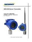
The CONVERTER is supplied with a front panel containing a two-line LCD to display current
measured
values, diagnosis and logbook information (see Fig. 2.4). You can select the values you
want to display using a magnetic pen while the front cover is kept closed (for details on
operation and menu structure see Section 8.2 in the appendix).
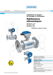
Fig. 2.4: Front panel for the OPTISONIC 7060 CONVERTER
1. Selected measured value / device status
2. Current measured value
3. Control area for operation by a magnetic pin
Electrical & mechanical installation manual
730962.31.00
page 12 of 52
OPTISONIC 7060
The connection terminals for the power supply and field connections are located on the
back of the CONVERTER in a separate terminal box (see Section 3.4.4).
The electronics units are mounted in a housing certified to EN 50018 or IEC 60079-1 with
type of protection "d" (flameproof enclosure). The transducer circuits are of an intrinsically
safe design (type "ia").
Electrical & mechanical installation manual
730962.31.00
page 13 of 52
OPTISONIC 7060
2.4
Operating modes and signal output
The OPTISONIC 7060 measuring system has the following operating modes:
¾ Measurement
Normal, fault-free system operation. The pulse and switching outputs, as well as the current
output are updated periodically. The “Warning” status signal may be set automatically
by the system in the course of the self-diagnosis (for details see Section 2.6).
¾ Check requested
This mode is active for multipath flowmeters only, if one measuring path has failed and the
adaptive path failure compensation has been activated. The measuring system compensates
for this failure but the measurement accuracy can be slightly reduced.
¾ Configuration
Mode for changing parameters and performing system tests. When this mode is active,
the measured values are considered to be invalid, although all the measurements and
calculations are carried out as in the "Measurement" mode (except system tests).
¾ Malfunction
This mode is activated when faults occur that prevent the system from measuring accurately.
If the cause for the fault ceases to exist, the system returns to "Measurement"
mode automatically.
Any operating modes are recorded in the logbook together with their respective activation
and deactivation time.
Output, signal
“Measured value”
“Check requested” *
Status signal
“Direction of flow” *
Status signal
“Warning”
Output value in operating mode
Measurement
Check requested
Frequency signal proportional to the volumetric flow
“open”
“closed”
Measurement valid
Compensation of a faulty
path (reduced accuracy)
“open”
“open”
positieve direction of
positieve direction of flow;
flow;
“closed”
“closed”
negative direction of flow
negative direction of
flow
If “Warning” active,
If “Warning” active, then
then digital output
digital output “closed”,
“closed”, else “open”
else “open”
Configuration
Malfunction
“open”, measurement fault *
“undefined”
“undefined”
“undefined”
“undefined”
“undefined”
“undefined”
LCD
3
>V 123456 m
3
<V
1234 m
3
>V 123456 m
3
<V
1234 m
Display flashing
Serial port RS485
•
•
•
OPTISONIC
7060
3
>V 123456 m
3
<V
1234 m
Display flashing
Measured value, diagnosis information and parameters
Measuring data logging, diagnosis and parameterisation
Connection with external process control equipment through implemented MODBUS protocol
(data polling)
* Output value can be changed by test commands.
Electrical & mechanical installation manual
730962.31.00
page 14 of 52
OPTISONIC 7060
The digital output 2 is assigned at the factory with the status signal “Check requested”, and
digital output 3 the status signal “Direction of flow”.
As a standard, the LCD shows the two major counters, one for each direction of flow.
Changes in the logbook status are indicated by a flashing character at the far right end of
the first line of the display. The character depends on the status:
•
•
•
“I” for information
“W” for warning
“E” for error
The character will disappear after acknowledgement. For details on reading the logbook
contents, acknowledgement and menu structure, refer to Section 8.2.4.
Electrical & mechanical installation manual
730962.31.00
page 15 of 52
OPTISONIC 7060
2.5
Self-diagnosis
In the measurement mode, the ratios of sound and path velocities, amplification settings,
and signal-to-noise are continuously monitored. If these parameters deviate from a preset
range, a warning signal is generated. This enables immediate measures to be taken to
prevent possible system malfunctions.
During commissioning or operation, you can adjust the signalling threshold values to suit
individual application requirements. This enables you to create the most effective status
warning system.
Note
Parameter
Velocity of
sound
Reception
gain
Signal-tonoise ratio
The "Warning" status signal does not affect the device function.
Default
threshold
value
< 5 m/s
Warning
message
Notes
Warning SOS
Deviation
This message is produced when the current measured path velocity of
sound deviates from the mean value of the mean velocities of sound
calculated for all the paths by more than the specified threshold value.
The current flow velocity is used as a weighting factor, so that
temperature stratification is disregarded at very low flow velocities. Used
to indicate whether or not the path is measuring the correct propagation
time.
Note
When setting the parameters, take into account plausible conditions for
normal operation (in particular temperature stratification).
The absolute difference between both path gain factors is evaluated and
must remain below the threshold value.
Important
High flow rates can also increase the difference in gain.
The absolute value of the reception gain is monitored.
Important
The current receiving sensitivity largely depends on the current process
pressure (inversely proportional in initial approximation, that is, when the
pressure doubles, the required receiving sensitivity is halved).
If one of the alarms is triggered by a path, this can indicate a malfunction
in the ultrasonic transducers, electronics, probe cables or parameter
settings (signal models, standard threshold values).
This alarm is activated when the signal-to-noise ratio is too small.
Reasons for this include interference noise caused by fittings in the
pipeline, valves that are not fully open, sources of noise near the
measuring location, or defective ultrasonic transducers.
< 6 dB
Warning AGC
Deviation
< 93 dB
Warning AGC
Limit
< 13 dB
Warning SNR
Additional signal and system diagnosis functions monitor the accuracy of the measured
values, by checking the plausibility of the ultrasonic signals received and the ultrasound
signal propagation times calculated from them.
Electrical & mechanical installation manual
730962.31.00
page 16 of 52
OPTISONIC 7060
2.6
Event logging
Important system events (max. 250) are stored in a verification logbook. Each entry consists
of the event, time stamp and the valid volume counter value along with acknowledgement
status present at the time the event occurred. The events are logged continuously in the
order they occur and, each event can be acknowledged manually. Logbook queries provide
information on the number of registered events and the remaining memory space. The
entries are classified as follows:
•
Active events
•
Inactive acknowledged and unacknowledged events
•
Acknowledged events
If there is no space left in the logbook, the logbook is closed and the system signals a fault.
Until the logbook is reset (deleted), the measured volumes are stored in the error volume
counters, in accordance with the direction of flow, irrespective of the measuring accuracy.
Overview of event entries
Name
Class
Description
Power On
“I”
information
System is cold started or rebooted after a
watchdog reset.
Change of
operating mode
“I”
information
Volume counter
reset
Error volume
counter reset
Counter overflow
“I”
information
“I”
information
“I”
information
“I”
information
System was changed to the configuration
mode after password input, or back from
the configuration mode to the
measurement mode. Parameter
modifications that affect the measured
values may have been carried out.
Resetting the volume counters to zero
Logbook reset
Set clock
Check requested
“I”
information
“W”
warning
Output range
“W”
warning
Measurement
invalid
“E” error
System error
“E” error
Resetting the error volume counters to zero
One of the four volume counters completed
its counter range.
Entire logbook was deleted (“Reset” is
always the first entry and indicated the
point of time the logbook was opened.)
Date and/ or time register of the real time
clock was/ were changed.
The measured value of one path must be
substituted by the replacement value
calculation routine.
The current measured value can no longer
be represented by the pulse output,
because the maximum output frequency
was reached.
More than one path must be substituted by
the replacement value calculation routine,
or the activated adaptive path failure
compensation is not yet active.
Safe operation of the system is not
guaranteed.
Electrical & mechanical installation manual
730962.31.00
Value
(second line on the display)
Time stamp of the last counter value stored is
considered to be the time of the “Power off”
event.
Activated password level
Reset volume
Reset volume
Time stamp of the change
Path index and cause for deactivation
Value is assigned with the four path states
Cause for the fault
• CRC program code
• CRC parameter
• CRC counter value
• CRC replacement path weights
• Implausible parameter
• DSP malfunction
page 17 of 52
OPTISONIC 7060
2.7
Configurations
Output
AO 0
Terminal
31, 32
DO 1
51, 52
DO 2
41, 42
DO 3
81, 82
Assignment
Measured value (current signal 4..20 mA) fault current signal at
configuration or malfunction
• Measured value (frequency signal)
• Direction of flow
• Malfunction
• Check requested
• Warning
• Measured value (frequency signal)
• Direction of flow
• Malfunction
• Check requested
• Warning
• Measured value (frequency signal)
• Direction of flow
• Malfunction
• Check requested
• Warning
Electrical & mechanical installation manual
730962.31.00
page 18 of 52
OPTISONIC 7060
3
Assembly and Installation
3.1
General Notes
3.1.1
Delivery
The OPTISONIC 7060 is delivered in a pre-assembled condition in robust packaging. When
unpacking the device,
check for possible damage in transit. Pay particular attention to the interior of the meter
body, any visible transducer components and the sealing surfaces of the flanges. Any
damage must be documented and reported to the manufacturer immediately.
Also check the consignment for completeness. The standard scope of delivery comprises:
¾
¾
¾
¾
OPTISONIC 7060 measuring system (meter body with CONVERTER and transducers)
Operating instructions (this document)
Documentation CD
Certificates
– OPTISONIC 7060 manufacturer information
– EC Declaration of Conformity
Important
IMPORTANT
Make sure the actual site conditions match the information provided on the labels at the
converter (see Fig. 3.1), in order to guarantee a safe operation of the measuring
equipment.
Fig. 3.1: OPTISONIC 7060 type plate label
Electrical & mechanical installation manual
730962.31.00
page 19 of 52
OPTISONIC 7060
3.1.2
Transport and Storage
Important
IMPORTANT
Only use the hoisting gear and auxiliaries (e.g. lifting straps) suitable for the weight to be
lifted. Max. load information can be found on the type plate of the hoisting gear. It is strongly
recommended to use the eye bolts supplied with the device only.
During OPTISONIC 7060 transport and storage operations, make sure that:
¾ The sealing surfaces of the flanges are protected with special caps
¾ The measuring device is firmly secures at all times
¾ Measures are taken to avoid mechanical damage
¾ Humidity and ambient temperature are within specified limits (see Section 2.2.4).
If the device is to be stored outside for more than one day, sealing surfaces of the flanges
and the interior of the meter body must be protected from corrosion, e.g. with Anticorit spray
(not required for stainless steel meter bodies). The same measure shall be taken if the
device is to be stored in dry condition, but for more than a week.
Note
3.2
Due to natural temperature fluctuation in the course of a day, or if the measuring device is
transported to a place with different temperature and humidity, moisture will condense on
any material. Carbon steel surfaces may corrode if left unprotected.
Assembly
Generally, the installation arrangement is specified during the project planning phase, i.e.
before installation of the system. Nominal width, material and type of flange should therefore
be defined in accordance with the design of the existing plant. It is particularly important that
the internal diameters of the meter body and adjacent pipelines are identical.
Fixing bolts, nuts and flange seals used must be suited to the operational conditions, and
comply with legal regulations and relevant standards.
Note
Any deviation from the planned design of the OPTISONIC 7060 and installation arrangement
shall be agreed with the supplier and documented prior to installing the measuring device.
Measuring location
•
•
•
•
•
The OPTISONIC 7060 can be installed in customary straight inlet and outlet pipes. The
adjacent pipes must have the same nominal width as the meter body. The internal
diameter can be derived from the marked flange standard and the type key information
(Appendix, Table 8.2). Any welding beads on the flanges of the inlet pipe shall be
flattened.
The meter body may be installed in horizontal or vertical position. In case of horizontal
installation, make sure that the meter body is adjusted so that the measuring planes are
in horizontal position. This aims to prevent dirt or moisture in the pipeline from entering the
transducer ports. Vertical installation is only possible if the measuring system is used for dry,
noncondensing gases. The gas flow must be free from any foreign material, dust and liquids.
Otherwise, filters and traps shall be used.
Avoid installations which may adversely affect the gas flow to be mounted directly
upstream the OPTISONIC 7060.
Seals at the flange connections between meter body and pipeline must not protrude into
the pipeline. Otherwise, the flow profile and thus the measuring accuracy may be
adversely affected.
Temperature measuring devices shall be fitted in the outlet pipe no closer than 1.5x DN,
or – in case of nominal widths of ≥ DN 400 – no closer than 300 mm.
Electrical & mechanical installation manual
730962.31.00
page 20 of 52
OPTISONIC 7060
Typical installation configuration:
Fig. 3.2: OPTISONIC 7060 installation in the pipeline for unidirectional use
1. Temperature measurement point
The choice of the installation configuration depends on type and extent of the flow
disturbance at the installation position (according to TR G13).
Type of disturbance
None
Elbow, reducer
Double elbow out of plane, T piece
Gas pressure controller with/ without muffler
Diffuser
Diffuser with swirling flow
Possible installation configuration
Configuration 1 (fig. 3.2)
Configuration 1 (fig. 3.2), >= 20 DN distance
from device and not “in sight” of the flowmeter
For bidirectional use, inlet and outlet section at both sides of the meter body shall be of
identical, independent of the configuration used (see Fig. 3.3). The temperature
measuring point shall in this case be installed at a distance of 5x DN to the meter body
(configuration 1),
Fig. 3.3: OPTISONIC 7060 installation in the pipeline for bidirectional use
1. Temperature measurement point
3.3
Mechanical Installation
Work on the pipelines in preparation to installing the gas flow meter is not included in the
scope of delivery.
It is recommended to use the following tools and auxiliaries for proper installation of the
OPTISONIC 7060:
•
•
•
•
•
Hoisting gear or fork lift (load capacity according to the weight information given on the
type plate)
Suitably sized ring wrench for flange mounting
Sealing and separating agents
Bolt lubricant
Leak detection spray
Electrical & mechanical installation manual
730962.31.00
page 21 of 52
OPTISONIC 7060
Warning
•
WARNING
3.3.1
•
•
Always observe the general safety regulations and safety instructions given in Section 1
when carrying out any assembly work.
The OPTISONIC 7060 must only be mounted to pressure-free and vented pipelines.
Take appropriate measures to avoid potential local or plant-specific dangers.
Choosing flanges, seals and other parts
Use pipeline flanges, bolts, nuts, and seals that withstand the maximum operational
pressure and temperature, as well as ambient and operational conditions (external and
internal corrosion) for the flange connections. For installation lengths and flange dimensions,
see Section 8.1.
Important
•
IMPORTANT
•
3.3.2
Always strictly observe the safety instructions for the installation of pressure equipment
including the connection of several pressure components set forth in the Pressure
Equipment Directive 97/23/EC.
Installation staff must be familiar with the directives and standards applicable for pipeline
construction.
Mounting the OPTISONIC 7060 to the pipeline
An arrow on the meter body indicates the main direction of flow. It is recommended to install
the OPTISONIC 7060 as indicated by this arrow id the device is to be used for unidirectional
flow applications. If the device is to be used in the bidirectional mode, the arrow indicates
the positive direction of flow.
Installation work to be carried out
¾
Take the OPTISONIC 7060 in the right position of the pipeline using the hoisting gear. Only
use the hoisting eyes provided to lift and transport the device. If you use lifting straps,
wrap them around the meter body.
Important
–
IMPORTANT
–
–
–
–
¾
¾
¾
¾
¾
Note
The hoisting eyes are designed for transporting the measuring device only. Do not lift
the OPTISONIC 7060 using these eyes when additional loads (such as blind covers, filling
for pressure tests) are attached.
Never attach hoisting gear to the signal processing unit or its mounting bracket and
avoid contact between these parts and the hoisting gear.
The OPTISONIC 7060 must not turn over or swing while being transported. Flange sealing
surfaces, CONVERTER housing and transducer cover caps may be damaged when the device
is hoisting gear is not attached properly.
Do not remove the caps protecting the sealing surfaces of the meter body flanges before
necessary.
Take suitable measures to prevent damage to the measuring device when carrying out
any work (welding, painting) in the vicinity of the OPTISONIC 7060.
Check the correct seat of the flange seals after inserting the first fixing bolts on both sides.
Align the OPTISONIC 7060 so that the mismatch between inlet pipe, meter body and outlet
pipe becomes as small as possible.
Insert the remaining fixing bolts and tighten the nuts cross-wise. Make sure to apply the
tightening torque specified in the project planning.
Mount the pressure line between pressure tap and pressure transmitter.
Fill the pipeline and check the OPTISONIC 7060 installed for leaks.
It is recommended to perform a leak test in accordance with the relevant regulations and
standards after completion of the mechanical installation.
Electrical & mechanical installation manual
730962.31.00
page 22 of 52
OPTISONIC 7060
3.3.3
CONVERTER alignment
The CONVERTER can be turned to a position which provides a good view on the display and good
conditions for cable routing (see Fig. 3.4). A stop on the housing prevents the CONVERTER from
being turned more than 330 . This aims to protect the cables from the meter body from
damage.
Fig. 3.4: Positioning the CONVERTER
1. Loosen the Allen screw, use 3 mm Allen key
2. Position the converter housing
3. Tighten the Allen screw
Note
Do not forget to tighten the Allan screw after positioning the CONVERTER.
Electrical & mechanical installation manual
730962.31.00
page 23 of 52
OPTISONIC 7060
3.4
Electrical Installation
3.4.1
General information
Pre-requisites
Wiring work (laying and connecting the power supply and signal cables) as a part of installing
the gas flow meter is not included in the scope of delivery. The mechanical installation
described in Section 3.3 must be completed. Comply with the minimum requirements of the
cable specs in accordance with Section 3.4.2.
Notes on cable laying
•
•
•
Cables shall be laid in conduits or on cable trays to provide protection from mechanical
damage.
Observe the permitted bending radiuses (generally, min. six times the cable diameter for
multi-lead cables).
Connections outside of conduits shall be as short as possible.
Warning
•
WARNING
•
•
3.4.2
Always observe the general safety regulations and safety instructions given in Section 1
when carrying out any installation work.
Installation work shall only be carried out by trained staff and in accordance with the
relevant regulations issued by the operating company.
Take appropriate measures to avoid potential local or plant-specific dangers.
Cable specs
Power supply 12 … 24 V DC
Type of cable
Min./ max. crosssectional area
Maximum cable length
Cable diameter
Specification
Tow leads
Notes
Connect shielding (if present) to
ground terminal
0.5 mm² / 1.5 mm²
Depending on loop resistance; min.
input voltage at the OPTISONIC 7060:
12 V
6 ... 12 mm
Peak current 150 mA
Fixing range of the cable glands
Digital output / current output
Specification
Notes
Type of cable
Twisted pair, shielded
Min./ max. crosssectional area
2 / 0.5 mm²
Connect shielding at other end to
ground terminal
Do not connect unused lead pairs
and prevent them form accidental
short-circuit.
Maximum cable length
Cable diameter
Loop resistance under load ≤ 250 Ω
6 ... 12 mm
Electrical & mechanical installation manual
730962.31.00
Fixing range of the cable glands
page 24 of 52
OPTISONIC 7060
Serial port
(RS485)
Type of cable
Min./ max. crosssectional area
Maximum cable length
Cable diameter
Specification
Notes
Twisted pair, shielded, impedance
approx. 120 Ω
2 x 0.5 mm2
Connect shielding at other end to
ground terminal
100 m at 0.5 mm²
200 m at 1.5 mm²
Do not connect unused lead pairs
and prevent them from accidental
short-circuit.
Fixing range of the cable glands
6 ... 12 mm
Electrical & mechanical installation manual
730962.31.00
page 25 of 52
OPTISONIC 7060
3.4.3
Checking the cable loops
To verify the cables to be correctly connected, check the cable loops. Proceed as follows:
• Disconnect both ends of the cable of the loop to be tested.
• This is to prevent connected devices from interfering with the measurement.
• Test the entire cable loop between CONVERTER and final device by measuring the loop
resistance.
• If you want to test the insulation resistance as well, you must disconnect the cables at
the electronics unit before using the insulation resistance tester.
Important
The test voltage applied would seriously damage the electronics unit!
IMPORTANT
•
Reconnect all cables after the loop resistance test.
Important
•
IMPORTANT
In non-intrinsically safe installations, only open the terminal boxes protected for use in
hazardous areas and connect/ disconnect cables when the system is disconnected from
the power supply.
• The front housing cover (with viewing panel) must only be opened when the system is
disconnected from the power supply and no less than 10 minutes after the system has
been switched off.
• Incorrect cabling may cause the OPTISONIC 7060 to fail.
This will lead to the annulment of any warranty claims. The manufacturer excludes any
liability for consequential damage.
Electrical & mechanical installation manual
730962.31.00
page 26 of 52
OPTISONIC 7060
3.4.4
Terminal box on the CONVERTER
Open the rear housing cover.
•
•
Loosen the securing bracket using a 3 mm Allan key.
Turn the rear housing cover in a counter-clockwise direction and take it off.
A schematic wiring diagram is provided on the inside of the rear housing cover (see also
Appendix, Section 8.3).
Fig. 3.6: CONVERTER housing, opening the cover
1. Housing cover
2. Securing bracket
Electrical & mechanical installation manual
730962.31.00
page 27 of 52
OPTISONIC 7060
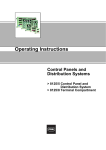
Fig. 3.7: Terminal box on the rear of the CONVERTER
1. Power supply, 2x1,5mm2 (UYCY or equivalent)
2. Digital output / current output, 4 x 2 x 0,5 mm2 (UYCY [TP] or equivalent)
3. Modbus, 4 x 2 x 0,5 mm2 (UYCY [TP} or equivalent)
4. HSK-K cable glands, M20 x 1,5 plastic (EU) or ½ In NPT (North America)
5. Cabel entry for internal 10-wire cable
6. 10-connection terminal strip for singal inputs and outputs
Electrical & mechanical installation manual
730962.31.00
page 28 of 52
OPTISONIC 7060
3.4.5
Connecting the OPTISONIC 7060 for use in non-hazardous areas
Assign the terminals in the CONVERTER terminal box (see Fig. 3.7) in accordance with the
following table.
Terminal box
Power supply
Field connections (10-channel terminal strip)
Fig. 3.8: Terminal assignment for use in non-hazardous areas
No.
Connection for
Function
Terminal
Value
1
2
3
Power supply
Analog output
Serial port
4
Digital output D0 1
Passive
Modbus
(RS 485)
Passive
5
Digital output D0 2
Passive
41, 42
6
Digital output D0 3
Passive
81, 82
Notes
1+, 231, 32
33, 34
12 ... 24 (+20 %) V DC
51, 52
fmax = 6 kHz, pulse duration 0.05 s - 1 s
Range:
Freely selectable number of pulses per volume unit
“closed”:
0 V ≤ UCEL ≤ 2 V, 2 mA ≤ICEL ≤ 20 mA (L=Low)
“open”:
16 V ≤ UCEH ≤ 30 V, 0 mA ≤ ICEH ≤ 0.2 mA (H =
High)
“closed”:
0 V ≤ UCEL ≤ 2 V, 2 mA ≤ICEL ≤ 20 mA (L=Low)
“open”:
16 V ≤ UCEH ≤ 30 V, 0 mA ≤ ICEH ≤ 0.2 mA (H =
High) “Check requested”
“closed”:
0 V ≤ UCEL ≤ 2 V, 2 mA ≤ICEL ≤ 20 mA (L=Low)
“open”:
16 V ≤ UCEH ≤ 30 V, 0 mA ≤ ICEH ≤ 0.2 mA (H =
High)
“Direction of flow”
(alternative “Warning”)
9600 Baud, 8 data bits, no parity, 1 stop bit
Electrical & mechanical installation manual
730962.31.00
Baud rate to be set
through software
With NAMUR
contact for
connection to
switching amplifier
(to DIN 19234)
page 29 of 52
OPTISONIC 7060
3.4.6
Operation in hazardous areas in accordance with Directive 94/9/EC (ATEX)
The power supply and field connections are designed with the increased type of protection
("e"). The transducer connections are of an intrinsically safe design ("ia").
All screw-type terminals as well as air and creepage distances of the OPTISONIC 7060 comply
with EN 50019.
Connection characteristics
Power supply connection
Field connections
Separate terminal box, separated from the field
connections with partition wall in the housing
and cover to EN 50020.
Cable routing via EExe cable gland, M5 ground
terminal integrated into housing section (cast).
Separate terminal box, separated from the
power supply connections with partition wall in
the housing and cover to EN 50020.
Cable routing via 2x EExe cable gland
Connection variants
The protection concept for the OPTISONIC 7060 permits the following connection variants:
• Power supply connection and field connections with increased type of protection ("e")
• Intrinsically safe power supply connection and field connections ("i")
• Power supply connection with increased type of protection ("e"), where the field
connections are intrinsically safe ("i")
The user must decide which variant to use, taking into account EN 60079-14.
A combination of intrinsically safe and non-intrinsically safe circuits is not permitted in the
terminal box for the field connections.
The rated voltage of non-intrinsically safe circuits is UM = 253 V.
Requirements regarding cabling in hazardous areas (Europe)
•
•
•
•
•
•
•
•
•
•
The cables must fulfill the requirements to EN 60079-14.
Cables that are subject to exceptional thermal, mechanical, or chemical loads must be
specially protected (e.g. laid in open-ended conduits).
Cables that are not fire protected must be verified to DIN VDE 0472, Part 804, test type
B with regard to fire resistance.
Attach ferrules to the wire ends to ensure that they do not split up.
The applicable requirements regarding air and creepage distances must be observed in
accordance with EN 50019. The available air and creepage distances in the terminal box
must not be reduced when connecting the cables.
Unused cable glands must be replaced by the EExe plugs supplied.
The equipotential bonding must be in accordance with EN 60079-14.
The meter body and CONVERTER housing must be connected to the potential equalizer.
In intrinsicallysafe circuits, install potential equalizers along the wiring runs of the current
outputs.
The applicable national specifications must also be observed.
Electrical & mechanical installation manual
730962.31.00
page 30 of 52
OPTISONIC 7060
Terminal assignment
Assign the terminals in the CONVERTER terminal box (see Fig. 3.7) in the same way as for the
OPTISONIC 7060 in non-hazardous areas (see table in Section 3.4.5).
Important
IMPORTANT
The protective conductor must not be connected within the hazardous area. For
measurement reasons, the equipotential bonding must, as far as possible, be identical to
the pipeline potential. Additional grounding with the protective conductor PE via the
terminals is not permitted!
Notes for safe operation in hazardous areas
Approval of the
ultrasonic transducers
in zone 0 only valid for
operation under
atmospheric conditions.
•
•
•
•
•
•
•
•
Protection against explosion: II 2G EEx de ib [ia] IIC T4 or II 2G EEx de ib [ia] IIA T4
Ambient temperature: -20°C to +60°C
In the extended temperature range from -40 C to +60 C, only use metal cable glands.
The cable glands delivered are black. If connections are wired with intrinsically safe
circuits, it is recommended to replace these with the light-blue cable connections (RAL
5015) provided.
For the temperature class according to the ambient and media temperature, see the EC
Type Examination Certificate.
The type of protection for the field and power supply connections is determined by the
external circuits that are connected (for options see "Connection variants").
Safety-relevant data for intrinsically safe circuits is provided in the EC Type Examination
Certificate.
Ensure that the power supply connection cover is properly sealed. In intrinsically safe
installations, the terminal box can be opened and cables connected and disconnected
while the system is live.
If the meter body is insulated, the CONVERTER housing must not be insulated.
Important
IMPORTANT
Always observe the temperature specifications for use in hazardous areas.
Electrical & mechanical installation manual
730962.31.00
page 31 of 52
OPTISONIC 7060
Fig. 3.9: Explosion protection of the OPTISONIC 7060 components
1. Power supply
2. I/O connections
Electrical & mechanical installation manual
730962.31.00
page 32 of 52
OPTISONIC 7060
Safety-relevant data of inputs and outputs
Output circuit
Intrinsically safe EEX ia IIA / IIB / IIC
Active current output
Terminals 31/32
Passive current
output
Terminals 31/32
Digital output
Terminals 51/52,
41/42, 81/82
RS 485
Terminals 81/82
PROFIBUS PA
Terminals 33/34
Ultrasonic
transducer
connections
Uo = 22.1 V
Io
Po
EEx ia IIA
EEx ia IIC
[mA]
[mW]
Co [nF]
Lo [mH]
Co [nF]
Lo [mH]
155 / 155
857 / 857
4100
7
163
1
Characteristic curve: linear
Internal capacity CI = 4 nF, internal inductance LI = 0.075 mH
Only for connection to passive, intrinsically safe circuits or intrinsically safe
circuits with the following maximum values: UI = 30 V
UI = 30 V
CI = 4 nF
II = 100 mA
LI = 0.075 mH
PI = 750 mW
CI = 4 nF
UI = 30 V
II = 100 mA
LI = 0.075 mH
PI = 750 mW
Characteristic curve: linear
UI = 10 V
Uo = 5.88 V
Io = 313 mA
II = 275 mA
Po = 460 mW
PI = 1420 mW
Co = 1000 µF/43 µF
Lo = 1.5/0.2 mH
UI = 30 V
II = 100 mA
PI = 750 mW
EEx ia IIA
EEx ia IIB
EEx ia IIC
Characteristic curve: linear
Uo = 51.2 V
Uo = 38.9 V
Max. transmission voltage Uo = 60.8 V
Io = 80 mA
Io = 60 mA
Short-circuit current Io = 95 mA
Po = 1024 mW
Po = 584 mW
Po = 1444 mW
Co = 187 nF
Co = 34 nF
Co = 300 nF
Non-intrinsically
safe UM = 253 V
UB = 18 V
IB = 35 mA
UB = 30 V
IB = 35 mA
UB = 30 V
IB = 100 mA
UB = 5 V
IB = 175 mA
Special conditions
For connection to a NAMUR amplifier, the digital output (terminals, 51/52, 41/42,
81/82) can be wired internally as a NAMUR contact by setting a jumper (for details see
Service manual). Open Collector or NAMUR configuration is carried out at the factory in
accordance with the order details. If no configuration was specified in the purchase order,
the digital output is configured as Open Collector.
Digital output as Open Collector
Digital output in accordance with NAMUR
Fig. 3.10: Wiring digital outputs
Electrical & mechanical installation manual
730962.31.00
page 33 of 52
OPTISONIC 7060
3.4.7
Operation in hazardous areas to North American Guidelines (CSA)
The system must be installed as shown in Fig. 8.3 to Fig. 8.5 in the appendix. The notes
provided in Fig. 8.3 and Fig. 8.4 must be observed at all times.
Installation in Division 1 / Zone 0 / Zone 1
The following applies to devices installed in this area and that are connected to the
UFC 060 electronics installed in Division 1 / Zone 1:
The maximum device voltage must not exceed 125 V.
You must observe the applicable national regulations, such as:
– In the USA, the device must be installed in accordance with NEC (ANSI/NFPA 70 and
ANSI/ISA RP 12.6.)
– In Canada, the conditions according to CEC part 1 apply.
Exchanging components impairs the intrinsic safety.
In intrinsically safe installations (Entity system), only equipment certified to CSA safety
barriers, or other CSA equipment that fulfills requirements regarding the Entity system,
must be used (Voc ≤ Vmax, Isc ≤ Imax.,
Ca ≥ Ci + Ccable, La ≥ Li + Lcable).
Installation in Division 2 / Zone 2
Installation to CEC or NEC
IMPORTANT
Important
Danger of explosion: Do not loosen any components without switching the power supply
off beforehand or where it states that the area is potentially explosive.
Exchanging components affects compatibility with Class 1, Division 2.
Electrical & mechanical installation manual
730962.31.00
page 34 of 52
OPTISONIC 7060
4
Operation of the converter
4.1
Operation and menu structure of the CONVERTER with LCD
4.1.1
Operation
The current measurement, volume counter, and diagnosis values can be displayed on the
two-line LCD on the front of the CONVERTER. You can select the values you want to display using
a magnetic pen while the front cover is kept closed or using the buttons while the front cover
is open (see Fig. 8.2).
Important
IMPORTANT
When the CONVERTER housing is open, there is no EMC protection or protection against electric
shock!
Fig. 4.1 : Front panel with LCD
1.
2.
3.
Selected measured value / device status
Current measured value
Control area for operation by a magnetic pin
The control panels and buttons have the following functions:
•
C/CE control panel/ button
Used to call up the menu from the measured value display. Within the menu, you can go
back a level, or return from the top level menu to the measured value display.
Electrical & mechanical installation manual
730962.31.00
page 35 of 52
OPTISONIC 7060
•
•
•
4.1.2
STEP control panel/ button
Used to scroll forward in the menu.
DATA control panel/ button
Used to scroll backward in the menu.
ENTER function
Used to select a menu level, to acknowledge log book entries and to reset the error
volume counter.
– Magnetic pen operation:
The ENTER function is executed when you hold the pen on the DATA/ENTER control
panel for at least 2 s.
– Button operation:
The ENTER function is executed by pressing STEP and DATA simultaneously.
Alternatively, you can press the DATA button for at least 2 s.
Menu structure
You can call up information, acknowledge logged events and reset the error volume
counters in the display menu, using the control panels and buttons described
above.
Electrical & mechanical installation manual
730962.31.00
page 36 of 52
OPTISONIC 7060
Electrical & mechanical installation manual
730962.31.00
page 37 of 52
OPTISONIC 7060
Electrical & mechanical installation manual
730962.31.00
page 38 of 52
OPTISONIC 7060
4.1.3
Definition of measured value displays
Each line of the LCD can be configured separately as regards the measured value shown.
In addition, the display lines may be configured with a multiplex layout (shifted LCD content).
If this configuration is active, the two display contents are shown alternately (display
changes every 5 s).
Display
>Qv 1000.0 m3/h
Operating volume flow rate
“>” forward
“<” reverse
>V 1234567 m3/h
Forward volume counter value
<V 1234567 m3/h
Reverse volume counter value
>EV 1234567 m3/h
Forward error volume counter value
<EV 1234567 m3/h
Reverse error volume counter value
VOG 20.23 m/s
SOS 343.15 m/s
Average flow velocity (velocity of gas)
Average velocity of sound (speed of sound)
Electrical & mechanical installation manual
730962.31.00
page 39 of 52
OPTISONIC 7060
4.1.4
Definition of log book entries
1. Classification
The entries are distinguished into three classes and identified by the initial character in the
first line.
• “I” Information
• “W” Warning
• “E” Error/ malfunction
2. Type of occurrence
•
•
“S+” Point in time of the event identifying the beginning of a state
“S-” Point in time of the event identifying the end of a state
3. Overview of event entries
Name
Power on
Class
I
Description
System is cold started or rebooted after a watchdog
reset.
Value
Time stamp of the last stored
counter value is considered to
be the time of the “Power off”
event.
I
System was changed to the configuration mode after
password input, or back from the configuration mode to
the measurement mode.
Parameter modifications that affect the measured
values may have been carried out.
Activated password level.
I
Date and/or time register of the real time clock
was/were changed.
Time stamp of the change.
I
Resetting the volume counters to zero.
Counter value at the time of
the event.
I
Resetting the error volume counters to zero.
Counter value at the time of
the event.
I
One of the four volume counters has run through
completely.
I
Entire log book was deleted
(“Reset” is always the first entry and indicates the point
in time the log book was opened.)
W
The measured value of one path must be substituted by
the replacement value calculation routing.
I Power supply
April 18, 2003
12:13
Change of
operating mode
I Operation
Password 2
S+
Set clock
I Real time clock
April 18, 2003
12:13
Volume counter
reset
I Reset V
S+
Error volume
counter reset
I Reset V
S+
Counter overflow
I Overflow
S+
Log book reset
I Reset Log
S+
Check requested
W Check re.
Path no.
Path index
S+
Electrical & mechanical installation manual
730962.31.00
page 40 of 52
OPTISONIC 7060
Name
Output range
W Output
Class
W
S+
Measurement
invalid
E
More than one path must be substituted by the
replacement value calculation routine, or the activated
adaptive path failure compensation is not yet active.
E
Safe operation of the system is not guaranteed.
E Measurement
S+
Path
System error
E System
Parameter
Description
The current measured value can no longer be
represented by the pulse output, because the maximum
output. frequency was reached.
S+
4.1.5
Acknowledgement of a log book entry
4.1.6
Resetting the error volume counters
Electrical & mechanical installation manual
730962.31.00
Value
Cause of the fault
• CRC program code
• CRC parameters
• CRC counter value
• CRC replacement path
weights
• Parameters (implausible)
• DSP
page 41 of 52
OPTISONIC 7060
5
Verification and Commissioning
5.1
Verification
5.1.1
o
o
5.1.2
Examining the condition
The following conditions must be fulfilled before you can start the verification procedure for
the OPTISONIC 7060:
CONVERTER: Make sure there is no visible sign of damage, in particular to the sealing surfaces
and the internal contours of the connection flanges.
The meter body must be approved for the max. test pressure that is to be applied.
Testing the functions
Check that the OPTISONIC 7060 is properly installed mechanically and electrically, as detailed
in Section 3, to ensure successful commissioning.
The major system parameters have been configured at the factory. The default settings
should allow trouble-free operation of the ultrasonic gas flow meter.
Checking without PC and MEPAFLOW IV control and diagnosis software
The information listed below is shown directly on the LCD of the OPTISONIC 7060 (for details
on the menu structure and operation with a magnetic pen, see chapter 4).
5.2
Commissioning
5.2.1
Installation
Install the OPTISONIC 7060 in the line at the measurement position after completion of the
calibration. The necessary working steps are detailed in Section 3. Observe the safety
instructions provided in that Section.
5.2.2
Checking the functions
The current values of the operating volume counters (forward and reverse) are shown on
the LCD (see Appendix, Section 6.2.2). If these values are displayed continuously, the
OPTISONIC 7060 is working correctly. A flashing display indicates a warning state or fault, which
should be analysed as described in Section 6.
Fasten the magnetic pen which is part of the measuring system and which is used to
operate the LCD on the CONVERTER using the strap provided on the OPTISONIC 7060 so that it
cannot be lost.
Electrical & mechanical installation manual
730962.31.00
page 42 of 52
OPTISONIC 7060
5.2.3
Pressure testing of a gas pipeline with liquid (water)
For example when a pipeline in which the OPTISONIC 7060 is installed will be pressure tested with
a liquid (water) the following precautions must be taken to prevent the transducers from getting wet:
• The transducers must be removed.
• Blindstops must be fitted in the tranducer positions. A set of blindstops can be ordered at
KROHNE.
For the detailed procedure to remove and refit the transducers, consult the service manual.
Electrical & mechanical installation manual
730962.31.00
page 43 of 52
OPTISONIC 7060
6
Maintenance
6.1
General
The OPTISONIC 7060 does not contain any components that move mechanically. Meter body
and ultrasonic transducers are the only components that come into contact with the
gaseous media. Titanium and high-quality stainless steel ensure that these components are
resistant to corrosion, provided that the device is implemented in accordance with the
relevant specifications. This means that the OPTISONIC 7060 is a low-maintenance system.
Maintenance essentially involves routine checks to determine the plausibility of the
measured and diagnosis values calculated by the system.
It is recommended to record a diagnosis and status log on a regular basis (see software
manual) and compare these values with the initial situation when the system was
commissioned. The operating conditions (gas composition, pressure, temperature, flow
velocity) of the individual logs should be comparable or documented separately and taken
into account when the comparison is evaluated.
6.2
Routine checks
You can check the front panel of the OPTISONIC 7060 to ensure that the system is
functioning properly (see Section 4.3).
The routine checks relate to the following values (see also the table below and Section 6).
Velocity of sound
The velocity of sound measured is usually highly stable. Sudden changes in the measured
value can indicate signal detection problems, which can affect propagation time
measurements, or changes in the gas composition. A theoretical velocity of sound value can
be calculated by analysing the gas or recording the pressure and temperature during log
measurement. Implausible measurements can then be indicated by comparing theoretical
and measured velocity of sound values and identifying any marked discrepancies. The
velocity of sound values in the paths should also be approximately equal.
Number of rejected measurements
The number of rejected measurement (% inaccurate measurement) for the measuring
path(s) should be as close to 0 % as possible, although this largely depends on the flow
velocity. With high flow velocities, the figure can be as high as 50% without affecting
accuracy. Marked discrepancies in the values under similar conditions (pressure,
temperature, gas flow rate, gas composition) indicate that changes have been made to the
device or plant (e.g. malfunctions caused by a valve that is not fully open).
Receiving sensitivity
The receiving sensitivity set by the device largely depends on the process pressure. Under
normal conditions, this value is highly stable. The difference between the ultrasonic
transducers for a measuring path is small, although it can increase with greater velocities.
Significant fluctuations in the receiving sensitivity indicate a low-quality receiving signal. A
significant increase under similar process conditions is normally caused by contamination
on the ultrasonic transducers (for instructions on cleaning them, see the service manual).
Signal-to-noise ratio
These values are typical for the plant and do not change, providing the conditions remain
the same. A reduction in the signal-to-noise ratio with similar reception sensitivity indicates
sources of acoustic interference (e.g. pressure regulator) near the measuring location.
Electrical & mechanical installation manual
730962.31.00
page 44 of 52
OPTISONIC 7060
Overview of the typical values
Parameter
Velocity of sound
Standard value
Deviation from the
theoretical velocity of
sound less than ± 0.3 %
Error
Greater than ± 0.3 %
The differences
between the velocities
of sound in the paths
should not be greater
than ± 1.5 m/s.
~20 dB
This depends on the
nominal width of the
meter body and the
current process
pressure.
Greater than ± 1.5 m/s
Receiving sensitivity /
AGC level
This depends on the
nominal width of the
meter body and the
current process
pressure.
Significant deviations
(greater than 50%) from
the historical data with
similar process
pressures
Number of rejected
measurements
< 5 % with zero point
< 35 % with flow
Permanently greater
than 50%
Signal-to-noise ratio
Permanently less than
10 dB
Comments
When calculating the
theoretical velocity of
sound, you must take
special care to ensure
that the gas
composition, pressure
and, in particular, the
temperature are the
same as at the
measuring location
when the log was
recorded.
Temperature
stratification can occur
with low flow rates.
Possible sources of
interference include
electrical noise caused
by bad contacts on the
connectors or sources
of acoustic interference,
such as control valves
or very high flow
velocities.
The receiving sensitivity
is inversely proportional
to the process
pressure: when the
pressure doubles, the
sensitivity halves.
Deviations from the standard values specified in the table can indicate a malfunction. In
addition to diagnosing the error (as described in Section 6), you can also create a diagnosis
and status log and send this to KROHNE for analysis (see software manual).
Electrical & mechanical installation manual
730962.31.00
page 45 of 52
OPTISONIC 7060
7
Troubleshooting
If the routine checks described in Section 5.2 or the functional checks described in Section
4.1.2 indicate that the device is not functioning properly, the following table will help you
diagnose the fault. If you still cannot find the cause for the fault, you can use the
ALTO IV program to carry out a more detailed fault diagnosis (see software manual, service
manual).
Display, parameter
• No display
• No pulse frequency
• No active status
signal
“Warning” on the
LCD
Different velocities of
sound in the
individual paths
Implausible sound
velocity
• Lower signal-tonoise ratio and
reception sensitivity
• Increased number
of rejected
measurements in
individual paths
Increased reception
sensitivity
Increased number of
rejected
measurements in all
paths
Possible cause
Faulty power supply
Defective device
Transducer(s) are
dirty
Transducer(s) are
defective
Cabling swapped
when transducer was
cleaned
Transducer or
electronics fault
Gas analysis,
pressure or
temperature
measurement
incorrect
Transducer(s)
damaged during
maintenance
Additional sources of
noise due to a valve
that is not fully open,
fittings, noise sources
near the device
Different gas
composition or
process pressure
Transducer(s) are
dirty
Additional noise
sources
Corrective action
• Check the input voltage at terminals 1 and 2
• Check cables and terminal connections
Important
Take the relevant safety precautions!
Contact the manufacturer
Clean the transducer(s)
Replace the transducer(s) (see service manual)
Check and, if necessary, correct
Replace the transducer(s) (see service manual)
Note
Temperature stratification can result in differences
between the individual paths, especially with very low
flow (higher temperatures generate higher velocities of
sound). Even when the plant is being filled or when it is
shut down, different velocities of sound can occur on
the individual paths as a result of gas stratifications.
Replace the transducer(s) (see service manual)
Check the measurement plausibility and number of
rejected measurements and, if necessary, remove
noise sources.
No work required on the device
Clean the transducer(s)
Remove noise sources
Gas velocity outside
the measurement
range
Electrical & mechanical installation manual
730962.31.00
page 46 of 52
OPTISONIC 7060
8
ATEX / CSA converter terminal assignment
8.1
Converter terminal assignments ATEX
Fig. 8.1: Terminal assignment in accordance with ATEX IIA
Fig. 8.2: Terminal assignment in accordance with ATEX IIC
Electrical & mechanical installation manual
730962.31.00
page 47 of 52
OPTISONIC 7060
8.2
Converter terminal assignments CSA
Fig. 8.3: Terminal assignment in accordance with CSA Group D
Fig. 8.4: Terminal assignment in accordance with CSA Group BCD
Electrical & mechanical installation manual
730962.31.00
page 48 of 52
OPTISONIC 7060
Fig. 8.5: Control drawing CSA 781.00.02 (page 1)
Electrical & mechanical installation manual
730962.31.00
page 49 of 52
OPTISONIC 7060
Fig. 8.6: Control drawing CSA 781.00.02 (page 2)
Electrical & mechanical installation manual
730962.31.00
page 50 of 52
OPTISONIC 7060
Fig. 8.7: Control drawing CSA 781.00.02 (page 3)
Electrical & mechanical installation manual
730962.31.00
page 51 of 52
Australia
KROHNE Australia Pty Ltd.
Unit 19 No. 9, Hudson Ave.
Castle Hill 2154, NSW
TEL.: +61(0)2-98948711
FAX: +61(0)2-98994855
e-mail: [email protected]
Austria
KROHNE Ges.m.b.H.
Wagramerstr. 81
Donauzentrum
A-1220 Wien
TEL.: +43(0)1-2 03 45 32
FAX: +43(0)1-2 03 47 78
e-mail: [email protected]
Belgium
KROHNE Belgium N.V.
Brusselstraat 320
B-1702 Groot Bijgaarden
TEL.: +32(0)2-4 66 00 10
FAX: +32(0)2-4 66 08 00
e-mail: [email protected]
Brazil
KROHNE Conaut
Controles Automaticos Ltda.
Estrada Das Águas Espraiadas, 230 C.P: 56
06835 - 080 EMBU - SP
TEL.: +55(0)11-4785-2700
FAX: +55(0)11-4785-2768
e-mail: [email protected]
China
KROHNE Measurement Instruments Co. Ltd.
Room 7E, Yi Dian Mansion
746 Zhao Jia Bang Road
Shanghai 200030
TEL.: +86(0)21-64677163
FAX: +86(0)21-64677166
Cellphone: +86(0)139 1885890
e-mail: [email protected]
CIS
Kanex KROHNE Engineering AG
Business-Centre Planeta, Office 403
ul. Marxistskaja 3
109147 Moscow/Russia
TEL.: +7(0)095-9117165
FAX: +7(0)095-9117231
e-mail: [email protected]
Czech Republic
KROHNE CZ, spol. s r.o.
Dráz?ní 7
62700 Brno
TEL.: +42(0)5-45513340 / 341
FAX: +42(0)5-45513339
e-mail: [email protected]
France
KROHNE S.A.
Usine des Ors
B.P. 98
F-26 103 Romans Cedex
TEL.: +33(0)4-75 05 44 00
FAX: +33(0)4-75 05 00 48
e-mail: [email protected]
Germany
KROHNE Messtechnik
GmbH & Co. KG
Ludwig-Krohne-Straße
D-47058 Duisburg
TEL.: +49(0)203-301-0
FAX: +49(0)203-301 389
e-mail: [email protected]
Norway
Krohne Instrumentation A.S.
Ekholtveien 114
NO-1526 Moss
P.O. Box 2178, NO-1521 Moss
TEL.: +47(0)69-264860
FAX: +47(0)69-267333
e-mail: [email protected]
Internet: www.krohne.no
South Africa
KROHNE Pty. Ltd.
163 New Road
Hulway House Ext. 13
Midrand
TEL.: +27(0)11-315-2685
FAX: +27(0)11-805-0531
e-mail: [email protected]
India
KROHNE Marshall Ltd.
A-34/35, MIDC
Industrial Estate; ‘H’-Block,
Pimpri Pune 411018
TEL.: +91(0)20 -747 01 21
TEL.: +91(0)20 -747 01 71
FAX: +91(0)20 -747 70 49
e-mail: [email protected]
Spain
I.I. KROHNE Iberia, S.r.L.
Poligono Industrial Alcalá I
Calle El Escorial, Nave 206
E-28805 Alcalá de Henares -Madrid
TEL.: +34(9)1-8 83 21 52
FAX: +34(9)1-8 83 48 54
e-mail: [email protected]
Italy
KROHNE Italia Srl
Via V. Monti 75
I-20145 Milano
TEL.: +39(0)2-4 30 06 61
FAX: +39(0)2-43 00 66 66
e-mail: [email protected]
Switzerland
KROHNE AG
Uferstr. 90
CH-4019 Basel
TEL.: +41(0)61-638 30 30
FAX: +41(0)61-638 30 40
e-mail: [email protected]
Korea
Hankuk KROHNE
2 F, 599-1
Banghwa-2-Dong
Kangseo-Ku
Seoul
TEL.: +82(0)2665-85 23-4
FAX: +82(0)2665-85 25
e-mail: [email protected]
United Kingdom
KROHNE Ltd.
Rutherford Drive
Park Farm Industrial Estate
Wellingborough,
Northants NN8 6AE, UK
TEL.: +44(0)19 33-408 500
FAX: +44(0)19 33-408 501
e-mail: [email protected]
Netherlands
KROHNE Altometer
Kerkeplaat 12
NL-3313 LC Dordrecht
TEL.: +31(0)78-6306300
FAX: +31(0)78-6306390
e-mail: [email protected]
USA
KROHNE Inc.
7 Dearborn Road
Peabody, MA 01960
TEL.: +1-978 535-60 60
FAX: +1-978 535-17 20
e-mail: [email protected]
KROHNE Persenaire B.V.
Kerkeplaat 12
NL-3313 LC Dordrecht
TEL.: +31(0)78-6306200
FAX: +31(0)78-6306234
Service Direkt: +31(0)78-6306222
e-mail: [email protected]
Overseas Representatives
Algeria
Argentina
Bulgaria
Camaroon
Canada
Chile
Columbia
Croatia
Denmark
Ecuador
Egypt
Finland
French Antilles
Greece
Guinea
Hong Kong
Hungary
Indonesia
Ivory Coast
Iran
Ireland
Israel
Japan
Jordan
Kuwait
Marocco
Mauritius
Mexico
New Zealand
Pakistan
Poland
Portugal
Saudi Arabia
Senegal
Singapore
Slovakia
Slovenia
Sweden
Taiwan
Thailand
Turkey
Tunesia
Venezuela
Yugoslavia
Other Countries:
KROHNE Messtechnik
GmbH & Co. KG
Ludwig-Krohne-Str.
D-47058 Duisburg
TEL.: +49(0)203-301 309
FAX: +49(0)203-301 389
e-mail: [email protected]
Subject to change without notice