1
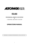
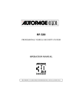
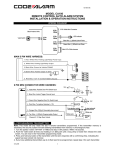
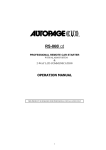
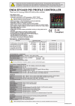
RF-425LCD
PROFESSIONAL VEHICLE SECURITY SYSTEM
INSTALLATION MANUAL
(FOR AUTHORIZED DEALERS ONLY)
THIS PRODUCT IS DESIGNED FOR PROFESSIONAL INSTALLATION ONLY
1
BLUE...TRUNK/HOOD TRIGGER (-) INPUT
BLACK/BLUE...4TH CHANNEL OUTPUT
(200mA)
RF-425
VIOLET...POSITIVE TRIGGER (+) INPUT
YELLOW...IGNITION INPUT
5 - PIN
GREEN...NEGATIVE TRIGGER (-) INPUT
10A
WHITE...(+) LIGHT FLASH
ORANGE...STARTER INTERUPT OUTPUT
(RELAY REQUIRED)
BLACK...(-) MAIN SYSTEM GROUND
PINK...2 STEP DOOR UNLOCK
(RELAY REQUIRED)
BROWN...(+) SIREN OUTPUT
WHITE/BLUE...3RD CHANNEL OUTPUT
(200mA)
GRAY...2ND CHANNEL OUTPUT
15A
(200mA)
RED...12V (+) MAIN POWER
WHITE...DOME LIGHT OUTPUT
+
(RELAY REQUIRED)
10 - PIN
-
BATTERY
BLUE/BLACK...(-) HORN OUTPUT
RF-425
WHITE CONNECTOR
Orange Port 1
Dual Shock
White Port 2
Optional Sensor
Super Bright LED Status Indicator
Valet/Override Switch
BLUE CONNECTOR
BROWN UNLOCK SWITCH... N/C (87a)
Standard Relay
For Refference
BLUE UNLOCK MOTOR... COMMON (30)
NORMALLY OPEN (N/O)
87
oooo
VIOLET UNLOCK... N/O (87)
87a
30
WHITE LOCK SWITCH...N/C (87a)
20A
VIOLET/RED LOCK... N/O (87)
System
Antenna
(No Connections)
6-PIN
For Technical Assistance Call (800) 945-2527
COMMON
The coil contacts (85 & 86) are not needed
as they are controlled within the main unit.
GREEN LOCK MOTOR... COMMON (30)
1-Way AM
Transmitting
Antenna
NORMALLY CLOSE (N/C)
WIRING HARNESS
MAIN 5 PIN WIRE HARNESS:
5 - PIN
10A
WHITE...(+) LIGHT FLASH
BLACK...(-) MAIN SYSTEM GROUND
BROWN..(+) SIREN OUTPUT
15A
RED...12V (+) MAIN POWER
+
-
BATTERY
BLUE/BLACK...(-) HORN OUTPUT
10 PIN MINI CONNECTOR WIRE HARNESS:
BLUE...TRUNK/HOOD TRIGGER (-) INPUT
BLACK/BLUE...4TH CHANNEL OUTPUT
VIOLET...POSITIVE TRIGGER (+) INPUT
YELLOW...IGNITION INPUT
GREEN...NEGATIVE TRIGGER (-) INPUT
ORANGE...STARTER INTERUPT OUTPUT
(RELAY REQUIRED)
PINK...2 STEP DOOR UNLOCK
(RELAY REQUIRED)
WHITE/BLUE...3RD CHANNEL OUTPUT
(200mA)
GRAY...2ND CHANNEL OUTPUT
(200mA)
WHITE...DOME LIGHT OUTPUT
(RELAY REQUIRED)
6 PIN DOOR LOCK WIRE HARNESS:
BROWN UNLOCK SWITCH... N/C (87a)
Standard Relay
For Refference
BLUE UNLOCK MOTOR... COMMON (30)
87
VIOLET UNLOCK... N/O (87)
87a
30
WHITE LOCK SWITCH...N/C (87a)
NORMALLY CLOSE (N/C)
COMMON
The coil contacts (85 & 86) are not needed
as they are controlled within the main unit.
GREEN LOCK MOTOR... COMMON (30)
20A
VIOLET/RED LOCK... N/O (87)
NORMALLY OPEN (N/O)
WIRING
Keep wiring away from moving engine parts, exhaust pipes and high-tension cable. Tape
wires that pass through holes on the firewall to prevent fraying. Be careful of sharp edges
that may damage wires and causes short circuit.
CAUTION: Do not connect the wire harness to the control module until all wiring to vehicle
is complete.
MAIN 5 PIN WIRE HARNESS:
WHITE WIRE –PARKING LIGHT RELAY OUTPUT (+12 V 10A OUTPUT) -Connect the WHITE wire to the parking light wire coming from the headlight switch. Do
not connect the WHITE wire to the dashboard lighting dimmer switch. (Damage to the
dimmer will result). The limitation of the WHITE wire is 10 AMP max. Do not exceed this
limit or damage to the alarm and parking relay will result.
BLACK WIRE -- SYSTEM GROUND –
This is main ground connection of the alarm module. Make this connection to a solid
section of the vehicle frame. Do not connect this wire to any existing ground wires
supplied by the factory wire loom, make the connection to the vehicle's frame directly.
BROWN WIRE-- (+) SIREN OUTPUT
This is the positive (+) output connection for the siren. Current capacity is 2 amps. Make
connection to the (+) red wire from the siren. Make the (-) black wire coming from the
siren to a good chassis ground.
RED WIRE -- SYSTEM POWER (+12V CONSTANT) -The RED wire supplies power to the system. Connect this wire to a constant +12 volt
source.
BLUE / BLACK WIRE -- (-) HORN OUTPUT -This wire is provided to use the existing vehicle's horn as the alarm system's optional
warning audible device. It's a transistorized low current output, and should only be
connected to the low current positive (-) output from the vehicle's horn switch.
4 PIN ORANGE CONNECTOR FOR 2 STAGE SHOCK SENSOR
4.
3.
2.
1.
Green Wire / Warn Away Input
Blue Wire / Zone 4 Ground Trigger
Black Wire / Negative
Red Wire / +12Volts
Function: For both Orange Port 1 and White Port 2, Allows easy positive, negative, instant
trigger, and warn-away trigger connection with quick disconnect ability for other detection
devices.
4
10-PIN MINI CONNECTOR WIRE HARNESS.
1. BLUE WIRE -- GROUND INSTANT TRIGGER INPUT -This wire is the ground trigger input wire for hood/trunk pin switches.
2. Black / BLUE WIRE – (-) 200mA Timer Control Channel 4 Output –
This wire has a built-in user-programmable timer output that provides a ground through
this wire. Press the transmitter
and
button at the same time. You may program
the built-in timer to send a ground signal for any time interval between 1 second and 2
minutes. For instance, this timer output may be used to turn on the headlight with the
remote control. Also on certain BMW, Mercedes Benz, Jaguar and Volkswagen cars, you
can use this unique timed output to allow remote closure of all power window and
sunroof without the need for an external module! (See Feature C – 4 Programming )
3. VIOLET WIRE -- POSITIVE DOOR SWITCH SENSING INPUT-This wire is the positive trigger input wire for positive door pin switch. This wire
connection is for "positive" type factory door pins(typical FORD MOTOR). Locate the
"common wire" for all door pin switches and make the connection of the Violet Wire.
4. YELLOW WIRE – TO IGNITION SWITCHED +12V -This wire is connected to a Ignition switched 12 volts source. This wire should receive
"12 Volts" when the ignition key is in the "ON" and "START" position. When the ignition is
turned "OFF", this wire should receive "0" voltage.
5. GREEN WIRE -- NEGATIVE DOOR SWITCH SENSING INPUT -This wire is the ground trigger input wire for negative door pin switch. This wire
connection is for "grounding" a factory-type door pin switch; locate the "common wire"
for all door pin switches and make the connection of the Green Wire.
6. ORANGE WIRE – (-) 500mA GROUNDED OUTPUT WHEN ARMED -This wire will become grounded when the alarm is armed. The current capacity of this
wire is 500mA. This output can control starter disable, when an intrusion is detected and
the system is triggered. The alarm will prevent any unauthorized persons from starting
the vehicle.
NOTE: If more than one electronic device will be connected to the H10/6 ORANGE Wire,
it will be necessary to isolate the connection of each device control wires with a 1N4003
diode.
RK-1
87
<12V (+) Ignition>
<White Wire>
<Red>
87a
<Starter Wire (key side)>
<Yellow>
85
30
Orange
Starter Disable
Wire
86
<Starter Wire (motor side)>
<Purple>
STARTER
7. PINK WIRE -- 2 STEPS UNLOCK OUTPUT / FACTORY DISARM
(See Feature C – 3 Programming )
The 2 steps unlock feature will work for the most fully electronic door lock circuit. The
vehicle must have an electronic door lock switch, which locks and unlocks all of vehicle's
doors. When wired for this feature, press the button one time, the alarm will disarm
and unlock the driver's door only. If you press the
button two times within 3 seconds,
the alarm will disarm and unlock all doors.
FACTORY SECURITY DISARM SIGNAL OUTPUT –
This wire is designed to disarm a factory installed security system. This wire sends a
negative (-) 1 seconds pulse upon a remote door unlocking. This makes integration of
this system into a vehicle with a factory alarm very simple.
5
8. WHITE/BLUE WIRE – PROGRAMMABLE OUTPUT –
CHANNEL 3 OUTPUT (Factory default setting)
This wire is built-in user-programmable timer output provides a ground through this wire.
Press the
+
button on the transmitter. You may program the built-in timer to send
a ground signal for any time interval between 1 second and 2 minutes. For instance, this
timer output may be used to turn on the headlight with the remote control. Also on certain
BMW, Mercedes Benz, Jaguar and Volkswagen cars, you can use this unique timed
output to allow remote closure of all power window and sunroof without the need for an
external module! (See Alarm Feature C – 2 Programming)
PAGER OUTPUT (See Feature C – 2 Programming)
This wire provides a negative output, when the alarm triggered. The current capacity of
this wire is 200mA. For optional electrical device in this system, please connected to an
additional relay. (I.E. Pager interface....)
9 . GRAY WIRE – (-) 200mA PROGRAMMABLE OUTPUT –
CHANNEL 2 OUTPUT (Factory default setting)
This will become a 2 seconds pulse ground by activate channel 2 on transmitter for two
seconds, the current capacity of this wire is 200 mA. This feature allows you to remote
control trunk release or other electric device. This output can also be programmed to
provide the following type of output: 2 sec. pulse, latched, timer control and pager. (See
Alarm Feature C - 1 Programming)
PAGER OUTPUT (See Feature C – 1 Programming)
This wire provides a negative output, when the alarm triggered. The current capacity of
this wire is 200mA. For optional electrical device in this system, please connected to an
additional relay. (I.E. Pager interface....)
10. WHITE WIRE – (-) 200mA DOME LIGHT CONTROL OUTPUT –
This wire becomes grounded when the dome light controls circuit active. The current
capacity of this wire is 200mA. This wire can control the operation of the interior lights.
An optional 10 Amps relay can be used to this system for interior lights operation.
a). Upon disarming, the interior lights will remain on for 30 seconds.
b). If the vehicle is v iolated, the interior light will flash for the same duration as the siren.
RF ANTENNA - BLACK THIN WIRE
The black thin wire on the control module is the receiver antenna wire. Antenna placement
is very important! Ensure that it is unwrapped and stretched out with the last 6" straight and
keep it away from large metal objects or chassis for best reception.
4-PIN BLACK CONNECTOR. –AM TRANSMITTING/ANTENNA MODULE
The transmitting/antenna mounting location should be the upper left
or lower left corner of driver’s windshield. For optimum range we
suggest that the antenna be mounted as shown in picture to the
right. (Antenna tip facing up)
Warning!
Do not mount in such a manner that it obstructs the driver’s view.
-Paging button used to page person in possession of the 2-Way
transmitter.
- Remove the protective tape backing.
- Carefully align the two-way transceiver/antenna and apply to windshield.
- Route the black connector wire behind the trim and connect to the two-way
transceiver/antenna.
- Connect the other end to the control module.
**Special considerations must be made for windshield glass as some newer vehicles
utilize a metal-shielded window glass that will inhibit or restrict RF reception. In
these vehicles, route the two ways transceiver/antenna module away from metallic
shielded window glass as far as possible.**
6
6 PIN DOOR LOCK CONNECTOR:
3-WIRE NEGATIVE
BROWN UNLOCK SWITCH... N/C (87a)
NOT USED
LT. BLUE UNLOCK MOTOR... COMMON (30)
VIOLET UNLOCK... N/O (87)
WHITE LOCK SWITCH...N/C (87a)
NOT USED
LT. GREEN LOCK MOTOR... COMMON (30)
20A
VIOLET/RED LOCK... N/O (87)
LOCK
UN
LOCK
GROUND
3-WIRE POSITIVE
BROWN UNLOCK SWITCH... N/C (87a)
NOT USED
LT. BLUE UNLOCK MOTOR... COMMON (30)
VIOLET UNLOCK... N/O (87)
WHITE LOCK SWITCH...N/C (87a)
NOT USED
LT. GREEN LOCK MOTOR... COMMON (30)
20A
VIOLET/RED LOCK... N/O (87)
LOCK
12+ VOLTS
7
UN
LOCK
5-WIRE REVERSE POLARITY
BROWN UNLOCK SWITCH... N/C (87a)
LT. BLUE UNLOCK MOTOR... COMMON (30)
VIOLET UNLOCK... N/O (87)
WHITE LOCK SWITCH...N/C (87a)
LT. GREEN LOCK MOTOR... COMMON (30)
20A
VIOLET/RED LOCK... N/O (87)
12+ VOLTS
LOCK
UN
LOCK
ADDING ACTUATORS
GROUND
WHITE WIRE
&
BROWN WIRE
VIOLET WIRE
&
VIOLET RED
20A
12v B+
GREEN WIRE
BLUE WIRE
LOCK
LOCK
UNLOCK
UNLOCK
FRONT DOORS
LOCK
BACK DOORS
LOCK
UNLOCK
UNLOCK
8
VACCUM DOOR LOCK SYSTEM
BROWN WIRE
LOCK
BLUE WIRE
VIOLET WIRE
405 6-PIN
CONNECTOR
UN
LOCK
(12v B+)
WHITE WIRE
BROWN
FROM DOOR
GREEN WIRE
VIOLET / RED WIRE
(GROUND)
GREEN WIRE
TO PUMP
LOCK PUMP
PROGRAMMING
A. TRANSMITTER PROGRAMMING
Enter:
1. Turn the Ignition 'switch ‘OFF/ON’ 3 TIMES and stay in ON position. Within 15 seconds.
2. Push the Valet switch 2 times and hold in on the 2nd push, when a long chirp is heard
then release the valet switch. You are now in the Transmitter programming mode.
Program:
1. Press any button on transmitter 1 until the siren responds with a confirming chirp; the
first transmitter is now programmed.
2. Press any button on the second transmitter until the siren responds with a confirming
chirp; the second transmitter is now programmed.
3. Apply the same procedure to program 3rd and 4th.
Exit: Turn Ignition to 'OFF' position, or leave it for 15 seconds. 3 long chirps and 3 Parking
Light will confirm exit.
Note: If more than 4 transmitters programmed, the system will only keep the last four .
9
ALARM FEATURE “A” PRORAMMING:
1. Turn the Ignition 'switch ‘ON/OFF’ 3 TIMES and stay in OFF position.
2. Push the Valet switch 3 times and hold in on the 3rd push, when a long chirp is heard
then release the valet switch. You are now in the Alarm feature ‘A’ programming mode.
3. Press the transmitter button corresponding to the feature you want to program.
a. The factory default settings is always [1] LED flash, [1] chirp.
4. Depress the transmitter button again to change the feature. Simply keep pressing the
transmitter button again until the module advances to your desired setting.
Press
Transmitter
Button
One Chirp /
LED one pulse
Factory Default
Setting
Two Chirps /
LED two pulses
1
Siren Confirmation
chirp on only
All Confirmation
chirps On
2
Automatic Rearm
off
Automatic Rearm
on
Three Chirps /
LED three
pulses
Horn
Confirmation
chirp on only
Four Chirps /
LED four
pulses
All
Confirmation
chirps off
45 seconds delay
Door Ajar error
chirp.
Exit: Turn Ignition to 'OFF' position, or leave it for 15 seconds. 3 long chirps and 3 Parking
Light will confirm exit.
3
Instant Door Ajar
error chirp
ALARM FEATURE “B” PRORAMMING:
1 Turn the Ignition 'switch ‘ON/OFF’ 3 TIMES and stay in OFF position.
2 Push the Valet switch 5 times and hold in on the 5th push, when a long chirp is heard,
then release the valet switch. You are now in the Alarm feature ‘B’ programming mode.
3 Press the transmitter button corresponding to the feature you want to program.
Press
Transmitter
Button
1
2
3
4
One Chirp /
LED one pulse
Factory
Default Setting
0.8-second
Door lock
pulses.
Two Chirps /
LED two
pulses
Three Chirps /
LED three pulses
3.5-second
Door lock
pulse.
Double pulse
unlock
Active arming
Passive arming
without passive
door locking
Passive arming with
passive door
locking.
Ignition
controlled door
locks &
unlocks
Ignition
controlled
door locks
only
Pathway
illumination
feature “off”
Parking light
turns “on” for
30- second
upon an
unlock signal
Ignition controlled
door unlocks only
Four Chirps /
LED four
pulses
Door lock with
“Comfort
Feature”
Without
ignition
controlled door
locks &
unlocks
Parking light turns
“on” for 30second upon an
unlock signal &
10-second upon a
lock signal.
Exit: Turn Ignition to 'OFF' position, or leave it for 15 seconds. 3 long chirps and 3 Parking
Light will confirm exit.
10
ALARM FEATURE “C” PRORAMMING:
1 Turn the Ignition 'switch ‘ON/OFF’ 3 TIMES and stay in OFF position.
2 Push the Valet switch 7 times and hold in on the 7th push, when a long chirp is heard,
then release the valet switch. You are now in the Alarm feature ‘C’ programming mode.
3 Press the transmitter button corresponding to the feature you want to program.
One Chirp /
LED one pulse
Factory
Default Setting
Two Chirps /
LED two
pulses
Channel 2
Output =
2 sec. Pulse
Channel 2
Output =
Latched
Channel 2 Output =
Timer control
Pager Output
Channel 3
Output =
Momentary
Channel 3
Output =
Latched
Channel 3 Output =
Timer control
Pager Output
3
Pink Wire =
2 Step Unlock
Pink Wire =
Factory Disarm
4
Channel 4
Output =
2 sec. Pulse
Channel 4
Output =
Momentary
Channel 4
Output =
Latched
Channel 4
Output =
Timer control
Press
Transmitter
Button
1
2
Three Chirps /
LED three pulses
Four Chirps /
LED four
pulses
Exit: Turn Ignition to 'OFF' position, or leave it for 15 seconds. 3 long chirps and 3 Parking
Light will confirm exit.
Channel 2/3/4 Timer Control Output Programming:
Enter:
1. Turn the Ignition 'switch ‘ON/OFF’ 3 TIMES and stay in OFF position.
2. Push the Valet switch 7 times and hold in on the 7th push, when a long chirp is heard,
then release the valet switch. You are now in the Alarm feature ‘C’ programming
mode.
Timer Program Channel 2/3/4:
1-a. CH2 Press and release the transmitter
button 3 times, [3] LED flash, [3] siren/horn
chirp to indicate you are in features “Channel 2 Timer Programming mode”.
1-b. CH3 Press and release the transmitter button 3 times, [3] LED flash, [3] siren/horn
chirp to indicate you are in features “Channel 3 Timer Programming mode”.
1-c. CH4 Press and release the transmitter
button 4 times, [4] LED flash, [4] siren/horn
chirp to indicate you are in features “Channel 4 Timer Programming mode”.
2. Press and hold the valet switch, the timer will immediately start.
3. When the desired interval has passed, release the valet switch. 1 long chirp for
confirmation.
(Set to any interval between 1 second and 2 minutes)
Note 1:
If your built-in timer controls window/sunroof closure in your car DO NOT change the timer
setting! This requires installer-only programming. Changing the value will adversely effect
operation and may cause damage.
Note 2:
Momentary output = The momentary output selection will output a negative signal from
the Channel 3 or 4 output immediately when the channel 3 or 4 button is pressed and will
continue until the button is release.
Latched output = The latched output selection will output a negative signal as soon as the
Channel 2,3 & 4 button is pressed and will continue until the button is pressed again.
11
960 Knox Street, Unit B
Torrance, California 90502
Main Office: 310-323-1800
Technical Support: 800-262-2527 Ext. 461
(For Authorized Dealers Only)
www.autopageusa.com
12