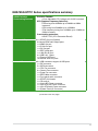
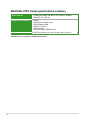
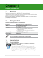
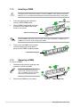
Download ASUS M4A785G_HTPCRC Owner's Manual

Transcript
Motherboard
M4A785G HTPC
Series
E4849
First Edition V1
July 2009
Copyright © 2009 ASUSTeK Computer Inc. All Rights Reserved.
No part of this manual, including the products and software described in it, may be reproduced,
transmitted, transcribed, stored in a retrieval system, or translated into any language in any form or by any
means, except documentation kept by the purchaser for backup purposes, without the express written
permission of ASUSTeK Computer Inc. (“ASUS”).
Product warranty or service will not be extended if: (1) the product is repaired, modified or altered, unless
such repair, modification of alteration is authorized in writing by ASUS; or (2) the serial number of the
product is defaced or missing.
ASUS PROVIDES THIS MANUAL “AS IS” WITHOUT WARRANTY OF ANY KIND, EITHER EXPRESS
OR IMPLIED, INCLUDING BUT NOT LIMITED TO THE IMPLIED WARRANTIES OR CONDITIONS OF
MERCHANTABILITY OR FITNESS FOR A PARTICULAR PURPOSE. IN NO EVENT SHALL ASUS, ITS
DIRECTORS, OFFICERS, EMPLOYEES OR AGENTS BE LIABLE FOR ANY INDIRECT, SPECIAL,
INCIDENTAL, OR CONSEQUENTIAL DAMAGES (INCLUDING DAMAGES FOR LOSS OF PROFITS,
LOSS OF BUSINESS, LOSS OF USE OR DATA, INTERRUPTION OF BUSINESS AND THE LIKE),
EVEN IF ASUS HAS BEEN ADVISED OF THE POSSIBILITY OF SUCH DAMAGES ARISING FROM ANY
DEFECT OR ERROR IN THIS MANUAL OR PRODUCT.
SPECIFICATIONS AND INFORMATION CONTAINED IN THIS MANUAL ARE FURNISHED FOR
INFORMATIONAL USE ONLY, AND ARE SUBJECT TO CHANGE AT ANY TIME WITHOUT NOTICE,
AND SHOULD NOT BE CONSTRUED AS A COMMITMENT BY ASUS. ASUS ASSUMES NO
RESPONSIBILITY OR LIABILITY FOR ANY ERRORS OR INACCURACIES THAT MAY APPEAR IN THIS
MANUAL, INCLUDING THE PRODUCTS AND SOFTWARE DESCRIBED IN IT.
Products and corporate names appearing in this manual may or may not be registered trademarks or
copyrights of their respective companies, and are used only for identification or explanation and to the
owners’ benefit, without intent to infringe.
ii
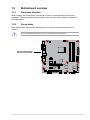
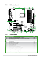
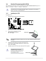
Contents
Contents....................................................................................................... iii
Notices.......................................................................................................... vi
Safety information...................................................................................... vii
About this guide........................................................................................ viii
M4A785G HTPC Series specifications summary...................................... ix
Chapter 1
Product introduction
1.1
Welcome!....................................................................................... 1-1
1.3
Special features............................................................................. 1-1
1.2
1.4
1.5
Package contents.......................................................................... 1-1
1.3.1
1.3.2
1.7
Motherboard overview.................................................................. 1-5
1.5.1
Placement direction......................................................... 1-5
1.5.3
Motherboard layout.......................................................... 1-6
1.5.4
1.6.1
1.6.2
Installing the CPU............................................................ 1-7
Installing the heatsink and fan......................................... 1-8
1.7.1
Overview........................................................................ 1-10
1.7.3
Installing a DIMM........................................................... 1-18
1.7.4
Memory configurations................................................... 1-10
Removing a DIMM......................................................... 1-18
Expansion slots........................................................................... 1-19
1.8.1
Installing an expansion card.......................................... 1-19
1.8.3
PCI slot.......................................................................... 1-19
1.8.4
1.10
Layout contents................................................................ 1-6
System memory.......................................................................... 1-10
1.8.2
1.9
Screw holes..................................................................... 1-5
Central Processing Unit (CPU).................................................... 1-7
1.7.2
1.8
Innovative ASUS features................................................ 1-2
Before you proceed...................................................................... 1-4
1.5.2
1.6
Product highlights............................................................ 1-1
1.8.5
Configuring an expansion card...................................... 1-19
PCI Express x1 slots...................................................... 1-19
PCI Express 2.0 x16 slot................................................ 1-19
Jumpers....................................................................................... 1-20
Connectors.................................................................................. 1-21
1.10.1
1.10.2
Rear panel connectors................................................... 1-21
Internal connectors........................................................ 1-25
iii
Contents
1.11
Software support......................................................................... 1-34
1.11.1
Installing an operating system....................................... 1-34
1.11.3
ASUS Home Theater Gate............................................ 1-35
1.11.2
Chapter 2
2.1
2.1.1
ASUS Update utility......................................................... 2-1
2.1.3
ASUS CrashFree BIOS 3 utility....................................... 2-3
2.2.1
BIOS menu screen........................................................... 2-4
2.2.3
Navigation keys................................................................ 2-5
2.2.4
2.2.5
2.2.6
2.2.7
2.2.8
2.2.9
Menu items...................................................................... 2-5
Submenu items................................................................ 2-5
Configuration fields.......................................................... 2-5
General help.................................................................... 2-5
Pop-up window................................................................ 2-5
Scroll bar.......................................................................... 2-5
2.3.1
System Time [xx:xx:xx].................................................... 2-6
2.3.3
Language [English].......................................................... 2-6
2.3.4
2.3.5
2.3.6
2.3.7
System Date [Day xx/xx/xxxx].......................................... 2-6
Primary IDE Master/Slave................................................ 2-6
SATA 1–5/ESATA ............................................................ 2-7
Storage Configuration...................................................... 2-8
System Information.......................................................... 2-8
Ai Tweaker menu........................................................................... 2-9
2.4.1
Ai Overclock Tuner [Auto]................................................ 2-9
2.4.3
DRAM Frequency [Auto].................................................. 2-9
2.4.2
2.4.4
2.4.5
2.4.6
2.4.7
iv
Menu bar.......................................................................... 2-4
Main menu..................................................................................... 2-6
2.3.2
2.4
ASUS EZ Flash 2 utility.................................................... 2-2
BIOS setup program..................................................................... 2-3
2.2.2
2.3
BIOS information
Managing and updating your BIOS............................................. 2-1
2.1.2
2.2
Support DVD information............................................... 1-34
CPU Ratio [Auto].............................................................. 2-9
CPU/NB Frequency [Auto]............................................. 2-10
HT Link Frequency [Auto].............................................. 2-10
Memory Configuration.................................................... 2-10
DRAM Timing Configuration.......................................... 2-10
Contents
2.4.8
CPU Voltage [Auto]........................................................ 2-12
2.4.10
DRAM Voltage [Auto]..................................................... 2-12
2.4.9
2.4.11
2.4.12
2.4.13
2.5
2.4.14
PCIE Spread Spectrum [Auto]....................................... 2-12
2.5.3
Onboard Devices Configuration..................................... 2-15
2.5.5
Chipset........................................................................... 2-14
USB Configuration......................................................... 2-15
PCIPnP.......................................................................... 2-16
Power menu................................................................................. 2-16
2.6.1
Suspend Mode [Auto].................................................... 2-17
2.6.3
ACPI APIC support [Enabled]........................................ 2-17
2.6.4
2.6.5
2.6.6
2.6.7
ACPI 2.0 Support [Disabled].......................................... 2-17
Chassis LED [On].......................................................... 2-17
EuP Ready [Disabled].................................................... 2-17
APM Configuration......................................................... 2-17
Hardware Monitor.......................................................... 2-18
Boot menu................................................................................... 2-19
2.7.1
Boot Device Priority....................................................... 2-19
2.7.3
Security.......................................................................... 2-20
2.7.2
Boot Settings Configuration........................................... 2-19
Tools menu.................................................................................. 2-21
2.8.1
ASUS EZ Flash 2........................................................... 2-21
2.8.3
AI NET 2........................................................................ 2-21
2.8.2
2.9
CPU Spread Spectrum [Auto]........................................ 2-12
CPU Configuration......................................................... 2-13
2.6.2
2.8
HT/SB Voltage [Auto]..................................................... 2-12
2.5.1
2.5.4
2.7
NB Voltage [Auto]........................................................... 2-12
Advanced menu.......................................................................... 2-13
2.5.2
2.6
CPU/NB Voltage [Auto].................................................. 2-12
Express Gate [Auto]....................................................... 2-21
Exit menu..................................................................................... 2-22
Notices
Federal Communications Commission Statement
This device complies with Part 15 of the FCC Rules. Operation is subject to the following two
conditions:
• This device may not cause harmful interference, and
• This device must accept any interference received including interference that may cause
undesired operation.
This equipment has been tested and found to comply with the limits for a Class B digital
device, pursuant to Part 15 of the FCC Rules. These limits are designed to provide
reasonable protection against harmful interference in a residential installation. This
equipment generates, uses and can radiate radio frequency energy and, if not installed
and used in accordance with manufacturer’s instructions, may cause harmful interference
to radio communications. However, there is no guarantee that interference will not occur
in a particular installation. If this equipment does cause harmful interference to radio or
television reception, which can be determined by turning the equipment off and on, the user
is encouraged to try to correct the interference by one or more of the following measures:
• Reorient or relocate the receiving antenna.
• Increase the separation between the equipment and receiver.
• Connect the equipment to an outlet on a circuit different from that to which the receiver is
connected.
• Consult the dealer or an experienced radio/TV technician for help.
The use of shielded cables for connection of the monitor to the graphics card is required
to assure compliance with FCC regulations. Changes or modifications to this unit not
expressly approved by the party responsible for compliance could void the user’s authority
to operate this equipment.
Canadian Department of Communications Statement
This digital apparatus does not exceed the Class B limits for radio noise emissions from
digital apparatus set out in the Radio Interference Regulations of the Canadian Department
of Communications.
This class B digital apparatus complies with Canadian ICES-003.
REACH
Complying with the REACH (Registration, Evaluation, Authorisation, and Restriction of
Chemicals) regulatory framework, we published the chemical substances in our products at
ASUS REACH website at http://green.asus.com/english/REACH.htm.
DO NOT throw the motherboard in municipal waste. This product has been designed to
enable proper reuse of parts and recycling. This symbol of the crossed out wheeled bin
indicates that the product (electrical and electronic equipment) should not be placed in
municipal waste. Check local regulations for disposal of electronic products.
DO NOT throw the mercury-containing button cell battery in municipal waste. This symbol
of the crossed out wheeled bin indicates that the battery should not be placed in municipal
waste.
vi
Safety information
Electrical safety
•
•
•
•
•
•
•
To prevent electrical shock hazard, disconnect the power cable from the electrical outlet
before relocating the system.
When adding or removing devices to or from the system, ensure that the power cables
for the devices are unplugged before the signal cables are connected. If possible,
disconnect all power cables from the existing system before you add a device.
Before connecting or removing signal cables from the motherboard, ensure that all
power cables are unplugged.
Seek professional assistance before using an adapter or extension cord. These devices
could interrupt the grounding circuit.
Ensure that your power supply is set to the correct voltage in your area. If you are not sure
about the voltage of the electrical outlet you are using, contact your local power company.
If the power supply is broken, do not try to fix it by yourself. Contact a qualified service
technician or your retailer.
The optical S/PDIF is an optional component (may or may not be included in your
motherboard) and is defined as a CLASS 1 LASER PRODUCT.
INVISIBLE LASER RADIATION, AVOID EXPOSURE TO BEAM.
•
•
•
Never dispose of the battery in fire. It could explode and release harmful substances into
the environment.
Never dispose of the battery with your regular household waste. Take it to a hazardous
material collection point.
Never replace the battery with an incorrect battery type.
• RISK OF EXPLOSION IF BATTERY IS REPLACED BY AN INCORRECT TYPE.
• DISPOSE OF USED BATTERIES ACCORDING TO THE ABOVE BATTERY-RELATED
INSTRUCTIONS.
Operation safety
•
•
•
•
Before installing the motherboard and adding devices on it, carefully read all the manuals
that came with the package.
Before using the product, ensure all cables are correctly connected and the power
cables are not damaged. If you detect any damage, contact your dealer immediately.
To avoid short circuits, keep paper clips, screws, and staples away from connectors,
slots, sockets and circuitry.
Avoid dust, humidity, and temperature extremes. Do not place the product in any area
where it may become wet.
This motherboard should only be used in environments with ambient temperatures between
5°C (41°F) and 40°C (104°F).
•
•
Place the product on a stable surface.
If you encounter technical problems with the product, contact a qualified service
technician or your retailer.
vii
About this guide
This user guide contains the information you need when installing and configuring the
motherboard.
How this guide is organized
This guide contains the following parts:
• Chapter 1: Product introduction
This chapter describes the features of the motherboard and the new technology it supports.
This chapter tells how to change system settings through the BIOS Setup menus.
Detailed descriptions of the BIOS parameters are also provided.
•
Chapter 2: BIOS setup
Conventions used in this guide
To ensure that you perform certain tasks properly, take note of the following symbols used
throughout this manual.
DANGER/WARNING: Information to prevent injury to yourself
when trying to complete a task.
CAUTION: Information to prevent damage to the components
when trying to complete a task.
IMPORTANT: Instructions that you MUST follow to complete a
task.
NOTE: Tips and additional information to help you complete a
task.
Where to find more information
Refer to the following sources for additional information and for product and software updates.
1.
ASUS websites
The ASUS website provides updated information on ASUS hardware and software
products. Refer to the ASUS contact information.
2.
Optional documentation
Your product package may include optional documentation, such as warranty flyers,
that may have been added by your dealer. These documents are not part of the
standard package.
Typography
Bold text
Italics
<Key>
<Key1>+<Key2>+<Key3>
viii
Indicates a menu or an item to select.
Used to emphasize a word or a phrase.
Keys enclosed in the less-than and greater-than sign means
that you must press the enclosed key.
Example: <Enter> means that you must press the Enter or
Return key.
If you must press two or more keys simultaneously, the key
names are linked with a plus sign (+).
Example: <Ctrl>+<Alt>+<D>
M4A785G HTPC Series specifications summary
CPU
AMD® AM3/AM2+/AM2 Phenom™ II / Athlon™ II /
Phenom™ / Athlon™ / Sempron™ Processors
AMD® 45nm CPU support
AMD Cool’n’Quiet™ Technology
Chipset
AMD® 785G / SB710
System bus
Up to 5200 MT/s; HyperTransport™ 3.0 interface for
AM3 / AM2+ CPU
2000 / 1600 MT/s for AM2 CPU
Memory
Dual-channel memory architecture
- 4 x 240-pin DIMM sockets support unbufferred
ECC / non-ECC DDR2 1200(O.C)* / 1066* / 800 /
667 MHz memory modules
- Supports up to 16GB system memory
* Due to AMD® CPU limitation, DDR2 1200/1066 are
supported by AM3 / AM2+ CPUs for one DIMM per channel
only. Refer to www.asus.com or this user manual for the
Memory QVL (Qualified Vendors Lists).
** Due to OS limitation, when installing total memory of 4GB
capacity or more, Windows 32-bit operation system may
only recognize less than 3GB. Hence, a total installed
memory of less than 3GB is recommended.
Graphics
Integrated ATI Radeon™ HD 4200 GPU
- Supports HDMI™ Technology with max. resolution up
to 1920 x 1200 (1080P)
- Supports Dual-link DVI with max. resolution up to
2560 x 1600 @ 60Hz
- Supports D-Sub with max. resolution up to
2560 x 1440 @ 75Hz for 16:9 format
- Hybrid CrossFireX™ support
- Dual independent displays support with HDMI / DVI
and D-Sub)
- Supports Microsoft® DirectX 10.1, OpenGL 2.0,
Pixel Shader 4.0
- Hardware Decode Acceleration for H.264, VC-1, and
MPEG-2
- Maximum shared memory of 512MB
Expansion Slots
1 x PCIe 2.0 x16 slot
2 x PCIe x1 slots
1 x PCI 2.2 slot
(continued on the next page)
ix
M4A785G HTPC Series specifications summary
Storage
SB710 Chipset:
- 1 x Ultra DMA 133/100/66 for up to 2 PATA devices
- 5 x SATA 3.0 Gb/s ports with RAID 0, 1 and 10 support
- 1 x External SATA 3.0 Gb/s port
* Due to Window® XP/Vista™ limitation, the RAID array with
the total capacity over 2TB cannot be set as a boot disk. A
RAID array over 2TB can only be set as a data disk only.
LAN
Realtek® 8112L Gigabit LAN controller featuring AI NET 2
High Definition Audio
Absolute Pitch Hi-Fi featuring ENVY HD
- 9.1-channel High Definition Audio
- DTS Surround Sensation UltraPC
(supports Windows® Vista™ and Windows® 7 only)
- Lossless 192khz/24-bit BD audio
- Supports Jack-Detection and Multi-Streaming
- 2-channel gold-plated RCA output at back I/O
- Optical S/PDIF Out port at back I/O
IEEE 1394a
JMicron® JMB381 controller supports 2 x IEEE 1394a ports
USB
10 x USB 2.0 /1.1 ports (6 ports at midboard; 4 ports at back panel)
AI HTPC Unique
Features
ASUS HTPC Features:
- ASUS Absolute Pitch Hi-Fi
- ASUS Home Theater Gate
- ASUS Tranquil Mode (AM3/AM2+ CPUs only)
- DTS Surround Sensation UltraPC (supports Windows® Vista™ and Window® 7 only)
ASUS Express Gate
ASUS Quiet Thermal Solution
- ASUS Fanless Design: Soundwave Heat-sink
ASUS EZ DIY
- ASUS Q-Connector
- ASUS CrashFree BIOS 3
- ASUS EZ Flash 2
Other Features
ASUS MyLogo 2™
(continued on the next page)
M4A785G HTPC Series specifications summary
ASUS Exclusive
Overclocking Features
Precision Tweaker:
- vCore: Adjustable CPU voltage at 0.0125V increment
SFS (Stepless Frequency Selection):
- FSB tuning from 200MHz up to 600MHz at 1MHz
increment
- GPU tuning from 500MHz up to 1500MHz
-PCIe frequency tuning from 100MHz up to 150MHz at
1MHz increment
Overclocking protection:
- ASUS C.P.R. (CPU Parameter Recall)
Rear panel I/O ports
1 x S/PDIF Out port (Optical)
2-channel RCA audio output ports
1 x HDMI Out port
1 x D-Sub Out port
1 x DVI Out port
1 x IEEE 1394a port
1 x LAN (RJ-45) port
4 x USB 2.0/1.1 ports
1 x External SATA port
10-channel audio I/O ports
Internal I/O connectors
3 x USB connectors support 6 USB ports
1 x IDE connector
5 x SATA connectors
1 x CPU Fan connector
2 x Chassis Fan connector
1 x Power Fan connector
1 x IEEE1394a connector
1 x Front panel audio connector
1 x S/PDIF Out Header
1 x CD audio in
1 x 24-pin ATX Power connector
1 x 4-pin ATX 12V Power connector
1 x 4-pin ATX Audio Power connector
1 x System Panel (Q-Connector)
(continued on the next page)
xi
M4A785G HTPC Series specifications summary
BIOS features
16 Mb Flash ROM, AMI BIOS, PnP, DMI 2.0, WfM2.0,
SM BIOS 2.5, ACPI 2.0
Support DVD contents
Drivers
ASUS Home Theater Gate
ASUS Express Gate
ASUS PC Probe II
ASUS Update
Anti-Virus Utility (OEM version)
Form factor
uATX form factor: 9.6 in x 9.6 in (24.4 cm x 24.4 cm)
*Specifications are subject to change without notice.
xii
Chapter 1
Product introduction
1.1
Welcome!
Thank you for buying an ASUS® M4A785G HTPC Series motherboard!
The motherboard delivers a host of new features and latest technologies, making it another
standout in the long line of ASUS quality motherboards!
Before you start installing the motherboard, and hardware devices on it, check the items in
your package with the list below.
1.2
Package contents
Check your motherboard package for the following items.
Motherboard
Cables
Accessories
Application DVD
Documentations
ASUS M4A785G HTPC Series motherboard
1 x Ultra DMA 133/100/66 cable
2 x Serial ATA signal cables
1 x I/O shield
1 x 2 in 1 Q-connector (USB and system panel;
Retail version only)
1 x ASUS Home Theater Gate Remote Controller set
(RC Edition only)
ASUS motherboard support DVD
User manual
If any of the above items is damaged or missing, contact your retailer.
1.3
Special features
1.3.1
Product highlights
AMD® Phenom™ II / Athlon™ II / Sempron™ 100 Series
processors (AM3 CPU)
This motherboard supports AMD® AM3 multi-core processors with
unique L3 cache and delivers better overclocking capabilities with less
power consumption. It features dual-channel DDR2 1200(O.C.)/1066
memory support and accelerates data transfer rate up to 5200MT/s via
HyperTransort™ 3.0 based system bus. This motherboard also supports
AMD® CPUs in the new 45nm manufacturing process.
Chapter 1: Product introduction
1-1
AMD® Phenom™ X4 / Phenom™ X3 / Athlon™ X2 / Athlon™ /
Sempron™ processors (socket AM2+ / AM2)
The motherboard supports AMD® Socket AM2+ multi-core processors.
It features dual-channel DDR2 1200(O.C.)/1066 memory support, data
transfer rate up to 5200MT/s via HyperTransport™ 3.0 based system bus
and AMD® Cool ‘n’ Quiet!™ Technology.
AMD® 785G chipset
The AMD® 785G Northbridge is the latest AMD chipset designed for both
HT1.0 and 5200MT/s HyperTransport™ 3.0 (HT 3.0) interface speed and
external graphics in PCI Express 2.0 standard. It features the integrated
ATI Radeon™ HD 4200 GPU and fully Directx 10.1 compliant.
Dual channel DDR2 1200(O.C.)/1066 support
This motherboard supports DDR2 1200(O.C.)/1066, which provides faster
data transfer rate and more bandwidth to increase memory data transfer
rate and computing efficiency. This enhances system performance in 3D
graphics and other memory demanding applications.
Due to AM3/AM2+ CPU limitation, only one DDR2 1200(O.C.)/1066 is supported per
channel. When four DDR2 1200(O.C.)/1066 DIMMs are installed, all DIMMs run at
800MHz frequency by default for system stability.
AMD® Hybrid CrossFireX Technology
Hybrid CrossFireX Technology is a unique multi-GPU technology
combining the onboard GPU and the discrete graphics card together to
enhance 3D graphics performance.
Visit www.amd.com for the Hybrid CrossfireX selected GPUs.
1.3.2
Innovative ASUS features
ASUS HTPC Features
Absolute Pitch Hi-Fi
You can easily experience home theater enjoyment on your computer with
the revolutionary ASUS Absolute Pitch Hi-Fi technology, which features
ENVY HD, Absolute Pitch BD192/24, and DTS Surround Sensation
UltraPC. ENVY HD feaures prodigious 9.1 high definition audio and
fine-textured graphic user interface that simply brings the professional
surround acoustic level to your computer. Absolute Pitch BD192/24
delivers 192khz/24bit Hi-Fi BD lossless, extreme fidelity sound to bring
true BD audio technology to your home theater PC. DTS Surround
Sensation UltraPC provides proprietary DTS algorithms to deliver virtual
5.1 surround through just 2 speakers.
1-2
ASUS M4A785G HTPC Series
Independent Audio Power Connector
Power is the key determinant in audio quality, thus, professional AV (Audio
Visual) equipment usually separate power supply for different channels
or analog/digital signals to ensure high sound quality. The ASUS HTPC
series is the first motherboard series to be equipped with the revolutionary
ASUS Absolute Pitch Hi-Fi technology, which utilizes audio components
with an independent power connector. This effectively reduces electronic
noise to ensure purer sound quality.
Gold-plated RCA Connector
The gold-plated RCA stereo audio connectors are compatible with
amplifiers without requiring additional connectors–making it simple to link
PCs to home theater equipment. The gold-plated cover ensures maximum
conductivity and durability of the connector.
For better sound quality, connect a power plug to the 4-pin audio power connector. Refer
to page 1-31 for details.
ASUS Tranquil Mode
The revolutionary ASUS Tranquil Mode effectively reduces fan speeds,
which lower the CPU power usage while increasing energy efficiency. With
the reduction in fan speeds, the noise also decreases, thus providing you
with the perfect environment to enjoy watching movies or playing music.
ASUS Tranquil Mode is supported by AM3/AM2+ CPU only.
ASUS Home Theater Gate
The ASUS Home Theater Gate, specially designed for the HTPC series,
allows you to easily and quickly launch media applications to enjoy your
music and movies.
For RC Edition: Use the bundled remote controller to launch the ASUS
Home Theater Gate and start media applications.
ASUS Unique Features
ASUS Express Gate
Express Gate is an ASUS exclusive OS, which lets you instantly access
the Internet and key applications before entering Windows®.
The actual boot time depends on the system configuration.
Chapter 1: Product introduction
1-3
1.4
Before you proceed
Take note of the following precautions before you install motherboard components or change
any motherboard settings.
• Unplug the power cord from the wall socket before touching any component.
• Before handling components, use a grounded wrist strap or touch a safely grounded
object or a metal object, such as the power supply case, to avoid damaging them due to
static electricity.
• Hold components by the edges to avoid touching the ICs on them.
• Whenever you uninstall any component, place it on a grounded antistatic pad or in the
bag that came with the component.
• Before you install or remove any component, switch off the ATX power supply and
detach its power cord. Failure to do so may cause severe damage to the motherboard,
peripherals, or components.
Onboard LED
The motherboard comes with a standby power LED that lights up to indicate that the system
is ON, in sleep mode, or in soft-off mode. This is a reminder that you should shut down
the system and unplug the power cable before removing or plugging in any motherboard
component. The illustration below shows the location of the onboard LED.
1-4
ASUS M4A785G HTPC Series
1.5
Motherboard overview
1.5.1
Placement direction
1.5.2
Screw holes
When installing the motherboard, ensure that you place it into the chassis in the correct
orientation. The edge with external ports goes to the rear part of the chassis as indicated in
the image below.
Place eight screws into the holes indicated by circles to secure the motherboard to the
chassis.
Do not overtighten the screws! Doing so can damage the motherboard.
Place this side towards
the rear of the chassis.
Chapter 1: Product introduction
1-5
1-6
1.5.3
Motherboard layout
1.5.4
Layout contents
Connectors/Jumpers/Slots
Page
1.
ATX power connectors (24-pin EATXPWR, 4-pin ATX12V)
1-26
2.
CPU, Chassis and Power Fan connectors (4-pin CPU_FAN, 4-pin CHA_FAN1,
3-pin CHA_FAN2, 3-pin PWR_FAN)
1-25
3.
CPU socket AM2+/AM2
1-7
4.
DDR2 DIMM slots
1-10
5.
Serial ATA connectors (7-pin SATA1-5)
1-28
6.
IDE connector (40-1 pin PRI_IDE)
1-27
7.
Onboard LED (SB_PWR)
1-4
8.
Clear RTC RAM (CLRTC)
1-20
9.
System panel connector (10-1 pin PANEL)
1-29
10.
USB connectors (10-1 pin USB56, USB78, USB910)
1-30
11.
IEEE 1394a port connector (10-1 pin IE1394_2)
1-32
12.
Audio power connector (4-pin AUDIO_PWR)
1-31
13.
Optical drive audio in connector (4-pin CD)
1-30
14.
Front panel audio connector (10-1 pin AAFP)
1-32
15.
Digital audio connector (4-1 pin SPDIF_OUT)
1-31
ASUS M4A785G HTPC Series
1.6
Central Processing Unit (CPU)
The motherboard comes with a CPU socket designed for AMD® AM3/AM2+/AM2 Phenom™ II /
Athlon™ II / Phenom™ / Athlon™ / Sempron™ processors.
The CPU socket is not compatible with AMD® Opteron™ processors. Do not install an
Opteron™ processor on this motherboard.
1.6.1
Installing the CPU
To install a CPU:
1.
Locate the CPU socket on the motherboard.
2.
Press the lever sideways to unlock
the socket, then lift it up to a
90°–100° angle.
Socket lever
Ensure that the socket lever is lifted up to 90°–100° angle, otherwise the CPU will not fit in
completely.
3.
Position the CPU above the socket such that the CPU
corner with the gold triangle matches the socket corner
with a small triangle.
4.
Carefully insert the CPU into the socket until it fits in place.
The CPU fits only in one correct
orientation. DO NOT force the CPU into
the socket to prevent bending the pins
and damaging the CPU!
Small triangle
Gold triangle
Chapter 1: Product introduction
1-7
5.
When the CPU is in place, push down the socket
lever to secure the CPU. The lever clicks on the side
tab to indicate that it is locked.
6.
Install a CPU heatsink and fan following the
instructions that came with the heatsink package.
You can also refer to section 1.6.2 Installing the
heatsink and fan for instructions.
7.
Connect the CPU fan cable to the CPU_FAN
connector on the motherboard.
Do not forget to connect the CPU
fan connector! Hardware monitoring
errors can occur if you fail to plug this
connector.
1.6.2
Installing the heatsink and fan
Ensure that you use only AMD-certified heatsink and fan assembly.
To install the CPU heatsink and fan:
1.
Place the heatsink on top of the installed CPU, making sure that the heatsink fits
properly on the retention module base.
• The retention module base is already installed on the motherboard upon purchase.
• You do not have to remove the retention module base when installing the CPU or
installing other motherboard components.
• If you purchased a separate CPU heatsink and fan assembly, ensure that a Thermal
Interface Material is properly applied to the CPU heatsink or CPU before you install the
heatsink and fan assembly.
CPU Fan
CPU Heatsink
Retention bracket
Retention Module Base
Retention bracket lock
1-8
ASUS M4A785G HTPC Series
Your boxed CPU heatsink and fan assembly should come with installation instructions for
the CPU, heatsink, and the retention mechanism. If the instructions in this section do not
match the CPU documentation, follow the latter.
2.
Attach one end of the retention bracket to the retention module base.
1
2
3
3.
4
5
Align the other end of the retention bracket to the retention module base. A clicking
sound denotes that the retention bracket is in place.
Ensure that the fan and heatsink assembly perfectly fits the retention mechanism module
base, otherwise you cannot snap the retention bracket in place.
4.
Push down the retention bracket lock on the retention mechanism to secure the
heatsink and fan to the module base.
5.
When the fan and heatsink assembly is in place, connect the CPU fan cable to the
connector on the motherboard labeled CPU_FAN.
Do not forget to connect the CPU fan connector! Hardware monitoring errors can occur if
you fail to plug this connector.
Chapter 1: Product introduction
1-9
1.7
System memory
1.7.1
Overview
The motherboard comes with four Double Data Rate 2 (DDR2) Dual Inline Memory Modules
(DIMM) sockets. A DDR2 module has the same physical dimensions as a DDR DIMM but
has a 240-pin footprint compared to the 184-pin DDR DIMM. DDR2 DIMMs are notched
differently to prevent installation on a DDR DIMM socket. The figure illustrates the location of
the DDR2 DIMM sockets:
1.7.2
Channel
Sockets
Channel A
DIMM_A1 and DIMM_A2
Channel B
DIMM_B1 and DIMM_B2
Memory configurations
You may install 512MB, 1GB, 2GB and 4GB unbuffered ECC/non-ECC DDR2 DIMMs into the
DIMM sockets.
• You may install varying memory sizes in Channel A and Channel B. The system maps
the total size of the lower-sized channel for the dual-channel configuration. Any excess
memory from the higher-sized channel is then mapped for single-channel operation.
• Always install DIMMs with the same CAS latency. For optimum compatibility, we
recommend that you obtain memory modules from the same vendor.
• Due to the memory address limitation on 32-bit Windows OS, when you install 4GB
or more memory on the motherboard, the actual usable memory for the OS can be
about 3GB or less. For effective use of memory, we recommend that you install a 64-bit
Windows OS when having 4GB or more memory installed on the motherboard.
• This motherboard does not support DIMMs made up of 256 Mb chips or less. (Memory
chip capacity counts in Megabit, 8 Megabit/Mb=1 Megabyte/MB.)
• Due to AM3/AM2+ CPU limitation, only one DDR2 1200(O.C.)/1066 DIMM is supported
per channel. When four DDR2 1200(O.C.)/1066 DIMMs are installed, all DIMMs run at
800Mhz frequency by default for system stability.
• The default memory operation frequency is dependent on its SPD. Under the default
state, some memory modules for overclocking may operate at a lower frequency than
the vendor-marked value.
• For system stability, use a more efficient memory cooling system to support a full
memory load (4 DIMMs) or overclocking condition.
1-10
ASUS M4A785G HTPC Series
M4A785G HTPC Series Motherboard Qualified Vendors Lists (QVL)
DDR2-1066MHz capability (with AM3 CPU)
SS/ Chip
DS Brand
Timing
Dimm(Bios)
2048MB(Kit of 2) DS N/A
Heat-Sink Package
5-5-5-15
4096MB(Kit of 2) DS N/A
Heat-Sink Package
Heat-Sink Package
5-5-5-15
5-5-5-15
4096MB(Kit of 2) DS N/A
Heat-Sink Package
5-5-5-15
2.1
•
5-5-5-15
1066-7-7-7-24
5-5-5-15
5-5-5-15
5-5-5-15
5-5-5-15
5-5-5-15
5-5-5-15
5-5-5-15
5-5-5-15
5-5-5-15
7
7-7-7-12
1066-6-6-6-24
2.0
•
•
2.0-2.1 •
2.0-2.1
2.2-2.4 •
2.2-2.4 •
2.2-2.4 •
2.2-2.4
2.2-2.4
2.2-2.4 •
2.2-2.4
•
•
•
•
•
2.2
•
2.2
2.2
1.8
2.2
•
•
•
•
2.10
•
2.2
•
•
•
•
•
•
•
•
2.0-2.1 •
2
•
•
•
•
Part No.
Size
Apacer
CRUCIAL
Crucial
G.SKILL
G.SKILL
GEIL
GEIL
GEIL
GEIL
GEIL
GEIL
GEIL
Hynix
Hynix
KINGMAX
KINGMAX
KINGMAX
KINGSTON
KINGSTON
KINGSTON
KINGSTON
KINGSTON
MICRON
MICRON
OCZ
OCZ
OCZ
SAMSUNG
Transcend
Transcend
BUFFALO
BoxP/N:CH.02GAF.C0KK2
(78.0AG9S.9KF)
78.AAGBD.9LZ
BoxP/N:CH.04GAF.F0KK2
(78.AAGAL.9KF)
BoxP/N:TWIN2X4096-8500C5DF
(CM2X2048-8500C5D)(EPP)
BL12864AA106A.8FE5(EPP)
CT25664AA1067.16FE1
F2-8500CL5S-1GBPK
F2-8500CL5D-2GBPK
GB22GB8500C5DC
GE22GB1066C5DC
GE24GB1066C5QC
GB24GB8500C5DC
GE24GB1066C5DC
GX24GB8500C5UDC
GB24GB8500C5QC
HYMP564U64FP8-G7
HYMP 512U64FP8-G7
KLED48F-B8KU6-NGES
KLED48F-A8KI5-EPA
KLEE88F-B8KU6-NNAS
KHX8500D2K2/1GN(EPP)
KHX8500D2/1G
KHX8500D2K2/2GN(EPP)
KVR1066D2N7/1G
KHX8500D2K2/2G
MT8HTF12864AY-1GAE1
MT16HTF25664AY-1GAE1
OCZ2N10662GK(EPP)
OCZ2N1066SR2GK(EPP)
OCZ2RPR10664GK
M378T2953GZ3-CF8
TX1066QLU-2GK
TX1066QLU-4GK
FSX1066D2C-1G
1024MB
2048MB
1024MB
2048MB(Kit of 2)
2048MB(Kit of 2)
2048MB(Kit of 2)
4096MB(Kitof4)
4096MB(Kit of 2)
4096MB(Kit of 2)
4096MB(Kit of 2)
4096MB(Kitof4)
512MB
1024MB
1024MB
1024MB
2048MB
1024MB(Kit of 2)
1024MB
2048MB(Kit of 2)
1024MB
2048MB(Kit of 2)
1024MB
2048MB
2048MB(Kit of 2)
2048MB(Kit of 2)
4096MB(Kit of 2)
1024MB
2048MB(Kit of 2)
4096MB(Kit of 2)
1024MB
SS
DS
DS
DS
SS
SS
SS
DS
DS
DS
DS
SS
DS
SS
DS
DS
SS
SS
SS
DS
DS
SS
DS
DS
DS
DS
DS
SS
DS
DS
N/A
MICRON
N/A
N/A
GEIL
N/A
N/A
GEIL
N/A
N/A
GEIL
HYNIX
HYNIX
KINGMAX
KINGMAX
KINGMAX
N/A
N/A
N/A
ELPIDA
N/A
MICRON
MICRON
BUFFALO
Elixir
Kingbox
Mushkin
Mushkin
UMAX
FSX1066D2C-K4G
M2Y2G64TU8HD5B-BD
N/A
996535
996619
D41002GP0-73BNJ1
2048MB
2048MB
1024MB
2048MB(Kit of 2)
4096MB(Kit of 2)
4096MB(Kit of 2)
DS
DS
DS
DS
DS
DS
N/A
Elixir
MICRON
N/A
N/A
N/A
Apacer
Apacer
CORSAIR
Chapter 1: Product introduction
DIMM socket
Voltage support (Optional)
A*
B*
C*
•
Chip NO.
Vendor
Heat-Sink Package
9DE12D9JKH
Heat-Sink Package
Heat-Sink Package
GL2L128M88BA25AB
Heat-Sink Package
Heat-Sink Package
GL2L128M88BA25AB
Heat-Sink Package
Heat-Sink Package
GL2L128M88BA25AB
HY5PS12821FFP-G7
HY5PS12821FFP-G7
KKB8FNUXF-DXX-18A
KKA8FEIBF-HJK-18A
KKB8FNUXF-DXX-18A
Heat-Sink Package
Heat-Sink Package
Heat-Sink Package
E5108AJBG-1J-E
Heat-Sink Package
D9JKH
D9JKH
Heat-Sink Package
N/A
Heat-Sink Package
N/A
Heat-Sink Package
SAMSUNG K4T51083QG
ELPIDA
Heat-Sink Package
N/A
Heat-Sink Package
N/A
Heat-Sink Package
Heat-Sink Package
N2TU16800E-BD
7YDI2
Heat-Sink Package
Heat-Sink Package
Heat-Sink Package
1066-6-6-6-24
800-5-5-5-18
800-5-5-5-18
800-5-5-5-18
1066-5-5-5-15
7
7
5
5
7
5
5
5-5-5-15(800-55-5-15)
5-5-5-15
6(1066-6-6-6-24)
5-5-4-12
5-5-5-15
5(800-5-5-5-15)
•
1.8
•
•
•
•
•
•
•
•
•
•
•
•
•
•
•
•
•
•
•
•
•
•
•
•
•
•
•
•
•
•
•
•
•
•
•
•
•
•
•
•
1-11
DDR2-1066MHz capability (with AM2+ CPU)
Timing
Dimm(Bios)
4096MB(Kit of 2) DS N/A
Heat-Sink Package
5-5-5-15
4096MB(Kit of 2) DS N/A
Heat-Sink Package
5-5-5-15
4096MB(Kit of 2) DS N/A
Heat-Sink Package
5-5-5-15
2.1
5-5-5-15
1066-7-7-7-24
5-5-5-15
5-5-5-15
5-5-5-15
5-5-5-15
5-5-5-15
5-5-5-15
5-5-5-15
5-5-5-15
5-5-5-15
5-5-5-15
7
7-7-7-12
1066-6-6-6-24
2.0
Part No.
Size
Apacer
78.AAGBD.9LZ
BoxP/N:CH.04GAF.F0KK2
(78.AAGAL.9KF)
BoxP/N:TWIN2X4096-8500C5DF
(CM2X2048-8500C5D)(EPP)
BL12864AA106A.8FE5(EPP)
CT25664AA1067.16FE1
F2-8500CL5S-1GBPK
F2-8500CL5D-2GBPK
F2-8500CL5D-4GBPK
GB22GB8500C5DC
GE22GB1066C5DC
GE24GB1066C5QC
GB24GB8500C5DC
GE24GB1066C5DC
GX24GB8500C5UDC
GB24GB8500C5QC
HYMP564U64FP8-G7
HYMP 512U64FP8-G7
KLED48F-B8KU6-NGES
KLED48F-A8KI5-EPA
KLEE88F-B8KU6-NNAS
KHX8500D2K2/1GN(EPP)
KHX8500D2/1G
KHX8500D2K2/2GN(EPP)
KVR1066D2N7/1G
KHX8500D2K2/2G
MT8HTF12864AY-1GAE1
MT16HTF25664AY-1GAE1
OCZ2N10662GK(EPP)
OCZ2N1066SR2GK(EPP)
OCZ2RPR10664GK
OCZ2RPR10664GK
M378T2953GZ3-CF8
TX1066QLU-2GK
TX1066QLU-4GK
FSX1066D2C-1G
FSX1066D2C-K4G
M2Y2G64TU8HD5B-BD
N/A
996535
996612
996619
Apacer
CORSAIR
CRUCIAL
Crucial
G.SKILL
G.SKILL
G.SKILL
GEIL
GEIL
GEIL
GEIL
GEIL
GEIL
GEIL
Hynix
Hynix
KINGMAX
KINGMAX
KINGMAX
KINGSTON
KINGSTON
KINGSTON
KINGSTON
KINGSTON
MICRON
MICRON
OCZ
OCZ
OCZ
OCZ
SAMSUNG
Transcend
Transcend
BUFFALO
BUFFALO
Elixir
Kingbox
Mushkin
Mushkin
Mushkin
1024MB
2048MB
1024MB
2048MB(Kit of 2)
4096MB(Kit of 2)
2048MB(Kit of 2)
2048MB(Kit of 2)
4096MB(Kitof4)
4096MB(Kit of 2)
4096MB(Kit of 2)
4096MB(Kit of 2)
4096MB(Kitof4)
512MB
1024MB
1024MB
1024MB
2048MB
1024MB(Kit of 2)
1024MB
2048MB(Kit of 2)
1024MB
2048MB(Kit of 2)
1024MB
2048MB
2048MB(Kit of 2)
2048MB(Kit of 2)
4096MB(Kit of 2)
4096MB(Kit of 2)
1024MB
2048MB(Kit of 2)
4096MB(Kit of 2)
1024MB
2048MB
2048MB
1024MB
2048MB(Kit of 2)
2048MB(Kit of 2)
4096MB(Kit of 2)
SS/ Chip
DS Brand
DIMM socket
Voltage support (Optional)
A*
B*
C*
•
Chip NO.
Vendor
SS
DS
DS
DS
DS
SS
SS
SS
DS
DS
DS
DS
SS
DS
SS
DS
DS
SS
SS
SS
DS
DS
SS
DS
DS
DS
DS
DS
DS
SS
DS
DS
DS
DS
DS
DS
DS
DS
N/A
MICRON
N/A
N/A
N/A
GEIL
N/A
N/A
GEIL
N/A
N/A
GEIL
HYNIX
HYNIX
KINGMAX
KINGMAX
KINGMAX
N/A
N/A
N/A
ELPIDA
N/A
MICRON
MICRON
Heat-Sink Package
9DE12D9JKH
Heat-Sink Package
Heat-Sink Package
Heat-Sink Package
GL2L128M88BA25AB
Heat-Sink Package
Heat-Sink Package
GL2L128M88BA25AB
Heat-Sink Package
Heat-Sink Package
GL2L128M88BA25AB
HY5PS12821FFP-G7
HY5PS12821FFP-G7
KKB8FNUXF-DXX-18A
KKA8FEIBF-HJK-18A
KKB8FNUXF-DXX-18A
Heat-Sink Package
Heat-Sink Package
Heat-Sink Package
E5108AJBG-1J-E
Heat-Sink Package
D9JKH
D9JKH
Heat-Sink Package
N/A
Heat-Sink Package
N/A
Heat-Sink Package
N/A
Heat-Sink Package
SAMSUNG K4T51083QG
ELPIDA
Heat-Sink Package
N/A
Heat-Sink Package
N/A
Heat-Sink Package
N/A
Heat-Sink Package
Elixir
N2TU16800E-BD
MICRON 7YDI2
N/A
Heat-Sink Package
N/A
Heat-Sink Package
N/A
Heat-Sink Package
1066-6-6-6-24
800-5-5-5-18
800-5-5-5-18
800-5-5-5-18
1066-5-5-5-15
7
7
•
2.0-2.1
2.0-2.1
2.0-2.1
2.2-2.4
2.2-2.4
2.2-2.4
2.2-2.4
2.2-2.4
2.2-2.4
2.2-2.4
•
•
•
5
2.10
5
2.2
5-5-5(1066-5-5-5-15) 2.2
7
5
5
5-5-5-15(800-5-5-5-15)
5-5-5-15
6(1066-6-6-6-24)
1.8
5-5-4-12
5-5-5-15
2.1
5-5-5-15
2.0-2.1
•
•
•
•
•
•
•
•
•
•
•
2.2
2.2
2.2
1.8
2.2
•
•
•
•
•
•
•
•
•
•
•
•
•
•
•
•
•
•
•
•
•
•
•
•
•
•
•
•
•
•
•
•
•
•
•
•
•
•
•
•
•
•
•
•
•
•
•
•
•
•
•
•
•
•
•
•
•
•
•
•
•
•
•
•
•
•
•
•
DDR2-800MHz capability (with AM3 CPU)
Vendor
Apacer
Apacer
Apacer
Apacer
Apacer
CORSAIR
Part No.
78.91G9I.9K5
78.01GA0.9K5
78.01GA0.9L5
78.A1GA0.9K4
78.A1GA0.9L4
CM2X1024-6400C4
CORSAIR BoxP/N:TWIN2X4096-6400C4DHX
(CM2X2048-6400C4DHX)Ver1.1
CORSAIR BoxP/N:TWIN2X4096-6400C5
(CM2X2048-6400C5)Ver3.1
CORSAIR BoxP/N:TWIN2X4096-6400C5DHX
(CM2X2048-6400C5DHX)Ver4.1
Crucial
BL12864AA80A.8FE5(EPP)
Crucial
BL25664AA80A.16FE5(EPP)
Crucial
CT25664AA800.16FG
G.SKILL F2-6400CL5D-1GBNQ
G.SKILL F2-6400CL4D-2GBPK
G.SKILL F2-6400CL5D-2GBNQ
G.SKILL F2-6400PHU2-2GBNR
1-12
Size
SS/ Chip
DS Brand
Chip NO.
Timing
Dimm(Bios)
512MB
1024MB
1024MB
2048MB
2048MB
1024MB
SS
SS
SS
DS
DS
DS
AM4B5708JQJS8E
AM4B5808CQJS8E
AM4B5808FEWS8E
AM4B5808CQJS8E
AM4B5808FEWS8E
Heat-Sink Package
5
5
5(800-5-5-5-18)
5
5(800-5-5-5-18)
4
DIMM socket
Voltage support (Optional)
A*
B*
C*
•
•
•
•
•
•
•
•
•
•
•
•
1.9
•
•
•
4096MB(Kit of 2) DS N/A
Heat-Sink Package
4-4-4-12
2.10
•
4096MB(Kit of 2) DS N/A
Heat-Sink Package
5-5-5-18
1.80
•
•
4096MB(Kit of 2) DS N/A
Heat-Sink Package
5-5-5-18
1.80
•
•
1024MB
2048MB
2048MB
1024MB(Kit of 2)
1024MB
1024MB
1024MB
Heat-Sink Package
Heat-Sink Package
8ZC27D9JWB
Heat-Sink Package
Heat-Sink Package
Heat-Sink Package
Heat-Sink Package
4-4-4-12
4-4-4-12
6(6-6-6-18)
5-5-5-15
4
5
5
2.0
2.0
•
•
•
•
•
•
•
•
•
•
•
•
SS
DS
DS
SS
DS
DS
DS
APACER
APACER
Apacer
APACER
Apacer
N/A
N/A
N/A
MICRON
N/A
1.8-2.0
ASUS M4A785G HTPC Series
•
•
•
•
DDR2-800MHz capability (with AM3 CPU) (continued)
SS/ Chip
DS Brand
Chip NO.
4096MB(Kit of 2)
4096MB(Kit of 2)
4096MB(Kit of 2)
8192MB(Kit of 2)
2048MB(Kit of 2)
2048MB(Kit of 2)
2048MB(Kit of 2)
2048MB(Kit of 2)
2048MB(Kit of 2)
2048MB(Kit of 2)
2048MB
2048MB
4096MB(Kit of 2)
4096MB(Kit of 2)
4096MB(Kit of 2)
4096MB(Kit of 2)
4096MB(Kit of 2)
4096MB(Kit of 2)
4096MB(Kitof4)
4096MB(Kitof4)
4096MB(Kitof4)
8192MB(Kitof4)
8192MB(Kitof4)
8192MB(Kitof4)
8192MB(Kitof4)
512MB
1024MB
1024MB
1024MB
2048MB
512MB
512MB
1024MB
1024MB
1024MB
2048MB
2048MB
4096MB
2048MB
512MB
1024MB
1024MB
2048MB
1024MB
1024MB
2048MB(Kit of 2)
4096MB(Kit of 2)
8192MB(Kit of 2)
8192MB(Kit of 2)
1024MB
2048MB
2048MB
512MB
1024MB
1024MB
1024MB
2048MB
2048MB
4096MB
DIMM socket
Voltage support (Optional)
A*
B*
C*
DS N/A
Heat-Sink Package
4
2.0-2.1
•
•
DS N/A
Heat-Sink Package
5
1.8-1.9
•
•
•
DS N/A
Heat-Sink Package
6
1.8-1.9
•
•
DS N/A
Heat-Sink Package
6-6-6-18
1.8
•
•
•
DS GEIL
GL2L64M088BA30EB
4-4-4-12
2.0
•
DS GEIL
GL2L64M088BA30EB
5-5-5-15
1.8
•
•
DS N/A
Heat-Sink Package
4-4-4-12
2.0
•
•
•
DS N/A
Heat-Sink Package
5-5-5-15
1.8
•
•
•
DS N/A
Heat-Sink Package
5-5-5-15
1.8
•
•
•
DS N/A
Heat-Sink Package
4-4-4-12
2.1
•
•
•
DS N/A
Heat-Sink Package
•
•
•
DS N/A
Heat-Sink Package
5-5-5-15
•
•
DS GEIL
GL2L128M88BA25AB
4-4-4-12
2.0
•
•
DS GEIL
GL2L128M88BA25AB
5-5-5-15
1.8
•
•
DS GEIL
GL2L64M088BA30EB
5-5-5-15
1.8
•
•
•
DS N/A
Heat-Sink Package
4-4-4-12
2.0
•
•
•
DS N/A
Heat-Sink Package
5-5-5-15
1.8
•
•
•
DS N/A
Heat-Sink Package
5-5-5-15
1.8
•
•
DS GEIL
GL2L64M088BA30EB
4-4-4-12
2.0
•
•
•
DS N/A
Heat-Sink Package
4-4-4-12
2.0
•
•
DS N/A
Heat-Sink Package
5-5-5-15
1.8
•
•
•
DS GEIL
GL2L128M88BA25AB
4-4-4-12
2.0
•
•
DS GEIL
GL2L128M88BA25AB
5-5-5-15
1.8
•
•
•
DS N/A
Heat-Sink Package
4-4-4-12
2.0
•
•
DS N/A
Heat-Sink Package
5-5-5-15
1.8
•
•
•
SS HYNIX
HY5PS12821CFP-S5
5
1.8
•
•
•
SS HYNIX
HY5PS1G831CFP-S6
6
•
•
DS
HY5PS12821CFP-S5
5
•
•
•
SS KINGMAX KKB8FNUBF
5-5-5-18
•
•
DS KINGMAX KKB8FNUBF
5-5-5-18
•
•
•
SS ELPIDA
E5108AJBG-8E-E
1.8
•
•
•
SS KINGSTON D6408TR7CGL25U
800-6-6-6-18
1.8
•
•
SS KINGSTON D1288TEFCGL25U
800-5-5-5-18
1.8
•
•
•
SS KINGSTON D1288TPFCGL25U
800-5-5-5-15
1.8
•
•
•
DS KINGSTON D6408TR7CGL25U
800-6-6-6-18
1.8
•
•
•
DS N/A
Heat-Sink Package
2.0
•
•
•
DS KINGSTON D1288TEFCGL25U
800-5-5-5-18
1.8
•
•
•
DS ELPIDA
E2108ABSE-8G-E
6(800-6-6-6-18)
1.8
•
•
•
DS MICRON 8ZC27D9JWB
6(800-6-6-6-18)
•
•
•
SS
NT5TU64M8BE-25C
5
•
•
•
DS
NT5TU64M8BE-25C
5
•
•
•
DS NANYA
NT5TU64M8CE-25D
•
•
•
DS NANYA
NT5TU128M8CE-AC
5
•
•
DS N/A
Heat-Sink Package
5
1.8
•
•
•
DS N/A
Heat-Sink Package
5
1.8
•
DS N/A
Heat-Sink Package
3-4-4(800-5-5-5-15) 2.35
•
•
•
DS N/A
Heat-Sink Package
5-4-4
1.8
•
•
•
DS N/A
Heat-Sink Package
5
1.80
•
•
•
DS N/A
Heat-Sink Package
5-6-6(800-5-5-5-15) 1.8
•
•
•
SS PSC
P3R1GE3FGF850MAC19 5(800-5-5-5-18)
•
•
•
DS PSC
A3R1GE3CFF734MAA0E 5
•
•
•
DS PSC
P3R1GE3FGF850MAC19 5(800-5-5-5-18)
•
•
•
SS SAMSUNG K4T51083QG
6
•
•
•
SS SAMSUNG K4T1G084QQ
6
•
•
•
SS SAMSUNG K4T1G084QQ(ECC)
6
•
•
DS SAMSUNG K4T51083QG
6
•
•
•
DS SAMSUNG K4T1G084QQ(ECC)
6
•
•
•
DS SAMSUNG K4T1G084QQ
6
•
•
•
DS SAMSUNG K4T2G084QA-HCF7
6
•
•
•
T800UA12C4
512MB
SS
Heat-Sink Package
•
T800UB1GC4
1024MB
DS
Heat-Sink Package
•
•
•
JM800QLU-1G
TS128MLQ64V8U
JM800QLU-2G
1024MB
1024MB
2048MB
SS Transcend TQ243ECF8
SS ELPIDA
E1108ACBG-8E-E
DS Transcend TQ243PCF8
•
•
•
•
•
•
•
Vendor
Part No.
Size
G.SKILL
G.SKILL
G.SKILL
G.SKILL
GEIL
GEIL
GEIL
GEIL
GEIL
GEIL
GEIL
GEIL
GEIL
GEIL
GEIL
GEIL
GEIL
GEIL
GEIL
GEIL
GEIL
GEIL
GEIL
GEIL
GEIL
Hynix
Hynix
Hynix
KINGMAX
KINGMAX
KINGSTON
KINGSTON
KINGSTON
KINGSTON
KINGSTON
KINGSTON
KINGSTON
KINGSTON
MICRON
NANYA
NANYA
NANYA
NANYA
OCZ
OCZ
OCZ
OCZ
OCZ
OCZ
PSC
PSC
PSC
SAMSUNG
SAMSUNG
SAMSUNG
SAMSUNG
SAMSUNG
SAMSUNG
SAMSUNG
Super
Talent
Super
Talent
Transcend
Transcend
Transcend
F2-6400CL4D-4GBPK
F2-6400CL5D-4GBPQ
F2-6400CL6D-4GBMQ
F2-6400CL6D-8GBMQ
GB22GB6400C4DC
GB22GB6400C5DC
GE22GB800C4DC
GE22GB800C5DC
GX22GB6400DC
GX22GB6400UDC
GX22GB6400C4USC
GX22GB6400LX
GB24GB6400C4DC
GB24GB6400C5DC
GB24GB6400C5QC
GE24GB800C4DC
GE24GB800C5DC
GX24GB6400DC
GB24GB6400C4QC
GE24GB800C4QC
GE24GB800C5QC
GB28GB6400C4QC
GB28GB6400C5QC
GE28GB800C4QC
GE28GB800C5QC
HYMP564U64CP8-S5
HYMP112U64CP8-S6
HYMP 512U64CP8-S5
KLDD48F-B8KU5
KLDE88F-B8KU5
KVR800D2N5/ 512
KVR800D2N6/ 512
KVR800D2N5/1G
KVR800D2N5/1G
KVR800D2N6/1G
KHX6400D2/2G
KVR800D2N5/2G
KVR800D2N6/4G
MT16HTF25664AY-800G1
NT 512T64U88B0BY-25C
NT1GT64U8HB0BY-25C
NT1GT64U8HCOBY-25D
NT2GT64U8HC0BY-AC
OCZ2G8001G
OCZ2T8002GK(EPP)
OCZ2FX800C32GK
OCZ2P8004GK
OCZ2G8008GK
OCZ2VU80016GQ
AL7E8G73F-8E1
AL8E8F73C-8E1
AL8E8G73F-8E1
M378T6553GZS-CF7
M378T2863QZS-CF7
M391T2863QZ3-CF7
M378T2953GZ3-CF7
M378T5663QZ3-CF7
M391T5663QZ3-CF7
M378T5263AZ3-CF7
Chapter 1: Product introduction
Timing
Dimm(Bios)
5
5
5
•
1-13
DDR2-800MHz capability (with AM3 CPU) (continued)
DIMM socket
Voltage support (Optional)
A*
B*
C*
•
•
•
•
•
•
•
•
•
•
•
•
•
•
•
•
•
•
1.8
•
•
•
•
•
•
•
•
•
•
•
•
•
•
•
•
•
•
•
•
•
•
•
•
•
2.2
•
•
•
Vendor
Part No.
Size
SS/ Chip
DS Brand
Chip NO.
Timing
Dimm(Bios)
Transcend
Transcend
Asint
Asint
CENTURY
CENTURY
Elixir
Elixir
Elixir
Kingbox
Kingbox
Kingbox
Mushkin
Oci
Patriot
Patriot
Patriot
Patriot
Silicon
Power
Silicon
Power
UMAX
TS256MLQ64V8U
TS256MLQ72V8U
SLY2128M8-JGE
SLZ2128M8-JGE
28V2H8
28VOH8
M2Y1G64TU88D4B-AC
M2Y1G64TU8HB0B-25C
M2Y2G64TU8HD4B-AC
N/A
N/A
N/A
XP2-6400
04701G16CZ5D2A
PSD2 51280081
PSD21G8002
PSD22GB002
PDC24G6400LLK
2048MB
2048MB
1024MB
2048MB
512MB
1024MB
1024MB
1024MB
2048MB
2048MB
2048MB
2048MB
1024MB
1024MB
512MB
1024MB
2048MB
4096MB(Kit of 2)
DS
DS
SS
DS
SS
DS
SS
DS
DS
DS
DS
DS
SS
DS
SS
DS
DS
DS
E1108ACBG-8E-E
E1108ACBG-8E-E(ECC)
DDRII1208-GE
DDRII1208-GE
HY5PS12821BFP-S5
HY5PS12821BFP-S5
N2TU1G80DE-AC
N2TU 51280BE-25C
N2TU1G80DE-AC
EPD2128082200E-3
D9HNL
EPD2128082200E-3
Heat-Sink Package
64M8PC6400
PM64M8D2BU-25EC
PM64M8D2BU-25PAC
PM128M8D2BU-25KC
Heat-Sink Package
5
5
SP001GBLRU800S02
1024MB
SS S-POWER 10YR9N3
5(5-5-5-15)
•
•
•
SP002GBLRU800S02
2048MB
DS S-POWER 10YR9N3
5(5-5-5-15)
•
•
•
D48002GP1-73BEB
2048MB
DS UMAX
800-5-5-5-15
•
•
ELPIDA
ELPIDA
Asint
Asint
HYNIX
HYNIX
Elixir
Elixir
Elixir
Kingbox
MICRON
KINGBOX
Jnfinity
PATRIOT
PATRIOT
PATRIOT
N/A
U2S24D30TP-8E
5
5
5
800-5-5-5-15
4
5
5
5
4-4-4-12
DDR2-800MHz capability (with AM2+ CPU)
Vendor
Part No.
Size
SS/ Chip
DS Brand
Chip NO.
Timing
Dimm(Bios)
Apacer
Apacer
Apacer
Apacer
Apacer
CORSAIR
78.91G9I.9K5
78.01GA0.9K5
78.01GA0.9L5
78.A1GA0.9K4
78.A1GA0.9L4
CM2X1024-6400C4
BoxP/N:TWIN2X4096-6400C4DHX
(CM2X2048-6400C4DHX)Ver1.1
BoxP/N:TWIN2X4096-6400C5
(CM2X2048-6400C5)Ver3.1
BoxP/N:TWIN2X4096-6400C5DHX
(CM2X2048-6400C5DHX)Ver4.1
BL12864AA80A.8FE5(EPP)
BL25664AA80A.16FE5(EPP)
CT25664AA800.16FG
F2-6400CL5D-1GBNQ
F2-6400CL4D-2GBPK
F2-6400CL5D-2GBNQ
F2-6400PHU2-2GBNR
F2-6400CL4D-4GBPK
F2-6400CL5D-4GBPQ
F2-6400CL6D-4GBMQ
F2-6400CL6D-8GBMQ
GB22GB6400C4DC
GB22GB6400C5DC
GE22GB800C4DC
GE22GB800C5DC
GX22GB6400DC
GX22GB6400UDC
GX22GB6400C4USC
GX22GB6400LX
GB24GB6400C4DC
GB24GB6400C5DC
GB24GB6400C5QC
GE24GB800C4DC
GE24GB800C5DC
GX24GB6400DC
GB24GB6400C4QC
GE24GB800C4QC
GE24GB800C5QC
512MB
1024MB
1024MB
2048MB
2048MB
1024MB
SS
SS
SS
DS
DS
DS
APACER
APACER
Apacer
APACER
Apacer
N/A
AM4B5708JQJS8E
AM4B5808CQJS8E
AM4B5808FEWS8E
AM4B5808CQJS8E
AM4B5808FEWS8E
Heat-Sink Package
5
5
5(800-5-5-5-18)
5
5(800-5-5-5-18)
4
DIMM socket
Voltage support (Optional)
A*
B*
C*
•
•
•
•
•
•
•
•
•
•
•
•
1.9
•
•
•
4096MB(Kit of 2) DS
N/A
Heat-Sink Package
4-4-4-12
2.10
•
4096MB(Kit of 2) DS
N/A
Heat-Sink Package
5-5-5-18
1.80
•
•
4096MB(Kit of 2) DS
N/A
Heat-Sink Package
5-5-5-18
1.80
•
•
1024MB
2048MB
2048MB
1024MB(Kit of 2)
1024MB
1024MB
1024MB
4096MB(Kit of 2)
4096MB(Kit of 2)
4096MB(Kit of 2)
8192MB(Kit of 2)
2048MB(Kit of 2)
2048MB(Kit of 2)
2048MB(Kit of 2)
2048MB(Kit of 2)
2048MB(Kit of 2)
2048MB(Kit of 2)
2048MB
2048MB
4096MB(Kit of 2)
4096MB(Kit of 2)
4096MB(Kit of 2)
4096MB(Kit of 2)
4096MB(Kit of 2)
4096MB(Kit of 2)
4096MB(Kitof4)
4096MB(Kitof4)
4096MB(Kitof4)
N/A
N/A
MICRON
N/A
Heat-Sink Package
Heat-Sink Package
8ZC27D9JWB
Heat-Sink Package
Heat-Sink Package
Heat-Sink Package
Heat-Sink Package
Heat-Sink Package
Heat-Sink Package
Heat-Sink Package
Heat-Sink Package
GL2L64M088BA30EB
GL2L64M088BA30EB
Heat-Sink Package
Heat-Sink Package
Heat-Sink Package
Heat-Sink Package
Heat-Sink Package
Heat-Sink Package
GL2L128M88BA25AB
GL2L128M88BA25AB
GL2L64M088BA30EB
Heat-Sink Package
Heat-Sink Package
Heat-Sink Package
GL2L64M088BA30EB
Heat-Sink Package
Heat-Sink Package
4-4-4-12
4-4-4-12
6(6-6-6-18)
5-5-5-15
4
5
5
4
5
6
6-6-6-18
4-4-4-12
5-5-5-15
4-4-4-12
5-5-5-15
5-5-5-15
4-4-4-12
2.0
2.0
•
•
1.8-2.0
•
•
•
•
•
•
•
•
2.0-2.1
1.8-1.9
1.8-1.9
1.8
2.0
1.8
2.0
1.8
1.8
2.1
•
•
•
•
•
•
•
•
•
•
•
•
•
•
•
•
•
•
•
•
•
CORSAIR
CORSAIR
CORSAIR
Crucial
Crucial
Crucial
G.SKILL
G.SKILL
G.SKILL
G.SKILL
G.SKILL
G.SKILL
G.SKILL
G.SKILL
GEIL
GEIL
GEIL
GEIL
GEIL
GEIL
GEIL
GEIL
GEIL
GEIL
GEIL
GEIL
GEIL
GEIL
GEIL
GEIL
GEIL
1-14
SS
DS
DS
SS
DS
DS
DS
DS
DS
DS
DS
DS
DS
DS
DS
DS
DS
DS
DS
DS
DS
DS
DS
DS
DS
DS
DS
DS
N/A
N/A
N/A
N/A
GEIL
GEIL
N/A
N/A
N/A
N/A
N/A
N/A
GEIL
GEIL
GEIL
N/A
N/A
N/A
GEIL
N/A
N/A
5-5-5-15
4-4-4-12
5-5-5-15
5-5-5-15
4-4-4-12
5-5-5-15
5-5-5-15
4-4-4-12
4-4-4-12
5-5-5-15
2.0
1.8
1.8
2.0
1.8
1.8
2.0
2.0
1.8
ASUS M4A785G HTPC Series
•
•
•
•
•
•
•
•
•
•
•
•
•
•
•
•
•
•
•
•
•
•
•
•
•
•
•
•
•
•
•
•
•
•
•
•
•
•
•
•
DDR2-800MHz capability (with AM2+ CPU) (continued)
Vendor
Part No.
Size
SS/ Chip
DS Brand
GEIL
GEIL
GEIL
GEIL
Hynix
Hynix
Hynix
KINGMAX
KINGMAX
KINGSTON
KINGSTON
KINGSTON
KINGSTON
KINGSTON
KINGSTON
KINGSTON
KINGSTON
KINGSTON
MICRON
NANYA
NANYA
NANYA
NANYA
OCZ
OCZ
OCZ
OCZ
OCZ
OCZ
OCZ
PSC
PSC
PSC
SAMSUNG
SAMSUNG
SAMSUNG
SAMSUNG
SAMSUNG
SAMSUNG
SAMSUNG
Super Talent
Super Talent
Transcend
Transcend
Transcend
Transcend
Transcend
Asint
Asint
CENTURY
CENTURY
Elixir
Elixir
Elixir
Kingbox
Kingbox
Kingbox
Mushkin
Oci
Patriot
Patriot
Patriot
Patriot
Silicon
Power
Silicon
Power
UMAX
GB28GB6400C4QC
GB28GB6400C5QC
GE28GB800C4QC
GE28GB800C5QC
HYMP564U64CP8-S5
HYMP112U64CP8-S6
HYMP 512U64CP8-S5
KLDD48F-B8KU5
KLDE88F-B8KU5
KVR800D2N5/ 512
KVR800D2N6/ 512
KVR800D2N5/1G
KVR800D2N5/1G
KVR800D2N6/1G
KHX6400D2LLK2/2GN(EPP)
KHX6400D2/2G
KVR800D2N5/2G
KVR800D2N6/4G
MT16HTF25664AY-800G1
NT 512T64U88B0BY-25C
NT1GT64U8HB0BY-25C
NT1GT64U8HCOBY-25D
NT2GT64U8HC0BY-AC
OCZ2G8001G
OCZ2T8002GK(EPP)
OCZ2FX800C32GK
OCZ2P800R22GK
OCZ2P8004GK
OCZ2G8008GK
OCZ2VU80016GQ
AL7E8G73F-8E1
AL8E8F73C-8E1
AL8E8G73F-8E1
M378T6553GZS-CF7
M378T2863QZS-CF7
M391T2863QZ3-CF7
M378T2953GZ3-CF7
M378T5663QZ3-CF7
M391T5663QZ3-CF7
M378T5263AZ3-CF7
T800UA12C4
T800UB1GC4
JM800QLU-1G
TS128MLQ64V8U
JM800QLU-2G
TS256MLQ64V8U
TS256MLQ72V8U
SLY2128M8-JGE
SLZ2128M8-JGE
28V2H8
28VOH8
M2Y1G64TU88D4B-AC
M2Y1G64TU8HB0B-25C
M2Y2G64TU8HD4B-AC
N/A
N/A
N/A
XP2-6400
04701G16CZ5D2A
PSD2 51280081
PSD21G8002
PSD22GB002
PDC24G6400LLK
8192MB(Kitof4)
8192MB(Kitof4)
8192MB(Kitof4)
8192MB(Kitof4)
512MB
1024MB
1024MB
1024MB
2048MB
512MB
512MB
1024MB
1024MB
1024MB
2048MB(Kit of 2)
2048MB
2048MB
4096MB
2048MB
512MB
1024MB
1024MB
2048MB
1024MB
1024MB
2048MB(Kit of 2)
2048MB(Kit of 2)
4096MB(Kit of 2)
8192MB(Kit of 2)
8192MB(Kit of 2)
1024MB
2048MB
2048MB
512MB
1024MB
1024MB
1024MB
2048MB
2048MB
4096MB
512MB
1024MB
1024MB
1024MB
2048MB
2048MB
2048MB
1024MB
2048MB
512MB
1024MB
1024MB
1024MB
2048MB
2048MB
2048MB
2048MB
1024MB
1024MB
512MB
1024MB
2048MB
4096MB(Kit of 2)
DS
DS
DS
DS
SS
SS
DS
SS
DS
SS
SS
SS
SS
DS
DS
DS
DS
DS
DS
SS
DS
DS
DS
DS
DS
DS
DS
DS
DS
DS
SS
DS
DS
SS
SS
SS
DS
DS
DS
DS
SS
DS
SS
SS
DS
DS
DS
SS
DS
SS
DS
SS
DS
DS
DS
DS
DS
SS
DS
SS
DS
DS
DS
DIMM socket
Voltage support (Optional)
A*
B*
C*
GEIL
GL2L128M88BA25AB
4-4-4-12
2.0
•
•
•
GEIL
GL2L128M88BA25AB
5-5-5-15
1.8
•
•
•
N/A
Heat-Sink Package
4-4-4-12
2.0
•
•
•
N/A
Heat-Sink Package
5-5-5-15
1.8
•
•
•
HYNIX
HY5PS12821CFP-S5
5
1.8
•
•
•
HYNIX
HY5PS1G831CFP-S6
6
•
•
•
HY5PS12821CFP-S5
5
•
•
•
KINGMAX KKB8FNUBF
5-5-5-18
•
•
•
KINGMAX KKB8FNUBF
5-5-5-18
•
•
•
ELPIDA
E5108AJBG-8E-E
1.8
•
•
•
KINGSTON D6408TR7CGL25U
800-6-6-6-18
1.8
•
•
•
KINGSTON D1288TEFCGL25U
800-5-5-5-18
1.8
•
•
KINGSTON D1288TPFCGL25U
800-5-5-5-15
1.8
•
•
KINGSTON D6408TR7CGL25U
800-6-6-6-18
1.8
•
•
N/A
Heat-Sink Package
•
N/A
Heat-Sink Package
2.0
•
•
KINGSTON D1288TEFCGL25U
800-5-5-5-18
1.8
•
•
•
ELPIDA
E2108ABSE-8G-E
6(800-6-6-6-18)
1.8
•
•
•
MICRON
8ZC27D9JWB
6(800-6-6-6-18)
•
•
NT5TU64M8BE-25C
5
•
NT5TU64M8BE-25C
5
•
•
NANYA
NT5TU64M8CE-25D
•
•
NANYA
NT5TU128M8CE-AC
5
•
•
N/A
Heat-Sink Package
5
1.8
•
•
•
N/A
Heat-Sink Package
5
1.8
•
•
•
N/A
Heat-Sink Package
3-4-4(800-5-5-5-15) 2.35
•
•
•
N/A
Heat-Sink Package
4
1.8
•
N/A
Heat-Sink Package
5-4-4
1.8
•
•
•
N/A
Heat-Sink Package
5
1.80
•
•
N/A
Heat-Sink Package
5-6-6(800-5-5-5-15) 1.8
•
•
PSC
P3R1GE3FGF850MAC19 5(800-5-5-5-18)
•
•
PSC
A3R1GE3CFF734MAA0E 5
•
•
•
PSC
P3R1GE3FGF850MAC19 5(800-5-5-5-18)
•
•
•
SAMSUNG K4T51083QG
6
•
SAMSUNG K4T1G084QQ
6
•
•
•
SAMSUNG K4T1G084QQ(ECC)
6
•
•
SAMSUNG K4T51083QG
6
•
•
•
SAMSUNG K4T1G084QQ(ECC)
6
•
•
•
SAMSUNG K4T1G084QQ
6
•
•
•
SAMSUNG K4T2G084QA-HCF7
6
•
•
•
Heat-Sink Package
•
•
Heat-Sink Package
•
•
Transcend TQ243ECF8
5
•
ELPIDA
E1108ACBG-8E-E
5
•
•
Transcend TQ243PCF8
5
•
•
ELPIDA
E1108ACBG-8E-E
5
•
•
ELPIDA
E1108ACBG-8E-E(ECC) 5
•
•
•
Asint
DDRII1208-GE
•
•
•
Asint
DDRII1208-GE
•
•
•
HYNIX
HY5PS12821BFP-S5
•
HYNIX
HY5PS12821BFP-S5
•
•
•
Elixir
N2TU1G80DE-AC
5
•
•
Elixir
N2TU 51280BE-25C
5
1.8
•
•
Elixir
N2TU1G80DE-AC
5
•
•
Kingbox
EPD2128082200E-3
800-5-5-5-15
•
•
•
MICRON
D9HNL
•
•
KINGBOX EPD2128082200E-3
•
•
Heat-Sink Package
4
•
•
•
Jnfinity
64M8PC6400
5
•
•
PATRIOT PM64M8D2BU-25EC
•
•
•
PATRIOT PM64M8D2BU-25PAC 5
•
•
•
PATRIOT PM128M8D2BU-25KC 5
•
•
•
N/A
Heat-Sink Package
4-4-4-12
2.2
•
•
•
SP001GBLRU800S02
1024MB
SS
S-POWER 10YR9N3
5(5-5-5-15)
•
•
•
SP002GBLRU800S02
2048MB
DS
S-POWER 10YR9N3
5(5-5-5-15)
•
•
•
D48002GP1-73BEB
2048MB
DS
UMAX
800-5-5-5-15
•
•
Chapter 1: Product introduction
Chip NO.
U2S24D30TP-8E
Timing
Dimm(Bios)
1-15
DDR2-667MHz capability (with AM3 CPU)
1-16
Vendor
Part No.
Size
SS/ Chip
DS Brand
Apacer
Apacer
Apacer
CORSAIR
CORSAIR
ELPIDA
G.SKILL
G.SKILL
GEIL
GEIL
GEIL
Hynix
Hynix
KINGSTON
KINGSTON
KINGSTON
KINGSTON
KINGSTON
KINGSTON
KINGSTON
NANYA
NANYA
OCZ
SAMSUNG
Super Talent
Super Talent
Asint
Asint
CENTURY
Dynet
Kingbox
Kingbox
Kingbox
MDT
MDT
Patriot
78.91G92.9K5
78.01G9O.9K5
78.A1G9O.9K4
VS 512MB667D2
VS1GB667D2
EBE51UD8AEFA-6E-E
F2-5400PHU2-2GBNT
F2-5300CL5D-4GBMQ
GX21GB5300SX
GX22GB5300LX
GX24GB5300LDC
HYMP112U64CP8-Y5
HYMP 512U64CP8-Y5
KVR667D2N5/ 512
KVR667D2E5/1G
KVR667D2N5/1G
KVR667D2N5/2G
KVR667/D2N5/1G
KVR667D2E5/2G
KVR667D2N5/2G
NT 512T64U88B0BY-3C
NT2GT64U8HB0JY-3C
OCZ26671024V
M378T5263AZ3-CE6
T6UA 512C5
T6UB1GC5
SLX264M8-J6E
SLY2128M8-J6E
26VOH8
DNHM5U 512C8FE-A6
N/A
N/A
N/A
M 512-667-8
M924-667-16A
PSD21G6672
512MB
1024MB
2048MB
512MB
1024MB
512MB
2048MB(Kit of 2)
4096MB(Kit of 2)
1024MB
2048MB
4096MB(Kit of 2)
1024MB
1024MB
512MB
1024MB
1024MB
2048MB
1024MB
2048MB
2048MB
512MB
2048MB
1024MB
4096MB
512MB
1024MB
512MB
1024MB
1024MB
512MB
1024MB
1024MB
1024MB
512MB
1024MB
1024MB
SS
SS
DS
SS
DS
SS
DS
DS
DS
DS
DS
SS
DS
SS
SS
SS
SS
DS
DS
DS
SS
DS
SS
DS
SS
DS
SS
SS
DS
SS
SS
DS
DS
SS
DS
DS
APACER
APACER
APACER
N/A
N/A
ELPIDA
G.Skill
N/A
N/A
N/A
N/A
HYNIX
HYNIX
ELPIDA
ELPIDA
ELPIDA
SAMSUNG
ELPIDA
MICRON
KINGSTON
NANYA
Chip NO.
AM4B5708JQJS7E
AM4B5808CQJS7E
AM4B5808CQJS7E
64M8CFEG
64M8CFEG
E5108AE-6E-E
D264M8GCF
Heat-Sink Package
Heat-Sink Package
Heat-Sink Package
Heat-Sink Package
HY5PS1G831CFP-Y5
HY5PS12821CFP-Y5
E5108AJBG-6E-E
E1108AEBG-8E-E
E1108AEBG-8E-F
K4T1G084QE
E5108AJBG-6E-E
D9HNL(ECC)
D1288TPFCGL25U
NT5TU64M8BE-3C
NT5TU128M8BJ-3C
Ramos
RC1GT084CA0-53EC
SAMSUNG K4T2G084QA-HCE6
N/A
Heat-Sink Package
N/A
Heat-Sink Package
Asint
DDRII6408-6E
Asint
DDRII1208-6E
HYNIX
HY5PS12821CFP-Y5
Dynet
DN5HS82CFE-A6
KINGBOX EPD2128082200E-4
KINGBOX EPD264082200E-4
KINGBOX EPD264082200N-4
MDT
18D 51280D-30648
MDT
18D 51200D-30646
PATRIOT
PM64M8D2BU-3PAC
DIMM socket
Timing
support (Optional)
Lable(Bios) Voltage
A*
B*
C*
5
•
5
•
•
•
5
•
•
N/A
N/A
•
•
•
N/A
N/A
•
•
5
1.7-1.9 •
•
•
5-5-5-15
1.8
•
5-5-5-15
1.8-1.9 •
•
•
•
•
•
5-5-5-15
•
•
5-5-5-15
1.8
•
5
•
•
•
5
1.8
•
•
5(5-5-5-15) 1.8
•
•
•
5(5-5-5-15) 1.8
•
•
5(5-5-5-15) 1.8
•
•
667-5-5-5-15 1.8
•
•
•
667-5-5-5-15 1.8
•
•
•
1.8
•
•
•
667-5-5-5-15 1.8
•
5
1.8
•
•
•
5
•
•
5
1.8
•
•
•
5
•
•
5
1.8
•
•
•
5
1.8
•
•
•
•
•
•
•
•
5
1.85
•
•
•
•
•
1.8
•
•
•
•
4
1.8
•
4
1.8
•
5
•
ASUS M4A785G HTPC Series
DDR2-667MHz capability (with AM2+ CPU)
DIMM socket
Voltage support (Optional)
A*
B*
C*
Apacer
78.91G92.9K5
512MB
SS APACER
AM4B5708JQJS7E
5
•
•
•
Apacer
78.01G9O.9K5
1024MB
SS APACER
AM4B5808CQJS7E
5
•
Apacer
78.A1G9O.9K4
2048MB
DS APACER
AM4B5808CQJS7E
5
•
CORSAIR
VS 512MB667D2
512MB
SS N/A
64M8CFEG
N/A
N/A
•
•
•
CORSAIR
VS1GB667D2
1024MB
DS N/A
64M8CFEG
N/A
N/A
•
ELPIDA
EBE51UD8AEFA-6E-E 512MB
SS ELPIDA
E5108AE-6E-E
5
1.7-1.9
•
•
G.SKILL
F2-5400PHU2-2GBNT 2048MB(Kit of 2) DS G.Skill
D264M8GCF
5-5-5-15
1.8
•
G.SKILL
F2-5300CL5D-4GBMQ 4096MB(Kit of 2) DS N/A
Heat-Sink Package
5-5-5-15
1.8-1.9
•
•
•
GEIL
GX21GB5300SX
1024MB
DS N/A
Heat-Sink Package
•
•
GEIL
GX24GB5300LDC
4096MB(Kit of 2) DS N/A
Heat-Sink Package
5-5-5-15
1.8
•
Hynix
HYMP112U64CP8-Y5 1024MB
SS HYNIX
HY5PS1G831CFP-Y5 5
•
•
•
Hynix
HYMP 512U64CP8-Y5 1024MB
DS HYNIX
HY5PS12821CFP-Y5 5
1.8
•
•
•
KINGSTON KVR667D2N5/ 512
512MB
SS ELPIDA
E5108AJBG-6E-E
5(5-5-5-15)
1.8
•
•
KINGSTON KVR667D2E5/1G
1024MB
SS ELPIDA
E1108AEBG-8E-E
5(5-5-5-15)
1.8
•
•
KINGSTON KVR667D2N5/1G
1024MB
SS ELPIDA
E1108AEBG-8E-F
5(5-5-5-15)
1.8
•
KINGSTON KVR667D2N5/2G
2048MB
SS SAMSUNG K4T1G084QE
667-5-5-5-15 1.8
•
•
•
KINGSTON KVR667/D2N5/1G
1024MB
DS ELPIDA
E5108AJBG-6E-E
667-5-5-5-15 1.8
•
•
KINGSTON KVR667D2E5/2G
2048MB
DS MICRON
D9HNL(ECC)
1.8
•
•
•
KINGSTON KVR667D2N5/2G
2048MB
DS KINGSTON D1288TPFCGL25U
667-5-5-5-15 1.8
•
NANYA
NT 512T64U88B0BY-3C 512MB
SS NANYA
NT5TU64M8BE-3C
5
1.8
•
•
•
NANYA
NT2GT64U8HB0JY-3C 2048MB
DS
NT5TU128M8BJ-3C
5
•
•
OCZ
OCZ26671024V
1024MB
SS Ramos
RC1GT084CA0-53EC 5
1.8
•
•
SAMSUNG M378T5263AZ3-CE6
4096MB
DS SAMSUNG K4T2G084QA-HCE6 5
•
Super Talent T6UA 512C5
512MB
SS N/A
Heat-Sink Package
5
1.8
•
•
Asint
SLX264M8-J6E
512MB
SS Asint
DDRII6408-6E
•
•
•
Asint
SLY2128M8-J6E
1024MB
SS Asint
DDRII1208-6E
•
•
Dynet
DNHM5U 512C8FE-A6 512MB
SS Dynet
DN5HS82CFE-A6
•
Kingbox
N/A
1024MB
SS KINGBOX EPD2128082200E-4
•
•
Kingbox
N/A
1024MB
DS KINGBOX EPD264082200E-4
1.8
•
Kingbox
N/A
1024MB
DS KINGBOX EPD264082200N-4
•
MDT
M 512-667-8
512MB
SS MDT
18D 51280D-30648
4
1.8
•
MDT
M924-667-16A
1024MB
DS MDT
18D 51200D-30646
4
1.8
•
Patriot
PSD21G6672
1024MB
DS PATRIOT
PM64M8D2BU-3PAC 5
•
•
Vendor
Part No.
Size
SS/ Chip
DS Brand
Chip NO.
Timing
Lable(Bios)
Side(s): SS - Single-sided DS - Double-sided
DIMM support:
• A*: Supports one module inserted into either slot as Single-channel memory
configuration.
• B*: Supports two modules inserted into either the yellow slots or the black slots as one
pair of Dual-channel memory configuration.
• C*: Supports four modules inserted into both the yellow slots and the black slots as two
pairs of Dual-channel memory configuration.
Visit the ASUS website for the latest QVL.
Chapter 1: Product introduction
1-17
1.7.3
Installing a DIMM
Unplug the power supply before adding or removing DIMMs or other system components.
Failure to do so can cause severe damage to both the motherboard and the components.
1.
Press the retaining clips outward to
unlock a DDR2 DIMM socket.
2.
Align a DIMM on the socket such that
the notch on the DIMM matches the
break on the socket.
2
DDR2 DIMM notch
1
1
Unlocked retaining clip
A DDR2 DIMM is keyed with a notch so that it fits in only one direction. DO NOT force a
DIMM into a socket to avoid damaging the DIMM.
3.
Firmly insert the DIMM into the socket
until the retaining clips snap back in
place and the DIMM is properly seated.
3
Locked Retaining Clip
1.7.4
Removing a DIMM
To remove a DIMM:
1.
Simultaneously press the retaining clips
outward to unlock the DIMM.
Support the DIMM lightly with your
fingers when pressing the retaining
clips. The DIMM might get damaged
when it flips out with extra force.
2.
1-18
Remove the DIMM from the socket.
2
1
1
DDR2 DIMM notch
ASUS M4A785G HTPC Series
1.8
Expansion slots
In the future, you may need to install expansion cards. The following sub‑sections describe
the slots and the expansion cards that they support.
Unplug the power cord before adding or removing expansion cards. Failure to do so may
cause you physical injury and damage motherboard components.
1.8.1
Installing an expansion card
To install an expansion card:
1.
Before installing the expansion card, read the documentation that came with it and
make the necessary hardware settings for the card.
2.
Remove the system unit cover (if your motherboard is already installed in a chassis).
3.
Remove the bracket opposite the slot that you intend to use. Keep the screw for later
use.
4.
Align the card connector with the slot and press firmly until the card is completely
seated on the slot.
5.
Secure the card to the chassis with the screw you removed earlier.
6.
Replace the system cover.
1.8.2
Configuring an expansion card
After installing the expansion card, configure it by adjusting the software settings.
1.
Turn on the system and change the necessary BIOS settings, if any. See Chapter 2 for
information on BIOS setup.
2.
Assign an IRQ to the card.
3.
Install the software drivers for the expansion card.
When using PCI cards on shared slots, ensure that the drivers support “Share IRQ” or that
the cards do not need IRQ assignments. Otherwise, conflicts will arise between the two PCI
groups, making the system unstable and the card inoperable.
1.8.3
PCI slot
1.8.4
PCI Express x1 slots
1.8.5
PCI Express 2.0 x16 slot
The PCI slot supports cards such as a LAN card, SCSI card, USB card, and other cards that
comply with PCI specifications.
This motherboard supports PCI Express x1 network cards, SCSI cards, and other cards that
comply with the PCI Express specifications.
This motherboard supports a PCI Express 2.0 x16 graphics card that complies with the PCI
Express specifications.
Chapter 1: Product introduction
1-19
1.9
Jumpers
Clear RTC RAM (CLRTC)
This jumper allows you to clear the Real Time Clock (RTC) RAM in CMOS. You can
clear the CMOS memory of date, time, and system setup parameters by erasing
the CMOS RTC RAM data. The onboard button cell battery powers the RAM data in
CMOS, which include system setup information such as system passwords.
To erase the RTC RAM
1. Turn OFF the computer and unplug the power cord.
2. Move the jumper cap from pins 1-2 (default) to pins 2-3. Keep the cap on pins 2-3
for about 5~10 seconds, then move the cap back to pins 1-2.
3. Plug the power cord and turn ON the computer.
4. Hold down the <Del> key during the boot process and enter BIOS setup to re-enter
data.
Except when clearing the RTC RAM, never remove the cap on CLRTC jumper default
position. Removing the cap will cause system boot failure!
• If the steps above do not help, remove the onboard battery and move the jumper again
to clear the CMOS RTC RAM data. After the CMOS clearance, reinstall the battery.
• You do not need to clear the RTC when the system hangs due to overclocking. For
system failure due to overclocking, use the C.P.R. (CPU Parameter Recall) feature. Shut
down and reboot the system so the BIOS can automatically reset parameter settings to
default values.
• Due to the chipset behavior, AC power off is required to enable C.P.R. function. You
must turn off and on the power supply or unplug and plug the power cord before
rebooting the system.
1-20
ASUS M4A785G HTPC Series
1.10
Connectors
1.10.1
Rear panel connectors
1.
Optical S/PDIF Out port. This port connects an external audio output device via an
optical S/PDIF cable.
2.
Video Graphics Adapter (VGA) port This 15-pin port is for a VGA monitor or other
VGA-compatible devices.
3.
USB 2.0 ports 3 and 4. These two 4-pin Universal Serial Bus (USB) ports are
available for connecting USB 2.0 devices.
4.
LAN (RJ-45) port. This port allows Gigabit connection to a Local Area Network (LAN)
through a network hub.
LAN port LED indications
Speed LED
Activity Link LED
Status
Description
OFF
No link
BLINKING
Data activity
Status
Description
OFF
10 Mbps connection
ORANGE
100 Mbps connection
GREEN
1 Gbps connection
ACT/LINK SPEED
LED
LED
LAN port
5.
RCA Out port (right-channel). This port connects a receiver or an amplifier via an
RCA cable.
6. Center/Subwoofer port (orange). This port connects the center/subwoofer speakers.
7.
Rear Speaker Out port (black). This port connects the rear speakers in a 4-channel,
6-channel, 8-channel, or 10-channel audio configuration.
8.
Line In port/Side Speaker Out port (light blue). This port connects the tape, CD,
DVD player, or other audio sources in an 8-channel audio configuration. In an
10-channel audio configuration, this port connects the additional side speakers.
9.
Line Out port (lime). This port connects a headphone or a speaker. In 4-channel,
6-channel, 8-channel, and 10-channel configuration, the function of this port becomes
Front Speaker Out.
10. Microphone port (pink). This port connects a microphone.
Chapter 1: Product introduction
1-21
11.
Side Speaker Out port (gray). This port connects the side speakers in an 8-channel
or 10-channel audio configurations.
Refer to the audio configuration table below for the function of the audio ports in 2, 4, 6, 8,
or 10-channel configuration.
Audio 2, 4, 6, 8, or 10-channel configuration
Port
Headset
2-channel
4-channel
6-channel
8-channel
10-channel
Light Blue
Line In
Line In
Line In
Line In
Additional Side
Speaker Out
Lime
Line Out
Front Speaker Out
Front Speaker Out
Front Speaker Out
Front Speaker Out
Pink
Mic In
Mic In
Mic In
Mic In
Mic In
Orange
–
–
Center/Subwoofer
Center/Subwoofer
Center/Subwoofer
Black
–
Rear Speaker Out
Rear Speaker Ou
Rear Speaker Out
Rear Speaker Out
Gray
–
–
–
Side Speaker Out
Side Speaker Out
12. RCA Out port (left-channel). This port connects a receiver or an amplifier via an RCA
cable.
13. USB 2.0 ports 1 and 2. These two 4-pin Universal Serial Bus (USB) ports are
available for connecting USB 2.0 devices.
• For RC edition, connect the IR receiver to USB 2.0 port 1 or 2 which supports with
power-on function. The power-on function follows the behavior of the system sleep
button which can be customized in Windows® Control Panel.
• To disable the power-on function for USB 2.0 port 1 or 2, set the Power on By USB
Port 1/2 item to [Disabled] in the BIOS. When the Power on By USB Port 1/2 item is
set to [Enabled], connecting/disconnecting the USB devices to/from these two ports will
power on the system. Refer to page 2-17 for details.
14. External SATA port. This port connects an external Serial ATA hard disk drive.
• The external SATA port supports external Serial ATA 3.0 Gb/s devices. Longer cables
support higher power requirements to deliver signal up to two meters away, and enables
improved hot-swap function.
• Before using the External SATA port, ensure to set the OnChip SATA Type in the BIOS
settings to [AHCI] and install the AHCI driver.
DO NOT insert a different connector to this port.
15. IEEE 1394a port. This 6-pin IEEE 1394a port provides high-speed connectivity for
audio/video devices, storage peripherals, PCs, or portable devices.
16. DVI-I Out port. This port is for any DVI-I compatible device and are HDCP compliant,
allowing playback of HD DVD, Blu-Ray and other protected content.
17. HDMI Out port. This port is for a high-definition multimedia interface (HDMI) connector.
1-22
ASUS M4A785G HTPC Series
Dual display table
This table indicates whether the dual display you want to use is supported or not.
Dual display output
Support
DVI + D-Sub
•
HDMI + D-Sub
•
Not support
DVI + HDMI
•
Playback of HD DVD and Blu-Ray Discs
For better playback quality, we suggest that you follow the system requirements in the
suggested list below.
Suggested list
CPU
AMD® Athlon 4400+
DIMM
DDR2 800 (1GB or higher)
BIOS setup
Frame Buffer Size--256MB or higher
Playback software
CyberLink® PowerDVD 7.3
File format
Best resolution
Windows XP
Windows Vista
Non-protected clips
1920 x 1080p
1920 x 1080p
HD-DVD
1920 x 1080p
1280 x 1080p
Blu-Ray
1280 x 1080p
1280 x 1080p
Chapter 1: Product introduction
1-23
Troubleshooting on HDTV overscaling or underscaling:
If your desktop is extending beyond the viewable display area or the desktop or image is not
filling the entire display area while using the onboard HDMI out port and the HDMI cable, you
can resize the desktop appearing on your HDTV screen.
To resize your HDTV desktop:
1.
Install AMD Chipset Driver from the motherboard support DVD.
2.
Right-click the desktop and select ATI CATALYST(R) Control Center.
3.
From the Graphics Settings tree, expand DTV (HDMI™) 1.
4.
Click Scaling Options.
5.
Move the Underscan/Overscan slider to adjust the overall size of the display on the
HDMI™ DTV.
Using this slider increases or decreases any black borders that may be visible around
the outside of the display.
3
4
5
6
6.
To ensure that forcing a custom display mode through the ATI Displays Manager does
not create conflicting resolutions, select the Use the scaling values instead of the
customized settings when the desktop resolution does not match your DFP
resolution check box.
The Scaling Options function of the DTV (HDMI™) 1 item in the ATI CATALYST Control
Center is adjustable only when you are using an HDTV compliance resolution such as 480i,
720i, or 1080i.
1-24
ASUS M4A785G HTPC Series
1.10.2
1.
Internal connectors
CPU, Chassis and Power Fan connectors (4-pin CPU_FAN, 4-pin CHA_FAN1,
3-pin CHA_FAN2, 3-pin PWR_FAN)
The fan connectors support cooling fans of 350mA–740mA (8.88W max.) or a total of
1A–2.22A (26.64W max.) at +12V. Connect the fan cables to the fan connectors on the
motherboard, making sure that the black wire of each cable matches the ground pin of
the connector.
Do not forget to connect the fan cables to the fan connectors. Insufficient air flow inside the
system may damage the motherboard components. These are not jumpers! DO NOT place
jumper caps on the fan connectors.
Only the CPU_FAN and CHA_FAN1–2 connectors support the ASUS Q FAN 2 feature and
the ASUS Tranquil Mode. Refer to page 2-18 for the fan type setting
Chapter 1: Product introduction
1-25
2.
ATX power connectors (24-pin EATXPWR, 4-pin ATX12V)
These connectors are for an ATX power supply. The plugs from the power supply are
designed to fit these connectors in only one orientation. Find the proper orientation and
push down firmly until the connectors completely fit.
• We recommend that you use an ATX 12 V Specification 2.0‑compliant power supply
unit (PSU) with a minimum of 300 W power rating. This PSU type has 24-pin and 4-pin
power plugs.
• If you intend to use a PSU with 20-pin and 4-pin power plugs, ensure that the 20-pin
power plug can provide at least 15 A on +12 V and that the PSU has a minimum power
rating of 300 W. The system may become unstable or may not boot up if the power is
inadequate.
• Do not forget to connect the 4-pin ATX +12 V power plug. Otherwise, the system will not
boot up.
• We recommend that you use a PSU with higher power output when configuring a
system with more power-consuming devices or when you intend to install additional
devices. The system may become unstable or may not boot up if the power is
inadequate.
• If you are uncertain about the minimum power supply requirement for your system,
refer to the Recommended Power Supply Wattage Calculator at http://support.asus.
com/PowerSupplyCalculator/PSCalculator.aspx?SLanguage=en-us for details.
1-26
ASUS M4A785G HTPC Series
3.
IDE connector (40-1 pin PRI_IDE)
The onboard IDE connector is for Ultra DMA 133/100/66 signal cable. There are three
connectors on each Ultra DMA 133 / 100 / 66 signal cable: blue, black, and gray.
Connect the blue connector to the motherboard’s IDE connector, then select one of the
following modes to configure your devices:
Single device
Drive jumper setting
Mode of device(s)
Cable connector
Cable-Select or Master
-
Black
Master
Black
Slave
Gray
Cable-Select
Two devices
Master
Master
Slave
Slave
Black or gray
• Pin 20 on the IDE connector is removed to match the covered hole on the Ultra DMA
cable connector. This prevents incorrect insertion when you connect the IDE cable.
• Use the 80-conductor IDE cable for Ultra DMA 133/100/66 IDE devices.
If any device jumper is set as “Cable-Select”, ensure that all other device jumpers have the
same setting.
Chapter 1: Product introduction
1-27
4.
Serial ATA connectors (7-pin SATA1-5)
These connectors are for the Serial ATA signal cables for Serial ATA 3Gb/s hard disk
and optical disk drives. The Serial ATA 3Gb/s is backward compatible with Serial ATA
1.5Gb/s specification. The data transfer rate of the Serial ATA 3Gb/s is faster than the
standard parallel ATA with 133 MB/s (Ultra DMA133). If you install Serial ATA hard disk
drives, you can create a RAID 0, RAID 1 or RAID 10 configuration through the onboard
SB710 chipset.
Important note on Serial ATA
Install Windows® XP Service Pack 2 or later version before using Serial ATA.
• For detailed instructions on how to configure RAID 0, RAID 1 and RAID 10, refer to the
RAID manual in the support DVD.
• If you intend to create a Serial ATA RAID set using these connectors, set the OnChip
SATA Type item in the BIOS to [RAID]. See page 2-8 for details.
1-28
ASUS M4A785G HTPC Series
5.
System panel connector (10-1 pin PANEL)
This connector supports several chassis-mounted functions.
•
System power LED (2-pin PLED)
•
Hard disk drive activity LED (2-pin IDE_LED)
•
System warning speaker (4-pin SPEAKER)
•
ATX power button/soft-off button (2-pin PWRSR)
•
Reset button (2-pin RESET)
This 2-pin connector is for the system power LED. Connect the chassis power LED
cable to this connector. The system power LED lights up when you turn on the system
power, and blinks when the system is in sleep mode.
This 2-pin connector is for the HDD Activity LED. Connect the HDD Activity LED cable
to this connector. The IDE LED lights up or flashes when data is read from or written to
the HDD.
This 4-pin connector is for the chassis-mounted system warning speaker. The speaker
allows you to hear system beeps and warnings.
This connector is for the system power button. Pressing the power button turns
the system on or puts the system in sleep or soft-off mode depending on the BIOS
settings. Pressing the power switch for more than four seconds while the system is ON
turns the system OFF.
This 2-pin connector is for the chassis-mounted reset button for system reboot without
turning off the system power.
Chapter 1: Product introduction
1-29
6.
USB connectors (10-1 pin USB56, USB78, USB910)
These connectors are for USB 2.0 ports. Connect the USB module cable to any of
these connectors, then install the module to a slot opening at the back of the system
chassis. These USB connectors comply with USB 2.0 specification that supports up to
480 Mbps connection speed.
Never connect a 1394 cable to the USB connectors. Doing so will damage the
motherboard!
The USB 2.0 module is purchased separately.
7.
1-30
Optical drive audio in connector (4-pin CD)
This connector allows you to receive stereo audio input from sound sources such as a
CD-ROM, TV tuner, or MPEG card.
ASUS M4A785G HTPC Series
8.
Audio power connector (4-pin Audio_PWR)
This connector is for a 4-pin power plug from a power supply. Connect a power plug to
this audio power connector for better sound quality.
• We highly recommend that you connect a power plug to this audio power connector
for ensuring effective audio output. When the system detects that no power cable is
plugged in this connector, a reminder will appear during POST. You may turn off the
reminder in the BIOS setup. Refer to page 2-15 for details.
• Do not share the same power cable with other devices to reduce the electronic
interruption.
9.
Digital audio connector (4-1 pin SPDIF_OUT)
This connector is for an additional Sony/Philips Digital Interface (S/PDIF) ports.
The S/PDIF module is purchased separately.
Chapter 1: Product introduction
1-31
10. Front panel audio connector (10-1 pin AAFP)
This connector is for a chassis-mounted front panel audio I/O module that supports
either High Definition Audio or AC`97 audio standard. Connect one end of the front
panel audio I/O module cable to this connector.
• We recommend that you connect a high-definition front panel audio module to this
connector to avail of the motherboard high-definition audio capability.
• If you want to connect a high-definition front panel audio module to this connector,
ensure that the Front Panel Select item in the BIOS is set to [HD]. If you want to
connect an AC’97 front panel audio module to this connector, set the item to [AC97].
See page 2-15 for details.
11.
IEEE 1394a port connector (10-1 pin IE1394_2)
This connector is for an IEEE 1394a port. Connect the IEEE 1394a module cable to this
connector, then install the module to a slot opening at the back of the system chassis.
Never connect a USB cable to the IEEE 1394a connector. Doing so will damage the
motherboard!
The IEEE 1394a module cable is purchased separately.
1-32
ASUS M4A785G HTPC Series
ASUS Q-Connector (system panel)
You can use the ASUS Q-Connector to connect/disconnect chassis front panel cables in a
few steps. Refer to the instructions below to install the ASUS Q-Connector.
1.
Connect the front panel cables to the ASUS
Q-Connector.
Refer to the labels on the Q-Connector to
know the detailed pin definitions, then match
them to the respective front panel cable
labels.
The labels of the front panel cables
may differ from chassis made by
different manufacturers.
IDE_LED+
IDE_LED-
PWR
Ground
Reset
Ground
2.
Install the ASUS Q-Connector to the system
panel connector, making sure the orientation
matches the labels on the motherboard.
3.
The front panel functions are now enabled.
The figure shows the Q-Connector properly
installed on the motherboard.
Chapter 1: Product introduction
IDE_LED
R SW
POWE
RESET
SW
1-33
1.11
Software support
1.11.1
Installing an operating system
This motherboard supports Windows® XP / 64-bit XP / Vista™ Operating Systems (OS).
Always install the latest OS version and corresponding updates to maximize the features of
your hardware.
• Motherboard settings and hardware options vary. Use the setup procedures presented in
this chapter for reference only. Refer to your OS documentation for detailed information.
• Ensure that you install Windows® XP Service Pack 2 or later versions before installing
the drivers for better compatibility and system stability.
1.11.2
Support DVD information
The Support DVD that comes with the motherboard package contains the drivers, software
applications, and utilities that you can install to avail all motherboard features.
• The contents of the Support DVD are subject to change at any time without notice. Visit
the ASUS website at www.asus.com for updates.
• For detailed software instructions, see the Manual menu in the Support DVD or
download the latest software manual from the ASUS website at www.asus.com.
To run the Support DVD
Place the Support DVD to the optical drive. The DVD automatically displays the Drivers menu
if Autorun is enabled in your computer.
The screen on this page is used for reference only.
Click an icon to
display Support DVD/
motherboard information
Click an item to install
If Autorun is NOT enabled in your computer, browse the contents of the Support DVD to
locate the file ASSETUP.EXE from the BIN folder. Double-click the ASSETUP.EXE to run
the DVD.
1-34
ASUS M4A785G HTPC Series
1.11.3
ASUS Home Theater Gate
The ASUS Home Theater Gate, specially designed for the HTPC series, allows you to easily
and quickly launch media applications to enjoy your music and movies. With the bundled
remote controller, you can launch the ASUS Home Theater Gate and start media applications
with just one touch.
Launching Home Theater Gate
1.
Install Home Theater Gate from the motherboard support DVD.
2.
To launch Home Theater Gate ,click Start > All Programs > ASUS > ASUS Home
Theater Gate > ASUS Home Theater Gate 1.xx.xx. The Home Theater Gate main
window appears.
Home Theater Gate main window
Click to minimize the Home Theater Gate window. Click the Home Theater
Gate icon in the Windows® notification area to restore the window
Click to return to the main window
Click to return to the previous page
Click to close the Home
Theater Gate window
Click to switch to the full
screen mode
View photos
Playback videos
Configure the Tranquil Mode,
Media Path Settings, Internet
Radio Settings, and Favorite
Music
Create your
Playback Internet Radio
music playlists
The Internet Radio function is included in the bundled trial version software “mediaU Player
Mercury“. You may use the Top 20, Station Overview, History, Recommendations,
Station Search, and Recording Schedule functions without registering the software and
within the evaluation period.
Chapter 1: Product introduction
1-35
Internet Radio channel setting
Long press the channel number and the station information on the currently playing station
will be saved to that channel number.
Supported type
Resolution
Normal display under 1024 x 600 – 1920 x 1080
Music
mp3, midi, wav, wma and cda
Video
avi, mp4, mpeg, rmvb, wmv, rm, mov, asf, mpg, vob and dat
Photo
bmp, dib, gif, jpg, jpeg, png, tif, tiff
DTS
Video player
Music player
Windows® Vista™ and Window® 7 operating systems (HDMI and analog
out only)
Windows® Media Player, PowerDVD 8 (Cyberlink), WinDVD 9 (Corel/
InterVideo), KMPlayer, Media Player Classic, RealPlayer and Arcsoft
TotalMedia Theatre 3
Windows® Media Player, Winamp, KMPlayer, RealPlayer, iTunes
• Visit the ASUS website at http://support.asus.com/download/download.
aspx?SLanguage=en-us for the latest supported type.
• Due to Window® XP limitation, you have to install the UDF Reader to recognize the
Blu-ray disc.
1-36
ASUS M4A785G HTPC Series
Using the remote controller (RC Edition only)
Use the remote controller to launch the ASUS Home Theater Gate and start media
applications.
Connect the IR receiver to the USB 2.0 port 1 or 2 before using the remote controller.
Power on/off*
Mute
Play/Pause
Fast rewind
Stop
Previous track
Volume up
OK
Scroll left
Fast forward
Next track
Volume down
Scroll up
Scroll right
Scroll down
Main window
Previous page
Switch windows
Full screen
Internet Radio**
Tranquil mode
Music***
DTS on/off
Launch Home Theater
Gate/Minimize Home
Theater Gate window
* This button follows the behavior of the system sleep button. Actual behavior of the system sleep
button can be customized in Windows® Control Panel > Power Options.
** Set up the internet radio channel 1 to 7 before using the Internet Radio.
*** Set the Favorite Music in the Settings or Music mode first.
Chapter 1: Product introduction
1-37
1-38
ASUS M4A785G HTPC Series
Chapter 2
BIOS information
2.1
Managing and updating your BIOS
Save a copy of the original motherboard BIOS file to a USB flash disk in case you need to
restore the BIOS in the future. Copy the original motherboard BIOS using the ASUS Update
utility.
2.1.1
ASUS Update utility
The ASUS Update is a utility that allows you to manage, save, and update the motherboard
BIOS in Windows® environment.
• ASUS Update requires an Internet connection either through a network or an Internet
Service Provider (ISP).
• This utility is available in the support DVD that comes with the motherboard package.
Installing ASUS Update
To install ASUS Update:
1.
Place the support DVD in the optical drive. The Drivers menu appears.
2.
Click the Utilities tab, and then click Install ASUS Update.
3.
Follow the onscreen instructions to complete the installation.
Quit all Windows® applications before you update the BIOS using this utility.
Updating the BIOS
To update the BIOS:
1.
From the Windows® desktop, click Start > Programs > ASUS > ASUSUpdate >
ASUSUpdate to launch the ASUS Update utility.
2.
From the dropdown list, select any of the updating process:
Updating from the Internet
a. Select Update BIOS from the Internet, and then click Next.
b. Select the ASUS FTP site nearest you to avoid network traffic, or click Auto
Select, and then click Next.
c. From the FTP site, select the BIOS version that you wish to download, and then
click Next.
The ASUS Update utility is capable of updating itself through the Internet. Always update
the utility to avail all its features.
Chapter 2: BIOS setup
2-1
Updating from a BIOS file
a. Select Update BIOS from a file, and then click Next.
b. Locate the BIOS file from the Open window, and then click Open.
3.
Follow the onscreen instructions to complete the updating process.
2.1.2
ASUS EZ Flash 2 utility
The ASUS EZ Flash 2 feature allows you to update the BIOS without having to use a
bootable floppy disk or a DOS‑based utility.
Before you start using this utility, download the latest BIOS from the ASUS website
at www.asus.com.
To update the BIOS using EZ Flash 2:
1.
Insert the USB flash disk that contains the latest BIOS file to the USB port, and then
launch EZ Flash 2 in any of these two ways:
•
•
Press <Alt> + <F2> during POST to display the following.
Enter the BIOS setup program. Go to the Tools menu to select EZ Flash 2 and
press <Enter> to enable it.a.
ASUSTek EZ Flash 2 BIOS ROM Utility V3.38
FLASH TYPE: MXIC 25L1605A
Current ROM
BOARD: M4A785G-HTPC
VER: 0213
DATE: 07/20/2009
Update ROM
BOARD: Unknown
VER: Unknown
DATE: Unknown
PATH: A:\
A:
Note
[Enter] Select or Load
[Up/Down/Home/End] Move
2.
[Tab] Switch
[B] Backup
[V] Drive Info
[Esc] Exit
Press <Tab> to switch between drives until the correct BIOS file is found. When
the correct BIOS file is found, EZ Flash 2 performs the BIOS update process and
automatically reboots the system when done.
• This function can support devices such as a USB flash disk with FAT 32/16 format and
single partition only.
• DO NOT shut down or reset the system while updating the BIOS to prevent system boot
failure!
Ensure to load the BIOS default settings to ensure system compatibility and stability. Select
the Load Setup Defaults item under the Exit menu. See section 2.9 Exit Menu for details.
2-2
ASUS M4A785G HTPC Series
2.1.3
ASUS CrashFree BIOS 3 utility
The ASUS CrashFree BIOS 3 utility is an auto recovery tool that allows you to restore the
BIOS file when it fails or gets corrupted during the updating process. You can restore a
corrupted BIOS file using the motherboard support DVD or a USB flash drive that contains
the BIOS file.
The BIOS file in the motherboard support DVD may be older than the BIOS file published
on the ASUS official website. If you want to use the newer BIOS file, download the file at
support.asus.com and save it to a USB flash drive.
Recovering the BIOS
To recover the BIOS:
1.
Turn on the system.
2.
Insert the motherboard support DVD to the optical drive, or the USB flash drive
containing the BIOS file to the USB port.
3.
The utility automatically checks the devices for the BIOS file. When found, the utility
reads the BIOS file and starts flashing the corrupted BIOS file.
4.
Turn off the system after the utility completes the updating process and power on again.
5.
The system requires you to enter BIOS Setup to recover BIOS setting. To ensure
system compatibility and stability, we recommend that you press <F2> to load default
BIOS values.
DO NOT shut down or reset the system while updating the BIOS! Doing so can cause
system boot failure!
2.2
BIOS setup program
This motherboard supports a programmable firmware chip that you can update using the
provided utility described in section 2.1 Managing and updating your BIOS.
Use the BIOS Setup program when you are installing a motherboard, reconfiguring your
system, or prompted to “Run Setup”. This section explains how to configure your system
using this utility.
Even if you are not prompted to use the Setup program, you can change the configuration of
your computer in the future. For example, you can enable the security password feature or
change the power management settings. This requires you to reconfigure your system using
the BIOS Setup program so that the computer can recognize these changes and record them
in the CMOS RAM of the firmware chip.
The firmware chip on the motherboard stores the Setup utility. When you start up the
computer, the system provides you with the opportunity to run this program. Press <Del>
during the Power-On Self-Test (POST) to enter the Setup utility. Otherwise, POST continues
with its test routines.
If you wish to enter Setup after POST, reboot the system by doing any of the following
procedures:
• Restart using the OS standard shut-down procedure.
•
Press <Ctrl>+<Alt>+<Del> simultaneously.
•
Press the power button to turn the system off then back on.
•
Press the reset button on the system chassis.
Chapter 2: BIOS setup
2-3
Using the power button, reset button, or the <Ctrl>+<Alt>+<Del> keys to force reset from
a running operating system can cause damage to your data or system. We recommend to
always shut-down the system properly from the operating system.
The Setup program is designed to make it as easy to use as possible. Being a menu-driven
program, it lets you scroll through the various submenus and make your selections from the
available options using the navigation keys.
• The default BIOS settings for this motherboard apply for most conditions to ensure
optimum performance. If the system becomes unstable after changing any BIOS
settings, load the default settings to ensure system compatibility and stability. Select the
Load Setups Default item under the Exit Menu. See section 2.9 Exit Menu.
• The BIOS setup screens shown in this section are for reference purposes only, and may
not exactly match what you see on your screen.
• Visit the ASUS website at www.asus.com to download the latest BIOS file for this
motherboard.
2.2.1
BIOS menu screen
Menu items
Main
Menu bar
Ai Tweaker
BIOS SETUP UTILITY
Advanced
Power
Boot
System Time
System Date
Language
Configuration fields
General help
Tools
[10:17:30]
[Tue 06/30/2009]
[English]
Primary IDE Master
Primary IDE Slave
SATA1
SATA2
SATA3
SATA4
SATA5
ESATA
Storage Configuration
:[Not
:[Not
:[Not
:[Not
:[Not
:[Not
:[Not
:[Not
Detected]
Detected]
Detected]
Detected]
Detected]
Detected]
Detected]
Detected]
System Information
Exit
Use [ENTER], [TAB]
or [SHIFT-TAB] to
select a field.
Use [+] or [-] to
configure system Time.
←→
↑↓
+Tab
F1
F10
ESC
Select Screen
Select Item
Change Field
Select Field
General Help
Save and Exit
Exit
v02.61 (C)Copyright 1985-2009, American Megatrends, Inc.
Submenu items
2.2.2
Navigation keys
Menu bar
The menu bar on top of the screen has the following main items:
Main
For changing the basic system configuration
Ai Tweaker
For changing the overclocking settings
Power
For changing the advanced power management (APM) configuration
Advanced
Boot Tools
Exit
2-4
For changing the advanced system settings
For changing the system boot configuration
For changing the system tools configuration
For selecting the exit options and loading default settings
ASUS M4A785G HTPC Series
To select an item on the menu bar, press the right or left arrow key on the keyboard until the
desired item is highlighted.
• The BIOS setup screens shown in this chapter are for reference purposes only, and may
not exactly match what you see on your screen.
• Visit the ASUS website at www.asus.com to download the latest BIOS information.
2.2.3
Navigation keys
At the bottom right corner of a menu screen are the navigation keys for that particular menu.
Use the navigation keys to select items in the menu and change the settings.
Some of the navigation keys differ from one screen to another.
2.2.4
Menu items
2.2.5
Submenu items
2.2.6
Configuration fields
2.2.7
General help
2.2.8
Pop-up window
The highlighted item on the menu bar displays the specific items for that menu. For example,
selecting Main shows the Main menu items.
The other items (Advanced, Power, Boot, Tools, and Exit) on the menu bar have their
respective menu items.
A solid triangle before each item on any menu screen means that the item has a submenu. To
display the submenu, select the item and press <Enter>.
These fields show the values for the menu items. If an item is user‑configurable, you can
change the value of the field opposite the item. You cannot select an item that is not userconfigurable.
A configurable field is enclosed in brackets, and is highlighted when selected. To change the
value of a field, select it then press <Enter> to display a list of options. Refer to 2.2.8 Pop-up
window.
At the top right corner of the menu screen is a brief description of the selected item.
Select a menu item then press <Enter> to
display a pop-up window with the configuration
options for that item.
2.2.9
Scroll bar
A scroll bar appears on the right side of a
menu screen when there are items that do not
fit on the screen. Press the <Up> / <Down>
arrow keys or <Page Up> /<Page Down> keys
to display the other items on the screen.
Chapter 2: BIOS setup
Main
BIOS SETUP UTILITY
Advanced
Power
Boot
Ai Tweaker
Suspend Mode
ACPI Version Features
ACPI APIC support
APM Configuration
Hardware Monitor
[Auto]
[Disabled]
[Enabled]
Disabled
Enabled
Tools
Exit
Use [ENTER], [TAB] or
[SHIFT-TAB] to select
a field.
Use [+] or [-] to
configure system Time.
←→
↑↓
+-
Tab
F1
F10
ESC
Select Screen
Select Item
Change Field
Select Field
General Help
Save and Exit
Exit
v02.61 (C)Copyright 1985-2008, American Megatrends, Inc.
Scroll bar
Pop-up window
2-5
2.3
Main menu
When you enter the BIOS Setup program, the Main menu screen appears, giving you an
overview of the basic system information.
Refer to section 2.2.1 BIOS menu screen for information on the menu screen items and
how to navigate through them.
Main
Ai Tweaker
BIOS SETUP UTILITY
Advanced
Power
Boot
System Time
System Date
Language
Primary IDE Master
Primary IDE Slave
SATA1
SATA2
SATA3
SATA4
SATA5
ESATA
Storage Configuration
[10:17:30]
[Tue 06/30/2009]
[English]
:[Not
:[Not
:[Not
:[Not
:[Not
:[Not
:[Not
:[Not
Detected]
Detected]
Detected]
Detected]
Detected]
Detected]
Detected]
Detected]
System Information
Tools
Exit
Use [ENTER], [TAB]
or [SHIFT-TAB] to
select a field.
Use [+] or [-] to
configure system Time.
←→
↑↓
+Tab
F1
F10
ESC
Select Screen
Select Item
Change Field
Select Field
General Help
Save and Exit
Exit
v02.61 (C)Copyright 1985-2008, American Megatrends, Inc.
2.3.1
System Time [xx:xx:xx]
2.3.2
System Date [Day xx/xx/xxxx]
2.3.3
Language [English]
2.3.4
Primary IDE Master/Slave
Allows you to set the system time.
Allows you to set the system date.
Allows you to select the display language for the BIOS setup screen.
Configuration options: [繁體中文] [簡體中文] [日本語] [Français] [Deutsch] [English]
While entering Setup, the BIOS automatically detects the presence of IDE devices. There is
a separate submenu for each IDE device. Select a device item then press <Enter> to display
the IDE device information.
The BIOS automatically detects the values opposite the dimmed items (Device, Vendor,
Size, LBA Mode, Block Mode, PIO Mode, Async DMA, Ultra DMA, and SMART monitoring).
These values are not user-configurable. These items show Not Detected if no IDE device is
installed in the system.
Type [Auto]
Selects the type of IDE drive. Setting to [Auto] allows automatic selection of the appropriate
IDE device type. Select [CDROM] if you are specifically configuring a CD-ROM drive. Select
[ARMD] (ATAPI Removable Media Device) if your device is either a ZIP, LS-120, or MO drive.
Configuration options: [Not Installed] [Auto] [CDROM] [ARMD]
2-6
ASUS M4A785G HTPC Series
LBA/Large Mode [Auto]
Enables or disables the LBA mode. Setting to [Auto] enables the LBA mode if the device
supports this mode, and if the device was not previously formatted with LBA mode disabled.
Configuration options: [Disabled] [Auto]
Block (Multi-Sector Transfer) M [Auto]
Enables or disables data multi-sectors transfers. When set to [Auto], the data transfer from
and to the device occurs multiple sectors at a time if the device supports multi-sector transfer
feature. When set to [Disabled], the data transfer from and to the device occurs one sector at
a time. Configuration options: [Disabled] [Auto]
PIO Mode [Auto]
Selects the PIO mode. Configuration options: [Auto] [0] [1] [2] [3] [4]
DMA Mode [Auto]
Selects the DMA mode. Configuration options: [Auto]
SMART Monitoring [Auto]
Sets the Smart Monitoring, Analysis, and Reporting Technology.
Configuration options: [Auto] [Disabled] [Enabled]
32Bit Data Transfer [Enabled]
Enables or disables 32-bit data transfer. Configuration options: [Disabled] [Enabled]
2.3.5
SATA 1–5/ESATA
While entering Setup, the BIOS automatically detects the presence of Serial ATA devices.
There is a separate submenu for each SATA device. Select a device item then press <Enter>
to display the SATA device information.
The BIOS automatically detects the values opposite the dimmed items (Device, Vendor, Size,
LBA Mode, Block Mode, PIO Mode, Async DMA, Ultra DMA, and SMART monitoring). These
values are not user-configurable. These items show Not Detected if no Serial ATA device is
installed in the system.
Type [Auto]
Selects the type of device installed. Setting to [Auto] allows automatic selection of the
appropriate device type. Select [CDROM] if you are specifically configuring a CD-ROM drive.
Select [ARMD] (ATAPI Removable Media Device) if your device is either a ZIP, LS-120, or
MO drive. Configuration options: [Not Installed] [Auto] [CDROM] [ARMD]
This item appears in SATA5 and ESATA only.
LBA/Large Mode [Auto]
Enables or disables the LBA mode. Setting to [Auto] enables the LBA mode if the device
supports this mode, and if the device was not previously formatted with LBA mode disabled.
Configuration options: [Disabled] [Auto]
Block (Multi-sector Transfer) M [Auto]
Enables or disables data multi-sectors transfers. When set to [Auto], the data transfer from
and to the device occurs multiple sectors at a time if the device supports multi-sector transfer
feature. When set to [Disabled], the data transfer from and to the device occurs one sector at
a time. Configuration options: [Disabled] [Auto]
Chapter 2: BIOS setup
2-7
PIO Mode [Auto]
Selects the PIO mode. Configuration options: [Auto] [0] [1] [2] [3] [4]
DMA Mode [Auto]
Selects the DMA mode. Configuration options: [Auto]
SMART Monitoring [Auto]
Sets the Smart Monitoring, Analysis, and Reporting Technology.
Configuration options: [Auto] [Disabled] [Enabled]
32Bit Data Transfer [Enabled]
Enables or disables 32-bit data transfer. Configuration options: [Disabled] [Enabled]
2.3.6
Storage Configuration
This menu allows you to configure the storage devices.
OnChip SATA Channel [Enabled]
Enables or disables the OnChip SATA Channel.
Configuration options: [Enabled] [Disabled]
The following two (2) items appear only when you set the OnChip SATA Channel item to
[Manual].
SATA Port1 - Port4 [IDE]
Allows you to select the SATA type for SATA port 1–4.
Configuration options: [IDE] [RAID] [AHCI]
SATA Port5 - Port6 [IDE]
Allows you to select the SATA type for SATA port 5/6. The available configuration
options vary depending on the setting of the SATA Port1 - Port4 item.
• If you want the Serial ATA hard disk drives to use the Advanced Host Controller Interface
(AHCI), set this item to [AHCI]. The AHCI allows the onboard storage driver to enable
advanced Serial ATA features that increases storage performance on random workloads
by allowing the drive to internally optimize the order of commands.
• If you want to create a RAID 0, RAID 1, and RAID 10 configuration from the Serial ATA
hard disk drives, set this item to [RAID].
2.3.7
System Information
This menu gives you an overview of the general system specifications. The BIOS
automatically detects the items in this menu.
BIOS Information
Displays the auto-detected BIOS information.
Processor
Displays the auto-detected CPU specification.
System Memory
Displays the auto-detected system memory.
2-8
ASUS M4A785G HTPC Series
2.4
Ai Tweaker menu
The Ai Tweaker menu items allow you to configure overclocking-related items.
Be cautious when changing the settings of the Ai Tweaker menu items. Incorrect field
values can cause the system to malfunction.
The default values of the following items vary depending on the CPU and memory modules
you install on the motherboard.
Main
Ai Tweaker
BIOS SETUP UTILITY
Advanced
Power
Boot
Configure System Frequency/Voltage
Ai Overclock Tuner
[Auto]
CPU Ratio
[Auto]
DRAM Frequency
[Auto]
CPU/NB Frequency
[Auto]
HT Link Frequency
[Auto]
Memory Configuration
DRAM Timing Configuration
******* Please key in numbers directly! *******
CPU Voltage
[Auto]
CPU/NB Voltage
[Auto]
DRAM Voltage
[Auto]
NB Voltage
[Auto]
HT/SB Voltage
[Auto]
***********************************************
CPU Spread Spectrum
[Auto]
PCIE Spread Spectrum
[Auto]
Tools
Exit
Select the target CPU
frequency, and the
relevant parameters
will be auto-adjusted.
←→
↑↓
+F1
F10
ESC
Select Screen
Select Item
Change Field
General Help
Save and Exit
Exit
v02.61 (C)Copyright 1985-2009, American Megatrends, Inc.
2.4.1
Ai Overclock Tuner [Auto]
Allows selection of CPU overclocking options to achieve desired CPU internal frequency.
Configuration options: [Manual] [Auto]
The following two (2) items appear only when you set the Ai Overclock Tuner item to
[Manual].
CPU Bus Frequency [XXX]
Displays the frequency sent by the clock generator to the system bus and PCI bus. Use the
<+> and <-> keys to adjust the FSB frequency. You can also type the desired frequency using
the numeric keypad. The values range from 200 to 600.
PCIE Frequency [XXX]
Use the <+> and <-> keys to adjust the PCIE frequency. You can also type the desired PCIE
frequency using the numeric keypad. The values range from 100 to 150.
2.4.2
CPU Ratio [Auto]
2.4.3
DRAM Frequency [Auto]
Allows you to adjust the ratio between CPU Core Clock and FSB Frequency. Use the <+>
and <-> keys to adjust the value. The valid value ranges vary according to your CPU model.
Allows you to set the DDR2 operating frequency. The configuration options vary with the CPU
Bus Frequency item settings.
Selecting a very high DRAM frequency may cause the system to become unstable! If this
happens, revert to the default setting.
Chapter 2: BIOS setup
2-9
2.4.4
CPU/NB Frequency [Auto]
2.4.5
HT Link Frequency [Auto]
2.4.6
Memory Configuration
Allows you to select the CPU/NB frequency. The configuration options vary with the CPU Bus
Frequency item settings.
Allows you to set the HyperTransport link frequency. The configuration options vary with the
CPU Bus Frequency item settings.
Allows you to change the advanced memory settings.
Bank Interleaving [Auto]
Allows you to enable or disable the bank memory interleaving.
Configuration options: [Disabled] [Auto]
Channel Interleaving [XOR of Address bit]
Allows you to set the channel interleaving mode.
Configuration options: [Disabled] [Address bits 6] [Address bits 12]
[XOR of Address bits [20:16, 6]] [XOR of Address bits [20:16, 9]]
Enable Clock to All DIMMs [Disabled]
Allows you to enable unused clocks to DIMMs even the memory slots are no populated.
Configuration options: [Disabled] [Enabled]
MemClk Tristate C3/ATLVID [Disabled]
Allows you to enable or disable MemClk Tri-Stating during C3 and Alt VID.
Configuration options: [Disabled] [Enabled]
Memory Hole Remapping [Enabled]
Allows you to enable or disable memory remapping around memory hole.
Configuration options: [Disabled] [Enabled]
DCT Unganged Mode [Always]
Allows selection of the unganged DRAM mode.
Configuration options: [Auto] [Always]
Power Down Enable [Disabled]
Allows you to enable or disable the DDR power down mode.
Configuration options: [Disabled] [Enabled]
Power Down Mode [Channel]
Appears only when you enable the Power Down Enable item.
Configuration options: [Channel] [Chip Select]
2.4.7
DRAM Timing Configuration
Allows you to change the advanced DRAM timing settings.
The configuration options for some of the following items vary depending on the DIMMs
you install on the motherboard.
2-10
ASUS M4A785G HTPC Series
DRAM Command Rate [Auto]
Allows selection of the DRAM command rate.
Configuration options: [Auto] [1T] [2T]
DRAM Timing Mode [Auto]
Allows selection of the DRAM Timing Mode.
Configuration options: [Auto] [Manual]
The following sub-items appear only when you set the DRAM Timing Mode item to
[Manual].
DCT0 1st Information: 5-5-5-3(5)-15-20-5-3
TCL [Auto]
Configuration options: [Auto] [3 CLK] [4 CLK] [5 CLK] [6 CLK] [7 CLK DH_Only]
TRCD [Auto]
Configuration options: [Auto] [3 CLK] [4 CLK] [5 CLK] [6 CLK]
TRP [Auto]
Configuration options: [Auto] [3 CLK] [4 CLK] [5 CLK] [6 CLK]
TRTP [Auto]
Configuration options: [Auto] [2-4 CLK] [3-5 CLK]
TRAS [Auto]
Configuration options: [Auto] [5 CLK] [6 CLK] – [17 CLK] [18 CLK]
TRC [Auto]
Configuration options: [Auto] [11 CLK] [12 CLK] – [25 CLK] [26 CLK]
TWR [Auto]
Configuration options: [Auto] [3 CLK] [4 CLK] [5 CLK] [6 CLK]
TRRD [Auto]
Configuration options: [Auto] [2 CLK] [3 CLK] [4 CLK] [5 CLK]
DCT0 2nd Information: 7-105-75
TRWTTO [Auto]
Configuration options: [Auto] [3 CLK] [4 CLK] – [16 CLK] [17 CLK]
TWRRD [Auto]
Configuration options: [Auto] [1 CLK] [2 CLK] [3 CLK] [4 CLK]
TWTR [Auto]
Specifies the write to read delay when accessing the same DIMM.
Configuration options: [Auto] [1 CLK] [2 CLK] [3 CLK]
TWRWR [Auto]
Configuration options: [Auto] [1 CLK] [2 CLK] [3 CLK] [4 CLK]
TRDRD [Auto]
Configuration options: [Auto] [3 CLK] [4 CLK] [5 CLK]
TRFC0 [Auto]
Configuration options: [Auto] [75ns] [105ns] [127.5ns] [195ns] [327.5ns]
TRFC1 [Auto]
Configuration options: [Auto] [75ns] [105ns] [127.5ns] [195ns] [327.5ns]
Chapter 2: BIOS setup
2-11
The following five (5) items are adjusted by typing the desired values using the numeric keypad
and press the <Enter> key. You can also use the <+> and <-> keys to adjust the value. To
restore the default setting, type [auto] using the keyboard and press the <Enter> key.
2.4.8
CPU Voltage [Auto]
2.4.9
CPU/NB Voltage [Auto]
2.4.10
DRAM Voltage [Auto]
2.4.11
NB Voltage [Auto]
2.4.12
HT/SB Voltage [Auto]
2.4.13
CPU Spread Spectrum [Auto]
2.4.14
PCIE Spread Spectrum [Auto]
Allows you to set the CPU VCore voltage.
Allows you to set the CPU/NB voltage.
Allows you to set the DRAM voltage. The values range from 1.80V to 2.50V with a 0.10V interval.
Allows you to set the Northbridge voltage. The values range from 1.10V to 1.20V with a
0.10V interval.
Allows you to set the HyperTransport voltage. The values range from 1.20V to 1.30V with a
0.10V interval.
Set to [Disabled] to enhance FSB overclocking ability or [Enabled] for EMI control.
Configuration options: [Auto] [Disabled] [Enabled]
Set to [Disabled] to enhance PCIE overclocking ability or [Linear Down] for EMI control.
Configuration options: [Auto] [Disabled] [Enabled]
2-12
ASUS M4A785G HTPC Series
2.5
Advanced menu
The Advanced menu items allow you to change the settings for the CPU and other system
devices.
Be cautious when changing the settings of the Advanced menu items. Incorrect field values
can cause the system to malfunction.
Main
Ai Tweaker
BIOS SETUP UTILITY
Advanced
Power
Boot
Tools
CPU Configuration
Chipset
Onboard Devices Configuration
USB Configuration
PCIPnP
Exit
Configure CPU.
←→ Select Screen
↑↓
Select Item
Enter Go to Sub Screen
F1
General Help
F10 Save and Exit
ESC Exit
v02.61 (C)Copyright 1985-2009, American Megatrends, Inc.
2.5.1
CPU Configuration
The items in this menu show the CPU-related information that the BIOS automatically detects.
GART Error Reporting [Disabled]
This option should remain disabled for the normal operation. The driver developer may
enable it for testing purpose. Configuration options: [Disabled] [Enabled]
Microcode Updation [Enabled]
Allows you to enable or disable the microcode updation.
Configuration options: [Disabled] [Enabled]
Secure Virtual Machine Mode [Enabled]
Allows you to enable or disable the AMD Secure Virtual Machine mode (SVM).
Configuration options: [Disabled] [Enabled]
Cool ’n’ Quiet [Enabled]
Enables or disables the AMD Cool’n’Quiet function.
Configuration options: [Disabled] [Enabled]
ACPI SRAT Table [Enabled]
Allows you to enable or disable the building of ACPI SRAT Table.
Configuration options: [Enabled] [Disabled]
CPU Prefetching [Enabled]
Allows you to enable or disable CPU prefetching. Configuration options: [Enabled] [Disabled]
C1E Support [Disabled]
Allows you to enable or disable the Enhanced Halt State support.
Configuration options: [Enabled] [Disabled]
Chapter 2: BIOS setup
2-13
2.5.2
Chipset
The Chipset menu allows you to change the advanced chipset settings. Select an item then
press <Enter> to display the submenu.
ECC Configuration
ECC Mode [Disabled]
Disables or sets the DRAM ECC mode that allows the hardware to report and
correct memory errors. Set this item to [Basic], [Good], or [Max] to allow ECC mode
auto-adjustment. Set this item to [Super] to adjust the DRAM BG Scrub sub-item
manually. You may also adjust all sub-items by setting this item to [User].
Configuration options: [Disabled] [Basic] [Good] [Super] [Max] [User]
DRAM ECC Enable [Disabled]
Set this item to [Enabled] to allow hardware to report and correct memory errors automatically,
maintaining system integrity. Configuration options: [Disabled] [Enabled]
DRAM SCRUB REDIRECT [Disabled]
Enables or disables the DRAM SCRUB REDIRECT feature that allows the system to correct the
DRAM ECC errors immediately when they occur. Configuration options: [Disabled] [Enabled]
4-Bit ECC Mode [Disabled]
Enables or disables the ECC chip kill feature. Configuration options: [Disabled] [Enabled]
DRAM BG Scrub [Disabled]
Disables or sets the DRAM BG Scrub. Configuration options: [Disabled] [40ns] [80ns] [160ns]
[320ns] [640ns] [1.28us] [2.56us] [5.12us] [10.2us] [20.5us] [41.0us] [81.9us] [163.8us] [327.7us]
[655.4us] [1.31ms] [2.62ms] [5.24ms] [10.49ms] [20.97ms] [42.00ms] [84.00ms]
Data Cache BG Scrub [Disabled]
Disables or sets the Data Cache BG Scrub. This item allows the L1 Data Cache RAM to be
corrected when idle. Configuration options: [Disabled] [40ns] [80ns] [160ns] [320ns] [640ns]
[1.28us] [2.56us] [5.12us] [10.2us] [20.5us] [41.0us] [81.9us] [163.8us] [327.7us] [655.4us]
[1.31ms] [2.62ms] [5.24ms] [10.49ms] [20.97ms] [42.00ms] [84.00ms]
L2/L3 Cache BG Scrub [Disabled]
Disables or sets the L2/L3 Cache BG Scrub. This item allows the L2/L3 Data Cache RAM to
be corrected when idle. Configuration options: [Disabled] [40ns] [80ns] [160ns] [320ns] [640ns]
[1.28us] [2.56us] [5.12us] [10.2us] [20.5us] [41.0us] [81.9us] [163.8us] [327.7us] [655.4us]
[1.31ms] [2.62ms] [5.24ms] [10.49ms] [20.97ms] [42.00ms] [84.00ms]
Internal Graphics Configuration
This menu allows you to change the onboard graphics configuration settings. Select an item
then press <Enter> to display the submenu.
UMA Frame Buffer Size [Auto]
Allows you to select the UMA Frame Buffer size. Configuration options: [Auto] [32MB]
[64MB] [128MB] [256MB]
GFX Engine Clock Override [Disabled]
Allows you to enable or disable the GFX Engine Clock Override function.
Configuration options: [Disabled] [Enabled]
Surround View [Auto]
If you set the PCI Express device as the primary display and enable this item, you may
use the internal graphics as the secondary display. Configuration options: [Auto] [Enabled]
[Disabled]
2-14
ASUS M4A785G HTPC Series
FB Location [Above 4G]
Allows you to select the FB Location.
Configuration options: [Below 4G] [Above 4G]
AMD 785G HD Audio [Enabled]
Allows you to disable or enable the AMD 785G HD Audio.
Configuration options: [Disabled] [Enabled]
Primary Display Adapter [PCI-E]
Allows you to select the graphics controller to use as the primary boot device.
Configuration options: [PCI-E] [PCI] [Onboard]
2.5.3
Onboard Devices Configuration
Onboard HD Audio [Enabled]
Allows you to enable or disable the HD Audio controller.
Configuration options: [Disabled] [Enabled]
Front Panel Select [HD]
Allows you to set the front panel audio connector (AAFP) mode to legacy AC’97 or
high-definition audio depending on the audio standard that the front panel audio
module supports. Configuration options: [AC97] [HD]
Audio PWR Reminder [Enabled]
When the system detects that no power cable is plugged in the audio power connector,
a reminder will appear during POST. This item allows you to enable or disable this
function. Configuration options: [Enabled] [Disabled]
Onboard LAN [Enabled]
Allows you to enable or disable the onboard LAN. Configuration options: [Enabled] [Disabled]
Onboard LAN Boot ROM [Disabled]
Allows you to enable or disable the onboard LAN Boot ROM.
Configuration options: [Disabled] [Enabled]
Onboard 1394 [Enabled]
Allows you to enable or disable the onboard 1394 device support.
Configuration options: [Disabled] [Enabled]
2.5.4
USB Configuration
The items in this menu allows you to change the USB-related features. Select an item then
press <Enter> to display the configuration options.
The Module Version and USB Devices Enabled items show the auto-detected values. If
no USB device is detected, the item shows None.
Legacy USB Support [Auto]
Allows you to enable or disable support for USB devices on legacy operating systems
(OS). Setting to Auto allows the system to detect the presence of USB devices at startup.
If detected, the USB controller legacy mode is enabled. If no USB device is detected, the
legacy USB support is disabled. Configuration options: [Disabled] [Enabled] [Auto]
Chapter 2: BIOS setup
2-15
USB 2.0 Controller [Enabled]
Allows you to enable or disable the USB 2.0 controller.
Configuration options: [Enabled] [Disabled]
The following two (2) items appear only when you set the USB 2.0 Controller item to
[Enabled].
USB 2.0 Controller Mode [HiSpeed]
Allows you to configure the USB 2.0 controller in HiSpeed (480 Mbps) or
FullSpeed (12 Mbps). Configuration options: [FullSpeed] [HiSpeed]
BIOS EHCI Hand-Off [Enabled]
Allows you to enable the support for operating systems without an EHCI hand‑off
feature. Configuration options: [Disabled] [Enabled]
2.5.5
PCIPnP
The PCI PnP menu items allow you to change the advanced settings for PCI/PnP devices.
Plug And Play O/S [No]
When set to [No], BIOS configures all the devices in the system. When set to [Yes] and if you
install a Plug and Play operating system, the operating system configures the Plug and Play
devices not required for boot. Configuration options: [No] [Yes]
2.6
Power menu
The Power menu items allow you to change the settings for the Advanced Configuration and
Power Interface (ACPI) and the Advanced Power Management (APM). Select an item then
press <Enter> to display the configuration options.
Main
Ai Tweaker
BIOS SETUP UTILITY
Advanced
Power
Boot
Suspend Mode
ACPI 2.0 Support
ACPI APIC support
Chassis LED
EuP Ready
[Auto]
[Disabled]
[Enabled]
[On]
[Disabled]
Tools
Exit
Select the ACPI state
used for System
Suspend.
APM Configuration
Hardware Monitor
←→
↑↓
+F1
F10
ESC
Select Screen
Select Item
Change Option
General Help
Save and Exit
Exit
v02.61 (C)Copyright 1985-2009, American Megatrends, Inc.
2-16
ASUS M4A785G HTPC Series
2.6.1
Suspend Mode [Auto]
2.6.2
ACPI 2.0 Support [Disabled]
2.6.3
ACPI APIC support [Enabled]
2.6.4
Chassis LED [On]
2.6.5
EuP Ready [Disabled]
2.6.6
APM Configuration
Allows you to select the Advanced Configuration and Power Interface (ACPI) state to be used
for system suspend.
[S1(POS) Only] - E
nables the system to enter the ACPI S1 (Power on Suspend) sleep state.
In S1 sleep state, the system appears suspended and stays in a low power
mode. The system can be resumed at any time.
[S3 Only] - E
nables the system to enter the ACPI S3 (Suspend to RAM) sleep state (default).
In S3 sleep state, the system appears to be off and consumes less power than in
the S1 state. When signaled by a wake-up device or event, the system resumes
to its working state exactly where it was left off.
[Auto] - Detected by OS.
Allows you to add more tables for Advanced Configuration and Power Interface (ACPI) 2.0
specifications. Configuration options: [Disabled] [Enabled]
Allows you to enable or disable the Advanced Configuration and Power Interface (ACPI)
support in the Application-Specific Integrated Circuit (ASIC). When set to Enabled, the ACPI
APIC table pointer is included in the RSDT pointer list.
Configuration options: [Disabled] [Enabled]
Allows you to turn on or off the chassis LED. Configuration options: [On] [Off]
Enabling this item will allow BIOS to switch off some power at S5 state to minimize the stand-by
and off-mode losses to have the system ready for Eup (Energy Using Product) requirement.
When set to [Enabled], power for WOL, Wake on USB, audio, and LEDs on the motherboard
will be switched off. You may encounter no network capability, incomplete wake-on-USB
function and popping noise at this mode. Configuration options: [Disabled] [Enabled]
Restore on AC Power Loss [Power Off]
When set to Power Off, the system goes into off state after an AC power loss. When set to
Power On, the system goes on after an AC power loss.
Configuration options: [Power On] [Power Off] [Last State]
Power On By PME [Disabled]
Allows you to enable or disable the PCI/PCIE/onboard LAN devices to generate a wake
event. Configuration options: [Disabled] [Enabled]
Power On By RTC Alarm [Disabled]
Allows you to enable or disable RTC to generate a wake event. When this item is set to
[Enabled], the items RTC Alarm Date (Days) and RTC Alarm Time (HH:MM:SS) appear
with set values. Configuration options: [Disabled] [Enabled]
Power On By USB Port 1/2 [Disabled]
Allows you to enable or disable the power-on function controlled by the USB devices
connected to the USB 2.0 port 1 or 2. Configuration options: [Disabled] [Enabled]
Chapter 2: BIOS setup
2-17
2.6.7
Hardware Monitor
CPU/MB Temperature [xxxºC/xxxºF]
The onboard hardware monitor automatically detects and displays the motherboard and CPU
temperatures. Select [Ignored] if you do not wish to display the detected temperatures.
CPU Fan / Chassis Fan 1 / Chassis Fan 2 Speed [xxxxRPM] or [Ignored]
The onboard hardware monitor automatically detects and displays the CPU, chassis, and
power fan speed in rotations per minute (RPM). If the fan is not connected to the motherboard,
the field shows N/A. Select [Ignored] if you do not wish to display the detected speed.
VCORE / 3.3V / 5V / 12V Voltage
The onboard hardware monitor automatically detects the voltage output through the onboard
voltage regulators. Select Ignored if you do not wish to display the detected voltage output.
CPU Q-Fan Function [Disabled]
Allows you to enable or disable the CPU Q-Fan feature that smartly adjusts the fan speeds
for more efficient system operation. Configuration options: [Disabled] [Enabled]
Select Fan Type: [PWM Fan]
This item appears only when you set the CPU Q-Fan Function item to [Enabled] and allows
you to select the CPU fan type you installed on the motherboard.
Configuration options: [PWM Fan] [DC Fan]
• If you install a PWM (4-pin) fan but set this item to [DC Fan], the fan you installed may
not work.
• If you install a DC (3-pin) fan but set this item to [PWM Fan], the CPU Q-Fan function
will not work, and the fan you install will always run at full speed.
CPU Q-Fan Mode [Silent]
Allows you to set the appropriate performance level of the CPU Q-Fan. When set to
[Optimal], the CPU fan automatically adjusts depending on the CPU temperature. Set this
item to [Silent] to minimize fan speed for quiet CPU fan operation, or [Performance] to
achieve the maximum CPU fan speed. Configuration options: [Performance] [Optimal] [Silent]
Chassis Q-Fan Function [Disabled]
Allows you to enable or disable the chassis Q-Fan feature that smartly adjusts the fan speeds
for more efficient system operation. Configuration options: [Disabled] [Enabled]
Chassis Q-Fan Mode [Silent]
Allows you to set the appropriate performance level of the Chassis Q-Fan. When set to [Optimal],
the Chassis fan automatically adjusts depending on the Chassis temperature. Set this item to
[Silent] to minimize fan speed for quiet Chassis fan operation, or [Performance] to achieve the
maximum Chassis fan speed. Configuration options: [Performance] [Optimal] [Silent]
2-18
ASUS M4A785G HTPC Series
2.7
Boot menu
The Boot menu items allow you to change the system boot options. Select an item then
press <Enter> to display the submenu.
Main
Ai Tweaker
BIOS SETUP UTILITY
Advanced
Power
Boot
Boot Settings
Boot Device Priority
Boot Settings Configuration
Security
Tools
Exit
Specifies the Boot
Device Priority
sequence.
A virtual floppy disk
drive (Floppy Drive B:
) may appear when you
set the CD-ROM drive
as the first boot
device.
←→
↑↓
Enter
F1
F10
ESC
Select Screen
Select Item
Go to Sub Screen
General Help
Save and Exit
Exit
v02.61 (C)Copyright 1985-2009, American Megatrends, Inc.
2.7.1
Boot Device Priority
1st ~ xxth Boot Device
These items specify the boot device priority sequence from the available devices. The number
of device items that appears on the screen depends on the number of devices installed in the
system. Configuration options: [Removable Dev.] [Hard Drive] [ATAPI CD-ROM] [Disabled]
• To select the boot device during system startup, press <F8> when ASUS Logo appears.
• To access Windows OS in Safe Mode, do any of the following:
- Press <F5> when ASUS Logo appears.
- Press <F8> after POST.
2.7.2
Boot Settings Configuration
Quick Boot [Enabled]
Enabling this item allows the BIOS to skip some power on self tests (POST) while booting to
decrease the time needed to boot the system. When set to [Disabled], BIOS performs all the
POST items. Configuration options: [Disabled] [Enabled]
Full Screen Logo [Enabled]
This allows you to enable or disable the full screen logo display feature.
Configuration options: [Disabled] [Enabled]
Set this item to [Enabled] to use the ASUS MyLogo 2™ feature.
AddOn ROM Display Mode [Force BIOS]
Sets the display mode for option ROM. Configuration options: [Force BIOS] [Keep Current]
Bootup Num-Lock [On]
Allows you to select the power-on state for the NumLock. Configuration options: [Off] [On]
Wait for ‘F1’ If Error [Enabled]
When set to [Enabled], the system waits for the F1 key to be pressed when error occurs.
Configuration options: [Disabled] [Enabled]
Chapter 2: BIOS setup
2-19
Hit ‘DEL’ Message Display [Enabled]
When set to [Enabled], the system displays the message Press DEL to run Setup during
POST. Configuration options: [Disabled] [Enabled]
2.7.3
Security
The Security menu items allow you to change the system security settings. Select an item
then press <Enter> to display the configuration options.
Change Supervisor Password
Select this item to set or change the supervisor password. The Supervisor Password item on top
of the screen shows the default Not Installed. After you set a password, this item shows Installed.
To set a Supervisor Password
1.
2.
3.
Select the Change Supervisor Password item and press <Enter>.
From the password box, type a password composed of at least six letters and/or
numbers, then press <Enter>.
Confirm the password when prompted.
The message “Password Installed” appears after you successfully set your password.
To change the supervisor password, follow the same steps as in setting a supervisor password.
To clear the supervisor password, select the Change Supervisor Password then press
<Enter>. The message “Password Uninstalled” appears.
If you forget your BIOS password, you can clear it by erasing the CMOS Real Time Clock
(RTC) RAM. See section 1.9 Jumpers for information on how to erase the RTC RAM.
After you have set a supervisor password, the other items appear to allow you to change
other security settings.
User Access Level [Full Access]
This item allows you to select the access restriction to the Setup items.
Configuration options: [No Access] [View Only] [Limited] [Full Access]
No Access prevents user access to the Setup utility.
View Only allows access but does not allow change to any field.
Limited allows changes only to selected fields, such as Date and Time.
Full Access allows viewing and changing all the fields in the Setup utility.
Change User Password
Select this item to set or change the user password. The User Password item on top of the
screen shows the default Not Installed. After you set a password, this item shows Installed.
To set a User Password:
1.
2.
Select the Change User Password item and press <Enter>.
On the password box that appears, type a password composed of at least six letters
and/or numbers, then press <Enter>.
3. Confirm the password when prompted.
The message “Password Installed” appears after you set your password successfully.
To change the user password, follow the same steps as in setting a user password.
Clear User Password
Select this item to clear the user password.
Password Check [Setup]
When set to [Setup], BIOS checks for user password when accessing the Setup utility. When
set to [Always], BIOS checks for user password both when accessing Setup and booting the
system. Configuration options: [Setup] [Always]
2-20
ASUS M4A785G HTPC Series
2.8
Main
Tools menu
Ai Tweaker
BIOS SETUP UTILITY
Advanced
Power
Boot
ASUS EZ Flash 2
Express Gate
Enter OS Timer
Reset User Data
[Auto]
[10 Seconds]
[No]
AI NET 2
Tools
Exit
Press ENTER to run
the utility to select
and update BIOS.
This utility supports
1.FAT 12/16/32 (r/w)
2.NTFS (read only)
3.CD-DISC (read only)
←→
↑↓
Enter
F1
F10
ESC
Select Screen
Select Item
Go to Sub Screen
General Help
Save and Exit
Exit
v02.61 (C)Copyright 1985-2009, American Megatrends, Inc.
2.8.1
ASUS EZ Flash 2
2.8.2
Express Gate [Auto]
Allows you to run ASUS EZ Flash 2. When you press <OK>, a confirmation message
appears. Use the left/right arrow key to select between [Yes] or [No], then press <OK> to
confirm your choice.
Allows you to enable or disable the ASUS Express Gate feature. The ASUS Express Gate
feature is a unique instant-on environment that provides quick access to the Internet browser
and Skype. Configuration options: [Auto] [Enabled] [Disabled]
Enter OS Timer [10 Seconds]
Sets countdown duration that the system waits at the Express Gate’s first screen before
starting Windows or other installed OS. Choose [Prompt User] to stay at the first screen of
Express Gate for user action. Configuration options: [Prompt User] [1 second] [3 seconds]
[5 seconds] [10 seconds] [15 seconds] [20 seconds] [30 seconds]
Reset User Data [No]
Allows you to clear Express Gate’s user data. Configuration options: [No] [Reset]
When setting this item to [Reset], make sure to save the setting to the BIOS so that the
user data will be cleared the next time you enter the Express Gate. User data includes the
Express Gate’s settings as well as any personal information stored by the web browser
(bookmarks, cookies, browsing history, etc.). This is useful in the rare case where corrupt
settings prevent the Express Gate environment from launching properly.
The first time wizard will run again when you enter the Express Gate environment after
clearing its settings.
2.8.3
AI NET 2
Check Realtek LAN cable [Disabled]
Enables or disables checking of the Realtek LAN cable during the Power-On Self‑Test
(POST). Configuration options: [Disabled] [Enabled]
Chapter 2: BIOS setup
2-21
2.9
Exit menu
The Exit menu items allow you to load the optimal or failsafe default values for the BIOS
items, and save or discard your changes to the BIOS items.
Main
Ai Tweaker
BIOS SETUP UTILITY
Advanced
Power
Boot
Exit Options
Exit & Save Changes
Exit & Discard Changes
Discard Changes
Load Setup Defaults
Tools
Exit
Exit system setup
after saving the
changes.
F10 key can be used
for this operation.
←→
↑↓
Enter
F1
F10
ESC
Select Screen
Select Item
Go to Sub Screen
General Help
Save and Exit
Exit
v02.61 (C)Copyright 1985-2009, American Megatrends, Inc.
Pressing <Esc> does not immediately exit this menu. Select one of the options from this
menu or <F10> from the legend bar to exit.
Exit & Save Changes
Once you are finished making your selections, choose this option from the Exit menu to
ensure the values you selected are saved to the CMOS RAM. An onboard backup battery
sustains the CMOS RAM so it stays on even when the PC is turned off. When you select this
option, a confirmation window appears. Select OK to save changes and exit.
If you attempt to exit the Setup program without saving your changes, the program prompts
you with a message asking if you want to save your changes before exiting. Press <Enter>
to save the changes while exiting.
Exit & Discard Changes
Select this option only if you do not want to save the changes that you made to the
Setup program. If you made changes to fields other than System Date, System Time, and
Password, the BIOS asks for a confirmation before exiting.
Discard Changes
This option allows you to discard the selections you made and restore the previously saved
values. After selecting this option, a confirmation appears. Select OK to discard any changes
and load the previously saved values.
Load Setup Defaults
This option allows you to load the default values for each of the parameters on the Setup
menus. When you select this option or if you press <F5>, a confirmation window appears.
Select OK to load default values. Select Exit & Save Changes or make other changes
before saving the values to the non-volatile RAM.
2-22
ASUS M4A785G HTPC Series