1
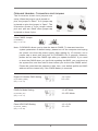
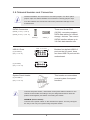
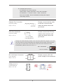
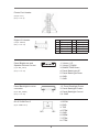
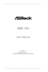
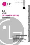
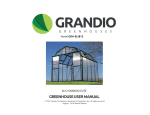
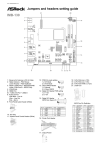
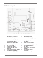
Motherboard Layout
1
SET COM Ports 1,2 (SET_CM1,2)
18
SPI Flash Memory (16Mb)
2
LVDS Con (LVDS1)
19
COM Ports 4,5,6 (COM4,5,6)
3
4-Pin DC PWR (DC12V1)
20
SET COM Ports 4,5,6 (SET_CM4,5,6)
4
CPU Fan Connector (CPU_FAN1)
21
Panel Brightness and Speaker Volume
5
2 x DDR3 DIMM Slots
Control (BLT_VOL1)
6
Chassis Fan Connector (CHA_FAN1)
22
Panel Backlight Inverter connector
7
Output Power (SATA_PWR1)
(BLT_PWR2)
8
SATA2 Connector (SATA2_1, Blue)
23
Speaker Connector (SPEAKER1)
9
Printer Port Header (LPT1)
24
PCI1
10
SATA2 Connector (SATA2_2, Blue)
25
Front Panel Audio Header (HD_AUDIO1)
11
USB 2.0 Ports 4,5 (USB4,5)
26
Panel VDD PWR Setting (PNL_PWR1)
12
USB 2.0 Port 6 (USB6)
27
Panel Backlight PWR Setting
13
Digital I/O Header (JGPIO1)
(BKT_PWR1)
14 Digital I/O Header PWR Setting
28
Bottom Side CF Card PWR Setting
(JGPIO_PWR1)(JCFPWR1)
15
16
17
System Panel Control Header (PANEL1)
29
Clear CMOS Header (CLRCMOS1)
PWR-On mode Setting (PWR_JP1)
30
1
Panel Resolution Selection
(JLVD_GPIO1)
SET COM Port 3 (SET_CM3)
Onboard Headers, Connectors and Jumpers
The illustration shows how jumpers are
setup. When the jumper cap is placed on
pins, the jumper is “Short”. If no jumper cap
is placed on pins, the jumper is “Open”. The
illustration shows a 3-pin jumper whose
pin1 and pin2 are “Short” when jumper cap
is placed on these 2 pins.
Clear CMOS Jumper
(CLRCMOS1)
(see p.1, No. 16)
Default
Clear CMOS
Note: CLRCMOS1 allows you to clear the data in CMOS. To clear and reset the
system parameters to default setup, please turn off the computer and unplug
the power cord from the power supply. After waiting for 15 seconds, use a
jumper cap to short pin2 and pin3 on CLRCMOS1 for 5 seconds. However,
please do not clear the CMOS right after you update the BIOS. If you need
to clear the CMOS when you just finish updating the BIOS, you must boot up
the system first, and then shut it down before you do the clear-CMOS action.
Please be noted that the password, date, time, user default profile and MAC
address will be cleared only if the CMOS battery is removed.
Digital I/O Header PWR Setting
(3-pin JGPIO_PWR1)
(see p.1 No. 14)
1-2: +12V.
2-3: +5V.
PWR-On Mode Setting
1-2: AT Mode.
2-3: ATX Mode.
(3-pin PWR_JP1)
(see p.1 No. 17)
Panel VDD PWR Setting
(3-pin PNL_PWR1)
(see p.1 No. 26)
2
1-2: +3.3V.
2-3: +5V.
Panel BackLight PWR Setting
(3-pin BKT_PWR1)
1-2: +5V.
2-3: +12V.
(see p.1 No. 27)
Bottom Side CF Card PWR Setting
(3-pin JCFPWR1)
1-2: +3.3V.
2-3: +5V.
(see p.1 No. 28)
Panel Resolution Selection
(12-pin JLVD_GPIO1)
(see p.1 No. 29)
3
Reserved.
Default set by BIOS.
2.8 Onboard Headers and Connectors
Onboard headers and connectors are NOT jumpers. Do NOT place
jumper caps over these headers and connectors. Placing jumper caps
over the headers and connectors will cause permanent damage of the
motherboard!
SATA2 Connectors
(SATA2_1: see p.1, No. 8)
(SATA2_2: see p.1, No. 10)
SATA2_1
USB 2.0 Ports
(4-pin USB4,5)
(see p.1 No. 11)
(4-pin USB6)
(see p.1 No. 12)
SATA2_2
PWR -4 +4 GND
7
1
8
2
PWR -5 +5 GND
1
These two Serial ATA2
(SATA2) connectors support SATA data cables for internal storage devices. The current SATA2 interface allows up to
3.0 Gb/s data transfer rate.
Besides four default USB 2.0
ports on the I/O panel, there are three USB 2.0 ports on this
motherboard.
4
PWR -6 +6 GND
System Panel Header
This header accommodates
(9-pin PANEL1)
several system front panel (see p.1 No. 15)functions.
Connect the power switch, reset switch and system status indicator on the
chassis to this header according to the pin assignments below. Note the
positive and negative pins before connecting the cables.
PWRBTN (Power Switch):
Connect to the power switch on the chassis front panel. You may configure
the way to turn off your system using the power switch.
4
RESET (Reset Switch):
Connect to the reset switch on the chassis front panel. Press the reset
switch to restart the computer if the computer freezes and fails to perform a
normal restart.
PLED (System Power LED):
Connect to the power status indicator on the chassis front panel. The LED
is on when the system is operating. The LED keeps blinking when the system is in S1 sleep state. The LED is off when the system is in S3/S4 sleep
state or powered off (S5).
HDLED (Hard Drive Activity LED):
Connect to the hard drive activity LED on the chassis front panel. The LED
is on when the hard drive is reading or writing data.
The front panel design may differ by chassis. A front panel module mainly
consists of power switch, reset switch, power LED, hard drive activity LED,
speaker and etc. When connecting your chassis front panel module to this
header, make sure the wire assignments and the pin assign-ments are
matched correctly.
Speaker Connector
(4-pin SPEAKER 1)
(see p.1 No. 23)
1
R+
L-
4
R-
L+
Front Panel Audio Header
(9-pin HD_AUDIO1)
(see p.1 No. 25)
1: Speaker R-
2: Speaker R+
3: Speaker L+
4: Speaker LThis is an interface for front
panel audio cable that allows convenient connection and control of audio devices.
1. High Definition Audio supports Jack Sensing, but the panel wire on the chassis must support HDA to function correctly. Please follow the instruction in our manual and chassis manual to install your system.
2. If you use AC’97 audio panel, please install it to the front panel audio header as below:
A. Connect Mic_IN (MIC) to MIC2_L.
B. Connect Audio_R (RIN) to OUT2_R and Audio_L (LIN) to OUT2_L.
C. Connect Ground (GND) to Ground (GND).
D. MIC_RET and OUT_RET are for HD audio panel only. You don’t need to connect them for AC’97 audio panel.
5
E. To activate the front mic.
For Windows® XP / XP 64-bit OS:
Select “Mixer”. Select “Recorder”. Then click “FrontMic”.
For Windows® 7 / 7 64-bit / VistaTM / VistaTM 64-bit OS:
Go to the “FrontMic” Tab in the Realtek Control panel. Adjust “Recording Volume”.
Chassis Fan Connector
(3-pin CHA_FAN1)
(see p.1 No. 6)
Please connect the fan cable to the fan connector and match the black wire to the ground pin.
CPU Fan Connector
(4-pin CPU_FAN1)
(see p.1 No. 4)
Please connect the CPU fan
cable to the connector and
match the black wire to the ground pin.
Though this motherboard provides 4-Pin CPU fan (Quiet Fan) support, the 3-Pin CPU fan still can work successfully even without the fan speed control function. If you plan to connect the 3-Pin CPU fan to the CPU fan connector on this motherboard, please connect it to Pin 1-3.
Pin 1-3 Connected
3-Pin Fan Installation
DC 12V Power Connector
(4-pin DC12V1)
(see p.1 No. 3)
12V
12V
GND
GND
COM port 4,5,6
(10-pin COM4,5,6)
(see p.1 No. 19)
6
Please connect a DC 12V power supply to this connector.
SET COM Ports
(10-pin SET_CM1,2)
(see p.1 No. 1)
(10-pin SET_CM4,5,6)
(see p.1 No. 20)
(5-pin SET_CM3)
(see p.1 No. 30)
1
LVDS Con
(40-pin LVDS1)
(see p.1 No. 2)
Output Power
(4-pin SATA_PWR1)
(see p.1 No. 7)
1: +5V
1
2
3
4
2, 3: GND
4. +12V
7
Printer Port Header
(25-pin LPT1)
(see p.1 No. 9)
Digital I/O Header
PIN
1
3
5
7
9
(10-pin JGPIO1)
(see p.1 No. 13)
Panel Brightness and
Speaker Volume Control
(7-pin BLT_VOL1)
(see p.1 No. 21)
1
7
Signal Name
Digital Output 0
Digital Output 1
Digital Output 2
Digital Output 3
PWR
PIN
2
4
6
8
10
Signal Name
Digital Input 0
Digital Input 1
Digital Input 2
Digital Input 3
GND
1: Volume_UP
2: Volume_DOWN
3: PANEL PWR Down
4: Panel BackLight UP
5: Panel BackLight Down
6: GND
7: GND
Panel BackLight Inverter
connector
(6-pin BLT_PWR2)
(see p.1 No. 22)
1,2: Panel Backlight Power
3: Panel Backlight Enable
4: Panel Backlight Control
5,6: GND
RJ-45 COM Port C
(8-pin COM Port C)
1: DCD#
2: RXD
3: TXD
4: DTR#
5: GND
6: DSR#
7: RTS#
8: CTS#
8