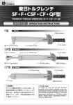
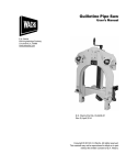
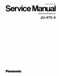
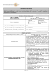
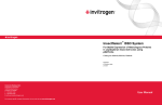
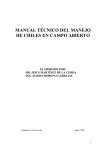
1
MAGNA GRAIN DRYERS
M
MO
OD
DE
ELL 22000055 -->>
JULY 2005
Handbook for the use and maintenance of the dryer
Revision July 2005
Page 2 of 36
1 INTRODUCTION TO THE MANUAL
1.1
FOREWORD
This manual is provided to give you the necessary operating and maintenance instructions to
obtain the best performance and working life for your dryer.
Please read this manual thoroughly. Understand what each control is for and how to use it.
Observe all safety precautions decaled on the machine and noted throughout the manual for
safe operation.
DO NOT CARRY OUT MAINTENANCE WORK AND/OR REPAIRS UNTIL THE TRACTOR
ENGINE IS STOPPED AND THE PTO DISCONECTED OR IF AN ELECTRIC DRIVE UNIT THE
MAIN POWER SWITCH TURNED TO OFF.
DO NOT UNDER ANY CIRCUMSTANCES ENTER THE DRYER THROUGH THE INSPECTION
HATCH UNTIL THE TRACTOR IS TURNED OFF AND THE PTO SHAFT IS COMPLETELY
DISCONTECTED OR IF AN ELECTRIC DRIVE UNIT THE MAIN POWER SWITCH TURNED TO
OFF.
FAILURE TO FOLLOW THIS INSTRUCTION MAY CAUSE SERIOUS INJURY.
EXPLANATION – SHOULD THE AGITATOR ARM RECIRCULATE WHILST THE OPERATOR IS
ENTERING THE DRYER OR INSIDE THE DRYER
If any assistance or additional information is needed, contact your authorized OPICO dealer.
This manual is divided into the following sections:
1)
Introduction
2)
General Information
3)
Preparing The Dryer For Operation
4)
Loading And Operation
5)
Maintenance
6)
Safety Warnings
7)
Trouble Shooting
8)
Storage
9)
Wiring Diagrams
For safety and to obtain the performance of which these machines are capable we
recommend that the operator should read this manual carefully before initial start up at
the beginning of each season and when changing to a new crop type.
Handbook for the use and maintenance of the dryer
Revision July 2005
Page 3 of 36
1.2
INDEX
1
1.1
1.2
1.3
1.4
2
2.1
2.2
2.3
2.4
2.4.1
2.4.2
2.4.3
2.4.4
3.
3.1
3.2
3.3
3.4
3.5
3.6
3.7
4
4.1
4.2
4.3
4.4
4.5
4.6
4.7
5
5.1
5.2
6
6.1
6.2
6.3
6.3.1
6.4
6.5
7
7.1
7.2
7.3
7.4
7.5
7.6
7.7
7.8
8
9
INTRODUCTION TO THE MANUAL............................................................................................ 2
FOREWORD................................................................................................................................ 2
INDEX ......................................................................................................................................... 3
DEFINITION OF SYMBOLS......................................................................................................... 4
SAFE WORKING ENVIRONMENT .............................................................................................. 4
GENERAL INFORMATION .......................................................................................................... 5
OVERVIEW .................................................................................................................................. 5
DRYER IDENTIFICATION ........................................................................................................... 5
DRYER COMPONENTS .............................................................................................................. 6
THEORY OF DRYING ................................................................................................................. 7
HEATING THE GRAIN................................................................................................................. 7
COOLING THE GRAIN ................................................................................................................ 7
RECOMMENDED DRYING TEMPERATURES ........................................................................... 8
TEMPERATURE CONVERSION CHARTS ............................................................................... 12
PREPARING THE DRYER FOR OPERATION.......................................................................... 13
SITING THE DRYER.................................................................................................................. 13
POSITIONING THE TOP FOLD DOWN AUGER....................................................................... 14
PREPARING FOR TRANSPORT............................................................................................... 16
LOADING AUGER HOPPER ..................................................................................................... 16
DIESEL FUEL SUPPLY ............................................................................................................. 16
CONNECT THE PTO SHAFT TO THE TRACTOR .................................................................... 16
CONTROLS ............................................................................................................................... 17
DRYER OPERATION................................................................................................................. 18
CONTROL BOARD .................................................................................................................... 18
PLENUM & GRAIN TEMPERATURE THERMOSTATS............................................................. 19
PLENUM SAFETY CONTROL................................................................................................... 19
THERMIC SAFETY .................................................................................................................... 19
LOADING AND OPERATING .................................................................................................... 20
HOW TO GET THE BEST PERFORMANCE OUT OF YOUR DRYER...................................... 21
FUEL NOZZLE SELECTION AND SETTINGS………………………………………………………22
MAINTENANCE ......................................................................................................................... 23
POINTS TO LUBRICATE........................................................................................................... 23
END OF SEASON OPERATIONS ............................................................................................. 24
SAFETY WARNINGS................................................................................................................. 25
SAFETY PRINCIPLE ................................................................................................................. 25
WARNINGS AND DANGERS .................................................................................................... 26
SAFETY GUARDS AND WARNING LOGOS ............................................................................ 27
EMERGENCY STOP BUTTON.................................................................................................. 27
RESIDUAL RISKS...................................................................................................................... 27
NOISE LEVELS ......................................................................................................................... 27
TROUBLE SHOOTING .............................................................................................................. 28
THE BURNER ............................................................................................................................ 28
DEFLECTOR AND ELECTRODES............................................................................................ 29
HEAT UNIT AIR FLAP ADJUSTMENT ...................................................................................... 30
BURNER DOES NOT LIGHT..................................................................................................... 31
DIESEL SUPPLY FAILURE ....................................................................................................... 31
SMOKE OR EXCESS DIESEL FUMES ..................................................................................... 31
THE AIR MIXTURE IS TOO LEAN AND THE FLAME VERY BRIGHT IN COLOUR................. 31
FUEL CIRCUIT…………………………………………………………………………………………..32
STORAGE.................................................................................................................................. 32
WIRING DIAGRAMS.................................................................................................................. 32
ENCLOSED WITH THIS HANDBOOK
DECLARATION OF CONFORMITY SUPPLIED BY THE MANUFACTURER
PRODUCT REGISTRATION CARD
Handbook for the use and maintenance of the dryer
Revision July 2005
Page 4 of 36
1.3
DEFINITION OF SYMBOLS
Symbols are used in this handbook to highlight parts of its content, which are of special
importance for safety, use and maintenance
SYMBOL
MEANING
DESCRIPTION
ATTENTION
Section of text which includes an
instruction that that requires attention
DANGER
This symbol requires you to pay
special attention because your safety
is involved
USE
Explanation of the correct use of the
dryer
MAINTENANCE
Maintenance Instructions
1.4
SAFE WORKING ENVIRONMENT
Read and understand the operators manual before operating the unit
Always disconnect the PTO shaft or if an electric drive unit turn the main power switch
to off before adjusting, lubricating, servicing or cleaning
Keep all shields and safety devices in place
Keep children, visitors and untrained personnel away from the machine while in
operation
Keep hands, feet and clothing away from moving parts
Keep unit level when operating
DO NOT UNDER ANY CIRCUMSTANCES ENTER THE DRYER THROUGH THE INSPECTION
HATCH UNTIL THE TRACTOR IS TURNED OFF AND THE PTO SHAFT IS COMPLETELY
DISCONTECTED OR IF AN ELECTRIC DRIVE UNIT THE MAIN POWER SWITCH TURNED TO
OFF.
FAILURE TO FOLLOW THIS INSTRUCTION MAY CAUSE SERIOUS INJURY.
EXPLANATION – SHOULD THE AGITATOR ARM RECIRCULATE WHILST THE OPERATOR IS
ENTERING THE DRYER OR INSIDE THE DRYER
Handbook for the use and maintenance of the dryer
Revision July 2005
Page 5 of 36
2 GENERAL INFORMATION
2.1
OVERVIEW
All instructions relating to position are as viewed from the front of the dryer looking toward
the back of the machine.
2.2
DRYER IDENTIFICATION
The Identification Plate and CE marking of the machine is placed on the left side of the
draw-bar.
The identification plate must not be tampered with, covered over or modified in any way.
Should the plate become damaged or lost you should request a replacement as soon as
reasonable possible.
Picture 2.2 IDENTIFICATION PLATE
Handbook for the use and maintenance of the dryer
Revision July 2005
Page 6 of 36
2.3
DRYER COMPONENTS
Picture 2.3 DRYER COMPONENTS TABLE
1) Discharge Chute
10) Grain Cleaner Discharge
2) Vertical Auger
11) Grain Sampler Outlet
3) Plenum Chamber
12) Loading Auger
4) Air Duct
13) Belt Drive
5) Fan
14) Centre Auger Gearbox
6) Heat Unit
15) Adjustable Support Jacks
7) Agitator Gearbox
16) PTO Shaft
8) Agitator Support Rollers
17) Control Board
9) Agitator Arm
18) Main Drive Shaft
Handbook for the use and maintenance of the dryer
Revision July 2005
Page 7 of 36
2.4
THEORY OF DRYING
2.4.1 HEATING THE GRAIN
Combinable crop drying has two basic stages:
1. The diffusing of internal moisture to the surface of the grain, bean or seed.
Followed by:
2. The removal of the created external moisture by air flow.
The grain temperature largely establishes this rate of diffusion and must be controlled not
to exceed a rate that could result in a ruptured seed.
Removal of the exterior moisture is dependant upon air flow and air temperature.
These two stages must be balanced to produce the quality dried crop.
The balance is accomplished quite simply in the Magna Grain Dryer with its uniform
circulation, regulated heat and controlled air-flow.
2.4.2 COOLING THE GRAIN
It is very important to cool grain. Grain to be stored should be cooled after drying
to within 15 degrees F of atmospheric temperature or 10 degrees F of grain already in the
storage bin. Moisture migration from air to grain will occur if the grain is not cooled within
these limits.
Handbook for the use and maintenance of the dryer
Revision July 2005
Page 8 of 36
2.4.3 RECOMMENDED DRYING TEMPERATURES
CROP TYPE
BARLEY
Feed
Malting/Seed
MOISTURE CONTENT &
POINTS OF INTEREST
Below 21%
Above 22%
PLENUM
TEMPERATURE
MAXIMUM
FINAL GRAIN
TEMPERATURE
FINAL STORAGE
LEVEL
180 - 200°F
120 - 150°F
110 - 130°F
120°F
105°F
105°F
14%
If light samples are experienced Maximum Plenum Temperature should not exceed 140°F
WARNING
Great care should be taken with the storage of barley grown for malting or seed
between the actual harvesting of the material and the drying of it. Harvested crop must
only be stored before drying for the minimum amount of time. It is recommended that
the crop is stored so that the maximum depth does not exceed 2 feet.
CROP TYPE
MOISTURE CONTENT &
POINTS OF INTEREST
PLENUM
TEMPERATURE
MAXIMUM
FINAL GRAIN
TEMPERATURE
FINAL STORAGE
LEVEL
160 - 200°F
120°F
8%
OILSEED RAPE
Up to 17%
SPECIAL NOTES
1. Plenum temperatures of up to 200°F have been used without apparent oil/quality loss
2. Excessive heat gives slower drying – cooling prolonged
3. Mature crops dry relatively easily
4. Desiccated early crops may contain 30% volume of immature seeds which are less easily
dried
5. With moisture content above 17% - for every 2% increase in moisture content, reduce
plenum temperature by 10°F for the initial drying period
CROP TYPE
OILSEED RAPE
Seed
MOISTURE CONTENT &
POINTS OF INTEREST
Reduce plenum
temperature by 10°F
PLENUM
TEMPERATURE
MAXIMUM
FINAL GRAIN
TEMPERATURE
FINAL STORAGE
LEVEL
120 - 150°F
105°F
8%
Handbook for the use and maintenance of the dryer
Revision July 2005
Page 9 of 36
FINAL STORAGE
MAXIMUM
FINAL GRAIN
LEVEL
TEMPERATURE
HERBAGE SEEDS (SAFE DRYING AIR TEMPERATURES FOR 90% GERMINATION)
(Grass Seed)
PRG/IRG
Up to 25%
13%
130°F
90°F
Between 25% – 30%
13%
120°F
90°F
Between 30% – 35%
13%
110°F
90°F
Between 35% – 40%
13%
100°F
90°F
CROP TYPE
MOISTURE CONTENT &
POINTS OF INTEREST
PLENUM
TEMPERATURE
NOTES
*
Always grown for seed
*
Grass seed does not flow easily over 22% moisture content
*
Polish the dyer prior to use with dried barley or other dry grain
BEANS – see Peas/Field Beans
CROP TYPE
LINSEED
Oil extraction
and/or seed
MOISTURE CONTENT &
POINTS OF INTEREST
Up to 15%
PLENUM
TEMPERATURE
MAXIMUM
FINAL GRAIN
TEMPERATURE
FINAL STORAGE
LEVEL
120 - 150°F
120°F
8%
*For every 2% increase in moisture content reduce plenum temperature by 10°°F
CROP TYPE
OATS
Feed
Seed
MOISTURE CONTENT &
POINTS OF INTEREST
90 - 120°F
105°F
8%
PLENUM
TEMPERATURE
MAXIMUM
FINAL GRAIN
TEMPERATURE
FINAL STORAGE
LEVEL
150 - 200°F
110 - 150°F
130°F
105°F
14%
14%
NOTE Oats for feed use can stand plenum temperatures up to 220°F.
Handbook for the use and maintenance of the dryer
Revision July 2005
Page 10 of 36
CROP TYPE
MOISTURE CONTENT &
POINTS OF INTEREST
PLENUM
TEMPERATURE
MAXIMUM
FINAL GRAIN
TEMPERATURE
FINAL STORAGE
LEVEL
PEAS/FIELD BEANS
Processing /
14%
110 - 120°F
105°F
Protein
NOTE In general protein is not affected by heat but excessive heat will cause splitting damage
Seed
Below 24%
14%
90 - 110°F
105°F
Seed
Above 24%
14%
70 – 90°F
105°F
Seed
Above 27%
14%
No heat to 50°F
105°F
DIRECT HARVESTED
1. Can experience handling problems over 25% moisture content
2. Do not use loading auger over 25% moisture content (see below)
3. Special note – clean out the centre auger bin bottom after each load. This crop carries a lot
of surface dirt which in the re-circulation process will find its way to the bin bottom well and
create an extremely abrasive paste. This will shorten the life of the centre auger
dramatically if the recommended cleaning process is not carried out.
DRYING FROM STORE
1. This crop is susceptible to splitting if excessive heat is used
2. Increase temperature in 5°F stages and check for splits to a maximum of 110°F plenum
temperature : No heat - 110°F
CROP TYPE
WHEAT
Feed
Milling
MOISTURE CONTENT &
POINTS OF INTEREST
Below 25%
Above 25%
Seed
PLENUM
TEMPERATURE
MAXIMUM
FINAL GRAIN
TEMPERATURE
FINAL STORAGE
LEVEL
180 - 200°F
150 - 180°F
140 – 170°F
100 - 130°F
140°F
120°F
120°F
105°F
14%
14%
14%
14%
SPECIAL NOTES
1. High gluten wheats mean slower drying
2. Wet cereals in general i.e. over 27% moisture content – dry carefully do not exceed Grain
Final Safe Temperature. If this is apparent, stop the burner, allow dryer to continue
circulating grain until cool, then re-light the burner and complete the drying process.
3. Seed wheat over 27% moisture content – use no heat to a maximum of 105°F plenum until
moisture content is below 20%, then continue with care using a plenum temperature of
120°F maximum.
Handbook for the use and maintenance of the dryer
Revision July 2005
Page 11 of 36
CROP TYPE
MOISTURE CONTENT &
POINTS OF INTEREST
LUPINS
Drying for Seed
PLENUM
TEMPERATURE
MAXIMUM
FINAL GRAIN
TEMPERATURE
FINAL STORAGE
LEVEL
no heat to
120°F
*
Furry seed – may generate fluff in handling
*
Very tough skin
*
Pre-drying treatment – pre-cleaning helpful if not essential
METHOD
1. Polish dryer with barley prior to handling
2. Be careful if moisture content 23% - 24% - augers may not handle
3. Recommended plenum temperatures no heat - 105°F - 120°F ABSOLUTE MAXIMUM
Handbook for the use and maintenance of the dryer
Revision July 2005
Page 12 of 36
2.4.4 TEMPERATURE CONVERSION CHART
EG 120°F
= 48.9°C OR 120°C = 248°F
0 ~ 90
°C
-17.8
-15.0
-12.2
-9.4
-6.7
-3.9
-1.1
1.7
4.4
7.2
10.0
10.6
11.1
11.7
12.2
12.8
13.3
13.9
14.4
15.0
15.6
16.1
16.7
17.2
17.8
18.3
18.9
19.4
20.0
20.6
21.1
21.7
22.2
22.8
23.3
23.9
24.4
25.0
25.6
26.1
26.7
27.2
27.8
28.3
28.9
29.4
30.0
30.6
31.1
31.7
32.2
91 ~ 141
°F
0
5
10
15
20
25
30
35
40
45
50
51
52
53
54
55
56
57
58
59
60
61
62
63
64
65
66
67
68
69
70
71
72
73
74
75
76
77
78
79
80
81
82
83
84
85
86
87
88
89
90
°C
32.0
41.0
50.0
59.0
68.0
77.0
86.0
95.0
104.0
113.0
122.0
123.8
125.6
127.4
129.2
131.0
132.8
134.6
136.4
138.2
140.0
141.8
143.6
145.4
147.2
149.0
150.8
152.6
154.4
156.2
158.0
159.8
161.6
163.4
165.2
167.0
168.8
170.6
172.4
174.2
176.0
177.8
179.6
181.4
183.2
185.0
186.8
188.6
190.4
192.2
194.0
32.8
33.3
33.9
34.4
35.0
35.6
36.1
36.7
37.2
37.8
38.3
38.9
39.4
40.0
40.6
41.1
41.7
42.2
42.8
43.3
43.9
44.4
45.0
45.6
46.1
46.7
47.2
47.8
48.3
48.9
49.4
50.0
50.6
51.1
51.7
52.2
52.8
53.3
53.9
54.4
55.0
55.6
56.1
56.7
57.2
57.8
58.3
58.9
59.4
60.0
60.6
142 ~ 260
°F
91
92
93
94
95
96
97
98
99
100
101
102
103
104
105
106
107
108
109
110
111
112
113
114
115
116
117
118
119
120
121
122
123
124
125
126
127
128
129
130
131
132
133
134
135
136
137
138
139
140
141
195.8
197.6
199.4
201.2
203.0
204.8
206.6
208.4
210.2
212.0
213.8
215.6
217.4
219.2
221.0
222.8
224.6
226.4
228.2
230.0
231.8
233.6
235.4
237.2
239.0
240.8
242.6
244.4
246.2
248.0
249.8
251.6
253.4
255.2
257.0
258.8
260.6
262.4
264.2
266.0
267.8
269.6
271.4
273.2
275.0
276.8
278.6
280.4
282.2
284.0
285.8
°C
61.1
61.7
62.2
62.8
63.3
63.9
64.4
65.0
65.6
66.1
66.7
67.2
67.8
68.3
68.9
69.4
70.0
70.6
71.1
71.7
72.2
72.8
73.3
73.9
74.4
75.0
75.6
76.1
76.7
77.2
77.8
78.3
78.9
79.4
82.2
85.0
87.8
90.6
93.3
96.1
98.9
101.7
104.4
107.2
110.0
112.8
115.6
118.3
121.1
123.9
126.7
°F
142
143
144
145
146
147
148
149
150
151
152
153
154
155
156
157
158
159
160
161
162
163
164
165
166
167
168
169
170
171
172
173
174
175
180
185
190
195
200
205
210
215
220
225
230
235
240
245
250
255
260
287.6
289.4
291.2
293.0
294.8
296.6
298.4
300.2
302.0
303.8
305.6
307.4
309.2
311.0
312.8
314.6
316.4
318.2
320.0
321.8
323.6
325.4
327.2
329.0
330.8
332.6
334.4
336.2
338.0
339.8
341.6
343.4
345.2
347.0
356.0
365.0
374.0
383.0
392.0
401.0
410.0
419.0
428.0
437.0
446.0
455.0
464.0
473.0
482.0
491.0
500.0
Handbook for the use and maintenance of the dryer
Revision July 2005
Page 13 of 36
3
PREPARING THE DRYER FOR OPERATION
3.1
SITING THE DRYER
Select a site as level as possible 50 feet (15 metres) from inflammable
buildings. It is preferable to set the machine with the fan facing toward the prevailing
wind.
If the dryer is being set on a level concrete slab simply lower the adjustable jacks, raising
the wheels slightly off the ground, bringing the machine to a level position. It is important
that the central auger is vertical. Use the spirit levels that are positioned on the dryer
transport chassis.
If the dryer has been placed straight on to soil then a board of at least 2" x 8" x 12"
should be placed under each leg.
Handbook for the use and maintenance of the dryer
Revision July 2005
Page 14 of 36
3.2
POSITIONING THE TOP FOLD DOWN AUGER
THERE IS A CORRECT METHOD THAT MUST BE FOLLOWED:
Step One:
At the rear of the dryer there is a 4mtr long round bar mounted vertically
that controls the unloading plate. This is locked in transport position by a large lock screw
on the second ring. This screw must be loosened off to allow the bar to float up with the
extending sheets.
Step Two:
Raise the external extending sheets by approximately 200-300mm,
using the top extension winch.
Step Three:
First examine the illustration (Fig 3A) Climb the external ladder and
stand on the plenum. Using the lever marked 1, pull the over-centre mechanism bringing
the folding auger toward the centre of the dryer. Lock the lever in position using the wing
nut item number 2.
FAILURE TO FOLLOW STEP TWO WILL RESULT IN MATERIAL DAMAGE TO THE
SIDE SHEETS OF THE DRYER.
FIG 3A - VERTICAL AUGER HINGE OVER-CENTRE MECHANISM
Handbook for the use and maintenance of the dryer
Revision July 2005
Page 15 of 36
3.2
POSITIONING THE TOP FOLD DOWN AUGER
Step Four:
Continue to raise the side sheets that will carry the folding part of the
vertical auger with them until the side sheets are 50-100mm from the top of their
movement range.
Step Five:
Using the vertical auger winch (beside the control cabinet) raise the
folding auger into its vertical position. Once the auger is correctly positioned climb the
ladder and tighten up the wing nut item 3 in Fig 3b.
Step Six:
Continue to raise the external extending sheets fully. Taking care not to
apply excessive force. Mount the four safety pins below the extension support bars.
Step Seven:
Check that the vertical rod controlling the unloading gate as mentioned
in step one is in the correct position and opens/closes freely.
FIG 3B - VERTICAL AUGER FOLDING
DURING WORK THE WINCH WIRE TO THE TOP AUGER SHOULD NOT BE
UNDER TENSION.
Handbook for the use and maintenance of the dryer
Revision July 2005
Page 16 of 36
3.3
PREPARING FOR TRANSPORT
TO PREPARE THE DRYER FOR TRANSPORT FOLLOW ALL THE STEPS
ABOVE IN REVERSE ORDER WITH ONE ADDITIONAL STEP:
First Step:
To start the lowering of the top auger extension pull the wire that is
positioned at the rear of the dryer and has at its end a round steel ring. Obviously you
need to undo the wing nut item 3 in Fig 3b first.
3.4
LOADING AUGER HOPPER
Using the appropriate winch gently lower the loading auger into the horizontal position. In
the process checking that the driving lugs do not directly hit each other. adjust the support
feet at the end of the hopper and check the inner/outer auger sections fit properly and are
sealed to prevent grain loss.
3.5
DIESEL FUEL SUPPLY
The diesel tank is located on the left hand side of the dryer. The fuel supply to the burner
has a filter on the suction side. The filter should be replaced as required, depending on
usage and cleanliness of diesel supply.
The fuel pump is factory set at 12 bar pressure for diesel fuel.
3.6
PTO DRIVE SHAFT
Connect the pto shaft to the tractor. Check that the angle between the pto of the tractor
and the input pto of the dryer is as level as possible to minimise pto shaft vibration.
NOTE; the tractor should not be connected to the drawbar of the dryer during dryer
operation.
Handbook for the use and maintenance of the dryer
Revision July 2005
Page 17 of 36
3.7
CONTROLS
2
3
6
4
1. Grain sampler
2. Top extension support
5
3. Grain Temp Probe
9
7
1
4. Plenum Temp Probe
5. Plenum High Limit Probe
8
6. Generator
7. Control Board
10
8. Emergency Stop
12
11
9. Fan clutch
10. Vertical auger winch
11. Intake auger clutch
12. Jack stand
Picture 3.7 CONTROLS
Handbook for the use and maintenance of the dryer
Revision July 2005
Page 18 of 36
4 DRYER OPERATION
4.1
CONTROL BOARD
1. Plenum Temp Thermostat
3
2
1
2. Volt meter
3. Grain Temp Thermostat
4. Ignition Start/Stop
5. Power indicator
6
6. Isolator switch
4
5
7. Hour clock
7
Picture 4.1 CONTROL BOARD OUTER
8. Transformer
9
8
9. Plenum Safety Thermostat
10. Relay
11. Burner Contactor
10
11
12
13
12. Isolator switch
13. Fuse
14. Burner Overload
14
15
Picture 4.2 CONTROL BOARD INNER
15. Terminal block
Handbook for the use and maintenance of the dryer
Revision July 2005
Page 19 of 36
4.2
PLENUM & GRAIN TEMPERATURE THERMOSTATS
Recommended operating temperatures - Section2.4.3
Plenum & Grain thermostats are factory set to operate in °F and have one temp setting.
Press ‘P’ – the last temperature set point “SP 1” used will appear on the display, using the
‘↑ ‘ key to raise or ‘↓’ key to lower the temperature setting °F. The change will appear on
the display, when the desired temperature appears on the display, press ‘P’ this will save
the new setting and return to the current temperature reading on the probe.
When operating, a light above the symbols ‘ - = + ’ will indicate where the actual
temperature reading is in relation to the preset temperature. Ie If the grain temp setting is
112°F and the grain probe is currently reading 102°F the red light will illuminate above the
‘ – ‘ symbol, when the grain temperature reaches the set temperature 112°F a green light
will illuminate above the ‘ = ‘ symbol.
4.3
PLENUM SAFETY CONTROL
The plenum safety control thermostat is mounted inside the control panel, it safeguards
against excessive plenum temperatures, it’s temperature probe is positioned in the
plenum chamber. During operation, the dryer checks the safety thermostat to make
certain the plenum temperature falls within the safe operating range. If so, operation
continues. Should the thermostat open at any time during operation, power to the control
board will be interrupted, halting operation of the dryer.
The safety thermostat operates in °C and should be set approx 30°C above the running
Plenum Air Temperature setting (Note; Plenum temperature is °F, see temp conversion
chart)
ie Plenum temperature set at 180°F – set safety thermostat at 112°C
4.4
THERMIC SAFETY
The thermic safety indicates if any of the electric motor circuit breakers have tripped. This
protects the motor from over loading, ie if an auger was to jam. Check all the circuit
breakers and reset any which have tripped – checking the driveline and motor in
question.
Handbook for the use and maintenance of the dryer
Revision July 2005
Page 20 of 36
4.5
LOADING AND OPERATION
Start the tractor and set pto speed at approximately 450 rpm. Check the diesel
tank has sufficient fuel.
Engage the ‘loading auger’ using the marked lever and proceed to fill the dryer.
Fill the grain bin until the grain is approx 150 - 250mm below the top rim. This amount
depends on initial grain moisture, as wet grain is heated it will expand. Leaving space at
the top of the dryer provides the additional room needed and prevents the dryer from
spilling over. Disengage the intake when the dryer is full.
DO NOT LEAVE GRAIN IN THE DRYER OVERNIGHT. Grain that remains in the dryer
overnight will absorb moisture and swell. This swelling can cause the vertical auger to
jam.
NOTE; The agitator will automatically disengage on Magna 2000 models during loading,
this is to reduce the grain recirculation during loading and minimise the loading time.
Engage the ‘fan’ using the marked lever. To prolong belt life it is recommended that the
tractor pto speed is reduced by approximately 40% before engaging the fan drive,
engage the lever slowly.
When the belt drive to the fan is engaged, turn the control board power isolator to the
‘ON’ position and speed-up the pto until 380V is showing on the volt meter. The power
indicator lights will illuminate, confirming all three phases are operating.
Set ‘Grain & Plenum thermostats’ to the required temperatures. Ensure the plenum safety
thermostat is set to the correct temperature. These temperature settings can be adjusted
at any time during dryer operation.
Start the ‘Burner motor’, the ignition should complete in 5-10 seconds. It may be
necessary to do this two or three times to ensure the burner has started. Allow 30
seconds between each starting attempt. The green start button will illuminate when it is
operating.
When the grain has reached the pre-set grain temperature, the burner will shut off
automatically. The fan will start cooling the crop.
When the grain has cooled sufficiently, disengage the ‘Fan’ drive.
Open the ‘Discharge guilotine’ to empty the grain bin.
There is an emergency stop button mounted on the control board.
Handbook for the use and maintenance of the dryer
Revision July 2005
Page 21 of 36
4.6
HOW TO GET THE BEST PERFORMANCE OUT OF YOUR DRYER
ON THE FIRST DRYING OF EACH DIFFERENT CROP TYPE ON YOUR FARM PROCEED AS FOLLOWS:
Set the finished grain temperature to 125 degrees F that is well above the setting that you
will finally use.
Check the finished grain temperature gauge reading from time to time. When the grain
temperature has achieved 100 degrees F take your first sample to check for actual grain
moisture.
Depending upon altitude, outside air temperature and if it is a dry or wet day you will
record approximately between 17% and 20% moisture.
Continue to run the dryer and take a further sample of grain at 102 degrees F. Continue
in this fashion until the grain is half a percent above finished moisture content required.
So if you are looking for 14% moisture content and you achieve 14½% at 108 degrees F
press the button marked P, press the down arrow to bring the temperature from 125
degrees down to 108 degrees. The burner will cut off and the cooling cycle will begin,
press P to save this new setting.
When all the grain is cooled take a further sample before emptying the dryer to check the
finished moisture content.
If the finished moisture content is below 14% then you can fine-tune the finished grain
temperature by decreasing the value locked into the finished grain temperature gauge by
1 degree.
After two or three loads you will achieve the right balance for the particular crop type. At
this point write down the plenum temperature you have used and the finishing grain
temperature for that particular type as a future record.
The major variable to consider is not moisture content, outside air temperature etc., but
rather the plenum temperature used. There is a balance between extra heat and
therefore extra fuel usage against time of drying.
The recommendations given in our Crop Drying Recommendations are a good starting
point. (Section 2.4.3)
NOTE:
WHEN DRYING ANY CROPS FOR SEED OR MALTING YOU MUST NOT USE PLENUM AIR
TEMPERATURES HIGHER THAN OUR RECOMMENDATION.
Handbook for the use and maintenance of the dryer
Revision July 2005
Page 22 of 36
4.7
FUEL NOZZLE SELECTION AND SETTINGS
There are occasions when drying temperatures required will vary significantly from the norm.
For example when drying seed crops you may need to use smaller nozzles to achieve the
correct temperatures.
In Rape because of crop density overall air flow is reduced, heat retention is increased and
again it may be necessary to use smaller nozzles.
The following tables show the minimum heat rise and give an indication of the air flap rod
measurements necessary. The air flap measurements will vary between machines and is for
guidance only. (Adjustment details; section 7.3)
Dryer Model – 1200QF
Fan Speed – 1700rpm
Fuel Pressure – 12 Bar (174 psi)
Barley
Barley
Barley
Low heat
nozzle no 1
size
Low heat
air opening
setting
High heat
nozzle no 2
size
High heat
air opening
setting
Heat rise
minimum
Gallons / Hr
mm
Gallons / HR
mm
F (C)
6
5
4
17
23
16
7
6
5
150 (66)
145 (63)
133 (56)
5
16 -19
7
20 – 23
22
Factory Set
Dryer Model – 2000QF
Fan Speed – 1620rpm
Fuel Pressure – 12 Bar (174 psi)
Low heat
nozzle no 1
size
Low heat
air opening
setting
High heat
nozzle no 2
size
High heat
air opening
setting
Heat rise
minimum
Heat rise
maximum
Gallons / Hr
mm
Gallons / HR
mm
F (C)
F (C)
160 (71)
195 (90)
OSR
Wheat
8
8
10
10
OSR
6
22
8
16
8
17
10
23
140 (60)
Factory Set
Handbook for the use and maintenance of the dryer
Revision July 2005
Page 23 of 36
5 MAINTENANCE
Please take care not to over grease. Many of the bearings and rollers on this dryer require
greasing only once per season. More harm will be done by over enthusiastic application than
benefit.
Picture 5.1 POINTS TO LUBRICATE
MAIN SHAFT SUPPORT AND FAN 1,2,3,4 (GREASE LIGHTLY AT THE END OF EACH
SEASON)
OTHER SUPPORTS 5,9,14 (GREASE LIGHTLY AT 1 MONTH INTEVALS AND/OR AT
THE END OF EACH SEASON)
PTO SHAFTS 6,7,8,10: (GREASE ON DAILY BASIS)
THE BEARING ROLLERS: (GREASE LIGHTLY EVERY 20 DAYS)
CHAIN 13: (GREASE AT THE END OF EACH SEASON )
CENTRAL AUGER GEARBOX 11 (CHECK OIL AT END OF EACH SEASON)
TOP AUGER SUPPORT 15: (GREASE LIGHTLY EVERY 15 DAYS.)
Handbook for the use and maintenance of the dryer
Revision July 2005
Page 24 of 36
5.2
END OF THE SEASON OPERATIONS
CHECK CHAIN AND CHAIN TIGHTENER TENSION
COVER AND PROTECT ALL THE ELECTRIC COMPONENTS FROM HUMIDITY
REPLACE THE ROLLER BEARINGS OF THE TIMING BEARING RING, IF NECESSARY
CLEAN THE FAN OF THE BURNER 5 (REFER TO THE DRAWING OF THE BURNER)
CHECK THE VERTICAL AUGER AND THE VERTICAL TUBE FOR WEAR
CHECK THE BELTS’ TENSION
CHECK THE CONDITION OF THE FURNACE’S REFRACTORY MATERIAL
CHECK THE CONDITION OF THE STEEL BOTTOM OF THE FURNACE
CHECK THE CONDITION OF THE PROTECTION GUARD OF THE FAN SUPPORT,
PLACED AT THE EXIT OF THE FURNACE FIRE MOUTH BETWEEN FURNACE AND FAN
CHECK THE CONDITION OF CABLES AND WINCHES
CHECK THE CONDITION OF THE PTO SHAFTS AND THEIR SAFETY GUARDS
Handbook for the use and maintenance of the dryer
Revision July 2005
Page 25 of 36
6
SAFETY WARNINGS
In addition to the design and configuration of equipment, hazard control and accident prevention
are dependent upon the awareness, concern, prudence and proper training of personnel in the
operation, transport, maintenance and storage of equipment. Lack of attention to safety can
result in accident, personal injury, reduction of efficiency and worst of all – loss of life.
Watch for safety hazards and correct deficiencies promptly.
Use the following safety precautions as a general guide to safe operations when using the
machine.
Additional safety precautions are used throughout this manual for specific operating and
maintenance procedures. Read this manual and review the safety precautions often until you
know the limitations.
6.1
SAFETY PRINCIPLE
The following are general rules for the users of the machine:
BEFORE USING THE MACHINE CAREFULLY READ ALL PARTS OF THIS MANUAL.
REFRAIN FROM USING THE DRYER UNTIL THE ENTIRE MANUAL (AND ALL ITS
ATTACHMENTS) ARE UNDERSTOOD.
Handbook for the use and maintenance of the dryer
Revision July 2005
Page 26 of 36
6.2
WARNINGS AND DANGERS
DO NOT ALLOW ANYONE TO OPERATE THE MACHINE WHO IS NOT IN GOOD
PHYSICAL AND MENTAL HEALTH.
KEEP CHILDREN, VISITORS AND ALL UNTRAINED PERSONNEL AWAY FROM THE
MACHINE WHILE IN OPERATION.
DO NOT USE THE DRYER WITHOUT ALL THE SAFETY GUARDS IN THE CORRECT
POSITION.
DO NOT CARRY OUT MAINTENANCE WORK AND/OR REPAIRS UNTIL THE TRACTOR
ENGINE IS STOPPED AND THE PTO DISCONECTED OR IF AN ELECTRIC DRIVE UNIT THE
MAIN POWER SWITCH TURNED TO OFF.
DO NOT UNDER ANY CIRCUMSTANCES ENTER THE DRYER THROUGH THE
INSPECTION HATCH UNTIL THE TRACTOR IS TURNED OFF AND THE PTO SHAFT IS
COMPLETELY DISCONTECTED OR IF AN ELECTRIC DRIVE UNIT THE MAIN SWITCH
TURNED TO OFF. FAILURE TO FOLLOW THIS INSTRUCTION MAY CAUSE SERIOUS
INJURY. EXPLANATION – SHOULD THE AGITATOR ARM RECIRCULATE WHILST THE
OPERATOR IS ENTERING THE DRYER OR INSIDE THE DRYER
DO NOT ALTER THE DIMENSIONS OR SHAPE OF THE ADJUSTABLE JACK FEET.
DO NOT MOVE THE DRYER WITH TYRES THAT ARE DEFLATED OR NOT SUITABLE FOR
SERVICE.
DO NOT MOVE THE MACHINE UNLESS IT IS FULLY IN THE TRANSPORT MODE I.E. WITH
THE LOADING AUGER FULLY RAISED FOLD DOWN AUGER FULLY LOWERED AND THE
EXTENDING SIDE SHEETS FULLY CLOSED.
DO NOT ALLOW ANY OBSTRUCTION TO THE AIR INLET.
DO NOT THROW ANY TYPE OF OBJECT INTO THE DRYER, THE BURNER UNIT AND THE
INLET AIR DUCT.
DO NOT TOUCH THE INSIDE OF THE BURNER BOX ASSEMBLY WHEN IT IS WORKING
OR FOR A PERIOD OF AT LEAST ONE HOUR AFTER WORK.
DO NOT CLIMB OR USE THE
LADDER WITHOUT FIRST STOPPING THE TRACTOR
ENGINE AND DISENGAGING THE PTO SHAFT.
DO NOT ALLOW MORE THAN ONE PERSON TO BE ON THE LADDER AT ANY ONE TIME .
Handbook for the use and maintenance of the dryer
Revision July 2005
Page 27 of 36
6.3
SAFETY GUARDS AND WARNING LOGOS
For safety the dryer is supplied with the necessary safety guards and warning logos.
SHOULD THE SAFETY GUARDS BE REMOVED TO CARRY OUT MAINTENANCE OR
CLEANING IT IS THE OPERATORS RESPONSIBILTY TO ENSURE THAT THEY ARE
REPLACED IN THEIR ORIGINAL POSITION PRIOR TO OPERATING THE DRYER.
6.3.1
EMERGENCY STOP BUTTON
The red emergency button is positioned on the front of the main control panel: if pushed it
instantly stops all electrical power to the machine. It is shown in picture 3.7
6.4
RESIDUAL RISKS
Some residual risks cannot be avoided in the natural process of grain drying.
following list is indicative not exhaustive
The
DO NOT PLACE YOUR HANDS OR ANY OTHER PART OF THE BODY THROUGH THE SAFETY
MESH POSITIONED OVER THE LOADING AUGER
BE AWARE OF POSIBLE DANGER WHILT LOWERING THE LOADING AUGER INTO ITS
WORKING POSITION
BE AWARE OF POSIBLE DANGER WHEN POSITIONING THE DRYER USING THE
ADJUSTABLE JACKS
BE AWARE OF POSIBLE DANGER WHEN ATTACHING THE PTO SHAFT TO THE POWER
TAKE OFF OF THE TRACTOR
6.5
NOISE LEVELS
The level of acoustic pressure of the Magna mobile dryers has been measured with the
machine loaded while working in a open field on the 4 compass points at 1,5 meters
distance and at 1,6 meters height from ground. The level is between 77dB(A) and 88
dB(A).
Handbook for the use and maintenance of the dryer
Revision July 2005
Page 28 of 36
7
7.1
TROUBLE SHOOTING
THE BURNER
Picture 7.1 BURNER
1) Burner body
2) Sucking mouth
3) Motor
4) Motor flange
5) Fan
6) Jack body
7) Shaft
8) Gasket
9) Connection plaque
10) Hinge flange
11) Hinge pivot
12) Conveying tube
13) Nosepiece
14) Deflector
15) Support
16) Insulating gasket
17) Hinge
18) Hinge shaft
19) Glass
20) Glass spring
21) Electromagnetic valve
22) Coil E. V.
23) Photo-resistance
24) Electrode ignition
25) Electrode cable
26) Multiple socket
27) Multiple plug
28) Joint plug
29) Joint motor side
30) Joint pump side
31) Pump
32) Tube electro valve
33) Tube jack
34) Starter transformer
Handbook for the use and maintenance of the dryer
Revision July 2005
Page 29 of 36
7.2
DEFLECTOR AND ELECTRODES
Low Flame
High Flame
Picture 7.2 DEFLECTOR AND ELECTRODES POSITION
7.3
HEAT UNIT AIR FLAP ADJUSTMENT
1) High heat 2° flame calibration air
screw
(opens air by turning anticlockwise)
2) Screw locking nut – 2° flame air
adjustment
3) Low heat 1° flame air calibration nut
(open air by turning anticlockwise)
4) Nut locking check-nut
1° flame adjustment
No 2 nozzle
N.B.: If only the number 1 air flow
adjusted, no further adjustment
required. If the number 2 adjuster
altered there will be a requirement
also correct the number 1 setting.
is
is
is
to
No 1 nozzle
Picture 7.3 HEAT UNIT AIR FLAP ADJUSTMENT
Handbook for the use and maintenance of the dryer
Revision July 2005
Page 30 of 36
7.4
7.5
7.6
BURNER DOES NOT LIGHT
1.
Clean the photocell (23) removing any dust or soot.
2.
Check the adjustment of the ignition electrodes (24).
3.
Check the start button (11).
4.
Check that the emergency button (3) has not been pushed.
DIESEL SUPPLY FAILURE
1.
Check the fuel supply lines to ensure that there are no air leaks.
2.
Check the line filter.
3.
Check the diesel circuits and ensure that the electric valve is working correctly; a
click should be heard near it.
4.
Disassemble and clean the jets.
5.
Check that the adjustable high limit rotary dial is not in itself cutting off the burner.
SMOKE OR EXCESS DIESEL FUMES
1.
There is insufficient air for a correct burn. Adjust the air flow calibration as in
paragraph 7.3.
2.
If the nozzles are more than one year old they should be replaced.
3.
The nozzles are dirty and need to be cleaned.
4.
Check that the nozzle’s are correctly screwed into the nozzle holder.
5.
Ensure that the swirl plate inside the nozzle head is tight.
6.
You may need to reduce the low flame nozzle to a smaller GPM size.
7.7 THE AIR MIXTURE IS TOO LEAN AND THE FLAME VERY BRIGHT IN
COLOUR
1.
There is too much air for a correct burn – adjust the air-flow as in paragraph 7.3
by decreasing the air-flap aperture.
2.
The diesel burner pump is producing too little pressure - adjust the pump to a
pressure of 12 bar.
Handbook for the use and maintenance of the dryer
Revision July 2005
Page 31 of 36
7.8 FUEL CURCUIT
8
STORAGE
FOR OVER WINTER STORAGE IT IS ADVISABLE TO KEEP THE DRYER IN A
COVERED AND DRY PLACE. SUITABLY PROTECT THE CONTROL PANEL AND THE
DIESEL BURNER UNIT.
WHETHER THE MACHINE IS IN TRANSPORT MODE OR FULLY EXTENDED REMOVE
THE WEIGHT FROM THE TYRES USING THE ADJUSTABLE JACKS.
Handbook for the use and maintenance of the dryer
Revision July 2005
Page 32 of 36
9
WIRING DIAGRAMS
0
A
1
1
M1
2
M1
3
M1
4
M1
2
3
L1
5
6
7
8
9
L1
L2
L2
L3
L3
NL
NL
M1 PE
PE
IG
B
4
PE
ISOLATOR SWITCH
N
T
S
R
20A
R
S
2.0A
T
C
N
SQ1
2.0E
FU2
3.4E
T
S
S
N2
R2
R2
R2
N2
T1
S1
KA3
230V
24V
V
BT2
Ne
T
Ne
VOLT METER
4AGG
Ne
N
PE
HL1
10 8
M1 M1
2
5
6
7
M1 M1 M1
E
FU3
1
W1
V1
U1
BT1
S
R
0V
24V
KM1
PV1
N
TC
50VA
S3
D
POWER SIGNAL
BURNER
3.1B
3.1F
M1
3
TRANSFORMER
TEMP THERMOSTATS
IGNITION
BT1 = GRAIN TEMP
BT2 = PLENUM TEMP
F
automazi
tel..+39 049 9802267 fax.+39 049 9802712
P.I..03250410283
e-mail: [email protected]
DIVIETO DI APPLICAZIONE RIPRODUZIONE DIVULGAZIONE NEI TERMINI DI LEGGE
COMMESSA
FOGLIO
1
AGRIMEC
TIPO
NUMERO FOGLI
AS / OPICO N 2000
DENOMINAZIONE
1/4
NUMERAZIONE TIPO
CIRCUITO POTENZA
DATA
09/06/2003
CODICE
DIS.
--PEZZI
VISTO
A PLOTTER
DIVIETO DI APPLICAZIONE RIPRODUZIONE DIVULGAZIONE NEI TERMINI DI LEGGE
Revision July 2005
DITTA
di Luigi Benetollo
Via Noalese,64 35010 Vigonza (PADOVA) Italy
Page 33 of 36
due bi automazi
Handbook for the use and maintenance of the dryer
R1
6AGG
1
0
3
4
5
6
7
8
9
S
1.8C
S
A
2
KM1
S4
B
S4
BT2
S4
S4
S04
C
12
M1
9
M1
KA2
EV2
EV1
N
N
N4
BF1
E
1.8C
N
FLAME
N
N
SECONDARY
PRIMARY BURNER
F
automazi
AGRIMEC
tel..+39 049 9802267 fax.+39 049 9802712
P.I..03250410283
e-mail: [email protected]
DIVIETO DI APPLICAZIONE RIPRODUZIONE DIVULGAZIONE NEI TERMINI DI LEGGE
TIPO
AS / OPICO N 2000
DENOMINAZIONE
COMMESSA
FOGLIO
2
NUMERO FOGLI
2/4
NUMERAZIONE TIPO
CIRCUITI AUSILIARI (CONTROLLO BRUCIATORE)
DATA
09/06/2003
CODICE
DIS.
--PEZZI
VISTO
A PLOTTER
DIVIETO DI APPLICAZIONE RIPRODUZIONE DIVULGAZIONE NEI TERMINI DI LEGGE
Revision July 2005
DITTA
di Luigi Benetollo
Via Noalese,64 35010 Vigonza (PADOVA) Italy
Page 34 of 36
due bi automazi
Handbook for the use and maintenance of the dryer
11
M1
D
1
2
3
4
1
5
6
7
8
9
1
1.3E
2
A
1
9
3
3
3
SB1
SB2
8
4
B
KA2
5
06
SB3
SQ1
4
BT1
07
C
13
M1
14
M1
9
8
7
1.1C
7
D
7
Page 35 of 36
Revision July 2005
Handbook for the use and maintenance of the dryer
0
PT1
KM1
HL1
h
E
1.3E
2
2
2
2
KA3
K01
2
2
SAFETY SWITCH
HOUR CLOCK
F
due bi automazi
DITTA
automazi
tel..+39 049 9802267 fax.+39 049 9802712
P.I..03250410283
e-mail: [email protected]
DIVIETO DI APPLICAZIONE RIPRODUZIONE DIVULGAZIONE NEI TERMINI DI LEGGE
COMMESSA
FOGLIO
AGRIMEC
di Luigi Benetollo
Via Noalese,64 35010 Vigonza (PADOVA) Italy
TIPO
3
NUMERO FOGLI
AS / OPICO N 2000
DENOMINAZIONE
3/4
NUMERAZIONE TIPO
CIRCUITO AUSILIARI
DATA
09/06/2003
CODICE
DIS.
--PEZZI
VISTO
A PLOTTER
DIVIETO DI APPLICAZIONE RIPRODUZIONE DIVULGAZIONE NEI TERMINI DI LEGGE
0
1
2
3
4
5
6
7
8
9
A
PE
L1
L2
L3
NL
PE
U1
V1
W1
N
S04
S3
N4
S4
07
7
B
14
12
11
13
10
7
8
9
6
4
5
3
2
PE
L1
L2
L3
NL
PE
U1
V1
W1
N
S04
S3
N4
S4
07
7
D
E
F
automazi
tel..+39 049 9802267 fax.+39 049 9802712
P.I..03250410283
e-mail: [email protected]
DIVIETO DI APPLICAZIONE RIPRODUZIONE DIVULGAZIONE NEI TERMINI DI LEGGE
COMMESSA
FOGLIO
AGRIMEC
TIPO
4
NUMERO FOGLI
AS / OPICO N 2000
DENOMINAZIONE
4/4
NUMERAZIONE TIPO
MORSETTIERA
DATA
09/06/2003
CODICE
DIS.
--PEZZI
VISTO
A PLOTTER
DIVIETO DI APPLICAZIONE RIPRODUZIONE DIVULGAZIONE NEI TERMINI DI LEGGE
Revision July 2005
DITTA
di Luigi Benetollo
Via Noalese,64 35010 Vigonza (PADOVA) Italy
Page 36 of 36
due bi automazi
Handbook for the use and maintenance of the dryer
1
C