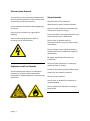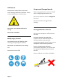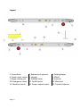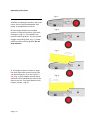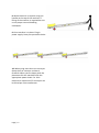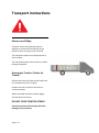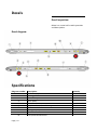
1
Operators manual Shifta 300 - 3.2/4.4/5.4 Shifta 450 - 3.2/4.4/5.4 SAFETY RULES Shifta 300/450 Conveyor Danger Failure to obey the instructions and safety rules in this manual will result in death or serious injury. Do Not Operate Unless: You learn and practice the principles of safe machine operation contained in this operator's manual. 1 Avoid hazardous situations. Know and understand the safety rules before going on to the next section. 2 Always perform a pre-operation inspection. 3 Always perform function tests prior to use. 4 Inspect the workplace. 5 Only use the machine as it was intended. You read, understand and obey: Manufacturer's instructions and safety rules—safety and operator's manuals and machine decals employer's safety rules and worksite regulations applicable governmental regulations. You are properly trained to safely operate the machine Page | 2 Important Read, understand and obey these safety rules and operating instructions before operating this machine. Only trained and authorized personnel shall be permitted to operate this machine. This manual should be considered a permanent part of your machine and should remain with the machine at all times. If you have any questions, please call Mace Industries. Contents Safety………………………………………….……..4 Legend….…………………………………….……..6 Controls………………………………………….....7 Pre-operation inspection…………………...8 Maintenance……………………………….……10 Function tests.…………………………………..12 Work place inspection……………………….14 Operating instructions……………….……..15 Transport instructions……………….………18 Decals………………………………………..……..19 Specifications…………………………….………20 Contact us Web: www.maceindustries.co.uk Tel: 01536 206 600 Fax: 01536 206173 Page | 3 Electrocution Hazards This machine is not electrically insulated and will not provide protection from contact with or proximity to electrical current. Do not operate the machine during lightning or storms. Do not use the machine as a ground for welding. Ensure safe routing of power cable to minimise risk of electrocution. Setup Hazards Check work area for overhead obstructions or other possible hazards. Do not use the machine whilst under the influence of alcohol or drugs. Ensure machine is securely fastened at the top and brakes are on before use. Do not alter or disable machine components that in any way affect safety and stability. Do not replace items critical to machine stability with items of different weight or specification. Be aware of ground surface prior to installation. Explosion and Fire Hazards Do not operate the machine in hazardous locations or locations where potentially flammable or explosive gases or particles may be present. Do not use the machine on a moving or mobile surface or vehicle. Ensure all tyres are in good condition and cotter pins are properly installed. Do not ride on machine. Do not alter or disable limit switches or remote handset. Do not operate the machine in strong or gusty winds. Page | 4 Fall Hazards Always erect a safety barrier to prevent access through underside of machine. Failure to do so could result in serious injury. Component Damage Hazards When using a generator, ensure it is fitted with a voltage regulator before use. Do not over load the machine 150kg MAX belt load. Do not use machine as a ground for welding. Do not lean over machine while belt is moving. Do not ride on machine. Bodily Injury Hazard Use common sense and planning when installing and operating the machine. Keep hands and limbs away from moving belt. Always wear correct PPE. Damaged Machine Hazard Do not use a damaged or malfunctioning machine. Conduct a thorough pre-operation inspection of the machine and test all functions before each work shift. Immediately tag and remove from service a damaged or malfunctioning machine. Be sure all maintenance has been performed as specified in this manual and the appropriate Mace Industries service manual. Be sure all decals are in place and legible Page | 5 Legend 1. Drive drum 4. Power input socket 7. Bogey locking pin 10. Emergency stops 13. Machine trestle Page | 6 2. Bottom belt adjuster 5. Hopper 8. Scaffold holes 11. Forklift point 14. Power output socket 3. Folding bogey 6. Wheel 9. Controls 12. Main belt 15. Top belt adjuster Controls 1. Emergency stop 3. Stop 5. Fast/ Slow Page | 7 2. Forward 4. Reverse Pre-operation Inspection Fundamentals It is the responsibility of the operator to perform a pre-operation inspection and routine maintenance. Do not operate unless: You learn and practice the principles of safe machine operation contained in this operator's manual. 1 Avoid hazardous situations. 2 Always perform a pre-operation inspection. Know and understand the pre-operation inspection before going on to the next section. 3 Always perform function tests prior to use. 4 Inspect the workplace. 5 Only use the machine as it was intended. The pre-operation inspection is a visual inspection performed by the operator prior to each work shift. The inspection is designed to discover if anything is apparently wrong with a machine before the operator performs the function tests. The pre-operation inspection also serves to determine if routine maintenance procedures are required. Only routine maintenance items specified in this manual may be performed by the operator. Refer to the list on the next page and check each of the items and locations for modifications, damage or loose or missing parts. A damaged or modified machine must never be used. If damage or any variation from factory delivered condition is discovered, the machine must be tagged and removed from service. Repairs to the machine may only be made by a qualified service technician, according to the manufacturer's specifications. After repairs are completed, the operator must perform a preoperation inspection again before going on to the function tests. Scheduled maintenance inspections shall be performed by qualified service technicians, according to the manufacturer's specifications. Page | 8 Pre-operation Inspection Be sure that all decals are legible and in place. See Decals section. Be sure the main belt is properly tensioned and in good condition. Check entire machine for: o Cracks in welds or structural components o Dents or damage to the machine Be sure the correct accessories are present. See parts list. Check the following components or areas for damage, modifications and improperly installed or missing parts: o Electrical components o Wiring o Power sockets o Belt rollers o Drive motor o Tyres and wheels o Brakes o Power on lights o Nuts, bolts and other fasteners Page | 9 o Be sure that all structural and other critical components are present and all associated fasteners and pins are in place and properly tightened. Maintenance Check main belt tension and tracking: Observe and Obey: Only routine maintenance items specified in this manual shall be performed by the operator. Scheduled maintenance inspections shall be completed by qualified service technicians, according to the manufacturer's specifications and the requirements specified in the responsibilities manual. Maintenance symbols legend: The following symbols have been used in this manual to help communicate the intent of the instructions. When one or more of the symbols appear at the beginning of a maintenance procedure, it conveys the meaning below. Indicates tools will be needed to carry out this operation. Page | 10 Maintaining the proper belt tension is essential to good machine performance and service life. Operating the machine with an improper belt tension can damage machine components. Check belt tension whilst power is off. 1. Belt will only need to be tensioned if it is slipping under load. 2. At the head of machine loosen the left 12mm bolt holding the drum. 3. With a bar/ screwdriver lever the cam tensioner away from the machine. 4. Repeat to the right side. 5. Turn on conveyor and run belt forwards. 6. Observe the belt tracking. 7. If the belt is drifting to the right, loosen the right hand 12mm bolt and lever the cam tensioner away from machine. 8. Repeat left or right as needed. 9. Tighten bolts and check. Check wheel brakes: Maintaining the brakes is an essential aspect of machine maintenance. Whilst erecting a machine the operator depends on the brakes functioning. Check brake function whilst machine is flat on the ground. 1. Move the brake arm back and forth to its extent of travel. Ensure it moves freely. o If brake won’t move or is stiff grease and retry. 2. Ensure wheel cannot be moved whilst brake is operated. ___________________________________ Check belt roller condition: Ensuring no muck or debris is built up on or around the rollers is essential to ensure good performance and service life. Check belt rollers whilst power is off. 1. Lift belt at base and top of machine. 2. Inspect the condition of steel pitching rollers. 3. Move along the machine checking the rollers are free moving and free of debris or build up. 4. If a roller is seized, replace straight away as this can damage the belt and cause tracking issues. ____________________________________ Page | 11 Scheduled Maintenance Maintenance performed quarterly and annually must be completed by a person trained and qualified to perform maintenance on this machine according to the procedures found in the service manual for this machine. Machines that have been out of service for more than three months must receive the quarterly inspection before they are put back into service. _________________________________ Function tests Fundamentals The function tests are designed to discover any malfunctions before the machine is put into service. The operator must follow the step-bystep instructions to test all machine functions. Do not operate unless: You learn and practice the principles of safe machine operation contained in this operator's manual. 1 Avoid hazardous situations. 2 Always perform function tests prior to operation. Know and understand the function tests before going on to the next section. 3 Always perform function tests prior to use. 4 Inspect the workplace. 5 Only use the machine as it was intended. Page | 12 A malfunctioning machine must never be used. If malfunctions are discovered, the machine must be tagged and removed from service. Repairs to the machine may only be made by a qualified service technician, according to the manufacturer's specifications. After repairs are completed, the operator must perform a pre-operation inspection and function tests again before putting the machine into service. Function tests: 1. Select and area that is firm level and free of obstruction. 2. Plug 110v power into input socket. o Observe the centre red button on control box. The button should be illuminated. o The yellow fast/ slow button should also illuminate. At the controls: 3. Press the emergency stop button. o The centre red button should flash indicating a stop circuit function. 4. Press forward and reverse buttons. o Belt should not move. 5. Pull out emergency stop button. o Red light should return to being permanently illuminated. Test the up and down functions: 6. Press the forward button. o The belt should move forwards. 7. Press the fast/ slow button. o Belt will speed up. 8. Wait 5 sec then press the fast/ slow button. o Belt will slow down. 9. Press the centre stop button. o The belt should stop. 10. Press the reverse button. o The belt should move in reverse. 11. Press the centre stop button. o Belt should stop Page | 13 If the machine fails any of these function tests, it should be removed from service and repaired. Workplace inspection Fundamentals The workplace inspection helps the operator determine if the workplace is suitable for safe machine operation. It should be performed by the operator prior to moving the machine to the workplace. Do not operate unless: It is the operator's responsibility to read and remember the workplace hazards, then watch for and avoid them while moving, setting up and operating the machine. You learn and practice the principles of safe machine operation contained in this operator's manual. 1 Avoid hazardous situations. 2 Always perform function tests prior to operation. Workplace Inspection Be aware of and avoid the following hazardous situations: 3 Always perform function tests prior to use. 4 Inspect the workplace. Know and understand the function tests before going on to the next section. 5 Only use the machine as it was intended. Page | 14 Bumps, floor obstructions or debris Slopes Unstable or slippery surfaces Overhead obstructions Hazardous locations Inadequate surface support to withstand all load forces imposed by the machine Wind and weather conditions The presence of unauthorized personnel Other possible unsafe conditions Operating instructions Fundamentals The Operating Instructions section provides instructions for each aspect of machine operation. It is the operator's responsibility to follow all the safety rules and instructions in the operator's, safety and responsibilities manuals. Do not operate unless: You learn and practice the principles of safe machine operation contained in this operator's manual. 1 Avoid hazardous situations. 2 Always perform function tests prior to operation. 3 Always perform function tests prior to use. 4 Inspect the workplace. 5 Only use the machine as it was intended. Page | 15 This conveyor was designed to transport solid (non-liquid/ non-dangerous) material such as stone, sand, rubble and soil. The material must be loaded responsibly and with skill by the operator as to not cause damage by overloading the conveyor. Only trained and authorized personnel should be permitted to operate a machine. If more than one operator is expected to use a machine at different times in the same work shift, they must all be qualified operators and are all expected to follow all safety rules and instructions in the operator's safety and responsibilities manuals. That means every new operator should perform a pre-operation inspection, function tests, and a workplace inspection before using the machine. Operating instructions: Fig. 1. 1. Before installing the machine, plan your route. Ensure you have adequate man power to complete the set tasks. 2. Fold wheels down from transport position. Lift base of machine, pull black locking pin. (Fig. 1.) Push wheels into position and let go of pin. The pin should engage into locking plate. (Fig. 2.) Lower machine safely onto the ground. Do not drop machine. Fig. 2. Fig. 3. 2. Fit hopper to base of machine. Align the slots both sides so they line up with the dome head pins. Pins are shown in red. (Fig. 3.) Push hopper toward top of machine until the domed pin stops at the base of the slot. Then push down to lock hopper in place. (Fig. 4.) Page | 16 Fig. 4. 8. Wheel machine in to place using the handles at the top of the machine. If lifting of the machine is required be sure to use proper manual handling techniques. 9. Once machine is in place. Plug in power supply. Start pre-operation checks. 10. When using more than one conveyor. Setup the first conveyor and work forwards. When you are happy with the placement link the machines with the appropriate power leads. For 110v machines a maximum of 5 conveyors can be linked per 5Kva transformer. Page | 17 Transport instructions Observe and Obey: Common sense and planning must be applied to control the movement of the machine when moving it with a forklift. The transport vehicle must be parked on a level surface. The machines brakes must remain on whilst being transported. Securing to Truck or Trailer for Transit: Always check the machine wheel brakes are on in preparation for transport. Inspect the entire machine for loose or unsecured items. Where possible fold up the wheel bogey and stack the conveyors. DO NOT OVER TIGHTEN STRAPS. Excessive tension of the straps will cause damage to the machine. Page | 18 Decals Decal Inspection: Below is a numerical list with quantities and descriptions. Decal diagram: Specifications Diagram number 1 2 3 4 5 6 7 8 9 10 Page | 19 Description Shifta Max payload Locking pin label 110v 3kva operation Pinch point Max sound Serial number and machine type Shifta name label Emergency stop Made in Britain Two speed and direction Quantity 2 2 1 2 1 1 2 4 2 1 Specification Model 300 Machine weight Maximum belt load Belt speed: Fast slow Maximum angle Drum motor Storage dimensions (flat) Noise emissions (A weighted) Model 450 Machine weight Maximum belt load Belt speed Fast Slow Maximum angle Electric motor Storage dimensions (flat) Noise emissions (A weighted) Page | 20 3.2 103kg 150kg 4.4 126kg 150kg 5.4 140kg 150kg 20m/min 28m/min N/A 0.55kw 0.27m x 3.2m x 0.6m >75dB 20m/min 28m/min N/A 0.55kw 0.27m x 4.4m x 0.6 m >75dB 20m/min 28m/min N/A 0.55kw 0.27m x 5.4m x 0.6 m >75dB 3.2 116kg 200kg 4.4 160kg 200kg 5.4 180kg 200kg 20m/min 28m/min N/A 0.75kw 0.27m x 3.2m x 0.75 m >75dB 20m/min 28m/min N/A 0.75kw 0.27m x 4.4m x 0.75 m >75dB 20m/min 28m/min N/A 0.75kw 0.27m x 5.4m x 0.75 m >75dB