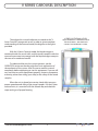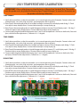
1
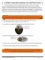
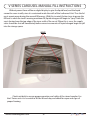
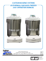
CUSTOM BIOGENIC SYSTEMS ISOTHERMAL CAROUSEL FREEZER 2301 OPERATORS MANUAL www.custombiogenics.com 150 Shafer Drive w Romeo, MI 48065 w USA 1.800.523.0072 w Tel: 1.586.331.2600 w Fax: 1.586.331.2588 Leading the World with Innovative Cryopreservation Technology Solutions European Authorized Representative EC REP EMERGO GROUP Molenstraat 15 2513 BH, The Hague The Netherlands IMPORTANT INFORMATION We at Custom Biogenic Systems are proud of our work, and appreciate your purchase of this product. With proper care, this equipment will be trouble-free for many years to come. Before setting up and using your new cryogenic storage unit, first check to see that all parts are accounted for and that no damage has occurred during shipping. Also, read this manual completely before proceeding to set-up. If at any time you are unsure of the procedures for set-up and use of this product, please contact CBS or your CBS sales representative. NOTE: If equipment is used in a manner not specified by Custom Biogenic Systems, the protection provided by the equipment will be impaired. PRODUCT WARRANTY Custom Biogenic Systems warrants all manufactured cryogenic equipment to be free from defects in workmanship or materials for a period of three years. Custom Biogenic Systems’ liabilities under the warranty shall be limited to correcting or replacing defective workmanship or materials. A claimant under the warranty must notify Custom Biogenic Systems within (10) days after the discovery of the defect. Custom Biogenic Systems reserves the right, at their discretion, to correct the defect(s) in the field without return shipment to the factory. This warranty does not cover defects on cryogenic equipment resulting from abusive handling and subsequent structural failure. Serial Number Model number For Technical Assistance Call: 1.800.523.0072 (U.S. Only) Phone: 586.331.2600 Fax: 586.331.2588 www.custombiogenics.com www.custombiogenics.com TABLE OF CONTENTS Safety Page 1 V Series Carousel Vessel Descriptions 3 Initial Set-Up 4 Operation 4 Cryomonitor Software 5 Front Panel Controls (ALL) 6 2301 Carousel Side Panel 7 V Series Manual Fill Instructions 9 Feature Details 10-11 Remote Alarm Wiring 12 Storage Unit Parameters 12 LCD Display Functions 13 Standard Operating Mode 14 Programming Mode 16 Verification & Calibration High & Low Alarm Set Point Verification 26 Temperature Display Verification 26 2301 Temperature Calibration 27 V Series Level Display Verification & Calibration 28 Trouble Shooting 29 1500 Manifold & Back Panel Connections 37 3000 Manifold & Back Panel Connections 38 5000 Manifold & Back Panel Connections 38 Cleaning & Maintenance 39 Intended Use 40 www.custombiogenics.com RECOMMENDED BEST PRACTICES Custom BioGenic Systems “Recommended Best Practices” for safe product storage Secondary or backup alarm It is strongly recommended to have, at a minimum, an Independent Temperature Alarm for each LN2 freezer. Remote alarm connection It is strongly recommended to have, at a minimum, a Remote Auto Dialer connected to your Delta Room, Facility Monitoring Station or Remote Auto Dialer for each LN2 freezer. Split Samples Separate samples in to two different freezers. Keep a daily log Track temperature levels daily. Record fill intervals and amount of LN2 filled into vessel (manual or pour-fill freezer or dewar). This information should be documented daily and reviewed monthly to foresee and prevent future problems such as temperature fluctuations and varying liquid levels. Prepare a contact list Have at least 3 people on your contact list with Home, Cell and Pager Number. Review the list regularly for accuracy and changes. Contingency plan What to do if no one returns a call from your call list. What to do if we run out of LN2 and it is a weekend or holiday. What to do if you have a High Temp Alarm. What to do if you have a Low Level Alarm. What to do if you have a High Level Alarm. What to do if you lose power. What to do if you get a Source Alarm. www.custombiogenics.com QUESTIONS and ANSWERS Keep your most important, irreplaceable product safe. You can plan for the future, you can’t change the past. Back-up or secondary Temp Alarm Q: Why do I need a Secondary or Back-Up Alarm? A: Your freezer is a mechanical device and could malfunction. By having a secondary or back-up alarm you can minimize the possibility of a loss due to a malfunction. Q: Why a Temperature Alarm and not a Liquid Level Alarm? A: Your LN2 freezer and specimens depend on the temperature of the freezer. Even though you are using the liquid level to control the temperature of your freezer and keep your specimens safe, it is the more efficient to detect changes in the temperature. In order to prevent cross contamination, vapor or dry storage is becoming the preferred method of storing samples. Therefore, the samples are not immersed in to liquid nitrogen and monitoring the temperature is the most important variable. An independent temperature verification may be required. Remote Alarm Connection to your Delta Room, Facility Monitoring Station or Remote Auto Dialer Q: Why should I use my remote alarm feature or connection? A: If an alarm occurs after hours, on a weekend or holiday the remote alarm connection will alert you to a problem and let you address it quickly. Q: I am not sure how to connect the alarm or what to connect the alarm to. A: First, contact your lab manager, supervisor or in house biotech representative. If no one is sure what to do, contact CBS customer service for help and direction. Q: What is an Auto Dialer and why would I use one? A: An Auto Dialer is used when a central connection is not available for the remote alarm. When connected to a telephone land line the Auto Dialer will dial up to 8 different contacts. If you have any question, comments or concerns please contact: Custom BioGenic Systems Customer Service Phone 586.331.2600 Toll free (US only) 800.523.0072 Email [email protected] www.custombiogenics.com LIQUID NITROGEN SAFETY IMPORTANT: The following section on LIQUID NITROGEN SAFETY should be read carefully and be followed completely, but is by no means a complete volume on the safe use of cryogenic liquids. All personnel should have a complete knowledge of the correct procedures, as well as the hazards of working with liquid nitrogen. Failure to do so could result in serious injury or death. WARNING LIQUID NITROGEN IS AN EXTREMELY COLD LIQUID - LIQUID NITROGEN EXISTS AT -196°C. BECAUSE OF THESE COLD TEMPERATURES, LIQUID NITROGEN WILL CREATE A FROSTBITE IF IT COMES INTO CONTACT WITH SKIN. NEVER ALLOW DIRECT SKIN CONTACT WITH LIQUID NITROGEN OR SERIOUS FROSTBITE WILL RESULT. ALTHOUGH LIQUID NITROGEN ITSELF IS NON-TOXIC, WHEN RELEASED INTO A CONFINED SPACE IT CAN DISPLACE OXYGEN CAUSING ASPHYXIATION. ENTERING AN OXYGEN DEFICIENT ROOM CAN CAUSE UNCONSCIOUSNESS WITHOUT WARNING. ALWAYS CHECK AIR QUALITY UPON ENTERING A ROOM WHERE CRYOGENIC LIQUIDS ARE BEING USED, AND IF POSSIBLE, HAVE AIR RESPIRATORS AVAILABLE. INTRODUCING EQUIPMENT WHICH IS AT ROOM TEMPERATURE INTO LIQUID NITROGEN IS ALWAYS SOMEWHAT HAZARDOUS. BEWARE OF SPLASHING AND “BOILING” WHICH MAY OCCUR. ALL PERSONNEL PERFORMING THESE OPERATIONS SHOULD BE FULLY INFORMED OF PROPER HANDLING PROCEDURES, AND SHOULD ALWAYS WEAR A FACE SHIELD AND PROTECTIVE CLOTHING. LIQUID NITROGEN SHOULD NEVER BE USED IN COMBINATION WITH OTHER SUBSTANCES WITHOUT KNOWING WHAT THE RESULT WILL BE. WHEN IN DOUBT, CONTACT A COMPETENT AUTHORITY. www.custombiogenics.com 1 LIQUID NITROGEN SAFETY HANDLING LIQUID NITROGEN Personnel handling liquid nitrogen should be thoroughly instructed as to the nature of these materials. Proper training is essential to safety, and will ensure the accident-free use of this equipment. Because of its low temperature, liquid nitrogen will cause frostbite to the skin much in the same way as hot liquids can burn. For this reason, always wear the proper protective clothing when handling these materials. It is advised that during use, handlers of liquid nitrogen should protect themselves by wearing goggles or face shields, cryogenic gloves (large enough to allow quick removal) and a cryogenic apron. It is preferable that shoes worn at these times have high tops, as to not permit accidently spilled liquid from entering, as well as pant legs which come down over the tops of shoes for further protection. Also because of the extremely low temperatures, liquid nitrogen should only be handled and transported in approved containers. Many materials become brittle and may shatter when put into contact with liquid nitrogen. FIRST AID In the event a person has a frostbite from liquid nitrogen, the following first aid treatment should be given while awaiting the arrival of medics or a doctor: 1. If the material has contacted skin or eyes, flood those areas with large quantities of unheated water and protect frozen areas with loose, bulky, dry, and sterile dressings. 2. If the skin is blistered or there is a chance that the eyes have been affected, seek medical help immediately. www.custombiogenics.com 2 V SERIES CAROUSEL DESCRIPTION Throughout this manual references are made to the “V Series Carousel” storage unit vessel. In order to give a complete understanding of the carousel model, the diagram at the right is provided. With the V Series Carousel model, the liquid nitrogen is contained inside the vessel walls, and the stored samples inside the carousel never come into contact with the liquid nitrogen except in the case of an accidental overfill. To understand the way the system operates, see the OPERATION section on the next page for a basic explanation of the mechanics of the system. Also, be sure to read this manual completely before attempting to use this equipment. If you are still not sure how to use this equipment properly, contact a competent authority, rather than risking your safety or the safety of the stored samples. When the unit is placed into service, check daily to ensure proper operation and safety of the stored samples. For the V Series carousel units, it is essential to lift the lid each day and check for vapor and signs of proper freezing. www.custombiogenics.com 3 V SERIES (ISOTHERMAL) VESSEL LIQUID NITROGEN IS CONTAINED INSIDE THE VESSEL WALLS, AND DOES NOT CONTACT THE INVENTORY SYSTEM. INITIAL SET-UP This equipment is designed to operate in the following environmental conditions: Temperature: 5°C (41°F) to 40°C (104°F) Humidity: 80% at ≤ 31°C, decreasing linearly to 50% at 40°C Altitude: ≤ 2,000 meters (6,650 feet) Whenever working with Liquid Nitrogen in an enclosed space, the use of personal O2 detection equipment is recommended. As a first step in the set-up procedure, be sure to read this manual completely to become more familiar with this equipment. Next, remove all packing materials and wipe unit with a clean cloth inside and out to remove any debris left from shipping. Once the unit is wiped down, complete the following Steps: (Note: The Temp A/Temp B alarm is set at +30°C from the factory. Thus, it will not alarm during the first fill and must be set by the user once the freezer cools.(-150°C) 1. (Connect the LN2 stainless steel flexible hose from the supply tank to the storage freezer), but do not open the manual supply valve until instructed to do so. 2. Connect Remote Alarm or Auto Dialer if desired. 3. Plug unit into an appropriate power source. 4. Turn the power key switch to the “ON” position and the program/lock to program. 5. Adjust the Liquid Level Set points. See display #4 on page 16 for instructions.(press LIQ’D level) 6. Adjust the High Temperature Alarm Set point after filling is complete. See display #5 on page 16 for instructions. (press “TEMP”) 7. Open the manual valve on the supply tank. Check for leaks at the connection points, then proceed to normal operation. OPERATION Storage units should not be disconnected from their supply while attempting to fill. The V Series Carousel Storage Units are designed to maintain liquid nitrogen levels within specified parameters inside the walls of a cryogenic storage vessel. This is achieved by measuring gravitational weight of the liquid nitrogen with a pressure sensing unit in the controller. The controller activates the FILL solenoid valve when the liquid level goes below the LOW level set point, and deactivates the solenoid valve, stopping the fill, when the level reaches the HIGH set point. The Bypass Function has an additional solenoid valve to vent vapor from the transfer lines before the FILL solenoid is activated. In the description below, the part of the sequence which is unique to the Bypass Function is in [brackets]. All other information refers to units with or without the Bypass Function. During regular operation, the sequence of events is as follows: When the liquid level in the vessel falls below the low level set point, a signal is sent to the controller. At this time the FILL solenoid valve is activated, allowing the flow of liquid into the vessel. [The Bypass Function will activate the VENT solenoid first to release gas or vapor from the transfer lines. The venting will continue until the line temperature reaches approximately -150° to -160°C. This can be adjusted, consult the factory for more information. When the line reaches this temperature the vessel will begin to fill.] When the liquid level reaches the high level set point a signal is sent to the controller which deactivates the solenoid valve and stops the flow of liquid into the vessel. As long as the unit is powered up, this fill sequence repeats as necessary, maintaining the desired liquid level. Check unit daily to ensure proper operation and safety of the stored samples. For the V Series Carousel units, it is essential to lift the lid each day and check for vapor and signs of proper freezing. www.custombiogenics.com 4 OPTIONAL CRYOMONITOR SOFTWARE CryoMonitor software is available to connect your storage unit directly to a PC for full access to the setup and monitoring of the system electronics. Pictured below are the SETUP and DATABASE menus of the software. Contact Custom BioGenic Systems or your sales representative for more information about the CryoMonitor software. 2301 CRYOMONITOR SOFTWARE VERSION 2.0 COMING SOON www.custombiogenics.com 5 FRONT PANEL CONTROLS Warning: Depressing buttons with pointed objects (Pen, Pencil, etc.) will damage buttons 1 2 LIQUID LEVEL X.Xin LOW SET X in SYSTEM STATUS NORMAL FILL/START 3 8 9 TEMP-A X˚C HIGH SET X in FILL/STOP 4 REPORT 5 6 7 1. Key - Switch Power Control - Main power control for the unit. 2. LCD Display Window - Text interface for the storage unit electronic settings. See page 13 for complete listing of all display menus and functions. 3. First Menu Select Button - This is used to select various control menus and to make changes in programming as shown by the text which appears above the button. 4. Second Menu Select Button - This is used to select various control menus and to make changes in programming as shown by the text which appears above the button. 5. Third Menu Select Button - This is used to select various control menus and to make changes in programming as shown by the text which appears above the button. 6. Fourth Menu Select Button - This is used to select various control menus and to make changes in programming as shown by the text which appears above the button. 7. Scroll “Down” Button - Scrolls to lower numbers when programming electronics. 8. Scroll “Up” Button - Scrolls to higher numbers when programming electronics. 9. “Program / Lock” Key Switch - Switches the controller between the Standard Operating Mode and the Program Mode. Also protects electronic programming from being changed by unauthorized personnel. www.custombiogenics.com 6 www.custombiogenics.com 7 1 11 2 3 4 89 5 SERIES 2301 CONTROLLER SIDE PANEL 10 6 www.custombiogenics.com 8 • • • 8. 24 V Power Supply - This is the main power supply cord to the unit, be sure to check for proper voltage 9. 2 Amp Fuse - VAC 2 amp buss fuse; 220 volts slow-blow. (T2A-250V) 10.Global Remote Alarm - Dry contact that switches status when any alarm occurs. (see page 12) 11. Power Supply Bracket 0-5V Outputs - For Temp. A, Temp B. and Level. (see page 11) 4-20mA Outputs - For Temp A. , Temp B. and Level. (see page 11) SEQ/OFAF Input and Output Connection - For communication between controllers. (see page 10) 1. Ethernet Port- The Ethernet Cord for future expansion. 2. RS-485 IN- Used for RS-485 Cryomonitor communication between controllers. 3. RS-485 OUT - Used for RS-485 Cryomonitor communication between controllers. 4. Thermal Printer Port - Used for printing alarms & data. 5. AUX RS 485 - RS-485 communications port for future expansion. 6. USB Port - Used for Cryomonitor communications with PC. 7. 16 Port Connector - See voltage requirements on the controller. SERIES 2301 CONTROLLER SIDE PANEL 5601-E002 5647-E601 5646-E601 5650-E601 5649-E601 5648-E601 5601-E608 5601-E069 5640-E601 Part Number 5639-E601 5640-E601 V SERIES CAROUSEL MANUAL FILL INSTRUCTIONS The unique design of the new Isothermal Storage Unit is such that it is no longer necessary to fill the storage chamber with liquid nitrogen. Instead, the inner walls of the storage vessel are filled with liquid nitrogen and the sample storage chamber holds no liquid at all. Because of this unique design, the manual filling of this equipment is very different from storage units of the past. Use the following instructions to manually fill the Isothermal Carousel Storage unit in the event of a power outage or if the auto-fill is not working properly. IMPORTANT: It is not recommended to attempt to manually fill the Isothermal Carousel Storage Unit by opening the lid and placing a fill line over the edge into the vessel. This is an incorrect fill method and will cause liquid nitrogen to come in contact with the stored samples. For the correct manual filling of the Isothermal unit perform the following steps: 1. Turn off the liquid nitrogen supply valve at the supply tank. 2. Disconnect the supply line from the Auto-fill port on the back of the unit. AUTO-FILL CONNECTION 3. Remove the cap from the manual fill port, also on the back of the unit. MANUAL-FILL CONNECTION 4. Place the cap on the auto-fill port where the supply line was connected, and tighten down. 5. Connect the liquid nitrogen supply line to the manual fill port, and tighten down. CAUTION: Before opening the supply valve to fill the Isothermal Carousel Unit, read the following text (SEE PAGE 9a) to learn how to gauge the liquid level, so the Storage Unit does not overfill and create hazardous conditions. www.custombiogenics.com 9 V SERIES CAROUSEL MANUAL FILL INSTRUCTIONS Without power there will be no digital display to give the liquid level, and the liquid cannot be seen visually since it is contained inside the walls of the Isothermal Unit. Thus the lid must remain open during the manual fill process. With this in mind, the best way to gauge the fill level is when the tank is nearing maximum fill, liquid nitrogen will begin to “spray” from the vents located near the top edge of the inner walls of the vessel. When this is seen, the supply valve should be shut off immediately before excessive amounts of liquid nitrogen begin to spill into the storage space. VENTS Check unit daily to ensure proper operation and safety of the stored samples. For the V Series units it is essential to lift the lid each day and check for vapor and signs of proper freezing. www.custombiogenics.com 9a FEATURE DETAILS SEQ/OFAF system: (See page 16 screen # 7) SEQUENTIAL MODE (recommended): • Connect all 2301 controllers to your LN2 supply source. • Select “Sequential” mode to maintain optimum fill pressure and significantly reduce LN2 transfer loss. • Once the first controller reaches its High Level Set Point, it will activate the next controller. This process will continue until all linked controllers have reached their High Level Set Point sequentially. SIMULTANEOUS MODE: • Connect all 2301 controllers to your LN2 supply source. • Select “Simultaneous” mode. • All freezers will begin to fill at the same time until all linked controllers have reached their High Level Set Point simultaneously. Custom Biogenic Systems recommends selecting “Sequential”. This mode allows freezers to fill one at a time with a primed and cold supply system making it easier to maintain proper filling pressure and reducing LN2 transfer loss. This is more efficient than a keep cold system. For best results with large pipeline LN2 supply systems, adjustment to the source alarm timer may be required. Please contact Custom Biogenic Systems with any questions regarding the function and setup of the SEQ/OFAF feature. In the event of an alarm status that stops the freezer from reaching the High Level Set Point, the 2301 controller will not trigger the next freezer in line to fill. However the auto fill function always takes priority over the SEQ/OFAF settings. SEQUENTIAL FILL TANK 1 TANK 2 TANK 3 1 2 SIMULTANEOUS FILL TANK 4 TANK 1 HL LL HL LL 4 HL LL www.custombiogenics.com 2 HL LL 3 5 1 3 HL LL 10 TANK 2 TANK 3 TANK 4 HL LL HL LL HL LL FEATURE DETAILS Fill Timer: (See page 16 screen #6) Enables setting the timer to fill the freezer at 24, 48 or 72 hour intervals at the time selected. Note that the Auto Fill setting will always override the Fill Timer setting. Lid Temperature Display: • Lid Temperature A Thermocouple is located approximately 11” from the top of the tank. • Lid Temperature B Thermocouple is located approximately 20” from the top of the tank. 0-5Vdc & 4-20mA Outputs: Easy screw terminal output connections for existing alarm and monitoring systems. This feature is available through the Tank ID menu (See page 16 screen # 4). Select either: • 0-5Vdc with connections to Temp-A, Temp-B and Level • 4-20mA with connections to Temp-A, Temp-B and Level Fill/Vent In Progress: Signal to activate the Custom Biogenic Systems TS-1B LN2 supply tank switcher or an additional 24Vdc valve to control the LN2 supply. Report Log Feature: (See page 15 screen #99) • Alarms – Records Sequence of events such as POWER ON, etc… • Data –The LOG function is enabled for use with either Cryomonitor or Reporting. This will Date/Time stamp Temp-A, Temp-B and Level at the programmable rate of 1-90 hours on the hour. This information is selected by date range to either be displayed or printed for easy review. Optional Features Overflow Sensor: (Not included as standard equipment, can be purchased separately) This feature uses a thermister set at the bottom of the storage space along the probe holder tube. If an overflow occurs it will cause the LN2 to make contact with the thermister. An audible and visual alarm will occur and “SYSTEM STATUS: ALARM ** LN2 OVERFLOW **” will appear on the display and power to all solenoid valves will be disabled. www.custombiogenics.com 11 REMOTE ALARM WIRING Locate the Remote Alarm Connector on the controller (#10 on page 7&8). This is where the remote alarm or auto dialer will plug into the control unit. REMOTE ALARM CONNECTOR Diagram shows connections for wiring arrangement. Common Normally Open Normally Closed First, wires from the remote alarm or auto dialer must be connected to the plug-end which plugs into the Remote Alarm Connector. Use the diagram to connect wires from the remote unit. Remote Alarm connector jack on unit back panel Push into place (only goes one way) Remote Alarm connector (be sure to push inside pin after wiring) When unit goes into an alarm condition or loses power, the contacts will switch their “Open” or “Closed” state to be the opposite of when there was not an alarm condition, thereby sending a signal to the remote alarm or auto dialer. Wiring it to common and normally open will trigger the remote contact if a power failure occurs STORAGE UNIT PARAMETERS Cooling medium: Liquid nitrogen only (supplied by a pressurized cryogenic transport vessel) Operating Pressure: 22 p.s.i. IMPORTANT: Normal operating pressure is 25 p.s.i. max/ 20 p.s.i. min (22p.s.i. recommended) if the pressure is greater or less than, the efficiency of your liquid nitrogen storage unit could be affected. This could be noticeable in ways such as increased liquid use, level and source Power Supply Voltage: 120 Volts AC 60 Hz standard - 220 Volts AC 60/50 Hz optional Amperage: 2 amp max Fuse: VAC 2 amp Buss fuse; 220 volts slow-blow. (T2A 250V) (automotive glass tube type fuse) Specification: V3000-AB/C V3000EH-AB/C LN2 Capacity (Liters) 70 89 Static Holding Time (Days) 8 9 External Dimensions Width (in/mm) 37 (940) 37 (940) Depth (in/mm) 48 (1,219) 48 (1,219) Height (in/mm) 44.5 (1,130) 54.5 (1,384) Usable Interior Height (in/mm) 27 (686) 35 (889) Usable Interior Diameter( in/mm) 29 (737) 29 (737) Weight Empty (lbs/kg) 600 (272) 636 (288) Weight Full (lbs/kg) 720 (327) 795 (361) Maximum Vial Capacity (2mL) 18,000 22,500 Maximum Blood Bag Capacity (50mL) 852 1,136 Operating levels for LN2: Extra High Series: 0 to 28 inches (higher fill heights may be used, call CBS for more info) V Series Models: 23 inches www.custombiogenics.com 12 LCD DISPLAY FUNCTIONS This section shows each display window and gives important information necessary for understanding and operating the LCD text functions of the 2301 Controller. To start, the index below shows where in this section to find each and every function of the controller. This will enable the user to correctly program all functions of the storage unit to meet their individual needs. The overall operation consists of two basic modes: the Standard Operating Mode, and the Program Mode. The unit is in the Standard Operating Mode when the Program/Lock key switch on the front panel (Page 6, number 9) is turned to Lock. To enter the Program Mode, the key must be inserted and the switch turned to Program. In the Standard Operating Mode, there are 6 different displays possible. They are as follows: Standard Display - Display number 1 - page 14 Standard Display While Unit is Filling - Display number 2 - page 14 Standard Display With Lid Open - Display number 3 - page 15 Alarm Condition Display - Display number 90 - page 15 Alarm Condition Display With Audible Alarm Muted - Display number 91 - page 15 Printing Report - Display number 99 - page 15 The Alarm Condition display will give the specific cause of each alarm condition that may be occurring. The following is a list of the possible alarm conditions: Low Alarm High Alarm Source Alarm Temp. A High Temp. B High Thermistor Open Open Fill Open Bypass Temp. A Probe Temp. B Probe Open BP Probe LN2 Overflow “Optional” Additional Equipment Required In the Program Mode, there are various displays possible. The following is a list of programming functions and the corresponding display windows. For each of these programming functions, there may be submenus that follow the primary display window. The sub-menus are not listed here, but are shown and explained following the primary windows. The primary programming functions are as follows: Main Menu - Display number 4 - page 16 Provides access to: Date/Time Settings - Display number 8 - page 17 Tank ID Settings - Display number 13 - page 18 Liquid Level Settings - Display number 15 - page 18 Main Menu 2 - Display number 5 - page 16 Provides access to: Temp Settings - Display number 19 - page 18 Printer Functions - Display number 22 - page 19 Bypass Settings - Display number 24 - page 19 Main Menu 3 - Display number 6 - page 16 Provides access to: Control Validation - Display number 40 - page 20 Fill Timer Settings - Display number 7A - page 17 Software Revision level- Display number 42 - page 23 Main Menu 4 - Display number 7 - Page 16 Provides access to: One Fill All Fill - Display #44 on page 24 Log - Display #45 on Page 23 Return to Main Menu - Display #4 on page 16 www.custombiogenics.com 13 LCD DISPLAY FUNCTIONS Using The Diagrams to Understand the Display Functions WARNING: NEVER USE AN OBJECT OTHER THAN YOUR FINGER TO PRESS THESE BUTTONS. DOING SO WILL RESULT IN PERMANENT DAMAGE TO THE CONTROLLER OVERLAY. Below is a sample display window as they’re shown in the following section. Use the diagram to become familiar with the way this section is organized, and how the information is presented in reference to each display window and it’s functions. (NOTE: Tolerance on Liquid Level Display is +/- 1” (2.54cm) and The Tolerance on the Temperature display is +/- 1°C) SAMPLE DISPLAY WINDOW X’s ARE USED IN PLACE OF NUMBERS IN THE DISPLAY WINDOW, SINCE THE ACTUAL NUMBERS WILL VARY. THIS NUMBER TO THE LEFT OF EACH WINDOW IS A GENERAL IDENTIFICATION NUMBER USED TO ORGANIZE THE DISPLAYS FOR THIS MANUAL. THIS NUMBER WILL NOT APPEAR ANYWHERE ON THE CONTROLLER OR THE ACTUAL DISPLAY WINDOWS LIQUID LEVEL X.Xin LOW SET X in SYSTEM STATUS NORMAL #1 FILL/START TEMP-A X˚C HIGH SET X in This is the standard display which will appear during normal operation under most circumstances. REPORT FILL/STOP Press this button to advance to display #99 (see page 15) and print report (see page 19) Press this button to begin a manual fill THE TEXT TO THE RIGHT OF THE DISPLAY EXPLAINS THE SPECIFICS OF THE DISPLAY MESSAGE AND WHY IT IS OCCURRING THE TEXT BELOW THE BUTTONS EXPLAINS THE FUNCTION OF EACH OF THE BUTTONS. ALSO TELLS WHICH DISPLAY THE BUTTON WILL ADVANCE TO, AND THE PAGE NUMBER WHERE IT CAN BE FOUND IN THE INSTRUCTION MANUAL Standard Operating Mode Display Windows #1 LIQUID LEVEL X.Xin LOW SET X in SYSTEM STATUS NORMAL FILL/START FILL/STOP TEMP-A X˚C HIGH SET X in REPORT This is the standard display which will appear during normal operation under most circumstances. NOTE: Use Up/Down arrows to toggle display between Temp. A and Temp. B #2 LIQUID LEVEL X.Xin LOW SET X in SYSTEM STATUS NORMAL FILL/START FILL/STOP www.custombiogenics.com TEMP-A X˚C HIGH SET X in **FILLING** REPORT 14 This display will appear during normal operation when either a manual or automatic fill is occurring. LCD DISPLAY FUNCTIONS Standard Operating Mode Display Windows #3 LIQUID LEVEL X.Xin LOW SET X in SYSTEM STATUS NORMAL FILL/START TEMP-A X˚C HIGH SET X in **LID OPEN** FILL/STOP This display will appear during normal operation when the lid is opened. REPORT Press this button to Press this button begin a manual fill. to stop filling. #90 LIQUID LEVEL X.Xin LOW SET X in SYSTEM STATUS ALARM MUTE RESET LIQUID LEVEL X.Xin LOW SET X in SYSTEM STATUS ALARM RESET #99 TEMP-A X˚C HIGH SET X in **LOW ALARM** SOUND Press this button to reset alarm. If it reoccurs, repeat until all alarms are corrected. LIQUID LEVEL X.Xin TEMP-A X˚C LOW SET X in HIGH SET X in SELECT REPORT TYPE ALARMS/DATA QUIT DATA Press this button Press this button Press this button and to view alarms and to view data and the display will go back advance to display advance to display to whatever screen was #99A (page 24) showing when the report #99A (page 24) was requested. www.custombiogenics.com This display will appear when an alarm condition is occurring AND the audible alarm is muted. (“LOW ALARM” is shown only as an example of the alarm display window. See page 13 for a complete list of alarms.) Press this button to enable audible alarm and return to display #90 (see above). ALARMS This display will appear when an alarm condition is occurring. The specific nature of the alarm will be shown in line 3 of the display text. The **ALARM** will flash on and off in one second intervals. (“LOW ALARM” is shown only as an example of the alarm display window. See page 13 for a complete list of alarms.) Press this button to mute audible alarm and advance to display #91 (see below). Press this button to reset alarm. If it reoccurs, repeat until all alarms are corrected. #91 TEMP-A X˚C HIGH SET X in **LOW ALARM** 15 This display will appear during normal operation when “REPORT” is selected from displays 1, 2, or 3. LCD DISPLAY FUNCTIONS Program Mode Display Windows #4 LIQUID LEVEL X.Xin TEMP-A X˚C PROGRAM MODE MAIN MENU DATE/TIME Press this button to advance to display #8: DATE/TIME settings. (see page 17) #5 Press this button to advance to display #19: LID TEMP settings. (see page 18) Press this button to Press this button to advance to display advance to display #15: LIQUID LEVEL #13 TANK ID settings. settings. (see page 18) (see page 17) PRINTER Press this button to advance to display #5: MAIN MENU 2. (see below) Press this button to advance to display #6: MAIN MENU 3. (see below) LIQUID LEVEL X.Xin TEMP-A X˚C PROGRAM MODE MAIN MENU 3 Press this button to advance to display #40: VALIDATION settings. (see page 19) Press this button to return to display #4: MAIN MENU. (see above) LIQUID LEVEL X.Xin TEMP-A X˚C PROGRAM MODE MAIN MENU 4 Press this button to advance to Display #44 (see page 24) www.custombiogenics.com LOG This display will appear when “NEXT” is selected on display #5. NEXT REV Press this button to Press this button to advance to display advance to display #42:REVISION #7A: FILL TIMER parameters. settings. (see page 22) (see below) OFAF This display will appear when “NEXT” is selected on display #4. NEXT BY PASS Press this button to Press this button to advance to display advance to display #24: BYPASS #22: REPORT settings. settings. (see page 19) (see page 19) VALIDATION FILL TIMER #7 NEXT LIQ’D LEVEL LIQUID LEVEL X.Xin TEMP-A X˚C PROGRAM MODE MAIN MENU 2 TEMP #6 TANK ID This display will appear when the PROGRAM/LOCK switch is turned to PROGRAM. MAIN MENU Press this button to Press this button to advance to screen end operation and #45 (see page 25) return to display #4: MAIN MENU (see above) 16 This display will appear when “NEXT” is selected on display #6. LCD DISPLAY FUNCTIONS Program Mode Display Windows #7A ENABLE Press this button to ENABLE Fill Timer this will advance you to display #7B ( below) #7B This display will appear when “FILL TIMER” is selected on display #6. This is a prompt to ENABLE or DISABLE the Automatic Fill Timer. The Fill Timer gives the option of an automatic fill every 24, 48, or 72 hours at a specified time of day. These settings are programmed in the 2 menus that follow. LIQUID LEVEL X.Xin TEMP-A X˚C PROGRAM MODE FILL TIMER IS CURRENTLY: DISABLED DISABLE MAIN MENU Press this button to DISABLE Fill Timer this will return you to display #6 Main Menu 3 (see page 16) LIQUID LEVEL X.Xin TEMP-A X˚C PROGRAM MODE SELECT INTERVAL FOR FILL TIMER 24 HOURS 48 HOURS This display will appear when “ENABLE” is selected on display #7A. Use this menu to set the time interval that the automatic fill will occur. 72 HOURS MAIN MENU Press this button to Press this button to Press this button to Press this button to select a 24 hour time select a 48 hour time select a 72 hour discard changes and interval and advance interval and advance time interval and return to display #6: to display #7C. (below) to display #7C. (below) advance to display MAIN MENU 3 #7C. (below) (see page 16) #7C LIQUID LEVEL X.Xin TEMP-A X˚C PROGRAM MODE SELECT TIME TO START FILL ??:?? ENTER Press this button to advance to display #16: Main Menu 3 (see page 16) #8 HR<->MIN MAIN MENU Press this button to move the curser between Hours and Minutes Press this button to advance to display #6: MAIN MENU 3. (see page 16) LIQUID LEVEL X.Xin TEMP-A X˚C PROGRAM MODE CURRENT DATE/TIME: XX/XX/XX XX:XX:XX These arrows adjust value These arrows adjust value MAIN MENU Press this button to Press this button to move cursor left. move cursor right. www.custombiogenics.com Press this button to return to display #4: MAIN MENU (see page 16) 17 This display will appear when any time interval is selected on display #7B. Use this menu to set the time of day that the automatic fill will occur. This display will appear when “DATE/TIME” is selected on display #4. Use this menu to change the date and time settings. NOTE: DAY/MONTH/YEAR LCD DISPLAY FUNCTIONS Program Mode Display Windows #13 These arrows adjust value LIQUID LEVEL X.Xin TEMP-A X˚C PROGRAM MODE TANK ID: X ENTER This display will appear when “TANK ID” is selected on display #4. The Tank ID is necessary when using the CryoMonitor computer interface software. NEXT MENU Press this button to Press this button to save the setting and discard changes and return to display #13A: return to display MASTER/SLAVE #13A: Master/Slave (see page 23) (see page 23) #15 LIQUID LEVEL X.Xin TEMP-A X˚C PROGRAM MODE Liquid Level display units: INCHES INCHES CENTIMETERS Press this button to Press this button to select INCHES and select CENTIMETERS advance to display #16. and advance to (below) display #16. (below) #16 MAIN MENU Press this button to discard changes and return to display #4: MAIN MENU (see page 16) LIQUID LEVEL X.Xin TEMP-A X˚C PROGRAM MODE HI SET:__IN LOW SET:__IN Press this button to save settings and return to display #4: MAIN MENU (see page 16) This display will appear when “INCHES” or “CENTIMETERS” is selected on display #15. Use this menu to select HI and LOW liquid level settings. Press this button to Press this button to Press this button to move cursor to move cursor to discard changes and LOW SET HI SET return to display #4: MAIN MENU (see page 16) LIQUID LEVEL X.Xin TEMP-A X˚C PROGRAM MODE Lid temperature display unit: ˚C ˚F These arrows adjust value MAIN MENU ENTER #19 ENTER This display will appear when “LIQ’D LEVEL” is selected on display #4. Use this menu to select measurement preferences for the liquid level settings, i.e. inches or cm. ˚C Press this button to Press this button to select degrees select degrees Fahrenheit and Celsius and advance advance to display #20 to display #20 (see page 19) (see page 19) www.custombiogenics.com MAIN MENU Press this button to discard changes and return to display #4: MAIN MENU (see page 16) 18 This display will appear when “TEMP” is selected on display #5. Use this menu to select temperature preferences, i.e. °F or °C. LCD DISPLAY FUNCTIONS Program Mode Display Windows #20 LIQUID LEVEL X.Xin TEMP-A X˚C PROGRAM MODE TEMP. A ALARM: XXX˚C ENTER These arrows adjust value MAIN MENU Press this button to Press this button to save changes and discard changes and advance to display return to display #4: #21 (see below) MAIN MENU (see page 16) #21 ENTER Press this button to save the setting and Return to display #4 Main Menu (see page 16) #22 These arrows adjust settings LIQUID LEVEL X.Xin TEMP-A X˚C PROGRAM MODE TEMP. B ALARM: XXX˚C MAIN MENU These arrows adjust value This display will appear when “REPORT” is selected on display #5. Use this menu to select the time interval between temperature reports. NOTE: A value of “--“ means temp. report printing is disabled. For use with thermal printer only. These arrows adjust value This display will appear when “ENTER” is selected on display #22. Use this menu to select number of days between temperature reports. NOTE: A value of “--“ means temp. report printing is disabled. For use with thermal printer only. MAIN MENU Press this button to Press this button to save changes and discard changes and advance to display return to display #5: #23 (below) MAIN MENU 2 (see page 16) #23 LIQUID LEVEL X.Xin TEMP-A X˚C PROGRAM MODE PRINT REPORT EVERY -PRINT NOW Press this button to print report instantly. www.custombiogenics.com ENTER This display will appear when “°F” or “°C” is selected on display #19. Use this menu to select a temperature for the Temp. B. Alarm to be activated. Press this button to discard changes and return to display #4: MAIN MENU (see page 16) LIQUID LEVEL X.Xin TEMP-A X˚C PROGRAM MODE PRINT TEMP. EVERY -ENTER This display will appear when “°F” or “°C” is selected on display #19. Use this menu to select a temperature for the Temp. A. Alarm to be activated. MAIN MENU Press this button to Press this button to save changes and discard changes and return to display #5: return to display #5: MAIN MENU 2 MAIN MENU 2 (see page 16) (see page 16) 19 LCD DISPLAY FUNCTIONS Program Mode Display Windows #24 LIQUID LEVEL X.Xin TEMP-A X˚C PROGRAM MODE By Pass option currently: OFF ON MAIN MENU Press this button to change current setting and return to display #4: MAIN MENU (see page 16) #40 Press this button to maintain current setting and return to display #4: MAIN MENU (see page 16) LIQUID LEVEL X.Xin TEMP-A X˚C PROGRAM MODE Testing: OVERLAY BUTTONS BEGIN SKIP Press this button to Press this button to skip test and begin testing the overlay buttons, and advance to display #41 (see below) advance to display #41, and begin the final test. (see below) #41 LIQUID LEVEL X.Xin TEMP-A X˚C CONTROL VALIDATION Testing: BUZZER TEST Press this button to test audible alarm. Buzzer should sound. #41A PASS FAIL SKIP Press this button if Press this button if Press this button to test fails, to advance skip test, advance test passes, to to display #41A, advance to display to display #41A, and next test. #41A, and next test. and next test. (below) (below) (below) LIQUID LEVEL X.Xin TEMP-A X˚C CONTROL VALIDATION Testing: REMOTE CONTACTS TEST Press this button to toggle remote alarm contacts. This display will appear when “BYPASS” is selected on display #5. This menu is a prompt to enable or disable the Bypass Option. PASS FAIL Press this button if Press this button if test passes, to test passes, to advance to display advance to display #41B, and next test. #41B, and next test. (see page 21) (see page 21) www.custombiogenics.com SKIP Press this button to skip test, advance to display #41B, and next test. (see page 21) 20 This display will appear when “VALIDATION” is selected on display #6. This menu begins the testing of the overlay buttons. Select “BEGIN” to proceed or “SKIP” to advance to the next window of the validation process. This display will appear when “SKIP” is selected on display #40 or upon completion of testing the overlay buttons. This menu tests the audible alarm. This is the first in a series of test menus which will appear in sequence when “PASS”, “FAIL”, or “SKIP” is selected for each function being tested. This display will appear when “PASS”, “FAIL”, or “SKIP” is selected on display #40. This menu tests remote alarm contacts. Controller advances to next test when “PASS”, “FAIL”, or “SKIP” is selected. LCD DISPLAY FUNCTIONS Program Mode Display Windows #41B LIQUID LEVEL X.Xin TEMP-A X˚C CONTROL VALIDATION Testing: LID TEMPERATURE-A PASS FAIL SKIP Press this button if Press this button if Press this button to test passes, to test fails, to advance skip test, advance advance to display to display #41B-2, to display #41B-2, #41B-2, and next test. and next test. and next test. (below) (below) (below) LIQUID LEVEL X.Xin TEMP-B X˚C CONTROL VALIDATION #41B-2 Testing: LID TEMPERATURE-B PASS FAIL SKIP Press this button if Press this button if Press this button to test passes, to test fails, to advance skip test, advance advance to display to display #41C, and to display #41C, next test. #41C, and next test. and next test. (below) (below) (below) #41C LIQUID LEVEL X.Xin TEMP-A X˚C CONTROL VALIDATION Vent Temperature is: XX˚C PASS FAIL SKIP Press this button if Press this button if Press this button to test fails, to advance skip test, advance test passes, to advance to display to display #41D, and to display #41D, next test. #41D, and next test. and next test. (below) (below) (below) #41D LIQUID LEVEL X.Xin TEMP-A X˚C CONTROL VALIDATION Testing: PRINTER TEST Press this button to send “TESTING PRINTER” to the printer. PASS FAIL SKIP Press this button if Press this button if Press this button to test fails, to advance skip test, advance test passes, to advance to display to display #41E, and to display #41E, next test. #41E, and next test. and next test. (see page 22) (see page 22) (see page 22) www.custombiogenics.com 21 This display will appear when “PASS”, “FAIL”, or “SKIP” is selected on display #41A. This menu is for testing the lid temperature. Controller advances to next test when “PASS”, “FAIL”, or “SKIP” is selected. This display will appear when “PASS”, “FAIL”, or “SKIP” is selected on display #41B. This menu is for testing the lid temperature. Controller advances to next test when “PASS”, “FAIL”, or “SKIP” is selected. This display will appear when “PASS”, “FAIL”, or “SKIP” is selected on display #41B-2. This menu displays current vent temperature. Controller advances to next test when “PASS”, “FAIL”, or “SKIP” is selected. This display will appear when “PASS”, “FAIL”, or “SKIP” is selected on display #41C. This menu tests printer. Controller advances to next test when “PASS”, “FAIL”, or “SKIP” is selected. LCD DISPLAY FUNCTIONS Program Mode Display Windows #41E LIQUID LEVEL X.Xin TEMP-A X˚C CONTROL VALIDATION Testing: BYPASS VALVE TEST Press this button to activate the Bypass Valve for as long as the button is held. #41F Press this button to activate Fill Valve for as long as the button is held. SKIP Press this button if Press this button if Press this button to test fails, to advance skip test, advance test passes, to advance to display to display #41F, and to display #41F, next test. #41F, and next test. and next test. (below) (below) (below) PASS FAIL SKIP This display will appear when “PASS”, “FAIL”, or “SKIP” is selected on display #41E. This menu tests the fill valve. Controller advances to next test when “PASS”, “FAIL”, or “SKIP” is selected. Press this button if Press this button if Press this button to test fails, to advance skip test, advance test passes, to advance to display to display #41G, and to display #41G, next test. #41G, and next test. and next test. (below) (below) (below) LIQUID LEVEL X.Xin TEMP-A X˚C CONTROL VALIDATION Lid is now OPEN PASS Press this button if test passes, to advance to display #41H, and next test. (below) #41H FAIL LIQUID LEVEL X.Xin TEMP-A X˚C CONTROL VALIDATION Testing: FILL VALVE TEST #41G PASS This display will appear when “PASS”, “FAIL”, or “SKIP” is selected on display #41D. This menu tests the fill valve. Controller advances to next test when “PASS”, “FAIL”, or “SKIP” is selected. FAIL Press this button if test fails, to advance to display #41H, and next test. (below) SKIP Press this button to skip test, advance to display #41H, and next test. (below) LIQUID LEVEL X.Xin TEMP-A X˚C CONTROL VALIDATION Print Test Results? YES NO Press this button to Press this button to print test results and return to display #6: return to display #6: MAIN MENU 3. MAIN MENU 3. (see page 16) (see page 16) www.custombiogenics.com 22 This display will appear when “PASS”, “FAIL”, or “SKIP” is selected on display #41F. This menu tests the lid switch. With the lid closed, the display should read “LID IS NOW CLOSED”, with the lid open, it should read “LID IS NOW OPEN”. Controller advances to next test when “PASS”, “FAIL”, or “SKIP” is selected. This display will appear when the final test button is selected on display #41G, and when all tests have been completed or skipped. Use this menu to print test results if desired. LCD DISPLAY FUNCTIONS Program Mode Display Windows #42 This display will appear when you hit the REV button on display #6, on PAGE 16. Use this menu to view your revision number and date. LIQUID LEVEL X.Xin TEMP-A X˚C PROGRAM MODE S/W LABEL: C-CRYO1, REV-1.3,12-31-2009 MAIN MENU Press this button to maintain current setting and return to display #4: MAIN MENU (see page 16) #13A LIQUID LEVEL X.Xin TEMP-A X˚C PROGRAM MODE MASTER/SLAVE: SLAVE ENTER These arrows adjust settings NEXT MENU Press this button to Press this button to save the setting and discard changes and go to display #13C: return to display OUTPUT SIGNAL TYPE #13B: Output Signal (see below) Type (see below) #13B LIQUID LEVEL X.Xin TEMP-A X˚C PROGRAM MODE OUTPUT SIGNAL TYPE: 4-20mA ENTER Press this button to save changes and return to display #4: MAIN MENU (see page 16) #45 MAIN MENU Press this button to discard changes and return to display #4: MAIN MENU (see page 16) LIQUID LEVEL X.Xin TEMP-A X˚C PROGRAM MODE LOG DATA EVERY: -ENTER Press this button to save the setting and Return to display #5 Main Menu 2 (see page 16) www.custombiogenics.com These arrows adjust settings MAIN MENU Press this button to discard changes and return to display #5: MAIN MENU 2 (see page 16) 23 These arrows adjust settings This display will appear after a selection is made on screen #13 (see page 18). NOTE: If this controller is connected to the PC it is to be set to master, if it is in the chain leading to the master it is to be set to slave. This display will appear after a selection is made on screen #13A (see above). Use this menu to activate either the 4-20mA outputs or the 0-5V outputs. NOTE: Outputs are for use with an external monitoring system through the 16 port connector. This display will appear when “LOG” is selected on display #7 (see page 16). This menu is used to choose how often you wish the data(Temp. A., Temp. B. and Level) to be recorded. The recorded info can be displayed/printed when the report function is selected from screens 1, 2, or 3. LCD DISPLAY FUNCTIONS Program Mode Display Windows This display will appear when OFAF is selected on display #7 (see page 16). LIQUID LEVEL X.Xin TEMP-A X˚C PROGRAM MODE OFAF FUNCTION: OFF #44 OFF SIMULTANEOUS SEQUENTIAL MAIN MENU Press this button to disable OFAF and return to display #7A: MAIN MENU (see page 16) #99A Press this button to Press this button to Press this button to select Simultaneous select Sequential discard changes and and Advance to and Advance to return to display #7A: screen #46 screen #46 MAIN MENU (see page 25) (see page 25) (see page 16) LIQUID LEVEL X.Xin TEMP-A X˚C LOW SET: XX IN HIGH SET: XX IN ENTER REPORT START DATE: DD/MM/YY ENTER QUIT Press this button to return to whatever screen was showing when the report was requested #99B Press this button to discard changes and return to display #4: MAIN MENU (see page 16) LIQUID LEVEL X.Xin TEMP-A X˚C LOW SET: XX IN HIGH SET: XX IN ENTER REPORT END DATE: DD/MM/YY ENTER QUIT Press this button to return to whatever screen was showing when the report was requested #99C This display will appear when enter is selected on display #99A (see above). Use this menu to select the end date that you want the alarm/data to end on the report display or printout. Press this button to discard changes and return to display #4: MAIN MENU (see page 16) LIQUID LEVEL X.Xin TEMP-A X˚C LOW SET: XX IN HIGH SET: XX IN SELECT REPORT PRINT/DISPLAY? QUIT This display will appear when either alarms or data is selected on display #99 (see page 15). Use this menu to select the start date that you want the alarm/data to begin on the report display or printout. PRINT Press this button to return to whatever screen was showing when the report was requested www.custombiogenics.com DISPLAY Press this button to save the setting and Return to display #4 Main Menu (see page 16) 24 This display will appear when enter is selected on display #99B (see above). Use this menu to choose weatehr you want the report to be printed or displayed on the screen. LCD DISPLAY FUNCTIONS Program Mode Display Windows #99D LIQUID LEVEL X.Xin TEMP-A X˚C RECORD #: DD/MM/YY HR:MIN:SEC “ALARM/DATA WILL CHANGE” PREV QUIT Press this button to return to whatever screen was showing when the report was requested #46 Press this button to scroll to the previous recorded event. NEXT Press this button to scoll to the next recorded even LIQUID LEVEL X.Xin TEMP-A X˚C PROGRAM MODE OFAF TIMER VALUE (HRS): XX ENTER This display will appear when “DISPLAY” is selected on display #99C (see page 24). Use this menu to view either the “ALARMS” or “DATA” that was selected on screen #99 (see page15). These arrows adjust settings NEXT MENU Press this button to Press this button to save changes and advance to screen advance to screen #47 (below) #47 (below) #47 LIQUID LEVEL X.Xin TEMP-A X˚C PROGRAM MODE OFAF SIGNAL ON DURATION(SEC): XX ENTER Press this button to save the setting and Return to display #4 Main Menu (see page 16) www.custombiogenics.com MAIN MENU Press this button to discard changes and return to display #4: MAIN MENU (see page 16) 25 These arrows adjust settings This display will appear when OFAF function is set to SIMULTANEOUS or SEQUENTIAL (see page 24 display #44) and the “ENTER” button was pressed. Note: Factory settings should be kept, any questions please contact Custom BioGenic Systems. This display will appear after screen #46 (see above). Note: Factory settings should be kept, any questions please contact Custom BioGenic Systems. HIGH & LOW LEVEL ALARM AND TEMPERATURE DISPLAY VERIFICATION The following section includes verification procedures for the High and Low Level Alarms, and the Temperature Display on the Isothermal Carousel Liquid Nitrogen Storage Units. Low Level Alarm Verification 1. Using the manual valve on the liquid nitrogen supply tank, turn off the liquid supply. 2. Create a low level alarm condition. This is done by adjusting the level set-points above the actual liquid level. If necessary, refer to page 18, display #15, and #16. Example: The liquid level is 6 inches. Adjust the high level set-point to 10, and the low level set-point to 8. This will cause the controller to go into an auto fill. In 7 to 10 minutes, a low alarm should occur. This will be indicated by the **LOW ALARM** text flashing and the audible alarm sounding. The remote alarm output will activate also. 3. Return set-points to the desired settings. 4. Open manual valve on supply tank to resume normal operation. High Level Alarm Verification 1. Create a high level alarm condition. This is done by adjusting the level set-points at lease one inch below the actual liquid level. If necessary, refer to page 18, display #15, and #16. Example: The liquid level is 6 inches. Adjust the low set-point to 2 and the high set-point to 4. In 3 to 5 minutes, a high alarm should occur. This will be indicated by the **HIGH ALARM** text flashing and the audible alarm sounding. The remote alarm output will activate also. 2. Return set-points to the desired settings. Unit is now ready for normal operation. If the alarm functions aren’t occurring as described above, repeat the verification procedure. If one or both of the alarms are still not functioning properly, refer to the troubleshooting guide on page 36 for further instruction. Temperature Display Verification 1. Open Carousel storage unit Access Panel and locate temperature sensing probes A and B. Access Panel 2. Remove probe from protective sleeve. 3. Submerge the sensor probe into liquid nitrogen. The digital temperature display should read -196° degrees celsius. -195° to 4. Remove probe from liquid nitrogen and place tip of probe in an ice bath (mixture of ice and water), and wait 30 seconds. While the probe is submerged, the digital display should read -1° to +1° degrees celsius. 5. Return probe into its protective sleeve at the desired depth. 6. Close the Carousel storage unit Access Panel and resume normal operation. If the temperature display doesn’t operate as described, there may be a problem with the probe, or the probe connections. See the Troubleshooting Guide on page 36 for further information if a problem is detected. www.custombiogenics.com 26 2301 TEMPERTATURE CALIBRATION IMPORTANT: When calibrating you should always calibrate Zero “ice bath” first. Then make sure the probe end is dry before calibrating Span “Liquid Nitrogen” to avoid ice formation on the probe end during calibration. TEMP PROBE A 1. Satisfy alarm conditions so that the controller is in its normal operating state. Examples: Connect valves and thermocouples, set up low, high set points, and temperature alarm set point. 2. Place Temp A thermocouple probe in an Ice Bath and adjust trimmer P8 until display reads 0 deg. C. Clock wise adjusts temp. display down, Counter clockwise adjusts temp. display up. 3. Place Temp A thermocouple probe in Liquid Nitrogen and adjust trimmer P9 until display reads –196 deg. C. Clockwise adjusts temp. display down, Counter clockwise adjusts temp. display up. 4. Continue adjusting back and forth between steps 2 and 3 until temperature is correct on both ends, Zero and Span, without further adjustment. (Calibrate to +/- 1 degree) TEMP PROBE B 1. Satisfy alarm conditions so that the controller is in its normal operating state. Examples: Connect valves and thermocouples, set up low, high set points, and temperature alarm set point. 2. Place Temp B thermocouple probe in an Ice Bath and adjust trimmer P10 until display reads 0 deg. C. Clock wise adjusts temp. display down, Counter clockwise adjusts temp. display up. 3. Place Temp B thermocouple probe in Liquid Nitrogen and adjust trimmer P11 until display reads –196 deg. C. Clockwise adjusts temp. display down, Counter clockwise adjusts temp. display up. 4. Continue adjusting back and forth between steps 2 and 3 until temperature is correct on both ends, Zero and Span, without further adjustment. (Calibrate to +/- 1 degree) BYPASS TEMP 1. Satisfy alarm conditions so that the controller is in its normal operating state. Examples: Connect valves and thermocouples, set up low, high set points, and temperature alarm set point. 2. Place BYPASS thermocouple probe in an Ice Bath and adjust trimmer P6 until display reads 0 deg. C. Clock wise adjusts temp. display down, Counter clockwise adjusts temp. display up. 3. Place BYPASS thermocouple probe in Liquid Nitrogen and adjust trimmer P7 until display reads –196 deg. C. Clockwise adjusts temp. display down, Counter clockwise adjusts temp. display up. 4. Continue adjusting back and forth between steps 2 and 3 until temperature is correct on both ends, Zero and Span, without further adjustment. (Calibrate to +/- 1 degree) TEMP B TEMP A VENT TRIMMERS Go to CustomBioGenics.com/technicalguides.html for more information. www.custombiogenics.com 27 V SERIES CAROUSEL LIQUID LEVEL DISPLAY VERIFICATION & CALIBRATION Since the V Series storage units hold LN2 in a jacketed space between the vacuum insulated space and storage chamber it cannot be calibrated the same as S Series storage units. Customers have multiple options to choose from in how they want to go about calibrating their Isothermal storage unit. For all options below please call for pricing and further details: N.I.S.T. traceable options: 1. 2. 3. 4. Purchase Calibration Equipment Rent Calibration Equipment Have a qualified technician sent to your facility to perform the calibration Return the controller to Custom Biogenic Systems to be calibrated www.custombiogenics.com 28 TROUBLESHOOTING GUIDE: ALARMS CONDITIONS **HIGH ALARM** text is flashing and audible alarm is present. CAUSES Check to see if unit is filling: -If unit is filling: ALARM **HIGH ALARM** LIQUID LEVEL XX.X cm TEMP. XXX˚ C SYSTEM STATUS ALARM **HIGH ALARM** RESET MUTE *Liquid level in the vessel has risen above the HIGH level set-point. -If unit is not filling: **LOW ALARM** text is flashing and audible alarm is present. TEMP. XXX˚ C SYSTEM STATUS ALARM **LOW ALARM** RESET MUTE *Liquid level in the vessel has fallen below the LOW level set-point. Push the STOP button, if fill continues, the solenoid valve may be frozen open; push the FILL and STOP buttons 15 to 20 times to un-stick the valve. If the fill continues, turn off the manual valve on the liquid nitrogen supply tank and let the solenoid valve warm to room temperature, then reopen the manual valve to see if proper operation returns. If not, the solenoid valve may need to be disassembled for service (see page 39 - Cleaning and Maintenance) There may be an obstruction in the solenoid valve. Remove solenoid valve and disassemble for service. (see page 39- Cleaning and Maintenance) Supply tank is empty Replace supply tank Supply tank is shut off Open manual valve on the supply tank ALARM **LOW ALARM** LIQUID LEVEL XX.X cm SOLUTIONS Supply tank pressure is too low Check pressure in supply tank - 25 p.s.i. maximum, 20 p.s.i. minimum (22 p.s.i. 3 or more storage units are recommended) filling at one time from a single supply line Storage vessels will fill very slowly and alarm will correct itself. Continued on next page www.custombiogenics.com 29 TROUBLESHOOTING GUIDE: ALARMS CONDITIONS **LOW ALARM** text is flashing and audible alarm is present. CAUSES Solenoid valve operating erratically ALARM **LOW ALARM** LIQUID LEVEL XX.X cm TEMP. XXX˚ C SYSTEM STATUS ALARM **LOW ALARM** RESET MUTE SOLUTIONS Push STOP button briefly and listen for the fill solenoid valve to “click”. This sound is the valve operating. If the “click” is heard and the supply tank still has liquid and pressure in it, there may be an obstruction in the valve or in the line. If no “click” is heard, check to see that the valve is plugged in, and/ or that there is power to the outlet which the valve is plugged into. If power is present at the valve, but the vessel is still not filling with liquid nitrogen, the valve may be defective. **LOW ALARM** text is flashing, audible alarm is present, and level display reads “00.0 cm” (or “00.0 in”) The LN2 level in the vessel has fallen below the pressure sensing port. 00.0 cm LIQUID LEVEL 00.0 cm An automatic fill will begin, and when the liquid level rises above the LOW level setpoint and the pressure port, the alarm will subside. Check pressure hose at all connection points; a white clamp should be in place at each end of the hose inside the controller, and at the hose connection on the back of the controller. TEMP. XXX˚ C SYSTEM STATUS ALARM **LOW ALARM** RESET MUTE ALARM **LOW ALARM** If hose appears loose, disconnect it, remove an inch off the end by cutting it with scissors, and reconnect it. (If the vessel is holding liquid, it may take some time to read the corrected level.) www.custombiogenics.com 30 TROUBLESHOOTING GUIDE: ALARMS CONDITIONS **SOURCE** text is flashing and audible alarm is present. ALARM **SOURCE ALARM** LIQUID LEVEL 00.0 cm TEMP. XXX˚ C SYSTEM STATUS ALARM **SOURCE ALARM** RESET MUTE CAUSES SOLUTIONS Supply tank is empty Replace supply tank Supply tank is shut off Open manual valve on supply tank if closed Supply tank pressure is too low or to high Check pressure in supply tank - 25 p.s.i. maximum, 20 p.s.i. minimum (22 p.s.i. recommended) *This indicates a weak or empty liquid supply. 3 or more storage units are filling at one time from a single supply line Source alarms are not self correcting. Liquid level is above the LOW level set-point, but isn’t rising fast enough to satisfy the system. **TEMP A** text is flashing and audible alarm is present. ) ALARM **TEMP A** LIQUID LEVEL 00.0 cm TEMP. XXX˚ C Temperature has risen above setpoint. Lid has been open too long. Low liquid nitrogen level. Probe has been inadvertently moved. Fill valve disconnected from power source. Connect fill valve power cord correctly using diagram on page 7. Move probe to original location. SYSTEM STATUS ALARM **TEMP. -A HIGH** RESET MUTE NOTE: Text may display “Temp B” **OPEN FILL** text is flashing and audible alarm is present ALARM **OPEN FILL** LIQUID LEVEL 00.0 cm TEMP. XXX˚ C Fill valve defective. SYSTEM STATUS ALARM **OPEN FILL** RESET MUTE www.custombiogenics.com 31 Replace fill valve. TROUBLESHOOTING GUIDE: ALARMS CONDITIONS **OPEN BYPASS** text is flashing and audible alarm is present. ALARM **OPEN BYPASS** LIQUID LEVEL 00.0 cm CAUSES SOLUTIONS Bypass valve disconnected from power source. Connect bypass valve power cord correctly using diagram on page 7. Bypass valve defective. Replace bypass valve. Thermocouple probe plug is disconnected. Connect probe plug properly using diagram on page 7. Replace damaged probe. TEMP. XXX˚ C SYSTEM STATUS ALARM **OPEN BYPASS** RESET MUTE **TEMP-A PROBE** text is flashing and audible alarm is present. ALARM **TEMP A PROBE** LIQUID LEVEL 00.0 cm TEMP. XXX˚ C Thermocouple probe is damaged. SYSTEM STATUS ALARM **TEMP-A PROBE** RESET MUTE NOTE: Text may display “Temp B” **OPEN VENT PROBE** text is flashing and audible alarm is present. ALARM **OPEN BP PROBE** LIQUID LEVEL 00.0 cm Thermocouple probe plug is disconnected. Connect probe plug properly using diagram on page 7. Thermocouple probe is damaged. Replace damaged probe. TEMP. XXX˚ C SYSTEM STATUS ALARM **OPEN BYPASS** RESET MUTE Any **ALARM** text is flashing and an audible alarm is NOT present. SOUND LIQUID LEVEL 00.0 cm There is an alarm condition of some kind and the alarm MUTE is activated. Correct the alarm condition and then push the SOUND switch, so the audible alarm will be activated at the next alarm occurrence. Thermistor plug is disconnected. Connect Thermistor properly using diagram on page 7. TEMP. XXX˚ C SYSTEM STATUS ALARM **ANY ALARM** RESET SOUND **THERMISTOR OPEN** text is flashing and audible alarm is present. ALARM **THERMISTOR OPEN** LIQUID LEVEL XX.X cm Thermistor is damaged. TEMP. XXX˚ C SYSTEM STATUS ALARM **THERMISTOR OPEN** RESET MUTE www.custombiogenics.com 32 Replace damaged Thermistor. TROUBLESHOOTING GUIDE: ALARMS CONDITIONS **LN2 OVERFLOW** test is flashing and audible alarm is present. NOTE: This is an optional function, additional equipment is required. If overflow alarm is activated power to the solenoid valve is disabled. ALARM **LN2 OVERFLOW** LIQUID LEVEL 00.0 cm TEMP. XXX˚ C CAUSES SOLUTIONS Liquid level has become too high inside the vessel walls because of stuck solenoid, user error, etc. Shut off manual valve on liquid supply, wait for the liquid to settle and do one of the following: Disconnected sensor tube (see #7 on page 7) - Carefully bail liquid out of vessel using approved cryogenic container and proper personal safety equipment, or EH settings are enable on a non EH unit. High pressure supply - Wait for liquid to evaporate from vessel on it’s own. Liquid level has become too high inside the vessel walls because of stuck solenoid, user error, etc. Shut off manual valve on liquid supply, wait for the liquid to settle and do one of the following: Disconnected sensor tube (see #7 on page 7) - Carefully bail liquid out of vessel using approved cryogenic container and proper personal safety equipment, or SYSTEM STATUS ALARM **LN2 OVERFLOW** RESET MUTE Liquid Nitrogen has flooded vessel through internal vents. (V Series units only) EH settings are enable on a non EH unit. No lights Liquid level display showing incorrect reading. Remote alarm working improperly or not at all. www.custombiogenics.com High pressure supply - Wait for liquid to evaporate from vessel on it’s own. Blown fuse Replace with two amp fuse. No power at wall outlet. Use live power source. AC power cord not plugged in. ON/OFF switch in OFF position Move power key-switch into the ON position. Obstructed pressure port. Clear blockage from pressure port in bottom of vessel. Loose sensor hose. Check sensor hose connection. Calibrate unit using the calibration guide on page 29, 30. Unit out of calibration. Remote alarm wires connected to the wrong terminals. 33 Plug the AC power cord into a wall socket. Reconnect wiring using the guide on page 12: Remote Alarm Wiring www.custombiogenics.com 34 Description 1)Vent Probe Wire 2) Temp. Probe A 3) Temp. Probe B 4) Sensor Hose 5) Fill Solenoid Wire 6) Optional LN2 Overflow Sensor 7) Vent Solenoid Wire 6 3 2 4 Plumbing Wiring Diagram Part I.D. 5 7 1 www.custombiogenics.com 35 Description 1) Male Connector 2) 45 Degree Street Elbow 3) 90 Degree Street Elbow 4) Solenoid Valve 5) Short Anchor Coupling 6) Arrow Muffler 7) 1/2” 3-Way 8) Cross 9) Flare Cap Nut 10) S.S. 9.5” Braided Hose 11) Relief Valve 12) Sensor Hose 13) Plastic Clip 14) 1/8” Hose Barb 15) Hex Nipple 16) Compression Fitting 17) Brass Flatwasher 1 Part Number B001-0008 B001-0004 B001-0005 V001-0001 B001-0006 B001-0047 B001-0011 B001-0013 B001-0014 1 1117-V601 R001-0002 T001-0027 E001-0282 8 B001-0016 B001-0017 B001-0029 11 B001-0048 12 9 5 10 1 3 15 17 13 16 8 3 3 1 9 17 5 4 15 15 3 15 3 14 1 Plumbing Assembly Diagram Part I.D. 4 1 2 4 10 7 3 15 3 2 6 1 2301 Controller Wiring Diagram Part I.D. COM PORT INPUT OUTPUT BLUE RED T/C LID B PROGRAM SWITCH LCD BLUE RED T/C VENT BLUE RED T/C LID A ETHERNET PRS1 IN PROGRESS FILL/VENT VENT LID LID TEMP A TEMP B ETHERNET RS-485 PORT IN RS-485 OUT SENSOR PORT FILL/VENT IN PROGRESS REMOTE ALARM FILL VALVE FILL SOLENOID VALVE OUTLET BYPASS VALVE COM NO 24VDC INPUT NC VENT SOLENOID GLOBAL VALVE OUTLET REMOTEALARM GND RX CTB TX RELAY COM BACKLIGHT USB SEQUENTIAL INPUT LID SWITCH LID LN2 LEVEL TEMP B LID TEMP A LN2 LEVEL AUX. USB PORT RS-485 www.custombiogenics.com LID TEMP B THERMISTOR INPUT LID TEMP A 16 PIN CONNECTOR SEQUENTIAL FILL OUTPUT LID SWITCH 36 THERMAL PRINTER PORT OVERFLOW SENSOR 24 VDC 2 AMP www.custombiogenics.com 37 6 Description Part Number 3 1) 5000 Controller Housing 5601-E001 2) 6/32” x 3/4” Panhead Screw S001-0047 3) 2301 Controller Main Circuit Board 5616-E901 4) M/F 0.375” Standoffs E001-0050 5) Female 0.375“ Standoffs E001-0099 6) 5000 Controller Base Plate 5601-E014 7) 1/4”-20 S.S. Panhead Screw N001-0018 8) 6/32” x 1/4” SS Panhead Screws E001-0238 9) 2301 Front Panel Assembly 2 1 5 4 2301 Controller Diagram Parrt I.D. 7 8 9 www.custombiogenics.com 38 3000 Carousel tank Diagram Part I.D. www.custombiogenics.com 39 5000 Carousel Diagram Part I.D. CLEANING & MAINTENANCE Sanitizing and Decontamination: The CBS large LN2 storage units are constructed with an inner fabricated entirely from stainless steel. Any cleaning solution that does no react stainless steel can be used in the sanitation process of these tanks. A mixture of 30% chlorine bleach with 70% water solution is considered the best method for decontamination. However, any household detergent or mild soap solution is suitable and can be used. This includes bleach, detergents, and mild soaps. Other cleaners and disinfectants that can be safely used inclued hydrogen peroxide, and denatured alchohol. NOTE: DO NOT USE ANY PETROLEUM BASED CLEANING SOLUTIONS. To perfrom this sanitizing procedure, cover all inner surfaces with the solution, let stand for 30 minutes and remove. Spraying the solution into the inner vessel is preferred, although agitation of the solution inside the inner will sufice. Rinse the decontaminated surfaces with clean water and make sure all cleaner residues have been removed. Allow the tank to dry completely before putting back into service. If you have any questions concerning decontaimination process please contact Custom BioGenic Systems Technical Support 1-800-523-0072. System Check 1. Test all alarm functions for proper operation. 2. Check any connected Remote Alarms or Automatic Dialing Systems to ensure proper operation. See page 26 for detailed instructions on how to manually cause a HIGH ALARM or LOW ALARM to test the remote alarm contacts. 3. Check for leaks at all connection points of the liquid nitrogen lines. 4. Be sure that all electrical wires are free of damage and plugs are firmly in place. SOLENOID VALVE MAINTENANCE IMPORTANT: This should be done only as required, and is not a necessary part of maintenance. Solenoid valve(s) may be opened to inspect for cleanliness and to check seals for wear. Wipe seals with a clean, lint-free cloth. Distilled ammonia may be used to wipe seals if needed. The solenoid valves may be opened and cleaned if they are not working smoothly. If this is done, use the diagram below to reassembly the valves properly. If the valve is found to be defective, it must be replaced, as replacement parts are not available individually. 7 1. Valve Body 5 2. Plunger 4 3. Flange 4. Valve Coil Locknut 3 5. Coil 6. Spec. Plate 2 7. Valve Cap 1 www.custombiogenics.com 6 40 E FROM BL AVAILA Liquid N itrogen CBS ing: ud ent Incl m p i u q E s ars s & Dew eezing System r Freezer F e ed Rat Controll cks and Boxes Ra Freezer Lines r e Transf s Valves re Alarm Solenoid el & Temperatu Controls re ev Liquid L el & Temperatu onitors ev M Liquid L re Recorders / u t a r ries Tempe Accesso ic n e g o Cry e fer Driv U.S.A. 150 Sha ichigan 48065 M Romeo, 2301ISOLN2.TM-Rev Org. © 2001 - 2006 Custom BioGenic Systems All designs and materials contained herein are protected under Federal copyright law. Unauthorized distribution or use will be subject to prosecution to the fullest extent of the law.