1
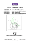
Dash Life
MODULAR OCCUPANT/
ATTENDANT USER GUIDE
______________________________________________________________________________________________
Issue_G May 2013
1
Dash Life
Table of Contents:
Item
Page:
1
Amendment Record
2
2
Important Symbols
3
3
Wheelchair Features / Build Options
4
4
General Warnings
5
5
Intended User
5
6
Important Product Information
6
7
Handling and Stability on Steps and Slopes
12
8
Seat and Posture Belts
13
9
Occupant Controlled Mobility
14
10
Transportation
14
11
Tie Down Information
16
12
Safety Precautions
17
13
Wheelchair Cleaning and Maintenance
18
14
Service Checklist
19
15
16
Useful Addresses
Wheelchair Technical Information
17
Wheel Configuration Chart
19
20 - Single cross brace (Basic)
21 - Single cross brace
22 - Double cross brace
23 - Triple cross brace (Bariatric)
24 - 24” wheel options
25 - 22” wheel options
26 - 315mm wheel options
18
Distributor Stamp / Information
27
IMPORTANT:
DO NOT USE YOUR WHEELCHAIR UNTIL THIS
MANUAL HAS BEEN READ AND UNDERSTOOD.
www.RHealthcarehealthcare.com
Amendment Record:
ISSUE
A
PAGE
21-22
Seat to ground info reversed for ease of reading. Assessment column added
DATE
27.04.2010
B
21-22
Factory setting re assessed; codes altered to suit
17.06.2010
C
19 to 23
& 15
17” model added; and also the 22” version
Rear tie down bracket now orange
13.12.2010
D
Various
23.3.2011
E
20-21-22
& 23
Various
4 & 13
Dash Life, single crossbrace info, E.L.R AND Stump support info,
telescopic seat tube extn info, revised product weights, single piece
footboard info, additional bariatric sizes 18” & 20” added to range.
New side fastening posture belt detailed.
Technical data sheet figures rounded to comply with tender
requirements
Additional Widths Added
Additional Weight Ranges added, 190kg Castors added.
F
G
AMENDMENT
5.7.2011
08/04/2013
14/05/2013
______________________________________________________________________________________________
Issue_G May 2013
2
Dash Life
2.
IMPORTANT SYMBOLS IN THIS MANUAL
THIS SYMBOL WARNS YOU OF A RISK!
This symbol is used to give a warning or caution that is related to the safe use of the
wheelchair. Follow the instructions to avoid personal injury or damage to the product.
This symbol indicates hints and suggestions, which should help make operating the wheelchair
easier and point out any special functions.
This symbol indicates hints and suggestions that should not be carried out while operating the
wheelchair.
This symbol indicates the use of different tools and other adjustments or when service/maintenance
may be required. It should only be carried out by suitably trained or competent persons.
2.1 WHEELCHAIR IDENTIFICATION
Each wheelchair carries a unique identification/serial number that is printed on the serial number label. This label is fitted
on the rear of the wheelchair on the rear cross brace tube (Fig. 1) This label also carries the model code designation,
which includes the wheelchair size and colour. In the event of any queries please have this information to hand if
contacting R Healthcare?
Tie down label
Fig. 1
Label/Decal Placement
placement
1. Dash 4 Life stickers are
situated on the side
panel, 2 per chair, one
on each side of the
chair
2. R Healthcare stickers
are situated on the
front of the side frame
top tube, 2 per chair,
one on each side
frame
Company specific labelling / decals as shown
R Healthcare can be contacted as follows:
R Healthcare, Sheffield Road, Whittington Moor, Chesterfield, Derbyshire, S41 8NJ
Customer services: 0044+ 0870 60 90 600, e-mail: sales@R Healthcarehealthcare.com
Website: http://www.R Healthcarehealthcare.com
CARELESSNESS CAUSES FIRE
2.2. CARLESSNESS CAUSES FIRE
This label shows the position of tie down location points for wheelchair
transport. (See section 6.3 on transportation) This label shows the model
number, serial number, max. User weight and manufacturer details. This
label shows the flame retardency details. The label is fitted to the rear of
the backrest and seat.
2.3. RULES AND REGULATIONS
• The wheelchair is manufactured to meet the requirements of BS EN
12183
• The Upholstery meets the requirements of ISO 7176-16 and the fire and
furnishing regulations SI1324. Other materials wherever possible are
ignition retardant.
Remploy Healthcare Ltd
BS EN ISO 9001 2008 Registered Firm
BATCH DATE
REFERENCE
QUALITY ASSURED
MATERIALS & CONSTRUCTION
to SI 1324 furniture and fire regulations 1988
Outer covering is polymer coated fabric
there is no inner liner
cushion combustion modified polyurethane
foam padded quilting is PVC foam
2.4. MODIFICATIONS AND ALTERATIONS
Making any unauthorised modifications or using none approved
ALL MATERIALS TO APPROVED STANDARDS
parts may change the wheelchair structure and create an unsafe
condition.
______________________________________________________________________________________________
Issue_G May 2013
3
Dash Life
Neither R Healthcare nor your wheelchair provider will accept responsibility for damage caused by
misuse or noncompliance with instructions or advice set out in this manual. Users attempting to use
the wheelchair beyond the manufacturer’s recommendations may put themselves at risk of serious
injury or even death.
3. WHEELCHAIR FEATURES
1.1 DESCRIPTION OF WHEELCHAIR
The Dash 4 Life self-propelling folding wheelchair is fitted with 61cm (24”) diameter wheels and the Dash 4 Life
attendant propelled (transit) wheelchair is fitted with 31cm (12”) diameter wheels.
The standard configuration for the wheelchair is shown below which identifies the key components.
1. Push handle
2. Backrest
3. Armrest
4. Footrest
5. Footplate
6. Front castor
7. Brake
8. Rear Wheel
2. Adjustable Backrest either to
suit 16”, 17”or 18” seat depths
position
3. Rear pivoting; height
adjustable Armrest
1. Foldable Push
Handle
4. In swinging / out
swinging height
adjustable Footrest
8. Adjustable Rear
Wheel. Supplied in either
22”, 24” or 315mm(12”)
7. Adjustable Brake
complete with extending
handle as standard
5. Angle adjustable
Footplate
6. Height and angle
adjustable Front Castor.
Supplied in either 6” or 8”
TWO MODELS AVAILABLE
1. Dash Life
2. Dash Life Bariatric
-
125Kg or 135Kg
170Kg or 190kg
PLEASE REFER TO PRESCRIPTION FORMS FOR REQUIREMENT / OPTIONS
______________________________________________________________________________________________
Issue_G May 2013
4
Dash Life
4. GENERAL WARNINGS
The removal of detachable parts that are supplied either as standard as prescribed or recommended
by the user’s prescriber, healthcare professional or wheelchair dealer, other than for the purpose of
storing or transporting the wheelchair is not recommended and may compromise the correct use of
the wheelchair by the user and the provision of any beneficial effects from the complete equipment.
Take precautions when using your wheelchair to avoid fire risks, such as avoiding smoking or
parking against open fires or heat source.
Do not store your chair in direct sunlight. Direct heat such as sunlight will increase the temperature of
parts on the wheelchair such as the frame or upholstery and they may be hot to touch.
Low temperatures such as frost will have the opposite effect and may make parts of the frame very
cold to touch.
DO NOT hang items such as bags on the back of the push handles, as this can overload the chair and
affect the stability of the wheelchair - causing it to tip over.
DO NOT exceed the occupant weight limit for your chair and do not carry more than one person.
you feel that your body weight may have changed then contact your healthcare specialist.
If
Using a cushion raises the seated position and may reduce the stability of your wheelchair. Some
features and accessories may affect stability. Your healthcare professional can provide guidance on
the stability of your wheelchair and should be consulted when cushions and accessories are being
used.
Your wheelchair should be delivered already assembled. You should remove any packaging before use. If you
have not used a wheelchair or are uncertain about any of the features of your wheelchair then please contact
your healthcare professional, wheelchair dealer or your wheelchair service and ask for assistance. If you have
been informed that you must receive specific instructions about your wheelchair before using it, and then it is
important that you await this instruction for your own safety.
1. Turn the heel loops, if fitted, to the front of the footplate and then flip up the footplates.
2. Grasp the middle of the seat fabric at both front and rear and give a sharp pull upwards. This will part all close the chair.
3. Push both sides together to fold the chair completely. Ensure that the seat is not trapped in the frame when
fully folded.
4. If required, fold the backrest down by pulling up the levers and lowering the push handles.
5. Intended use
Your wheelchair is intended for use in the home, the office, public places and buildings, on pavements, pedestrian
paths and firm surfaces. It is intended to assist with the mobility of the user on the seat and should not be used as a
ladder or as a means of pulling or transporting items, or similar.
Do not use the wheelchair on soft surfaces such as sand, deep snow, slush or mud as this may affect
the stability.
Care should be exercised when using the wheelchair on wet or slippery surfaces such as wet cobbles
or icy pavements, as these may cause the wheels to slip or may cause carers/attendants controlling the
wheelchair to slip.
Using your wheelchair during darkness or in poorly lit areas.
When using your wheelchair during darkness or in poorly lit areas, then consideration should be given to the
use of high visibility markers or reflectors that can be fitted to the wheelchair or the use of high
visibility/reflective clothing such as fluorescent waistcoats, belts or armbands, particularly in poorly lit areas or
when crossing the road.
Maximum safe slope
The maximum safe slope for this wheelchair is 8 degrees. (This represents a slope of approx 1 in 6).
See further notes and guidance in section 4.7 on wheelchair stability.
Users, carers and attendants attempting to use the wheelchair beyond the manufacturer’s
recommendations may put themselves at risk of serious injury or even death.
______________________________________________________________________________________________
Issue_G May 2013
5
Dash Life
6. IMPORTANT INFORMATION
INTRODUCTION
The type of wheelchair, and attachment features,
provided will be different according to individual user
requirements, and clinical assessment of need. In
many cases the result will be a compromise solution.
Some modular wheelchairs can be set up or finely
adjusted to suit user needs. Users should contact
their approved distributor if they are having problem
in using their wheelchair, a simple adjustment or
alternative build configuration may help to resolve the
problem.
R Healthcare manual wheelchairs can be divided into
two broad categories.
•
•
Attendant Propelled (315mm (12” wheel)
Occupant Propelled (22” or 24” wheel)
This general information section covers safety issues
of wheelchair use covering all of these.
Please read carefully together with all other
information provided, covering the specific model
supplied, which will give particular details of the
wheelchair features and construction, methods of
operation and correct setting methods.
6.1 GETTING IN AND OUT OF A WHEELCHAIR
FACING FORWARDS
For maximum safety, these operations should be
carried out with the help of an attendant. The
occupant should always try to assist the attendant
wherever possible to share the total effort.
Carers should not attempt to lift without help.
If this is not possible a hoist may be required.
Getting into the wheelchair.
Make sure that the brakes are on, flip up the
footplates, taking care that the heel support straps (if
fitted) are not jammed against the footrest support
frame. On some models, footrests may be detached
or swung away for easier access.
Note that when footrests are detached, the
mounting swivels remain exposed and care
should be taken to avoid the occupant
catching these accidentally.
Getting out of the wheelchair.
Make sure that the brakes are on, then flip up the
footrests or detach them. The occupant should place a
hand on each armrest, bend slightly forward and place
both feet well back.
6.2 SIDE TRANSFER
When the wheelchair armrest is removed, it will allow
sideways entry to the chair and vice versa, from another
Physically active
chair or car seat. See fig 3.
Independent users with upper body and arm strength
should eventually develop
skill to carry out this
manoeuvre without help.
However, it is advisable that
an attendant should be
available
if
assistance
becomes necessary.
Make sure the brakes are
on, or that the wheelchair is
prevented from moving, It is
easier to transfer when flip
up
footrest assemblies are swung back out of the way,
or removed so as not to interfere with the legs. Feet
should be firmly on the ground and not on the footrest.
The safest way to transfer is to bend slightly forward.
If there is a gap between the two seat surfaces, it may
help to slide along a smooth transfer board, or to use
some other lever point such as a car hand grip for
additional support whilst manoeuvring from one seat to
the other.
DO NOT ATTEMPT SIDE TRANSFER ON
SLIPPERY OR UNEVEN FLOORS
Fig 2 - Getting
in/out of the wheelchair
The occupant may be able to help by pushing on the
armrests to provide support whilst being lowered into
the seat. Finally, push the footplates down, and
locate the occupant’s feet on them. see fig 2.
______________________________________________________________________________________________
Issue_G May 2013
6
Dash Life
Fig 3 – Side Transfer
6.4 PUSHING TECHNIQUES
Pushing a wheelchair with a helpful occupant can be an
enjoyment for both people involved provided that there
is mutual confidence and understanding.
When first planning a trip, the pusher should check the
distance and terrain to be covered, bearing in mind that
a slope going out is a hill coming back. A combination
of slope and camber is common in many areas. Try the
chair out on typical surface conditions nearby, and
practice manoeuvres likely to be encountered on a
longer trip.
Fig 4 – Maintain a firm
grip on the push handles
The pusher should be familiar with the operation of the
wheelchair, remembering to put the brakes on and
steady the chair before the occupant gets in and out.
Where applicable, detachable features such as push
handles and armrests should be checked for security,
before setting out on a journey. The occupant should
not be rushed during transferring in and out of the
chair.
Before setting off, the pusher should make sure that the
occupant is comfortable and that clothes, rugs, covers
etc do not catch in the wheels or interfere with the
general workings of the wheelchair.
Fig 5 – Attendant Control
6.3 BRAKES
Hand brakes are provided for preventing wheel
movement when parked, particularly on a slope, or
during occupant transfer to and from the wheelchair.
The action of a brake shoe pressing on the tyre makes
correct inflation pressure important.
Cable operated attendant brakes are an option
available for mounting on the push handles to allow the
attendant to control the chair without having to reach
down for the hand brake handle. These may also
provide the attendant with a means of controlling the
speed of a wheelchair when going downhill, and are a
safety improvement on slopes and undulating terrain,
as described in Technical Information Manual (Part B).
Operating the wheelchair in this way however,
demands that the attendant is skilled in the controlling
operation, as a sudden change in direction will result if
one wheel is retarded in advance of the other.
Brake adjustment— Loosen sideframe brake bracket
clamp, and drop brake sub assembly until there is a
5mm gap between the brake and the tyre while in the
brake is in the off position. Tighten and secure to
10ft/lbs ensuring tyre is central to the brake shoe.
The pusher should walk at a sensible speed, and tell
the occupant before changing position, tipping the chair
or manoeuvring, also paying attention to the surface
conditions and avoiding uneven or soft ground
wherever possible.
The pusher should always maintain a firm grip on the
push handles. The chair should not be jolted or jarred,
or rocked like a pram. See figs 4 & 5.
Shopping bags or other additional heavy loads
should not be carried in a wheelchair unless
specifically designed for the purpose. This
particularly applies to hanging items over the
push handles, which can overload the chair and
affect stability resulting in injury if the occupant
tips out of the chair when it is left unattended
momentarily.
Fig 6 – Going down a kerb
Start position
Images showing extending brake handle
______________________________________________________________________________________________
Issue_G May 2013
7
Dash Life
Make sure that the front end of the chair is
lowered slowly to the floor, and that the
castors are pointing to the rear.
Fig 7 – Going down a kerb
Finish position
The chair footplates, or occupant feet if longer,
should be taken to just in front of the kerb edge.
The pusher should hold the chair handles firmly,
pressing down on the tipping lever, tilting the chair
backwards using body weight leverage, bringing
chair forward till the back wheels touch the kerb.
The front castors wheels can then be lowered down
onto the path, making sure that the wheels are
facing rearwards. With the push handles held firmly
the attendant should now lift and push the chair.
Castors with small
wheels are more
liable to dig in,
than large wheels,
and require extra
care in use.
6.5
Going up a kerb. First method.
Going up a kerb. Second method.
The chair should be turned round so that the back
wheels are against the kerb and the attendant
should hold the pushing handles firmly and tip the
chair backwards.
KERBS
Negotiating a kerb.
The methods described here involve an attendant
controlling the operation. Active users adopt balancing
techniques carry out kerb manoeuvres independently,
but methods will vary according to the setting of the
chair, the physical strength of the user and skills
acquired through training and practice with wheelchair
experts. See section 1.6.
Using body weight as leverage the attendant
should then pull the chair off the kerb and up onto
the pavement, making sure, as above that the
castor wheels are facing rearwards.
The chair may then be pivoted to face the direction
of travel and pushed forward.
Going down a kerb:
The chair castors should be taken to the edge of the
kerb. The pusher should hold the chair handles firmly,
pressing down on the tipping lever and at the same
time tilting the chair back. See fig 6 & 7.
The rear wheels can then be taken to the kerb edge
and the foot removed from the tipping lever. The chair
is then lowered down the kerb on its rear wheels, with
the castor wheels facing rearwards, this prevents them
jamming up momentarily as the chair starts to move,
before pivoting the chair gently to the ground, to face
direction of travel and then pushing forward.
Fig 8 – Apply pressure to
release and engage push
handle as per above.
Ensure that push handle
locks are fully engaged
before using the chair.
Fig 9 – Going down/up a flight of steps
Note: The chair must not be tipped for
ward or the occupant may fall out.
When stabilisers have been fitted, this
operation is more difficult to control,
and extra care should be taken.
______________________________________________________________________________________________
Issue_G May 2013
8
Dash Life
6.6
Wheel Mounting Bracket.
The image below shows show how the wheel mounting
block is fitted to the chair and how it can be
reconfigured by repositioning it through the alignment
of the available holes in both the slide moulding and the
side frame
R Healthcare recommends that trained
personnel configure the chair and
carry out necessary adjustments
following professional assessment.
Always ensure that the quick release wheels
are fully engaged with the locking ball
bearings on the axle shaft fully engaged
and visible on the inner side of the axle bush.
Never mount the quick release rear axles with
the release button positioned inside the
frame. This will cause the wheels to release
when the chair is folded.
Do not alter the position of the wheels in the
wheel mounting blocks without the approval
of the person prescribing the wheelchair.
6.7 FOOTREST
Wheel Assembly.
Correct positioning of the footrests to suit occupant
size and position is very important as it has a major
effect on distribution of seating pressure. The
underside of the occupant’s legs should be supported
as far forward as possible over the length of the seat,
to reduce high-pressure areas. When transferring to
and from the wheelchair, avoid contact and weight on
the footrest, as this will cause the wheelchair to tip
forwards.
Fig 10
WHEEL CONFIGURATION CHART
DETAILED ON PAGES 23, 24 & 25
OF THIS MANUAL
To detach the footrest
assembly: Pull the lever
’a’ sideways and swing
the footrest inwards or
outwards and lift out of
the frame. To attach the
footrest assembly: Locate
the footrest in the front
frame and swing it round
to the centre of the
wheelchair until it locks
securely into position.
‘a’
Keep fingers and other
items away from the
footrest attachment
assembly when it is being
Fig 11 – Quick release
button release
Quick release self - propelling wheels
Your wheelchair may be fitted with quick release
wheels; either 22” or 24”. Quick release wheels can be
removed from the wheelchair to make it lighter for lifting
and easier to store. To remove wheel: Press the button
(1) in the centre of the wheel and slide the axle and
wheel out of the axle bush fully see fig 11. To replace
wheels: Reverse the above procedure and depress the
centre button of the axle and push the exposed axle
into the wheel bush. When the axle/wheels are fully
inserted, release the centre button.
Make sure that the button is fully released
and that the wheel is secure in the axle bush
by pulling the wheel gently away from the
wheelchair. The wheel should remain in the
same place.
6.8 FOOTPLATE ADJUSTMENT
Both the height and the angle of the footplate are
adjustable.
Tools required: 4mm & 5mm Allen Keys
Fig 12 – Angle and
eight adjustable
footrest assembly
– exploded view
Non angle
adjustable as used
on our Dash 4 Life
Basic model
Height and angle
adjustable option
______________________________________________________________________________________________
Issue_G May 2013
9
Dash Life
6.11
ONE PIECE FOOTBOARD
A one piece footboard is
available across all sizes of
the Dash 4 Life range; 15” »
24”. The footboard is supplied
complete with purpose made
swingers. These fit onto the
existing attachments on the
front tube of the wheelchair
6.9
ARMRESTS
Lightweight Armrest
This version is supplied as standard on the model D4L
Basic; however; it is available as an option on all other
models
STABILIZERS
Stabilizers can be fitted if there is a risk of the user
tipping the chair backwards. Their position affects the
angle that the chair can tip back to before it touches the
ground. R Healthcare recommends that trained
personnel configure the chair and carry out necessary
adjustments following professional assessment prior to
use
The armrests are both removable, height adjustable and
they also pivot fully to allow for transfer.
Adjusting the stabilizers can adversely affect
the performance of the wheelchair.
6.10
BACKREST
Fig 14
The backrest can be configured in two optional settings;
front and back. This allows the seat depth to alter
between 16”, 17” and 18”. See fig 13. The angle of the
backrest can not be altered unless the chair is of the
reclining type. However there are four options of
backrest angle that can be purchased; 0º, 5º, 10º 15°&
20º
6.12
CROSS BRACE ASSEMBLY
There are eleven options of cross brace width ranging from
12” through to 24”. All weight and dimensional information
is detailed within the Technical data sheets ref pages 20,
21 & 22 of this document.
The scope of the Dash 4 Life in terms of weight of occupant
runs as follows.
Single Cross Brace
– 125Kg maximum user weight
Double cross brace – 135Kg maximum user weight
A full options configuration chart is available on pages
23, 24 & 25Tools
of this
document
required
– 4mm Alan Key, 10mm
spanner
A reclining version of the Dash
4 Life is available in
Fig 13
all widths.
Backrest angle adjustment – Adjust the angle of the
backrest by using the pull hand lever (a)
Triple cross brace (Bariatric) – 170Kg & 190kg max user
weight
Tools Required – 4mm Allan Key,
10mm spanner and a soft hammer
Double cross
brace shown
above See fig 15
‘a’
Backrest brace bar is available as an option to be fitted
to any size or configuration of chair.
2 x 4mm
screws attach
the brace bar to
2 x nut-serted
holes in the
upper backrest
tube
Fig 15
Remploy recommends that trained
personnel configure the chair and
carry out necessary adjustments
following professional assessment.
______________________________________________________________________________________________
Issue_G May 2013
10
Dash Life
6.13
CASTORS
Fig 16 – Castor
assembly –
exploded view
There are three height
options on the castor
assembly as well as a
choice of two castor wheel
sizes; 6” and 8”. There are
two weight capacity’s, up to
170kg and up to 190kg. All
options and configurations
are detailed in the technical
data sheets at the end of
this document
6.15 STUMP SUPPORT
Originally developed for post operative below knee
amputee care where keeping the stump horizontal
improves the natural healing process. This support
also provides a comfortable long term option for
some amputees who may continue to use a
wheelchair for mobility, in some circumstances.
The R Healthcare Stump Support fits into the front
Frame footrest swivel brackets.
6.14 ELEVATING LEGREST
When these are fitted to a wheelchair, they provide
support to the underside of the user’s calf, at a range of
angular positions.
They fit into the top of the front tube; latching into the
cast bracket; also on the front tube of the wheelchair,
and can be released and swung away or removed during
side transfer or other manoeuvres in the same way as
the standard Dash 4 Life type footrest.
The support pad is on a height adjustable stem.
Adjustment however should only be carried out
by an authorised professional who understands the
clinical requirements.
Users and occupants should note that leg and
stump supports should not be used as seat
extensions, or occupant transfer support.
chair.
6.17
The calf support pad can be swivelled through 90
degrees for sideways folding of the wheelchair. Users or
carers should ensure that the locking latch is fully
engaged the when refitting the Legrest or any similar
adaptation prior to use.
Angular calf support adjustment is by means of a sprung
release trigger, which locks along a fixing bar at any
preferred position within the adjustment range.
Operation of this requires a degree of finger strength,
and it is recommended that this is carried out by a carer
if required. Users are reminded that when the Elevating
Legrest is adjusted to a high position, the swing away
action requires greater space.
Alan Key (4mm) adjustable clinching feature to adjust
footrest height is located at the end of the bracket.
Note that the fitting and position of the Elevating Legrest
can alter the balance of the chair. This is particularly
significant when the Legrest is fully extended, and
supporting a large heavy limb. In this position, weight
distribution may be such that the wheelchair is balanced
towards the front wheels, with the rear wheels taking
only a nominal weight. This affects general chair control
and also effectiveness of brakes.
When weight is on the front wheels, control of
the wheelchair in an outdoor environment
particularly going downhill can become
impossible, and this should always be avoided.
Telescopic Seat Tube Extensions
The above kit can be used to extend the standard
16” deep seat canvas to achieve 18”. Two separate
kits are available; these being 17” deep seat (1”
extension) or an 18” deep seat (2” extension. The
tubes supplied are inserted into the rear of the seat
tube; and then the seat canvas extension fitted
Remploy recommends that trained
personnel configure the chair and
carry out necessary adjustments
following professional assessment.
______________________________________________________________________________________________
Issue_G May 2013
11
Dash Life
6.18 Backrest Extensions
6.19
These are available in a range of height and width
sizes, and are made for fitting into the upper backrest
Frame of all the above models using an adaptor kit.
The backrest extension itself comprises a pair of
straight tubes to which a supporting canvas to suit the
required chair width is secured by fixing screws to the
face of the tubes, in the same manner that the seat
canvas is secured to the chair Frame.
The backrest adaptation kit has two bobbins for each
side which should be screwed into the insert points in
the outside of the Frame. These bobbins remain a
permanent feature on the chair Frame to facilitate
location of the backrest extension by means of the
keyhole slots, which are cut into the inside face of
each extension tube.
Tray
The Dash 4 Life has a retrofitable tray which is
attached by using the tray brackets supplied.
When fitting adaptations such as these,
we advise that the user and carer are made
aware of the circumstances of intended use when
the attachment must be removed. This would
certainly be necessary in occupant transportation
in a vehicle, and removal may be required during
other outdoor activity where there is an adverse
effect on performance e.g. stability on sloping
ground, or climatic effects.
HEIGHT ADJUSTABLE PUSH HANDLE
The keyhole slot feature allows easy assembly of the
backrest extension or removal for storage of the chair
by the attendant or carer. When the chair is fully open,
the tension in the supporting canvas makes removal of
the extension difficult, and when fitting or removing the
extension, the chair
should be in the
closed position.
DETAIL OF BOBBINS AND
KEYHOLE SLOTS
R Healthcare recommends that trained
personnel configure the chair and
carry out necessary adjustments
following professional assessment.
2 x quick released
pins used to secure
height and depth
adjustment
The Height Adjustable Push Handle is designed
for use on the model Dash 4 Life. It allows for the
increase of both the height and depth of the push
handle. The height adjustable push handle
replaces the existing push handle on the chair
and is available as spare. The tube-work attaches
to the existing plastic pivot moulding on the side
frames. The existing single fastening is used to re
attach the assembly. The push handle can be
used in any application the non-adjustable push
handle can be used in but it also means that when
used with a power pack the push handle can be
extended to allow a greater distance between the
attendant and the chair to allow for a more normal
stride pattern. The adjustable push handle will
also be useful for tall attendants who currently
have to bend excessively.
R Healthcare recommends that trained
personnel configure the chair and
carry out necessary adjustments
following professional assessment.
______________________________________________________________________________________________
Issue_G May 2013
12
Dash Life
7.
HANDLING & STABILITY ON STEPS & SLOPES
DO NOT ATTEMPT SIDE TRANSFER ON
SLIPPERY OR UNEVEN FLOORS
A little forward planning can eliminate difficult
manoeuvres such as steps. Modern public buildings
should provide permanent wheelchair ramps, with a
practical slope angle, built according to regulations, for
safe access.
Technical Test data on stability of wheelchairs should be
seen as a tool for comparison. Data does not convey
actual feel of the wheelchair in the intended
environment. Initial supervised user training and
assessment by a rehabilitation professional, with the
wheelchair in the intended usage environment is
recommended, and users should ensure that they are
confident with regard to this aspect of use.
An important factor in considering accessibility and
slopes is the effort demanded from the occupant or
attendant using the chair (attendant brakes are an
available option). Pushing up a steep slope which
extends over a distance, may create a need to stop and
rest, which in turn demands additional and undesirable
effort to start back upwards again. Stopping a
wheelchair on a steep downward slope also demands
effort and control, and surface conditions need to be
taken into account when deciding what outdoor route to
take. Manoeuvres, which demand over exertion, may
create risk of injury to the user and should be avoided.
However, if in temporary difficulty, wheelchair users
should not hesitate in asking for assistance from people
nearby, someone will usually be happy to help.
Modern buildings should have slopes built to a required
standard angle, but this is not the case with all access
areas. Learning the geography of an area is important.
As an all round guide, a maximum safe slope of 8
degrees is our recommendation for the R Healthcare
range of manually propelled wheelchairs. However this
recommendation may need to be changed if the
wheelchair has attachments added to it, such as an
elevating legrest or carry bag, which adversely affects
stability. Such changes to the chair specification may
have a critical effect, and they require re-assessment by
rehabilitation professional.
SAFE SLOPE OF 8 DEGREES FOR MANUAL
WHEELCHAIRS, DYNAMIC STABILITY ON PAGES
23, 24 & 25
Where possible, the hazard of negotiating steps should
be avoided. Many falls and injuries to both occupant and
helper can occur when inexperienced people are
carrying out this operation, and if users or carers are
concerned about a particular hazard in the usage
environment, which they must regularly overcome, they
should consult their wheelchair rehabilitation service, or
community services department, as appropriate.
There may still be occasions when steps must be
negotiated. In the event of the chair having detachable
pushing handles, these should be checked for security
in the locked position before attempting this
manoeuvre. Stabilisers may require removal if they
interfere with the chair balance angle on a flight of
steps. This should first be checked out with an
unoccupied chair.
Two attendants at least are required for this operation.
The attendant supporting the main load should grip the
chair at the push handles, and repeat the procedure as
section 2.6 for getting down a kerb at each step, the
second attendant at the front will be required to guiding
the footrest area, and provide reassurance to the
occupant. A third person could act as guide for the
chair team if the steps are high.
Reverse this
procedure for going up a flight of steps, with the
attendant supporting the main load at the push handles
pulling, and the second attendant at the front guiding
the chair using the corner of each side frame.
Specialist training for very experienced users to
negotiate a flight of stairs independently is available,
but this is beyond the context of this guide.
8.
SEATBELTS (ALSO POSTURE BELTS)
The fitting of these should be considered in all
circumstances where the chair is used outdoors, over a
sloping surface or kerbs. Belts normally secure the
occupant by means of a quick release buckle in the
centre. In cases where the seatbelt is part of the
postural/ clinically assessed needs, provision of a
seatbelt will be covered by a clinical assessment.
A basic security seat belt may become required after a
period of use, if the environment or method of use
changes, or where the occupant feels a need for
greater security in the wheelchair. These can be fitted
retrospectively by a fully trained and competent
technician, but if unable to utilise any of these
instructions, contact either your NHS rehabilitation
engineer or the manufacturer of the wheelchair.
A correctly fitted posture belt should fit over a user’s
pelvis at approximately 45 degrees from the anchor
without obstruction from any part of the wheelchair (e.g.
skirt guard or armrest). The posture belt should be
adjusted so as to fit snugly around the user’s pelvis to
provide an appropriate sitting position. The adjustment
of the belt must be carried out by a competent person
who is able to assess the client’s needs and frequency
of checking of the belt adjustment.
Future reviews of an individuals needs should include
consideration of the appropriateness of the posture belt
and its method of adjustment, fastening and release
especially where a users’ or carers’ capabilities change
over time.
______________________________________________________________________________________________
Issue_G May 2013
13
Dash Life
Lengthening or shortening, is affected by slackening
and adjusting the webbing, as it passes through the
male part of the fastener until the desired fit is obtained.
This adjustment covers the Loop style Lapbelt (Fig
17a); the two piece style Lapbelt offers more
adjustment options by able to alter to belt from both
right and left hand sides using the integral slider (Fig
17b). When adjusted ensure the webbing is tightened,
the buckle is located centrally, and the surplus webbing
is secured by the tri-glide provided.
Inspection and maintenance of posture belts and their
fittings should be included within the planned
preventative maintenance programme for the
wheelchair.
Wheelchair seatbelts are not tested to meet the crash
test standards required for occupant restraint in a
vehicle, but we advise that they should remain in
position during a journey to provide occupant security,
and support during normal traffic movements of
sideways cornering and speed changes.
Side Fastening
Style Lapbelt
Fig 17b
Side fastening posture belt fastening; the brackets of the
belt are secured via the existing bolt / nut configuration
that affixes the wheel mounting bracket to the side frame.
Transportation, crash tested restraints for both
wheelchair and occupant are part of the actual vehicle
equipment, and must be secured to the vehicle itself,
as shown in Fig.18
N.B. The Posture Belt (Fig 17b) affixes
direct to the side frame as per photo using
existing fastenings.
Fig 18
Clean if required, using a damp cloth with a small
amount of washing up liquid. Rinse with a clean damp
cloth.
Preferred Zone
Loop Style
Lapbelt
WARNING – DO NOT disassemble, shorten,
cut or drill this retaining belt, it could seriously
compromise the belts integrity and invalidate
any manufacturers warranty.
______________________________________________________________________________________________
Issue_G May 2013
14
Dash Life
9.
OCCUPANT CONTROLLED MOBILITY
Handrims
These are provided for the occupant to grip and push
round to propel the wheels. Best results will be
obtained by a long pushing stroke, which gives a
continuous and smooth forward motion. Many users
find that gripping across the tyre and handrim at the
same time gives better control. We recommend that
when operating in this way, wheelchair gloves are
worn.
STABILISERS ARE FOR OCCUPANT
SAFETY. THEY SHOULD NOT BE
REMOVED UNTIL THE USER IS ABLE
TO DEAL WITH BACKWARD FALLS
AND TIP OUTS
If stabilisers are removed for ascending or
descending a flight of steps additional carers and
handlers should be present, and they should be
refitted when the manoeuvre has been completed.
Users with gripping difficulties may find larger section
or Capstan types, with easy grip features, more
practical.
When using a handrim to turn a chair round in a tight
space, push one wheel forward, whilst pulling the
other wheel backwards. Always make sure when
carrying out this manoeuvre, that there are no
obstructions or bystanders in the turning space
required.
Balance Training
Physically active, independent people require
wheelchairs, which allow them to safely negotiate
kerbs
and
achieve
efficient
control
and
manoeuvrability.
It can be hazardous for an occupant to attempt
wheelie positions on wheelchairs, which are stable
above 10 degrees rearwards static stability, as
physical effort needed to manoeuvre and pull a
wheelie can be excessive, consequently increasing
the risk of accidentally tipping over backwards.
Maximum efficiency of hand propulsion occurs when
occupant centre of gravity and wheel centre coincide,
and is dependent on the occupant shape and size.
Physically active people should have wheelchairs
with fine wheel position balance settings, i.e. below
10 degrees rearward stability. These chairs should
have rear stabilisers when supplied to inexperienced
users, allowing the user to practice balancing
techniques with the reassurance that the chair will not
accidentally tip over backwards.
During training, the Therapist, or Training Supervisor
can therefore build up the confidence of the occupant
in stages, by initially setting the wheelchair up in a
safe balance position, with the stabilisers acting
positively, and progressing gradually towards
optimum performance settings, with the stabilisers
only acting as a back up.
Once satisfied that the occupant has developed the
full range of wheelchair skills, and provided that the
medical condition is not compromised, the therapist
can authorise removal of the stabilisers, and the
occupant then takes full responsibility and control of
the wheelchair.
Outdoor Safety Hints
Most pavements slope slightly towards the kerb
and the wheelchair may have a tendency to
pull towards the road. Occupant controlled
Active User wheelchairs with cambered wheel
setting reduce this tendency.
The fitting of polyurethane tyres eliminates punctures,
and provides reassurance of not being stranded
some distance from a service centre, but the use of
these tyres imposes a harder ride and the wheels
must be checked more frequently, to ensure that
there is no deterioration of spoke tension and
security. Polyurethane tyres have slightly less grip
than pneumatic tyres; therefore, self propelled chairs
fitted with polyurethane tyres are also fitted with a
high friction brake shoe grip.
When out at night, ensure that both you and your
wheelchair are visible, consider both clothing, and
light reflective trim features.
10.
TRANSPORTATION
Wherever possible it is recommended that wheelchair
occupants transfer to a vehicle seat during a journey,
with the wheelchair securely stored separately in a
purpose made storage area.
Stowing the wheelchair in a car boot
The folded chair should be placed close to the
car boot with armrests, footrests and other
removable parts detached to split total weight
into component form. Wheelchairs with
detachable wheels reduce the weight for lifting.
The person stowing the chair should grip
convenient fixed parts of the chair, and lift
keeping
the
back
straight, bending from
the hips and knees. If
in any doubt about
handling the weight,
assistance should be
sought.
______________________________________________________________________________________________
Issue_G May 2013
15
Dash Life
Car Driver Information
Physically active wheelchair users can drive cars and
store the wheelchair in the car independently, with a
lot of practice. Training at specialist driving centres is
recommended. Two door cars provide the greatest
access space. Gaining entry to the car first involves
side transfer as section 3. When carrying this
manoeuvre wheelchair users should chose a position
where there is no risk of interference from other
traffic.
The stored wheelchair requires locating not only so
that the driver can reach it, but also to remain safely
secured during the journey.
With sideways folding wheelchairs the driver should
pull the folded wheelchair into the vehicle into space
behind driver or passenger seat. see figs 19 &20.
Fixed frame wheelchairs, with quickly detachable
wheels can be disassembled once the driver has
transferred into the car. The parts then being stored
safely within the vehicle.
It is recommended that wheelchairs stored on the
front passenger seat are secured using the car seat
belt through the frame. A wheel bag may be useful
for long journeys or for keeping dirt away from the car
seating area. When there is another able bodied
passenger present, the storing options as section 9.1
are recommended.
FIG 19
A Sideways
Folding
wheelchair can be
stored behind the
front seat.
FIG 20
Guidelines for Wheelchair & Occupant
Transportation in Vehicles
This information is given in order to reduce the risk of
bad practice. It is based on current available
knowledge.
Wheelchair users and transport
operators have a responsibility to ensure that safety
measures take account the needs of wheelchair
occupants and other passengers to minimise the
risks involved for each individual situation. Vehicles
transporting wheelchair occupants should have safe,
secure wheelchair access, transport operators should
recognise this. Available publications are Safe
Transportation of Wheelchairs, DB2001(03) June
2001, Safe Use of Wheelchairs and Vehicle mounted
Passenger Lifts. DB2003(03).
Public Transport
Wheelchair users who choose to travel in a local bus
or public service vehicle should recognise that this
involves risk, and a complexity of related issues. The
user has a responsibility to make the decision of how
to travel carefully. Pre journey planning will avoid
difficult access situations, which could be
encountered later, when it is too late to do anything
about it. In busy, congested areas, users will require
skill to avoid collisions with other passengers, when
approaching and boarding the vehicle. Wheelchair
brakes may not hold a chair and occupant stable
against inertia forces of normal traffic conditions,
such as cornering or coming to a halt, and
wheelchairs in vehicles should be prevented from
moving by other means. Dept of Transport approved
designated wheelchair areas in low floor buses with
support pillars and hand rails at wheelchair height are
the most suitable. Users are advised to check
availability of wheelchair facilities with the transport
vehicle operator, and note time schedules.
Specialised Transport for Wheelchair Occupants.
These vehicles should be fitted with approved
restraint systems. Dept of Transport approved taxis
for individuals are available, but users with neck
problems are advised to check that there is adequate
headroom.
Restraint systems for minibuses range from
wheelchair tie downs, to more compact foldaway
devices. Installers and operators of vehicles with
restraint systems must be trained in their correct use
by the restraint manufacturer, or approved mobility
specialist. The CTA can provide useful advice. R
Healthcare have actively participated in the creation
of new safety standards in this area through
membership of BSTA, in co-operation with the Dept
of Transport & B.S I. The resultant standard, BS EN
ISO 10542 states the following:
______________________________________________________________________________________________
Issue_G May 2013
16
Dash Life
The wheelchair must be secured to the floor by a restraint system,
preferably in line with direction of travel. The wheelchair should not be
occupied by more than one person. Fittings such as trays should be
stowed separately. Wheelchairs used for transportation of occupants in
vehicles should have a full height backrest of at least 415 mm for adults,
head supports are recommended.
11.
TIE DOWN PROCEDURE
R Healthcare recommend Unwin Tie Down and Occupant Restraints.
Unwin’s provide in depth training courses for the application of their
products which meet the ISO 10542 standards, and have a proven test
record with the R Healthcare wheelchair range.
Through the
armrest and
over the side
frame.
We recommend that persons responsible for securing wheelchairs in
vehicles attend an Unwin training course, or any other informative training
applicable to the usage environment.
Restraint systems should only be fitted in specially adapted vehicles,
where the structure has been strengthened to take wheelchair location
points. Details of Unwin systems we have tested are as follows. There are
similar products available from other suppliers, which we know, have also
been tested satisfactorily, and if used these should be applied as per the
supplier’s recommendation.
Tie Down Point labels on all R Healthcare supplied chairs indicate the correct
position to attach karabiner type chair restraints. Continuous product improvement
has resulted in new design chairs having specific tie down karabiner locations to
enable correct and easy attachment by the transport operator.
The following reference covers Unwin chair restraints only.
WHEELCHAIR RESTRAINT TYPE UNWIN PART NO.
DASH 4 LIFE 4 Point Webbing with Karabiner W120
The model Dash 4 Life has been crashed tested successfully to ISO
7176-19 which is for forward facing with tie downs.
Wheelchair Seat Belts and Posture Belts are not crash tested
restraints, although they help keep an occupant in a preferred
position during normal vehicle motion. To meet crash safety
standards, wheelchair and occupant must be secured to the vehicle
independently. The occupant restraint should be secured directly to
the vehicle at a point above shoulder height. No component of a
wheelchair restraint should pass through the wheels. Wheelchair
restraints should secure the wheelchair in such a manner that they
cannot become free if chair components deform, or if one or more
tyres deflate. Under no circumstances should wheelchairs be
modified or strained to allow installation of clamps or fittings.
The side-view projected
angle for the rear tiedown
straps is between 30°and
40° from the horizontal.
The side-view
projected angle for the
front tiedown straps is
between 40° and 60
Rear Tie Down Bracket
Colour - Orange
The rear-view
projected angle of
the rear tiedown
straps is within 10°
of the wheelchair
reference plane.
The front-view projected
angle of the front tiedown
straps is within 25° of the
wheelchair reference plane,
but angled so as to provide
some lateral stability to the
wheelchair.
______________________________________________________________________________________________
Issue_G May 2013
17
Dash Life
12.
FIRE PRECAUTIONS
When using the chair, both indoors and outside, always take precautions against fire risks. Avoid smoking, and
do not park the wheelchair against an open fire, or intense heat source. Bear in mind that the temperatures
reached in a hatchback car on a hot day can cause stored wheelchair component parts to become too hot to
handle. When parking, the pusher should position the chair so that the occupant can see and communicate as
well as possible. In buildings check that fire exits and procedures are understood.
DISABLED PERSONS ARE AT GREATER RISK THAN OTHERS IN THE EVENT OF A FIRE.
THE ENVIRONMENT IN WHICH A WHEELCHAIR IS USED SHOULD INCORPORATE SAFETY
PRECAUTIONS TO MINIMISE FIRE RISK TO WHEELCHAIR OCCUPANTS
GENERAL PRECAUTIONS & INFORMATION
Warranty
R Healthcare guarantees the products supplied to be free from manufacturing defects, and will replace
components where necessary free of charge, for a period of 24 months from the date of purchase as long as
the product has not been deemed to have been subject to miss-use. This guarantee is subject to the condition
that the product has been used, adjusted and maintained in accordance with the user and maintenance
instructions supplied by R Healthcare.
This does not affect your statutory rights. A more complete warranty statement is available on request from
Authorised Distributor or Disablement Service Centre.
The recommended lifetime of the model Dash 4 Life is Five years from purchase date.
Service
Service Records should be completed by the Authorised Distributor Servicing Department and retained by the
user as a reference. Service checks should be carried out by the Authorised Distributor at the recommended
interval specified on the Service Record. Batch code and serial numbers are essential for the specification of
spare parts. If in doubt, your Authorised Dealer or Rehabilitation Specialist will be able to provide help and
professional advice on correct and safe use of wheelchairs. There are also many national and local
organisations, which will be pleased to provide help and advice for wheelchair users.
All R Healthcare wheelchairs are designed with the needs of disabled people in mind. We hope that our
wheelchairs provide their users with the reliability, freedom or independence they need for a more improved
lifestyle.
R Healthcare Group has a policy of constant product improvement and reserves the right to change
specifications without prior notice.
This guide contains information of a general nature. All models and attachments have specific features and
will have additional information provided showing correct operation method.
UNAUTHORISED WHEELCHAIR MODIFICATIONS MAKE THIS WARRANTY VOID.
R HEALTHCARE ARE NOT RESPONSIBLE FOR ANY ACCIDENT RESULTING FROM
SUCH UNAUTHORISED MODIFICATIONS.
______________________________________________________________________________________________
Issue_G May 2013
18
Dash Life
13.
LOOKING AFTER YOUR WHEELCHAIR - GENERAL CARE AND MAINTENANCE
READ ALL INFORMATION PROVIDED BEFORE ATTEMPTING TO USE
Users should not attempt major repairs or modifications. Approved Distributors have full Service Information
and are able to advise if the chair becomes damaged, requiring major part replacement, or refitting. If in any
doubt about service requirements, contact the Approved Distributor. The R Healthcare Customer Services
Dept is also available for more information The Service Record included with this Information Guide, has
details of model references to be quoted when Service Information is requested.
Frequency of distributor service maintenance depends on usage level. We recommend that chairs are
checked by the distributor at assessed intervals, according to the level of use and usage environment.
Warranty can be affected if a wheelchair is not adequately maintained.
Users should note that wheelchairs retain appearance if looked after and cleaned regularly, referring to the
list below for routine maintenance and safety checks, which they are responsible for.
Information received from upholstery manufacturer
The fabric used for wheelchair upholstery is easily cleaned in-situ. However, as there are some substances
which may affect the material, careful attention to REGULAR cleaning will not only prolong its life but will
ensure that its appearance is maintained.
Resistance to stains and chemicals
The upholstery is resistant to most mild acids, alkalis and household stains. Some substances such as ballpoint pen ink, lipstick, newsprint and food colourings may be absorbed by the vinyl and cause permanent
staining. This can often be minimised by immediate cleaning with a damp, soapy cloth or sponge
Cleaning
To maintain its appearance, the fabric should be cleaned REGULARLY to remove fatty substances in soiling,
which may reduce its service life. Light soiling can be removed by adding a small amount of washing up
liquid to some warm water and then applying to the fabric with a cloth. Rinse off with clean water before
allowing to dry. If need be, a Mild solution of antiseptic can be applied to the fabric.
Do not use
Chemical bleaching materials, abrasive cleaners, wax polishes or aerosol spray polishes. The use of these
substances is likely to be harmful to PVC laminates and repeated use can result in the removal of plasticiser
from the PVC compound which will result in hardening and subsequent cracking of the material’s surface.
PRESERVATION & STORAGE
If the wheelchair can not be kept indoors, then it is recommended as a minimum consideration that the
wheelchair is stored in garage type conditions, away from wet or damp areas.
During the course of general use, the wheelchair may become wet, due to rain and such events. When
practical the wheelchair should be wiped down with a dry cloth, this is to reduce the risk of corrosion.
Where wheelchairs are stored in the back of cars and similar transportation vehicles, there are occasions
especially in hotter climatic conditions such as summer, it is advisable to cover the wheelchair with a
suitable cover. This will reduce the risk of the wheel becoming hot, having an effect on user or carer
handling the chair out of the vehicle.
When a doubt exists, where the wheelchair has suffered constant miss use of storage, the wheelchair
should be removed from the client, and disposed of.
______________________________________________________________________________________________
Issue_G May 2013
19
Dash Life
14. SERVICE CHECK LIST
Brakes
The brake should hold the chair on a ramp angle of approx. 10 degrees.
Try the chair on a slope or ramp, which you may use. If necessary, have the brake readjusted.
Wheels
Check general condition, free running and clearance in hubs, wheel wobble of 3mm measured
at rim is acceptable, excessive movement is an indication of wear. Chairs fitted with puncture
free tyres in particular will require frequent checks on spoke security, and any spoke
looseness or other fault should be brought to the attention of the Approved Distributor.
Tyres
Ensure correct tyre pressure, and tread condition. Valves are Schrader (as cars); pressure is
45 psi (3 Bar or 300 Kilo Pascal’s). To avoid risk of over inflation, we do not recommend use
of high pressure airlines. Badly worn tyres should be replaced.
Handrims
Check security of fixing, and damage to surface which could cause cut fingers
Moving Parts
Occasional lubrication of sliding parts and pivots. We recommend the use of a non toxic
lubricant is used e.g. Superlube Plus (from Lubrication Services) which is FDA approved for
food use, will allow easy operation.
Upholstery
The upholstery should be wiped with a damp cloth. Marks can be removed using a mild
detergent. Pressure washing is not recommended. Damage should be repaired before it
causes problems. A slight catch in the upholstery may result in a longer tear if not dealt with
when it first occurs.
Frame and
Fittings
Paint work can be protected using a proprietary car wax polish. Check that all detachable
parts latch in correctly and positively, particularly push handles, footrests, armrests and
stabilisers where appropriate. Check all injection moulded components for possible stressing
and sharp edges
Handgrips
Ensure that the Handgrips are secure. If grips are loose or damaged the wheelchair is unsafe
and the grips must be replaced. Replacement grips and method of fitting must be to R
Healthcare approved specification.
15.
Useful addresses
M.H.R.A Medicines & Healthcare
Unwin C.N.Unwin Ltd
The Horseshoe
Coat Road
Martock
Somerset
TA12 6EY
Tel 01935 827740
Fax 01935 827760
Website: www.unwin-safety.com
Products Regulatory Agency
Wheeled Mobility Centre
241 Bristol Avenue
Bispham
Blackpool
FY2 0BR
Tel 01253 596000
Fax 01253 596177
Website: www.mrha.gov.uk
R Healthcare
Sheffield Road
Whittington
Chesterfield
Derbyshire
S41 8NJ
Tel 0870 60 90 600
E-Mail: sales@R
Healthcarehealthcare.com
Website: www.R
______________________________________________________________________________________________
Healthcarehealthcare.com
BHTA British Healthcare Trades Association
New Loom House
Suite 4.06
101 Back Church Lane
London
E1 1LU
020 7702 2141
020 7680 4048
Website: www.bhta.com
E-mail: [email protected]
Issue_G May 2013
20
Dash Life
Dash Life - SINGLE CROSS BRACE - 125KG
Max occupant weight ( advised )
Stump Support
Elevating Legrest
Seating area dimensions
Seat Width
Seat Depth
effective width
effective depth
backrest canvas height
backrest frame angle from seat
seat frame angle from horizontal
side transfer by swivelling arms upwards
compact outward swivelling footrest
height of armrests (height adjustable)
occupant leg to seat angle
footrest to seat adjustable height
seat front edge to ground
push handle height
Corridor widths to turn (315mm wheel)
through 360° between walls ( includes attendant )
Corridor widths to turn (24" wheel)
through 360° between walls ( includes attendant )
Overall Dimensions (315mm)
open width
open length
open height
folded width
folded length
folded height
Overall dimensions (24")
open width
open length
open height
folded width
folded length
folded height
Rear wheel
Quick Release
diameter
width
Front castor 6" or 8"
diameter
width
total weight for lifting (frame only 315mm)
total weight for lifting (315mm including all det components)
Total weight for lifting (frame only 22" & 24" s/p
Total weight for lifting 22" & 24" s/p (including all det components)
Dynamic test ISO 7176-8 (rolling road)
Dynamic test ISO 7176-8 (kerb drop)
Front Back Post Position
125KG
YES
YES
Rear Back Post Position
125KG
YES
YES
305, 330, 355, 380, 405,
430, 455mm
405mm
350mm to 500mm
412mm
450mm & 510mm
0, 5, 10, 15, 20 degrees
3 to 7 degrees
ALL MODELS
ALL MODELS
200mm to 280mm
90 degrees
320mm to 450mm
405mm to 505mm
905mm
305, 330, 355, 380, 405,
430, 455mm
430mm & 455mm
350mm to 500mm
437mm & 462mm
450mm & 510mm
0, 5, 10, 15, 20 degrees
3 to 7 degrees
ALL MODELS
ALL MODELS
200mm to 280mm
90 degrees
320mm to 450mm
405mm to 505mm
905mm
1450mm to 1600mm
1450mm to 1600mm
1560mm to 1710mm
1560mm to 1710mm
465mm to 615mm
905mm to 1030mm
950mm & 1010mm
310mm
755mm
730mm
465mm to 615mm
905mm to 1030mm
950mm & 1010mm
310mm
755mm
730mm
515mm to 715mm
970mm to 1095mm
950mm & 1010mm
520mm
835mm
745mm
515mm to 715mm
970mm to 1095mm
950mm & 1010mm
520mm
835mm
745mm
ALL MODELS
ALL MODELS
315mm / 560mm /
315mm / 560mm / 610mm 610mm
40mm / 35mm / 35mm
40mm / 35mm/ 35mm
150mm / 200mm
32mm
10.2kg
16.8kg
10.2kg
18.7kg
200,000 revs
6666 drops
150mm / 200mm
32mm
10.2kg
16.8kg
10.2kg
18.7kg
200,000 revs
6666 drops
Dash Life - DOUBLE CROSS BRACE - 135KG
Max occupant weight ( advised )
Stump Support
Elevating Legrest
Seating area dimensions
Seat Width
Seat Depth
effective width
effective depth
backrest canvas height
backrest frame angle from seat
seat frame angle from horizontal
side transfer by swivelling arms upwards
compact outward swivelling footrest
height of armrests (height adjustable)
occupant leg to seat angle
footrest to seat adjustable height
seat front edge to ground
push handle height
Corridor widths to turn (315mm wheel)
through 360° between walls ( includes attendant )
Corridor widths to turn (24" wheel)
through 360° between walls ( includes attendant )
Overall Dimensions (315mm)
open width
open length
open height
folded width
folded length
folded height
Overall dimensions (24")
open width
open length
open height
folded width
folded length
folded height
Rear wheel
Quick Release
diameter
width
Front castor 6" or 8"
diameter
width
total weight for lifting (frame only 315mm)
total weight for lifting (315mm including all det components)
Total weight for lifting (frame only 22" & 24" s/p
Total weight for lifting 22" & 24" s/p (including all det components)
Dynamic test ISO 7176-8 (rolling road)
Dynamic test ISO 7176-8 (kerb drop)
Front Back Post Position
135KG
YES
YES
Rear Back Post Position
135KG
YES
YES
455, 480, 505mm
405mm
500mm to 550mm
412mm
450mm & 510mm
0, 5, 10, 15, 20 degrees
3 to 7 degrees
ALL MODELS
ALL MODELS
200mm to 280mm
90 degrees
320mm to 450mm
405mm to 505mm
905mm
455, 480, 505mm
430 / 455mm
500mm to 550mm
437, 462mm
450mm & 510mm
0, 5, 10, 15, 20 degrees
3 to 7 degrees
ALL MODELS
ALL MODELS
200mm to 280mm
90 degrees
320mm to 450mm
405mm to 505mm
905mm
1450mm to 1600mm
1450mm to 1600mm
1560mm to 1710mm
1560mm to 1710mm
615mm to 665mm
905mm to 1030mm
950mm & 1010mm
310mm
755mm
730mm
615mm to 665mm
905mm to 1030mm
950mm & 1010mm
310mm
790mm
730mm
675mm to 725mm
970mm to 1095mm
950mm & 1010mm
520mm
835mm
745mm
675mm to 725mm
970mm to 1095mm
950mm & 1010mm
520mm
835mm
745mm
ALL MODELS
ALL MODELS
315mm / 560mm /
315mm / 560mm / 610mm 610mm
40mm / 35mm / 35mm
40mm / 35mm/ 35mm
150mm / 200mm
32mm
10.2kg
16.8kg
10.2kg
18.7kg
200,000 revs
6666 drops
150mm / 200mm
32mm
10.2kg
16.8kg
10.2kg
18.7kg
200,000 revs
6666 drops
Dash Life - TRIPLE CROSS BRACE - 170KG & 190KG
Max occupant weight ( advised )
Stump Support
Elevating Legrest
Seating area dimensions
Seat Width
Seat Depth
effective width
effective depth
backrest canvas height
backrest frame angle from seat
seat frame angle from horizontal
side transfer by swivelling arms upwards
compact outward swivelling footrest
height of armrests (height adjustable)
occupant leg to seat angle
footrest to seat adjustable height
seat front edge to ground
push handle height
Corridor widths to turn (315mm wheel)
through 360° between walls ( includes attendant )
Corridor widths to turn (24" wheel)
through 360° between walls ( includes attendant )
Overall Dimensions (315mm)
open width
open length
open height
folded width
folded length
folded height
Overall dimensions (24")
open width
open length
open height
folded width
folded length
folded height
Rear wheel
Quick Release
diameter
width
Weight Rated 315mm wheels Identification.
Front castor 6" or 8"
diameter
width
total weight for lifting (frame only 315mm)
total weight for lifting (315mm including all det components)
Total weight for lifting (frame only 22" & 24" s/p
Total weight for lifting 22" & 24" s/p (including all det components)
Dynamic test ISO 7176-8 (rolling road)
Dynamic test ISO 7176-8 (kerb drop)
Front Back Post Position
170KG & 190KG
YES
YES
Rear Back Post Position
170KG & 190KG
YES
YES
505, 555, 610mm
405mm
515mm to 620mm
412mm
450mm & 510mm
0, 5, 10, 15, 20 degrees
3 to 7 degrees
ALL MODELS
ALL MODELS
200mm to 280mm
90 degrees
320mm to 450mm
405mm to 505mm
905mm
505, 555, 610mm
455, 480, 505mm
515mm to 620mm
462, 487, 512mm
450mm & 510mm
0, 5, 10, 15, 20 degrees
3 to 7 degrees
ALL MODELS
ALL MODELS
200mm to 280mm
90 degrees
320mm to 450mm
405mm to 505mm
905mm
1700mm to 1800mm
1700mm to 1800mm
1810mm to 1910mm
1810mm to 1910mm
665mm to 765mm
905mm to 1030mm
950mm & 1010mm
310mm
755mm
730mm
665mm to 765mm
905mm to 1080mm
950mm & 1010mm
310mm
755mm
730mm
725mm to 825mm
970mm to 1095mm
950mm & 1010mm
520mm
835mm
745mm
725mm to 825mm
970mm to 1145mm
950mm & 1010mm
520mm
835mm
745mm
ALL MODELS
ALL MODELS
315mm / 560mm /
315mm / 560mm / 610mm 610mm
40mm / 35mm / 35mm
40mm / 35mm/ 35mm
170kg Black Hub & Tyre
170kg Black Hub & Tyre
190kg Grey Hub & Tyre
190kg Grey Hub & Tyre
150mm / 200mm
170kg is 32mm wide 190kg
is 50mm wide
12.7kg
18.3kg
12.7kg
20.4kg
200,000 revs
6666 drops
150mm / 200mm
170kg is 32mm wide
190kg is 50mm wide
12.7kg
18.3kg
12.7kg
20.4kg
200,000 revs
6666 drops
17.
DASH 4 LIFE WHEEL CONFIGURATION CHART
The dynamic stability has been tested and approved on a 6 degree slope in the
self propelled model over a 5 meter field trial whilst the wheels were set in the
factory setting position 3. Recommend that pre assessment of end user is carried
out by trained personnel prior to being prescribed the wheelchair where there is a
possibility that the product will be used in this type of environment.
______________________________________________________________________________________________
Issue_G May 2013
24
Dash Life
______________________________________________________________________________________________
Issue_G May 2013
25
Dash Life
______________________________________________________________________________________________
Issue_G May 2013
26
Dash Life
18.
R HEALTHCARE GROUP
Distributed by:
Other Approved Distributors:
______________________________________________________________________________________________
Issue_G May 2013
27
Dash Life