1
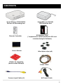
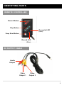
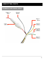
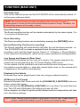
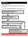
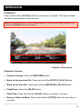
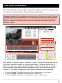
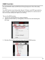
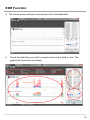
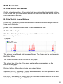
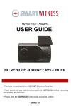
SVC400GPS VEHICLE JOURNEY RECORDER USER GUIDE l Thank you for purchasing this Journey Recorder. l Please ensure that you read and understand this USER GUIDE and use it before connecting and installing this Recorder. l Please store the USER GUIDE in an easily accessible location. VER 2.0 FCC INFORMATION TO THE USER This equipment has been tested and found to comply with the limits for a Class B digital device, pursuant to part 15 of the FCC Rules. These limits are design ed to provide reasonable protection against harmful interference in a residentia l installation. This equipment generates, uses and can radiate radio frequency energy and, if not installed and used in accordance with the instructions, may c ause harmful interference to radio communications. However, there is no guar antee that interference will not occur in a particular installation. If this equipme nt does cause harmful interference to radio or television reception, which can b e determined by turning the equipment off and on, the user is encouraged to tr y to correct the interference by one more of the following measures: - Reorient or relocate the receiving antenna. - Increase the separation between the equipment and receiver. - Connect the equipment into an outlet on a circuit different from that to which t he receiver is connected. - Consult the dealer or an experienced radio/TV technician for help. WARNING Any changes or modifications not expressly approved by the manufactur er could void the user’s authority to operate the equipment. 2 SAFETY ADVICE CAUTION RISK OF ELECTRIC SHOCK DO NOT OPEN CAUTION: TO REDUCE THE RISK OF ELECTRIC SHOCK, DO NOT REMOVE COVER. NO USER-SERVICEABLE PARTS INSIDE. REFER SERVICING TO QUALIFIED SERVICE PERSONNEL. Please make sure you follow the safety advice/instructions given in the user guide. Caution RISK OF EXPLOSION IF BATTERY IS REPLACED BY AN INCORRECT TYPE. DISPOSE OF USED BATTERIES ACCORDING TO THE INSTRUCTIONS. Battery for RTC (Real Time Clock) inside Caution Connect your vehicle’s power cable to the product after starting the vehicle. The instant over voltage generated when starting up the vehicle may damage the product if it is already connected. Caution Install the product where it does not block driver’s visibility and where there is no airbag installed. This could cause an accident or might injure passengers in case of accident Caution Damages due to production malfunction, loss of data, or other damages occurring while using this product shall not be the responsibility of the manufacturer. Although the product is a device used for recording videos, the product may not save all videos in the case of a malfunction. In the case of an accident, the sensor may not recognize the shock when the impact is light and as a result it may not begin recording automatically. WARNING: TO PREVENT FIRE OR ELECTRIC SHOCK HAZARD, DO NOT EXPOSE THIS APPLIANCE TO RAIN OR MOISTURE. 3 Contents GPS Reception ………………………………………………........... 5 Box Contents ………………………………………………………... 6 Identifying Parts …………………………………………………….. 7 Function …………………………………………………………..….. 10 Operation ………………………………………………………..…… 12 Software User Guide ……………………………………………….. Software Installation ……………………………… Connecting the SD Memory Card ………………. SW Analysis Software Setting …………………... Select File For Playback …………..……………... Playback Screen ………..……………………….… Playback …………………………………………..… Google Maps ………………………………............. Thumbnail Function ………………………………. Save JPG File & AVI Files .…………………...…... Printing an Image ……….……………..………….. Generating a Report ……….…………………..…. Backup Even/Log Files …………………………… Setting the Drive Recorder ..…………………….. Log File Playback ……………………………….… GPS Log to KML Converter …………………..…. EDR Function …………………………………….… 17 18 19 20 21 22 23 25 26 27 28 29 30 31 38 39 40 Accessories …………………………………………………….……… 52 Specifications ………………………………………………….…….... 53 Technical Support and Warranty …………………………………… 54 4 GPS RECEPTION 1. Activate the product in an area without large buildings to impr ove GPS reception. The commercial purpose GPS has the average range error of more than 15 meters and the range error could be more than 100 meters due to environmental conditions like buildings, roadside trees etc. 2. The temperature range for optimum operation of the GPS receiver in your car is -10 ~ 50°C. 1. When using the product for the first time or after a long perio d (more than three days), it may take a little longer to recogni ze your current location. It may take between five and thirty minutes to get GPS reception. GPS reception may be impaired under the following circumstances 1) If there is an object at the end of the GPS antenna 2) If your vehicle has metallic elements on the windshields 3) If equipment generating electromagnetic waves that interfere with the GPS signal is installed in the vehicle e.g.: Other GPS devices such as a certain type of wireless activated alarms, MP3 and CD players and camera alarms using GPS. 4) If you are using a receiver connected by cable, electric interference can be avoided by simply changing the location of the receiver (antenna). 5) On heavily overcast or cloudy days, if the vehicle is in a covered location such as under a bridge or raised roadway, in a tunnel, an underground roadway or parking area, inside a building or surrounded by high-rise buildings. 6) If GPS signal reception is poor, it may take longer to locate your current position when the vehicle is moving than when it is stationary. 5 CONTENTS Smart Witness SVC400GPS Receiver & Recording Unit Remote Controller Velcro Sticker Sticker for mounting (double-sided 3M tape) Camera Input Cable (x3) Smart Witness SVC400 GPS Antenna Unit SD Memory Card * (* dependent on model purchased. SD card includes Analysis Software) Wire Splice clips (x5) Power Cable AV Output Cable 6 IDENTIFYING PARTS SVC400GPS JOURNEY RECORDER FRONT Audio/Video Output Camera 3 Input SD Door External MIC input SD Slot Speaker REAR Internal Microphone Remote Control Input GPS Input Camera Input 1, 2 Power Input & Alarm (Car Signal) Input Rear View Camera 4 Input 7 IDENTIFYING PARTS REMOTE CONTROLLER Record Button Play Button Overwrite LED (Red) Snap Shot Button Record LED (Blue) AV OUTPUT CABLE Audio Output Video Output 1 Video Output 2 8 IDENTIFYING PARTS POWER & CAR SIGNAL INPUT Power (+) (Red) Ground (Black) Alarm 1 (Blue) Fuse 250V 3A Alarm3 (Yellow) Car pulse (speed) (White) Alarm 2 (Green) 9 FUNCTION (MAIN UNIT) Automatic start Turn on the vehicle’s power and the SVC400GPS will be automatically started. (U se the power cable provided). NOTE: The unit will not start recording immediately after the power is turned on. It takes around 1 minute for the built-in power backup system to charge. Thereafter, the internal flash memory will be ready to record. Event Recording The Event recording function will be started automatically by the alarm inputs (1 to 3) or by the G-Sensor level. Panic Recording The Panic recording function can be started by pressing the [RECORD] button. Normal Recording (Continuous recording) The Normal recording will automatically start after the unit has been powered on. The SVC400GPS will not make a separate Event file during continuous recording. It will mark the Event area as ‘Alarm1-3’, ‘G-Sensor’ or ‘Record Button’ in the continuous recording file ,which can be easily searched for during playback. Live Screen and Camera 4 (Rear View) SVC400GPS will display the live view on a monitor. The camera channel to be viewed can be changed using the On Screen Display (OSD) menu. To use camera 4 as an automatic rear view camera the user can power it from the vehicle’s reverse lights (i.e. when the reverse lights come on, the camera will b e displayed on the monitor automatically) Playback in the Vehicle Recorded files can be played back in the car (using an optional monitor). SD Memory Card Format Remove the power first. Press and hold the [PLAYBACK] & [RECORD] button an d then connect the power. Press and hold the [PLAYBACK] & [RECORD] for more than 2 seconds after boo ting. Then SD card initialization (formatting) process will start. Once complete, all video & log files will be deleted and the configurations will defa ult to the factory settings. NOTE: Smart Witness Analysis Software is pre-loaded on the SD card. Please ensure y ou have installed the software to your PC before you format the card 10 FUNCTION (MAIN UNIT) Built-in Power Backup If power to the unit is interrupted the SVC400GPS creates the last file using its internal battery. Blue LED (RECORDING) The Blue LED shows the power is on (It will flash during event recording) Red LED (WARNING) The Red LED will turn on when there is video loss or the system has failed. BUZZER A ‘Beep’ sound will occur when event/panic recording starts (this can be turned off if required) and to signal a system error. VIDEO LOSS (WARNING) “Beep” sound will occur continuously when there has been a video loss. Check the camera(s) and its connections . Make sure of the number of camer as that you connect before you turn on the unit (the number of cameras can be set in the settings menu on the Smart Witness Analysis Software .) 11 OPERATION Begin Recording 1. Make sure that the power cable is properly connected and then turn on the cars power. 2. The Blue LED & Red LED will turn on and begin to flash slowly and simultaneously. The Blue LED will then remain on by itself, illustrating that the SVC4000GPS is ready for recording. NOTE: Recording Modes • Normal recording (Continuous Recording) will start automatically (if configured that way with your PC) • Event recording will automatically begin when triggered by the G-Sensor and will begin with one short ‘Beep’ sound. • Panic/Manual recording can be started by pressing the [RECORD] button. Removing the SD memory card Turn off the power to the unit and once the Blue LED light has turned off only then remove the SD Memory Card. Inserting the SD memory card Turn off the power to the unit and once the Blue LED light has turned off only then insert the SD Memory Card. System Error Buzzer A ‘Beep Beep’ sound will occur and the Blue & Red LED lights will flash simultaneously when there is a system error or if the SD card has not been inserted. Please check the SD Memory Card is inserted correctly when this occurs. 12 OPERATION INFORMATION OSD Press the [PLAY] button and the Information OSD will show up on the monit or as below: CAM2 √ CAM3 CAM4 Ac+vated CAM1 √ √ √ Record Mode Normal Normal Event Event System : NTSC Resolu+on : 720X480 FPS : 5 Audio : ON Quality : Super Overwrite : ON G-‐Sensor Level : X:3, Y:3, Z:3 G-‐Sensor Calibra+on : √ Firmware Version : 2.0.1 Current Time : 14:50:07 07 JUL 2011 § To change the live display channel, press [RECORD] button. § The INFORMATION OSD will be turned off automatically after 30 seconds. § To turn off the live view, press [PLAY] button or [STOP] button. LIVE VIEW Turn on the SVC400GPS and press the [PLAY] button to turn on the Informati on OSD To change the live display channel press the [RECORD] button to select the c amera and then press the [PLAY] or [STOP] button to escape. If Camera 4 (Rear View camera) is on, the Live View display camera will be automatically switched to display Camera 4. Cam 1 Cam 2 Cam 3 Cam 4 4 Camera Split Screen 13 OPERATION G-SENSOR CALIBRATION G-Sensor Calibration is needed after installing the SVC400GPS. This allows it to determine how it has been installed so that it accurately records the journey direction. § Press and hold the [PLAY] & [STOP] buttons together and then turn on the power. The G-Sensor Calibration screen will be displayed as follows : Press and hold RECORD and STOP buYon simultaneously more than 2 sec for calibra+on Press any single buYon to escape Park vehicle on a flat surface with at least 50 meters of space directly ahead and press RECORD buYon once Move directly forward and accelerate vehicle +ll beep soun d occur G-‐Sensor Calibra+on is finished successfully Press any buYon or wait 30 seconds to reboot Retry G-‐Sensor Calibra+on is failed Park vehicle on a flat surface with At least 5 meters of space directly ahead And press RECORD buYon once again Note: This G-Sensor Calibration is only needed the first time the SVC400GPS has been installed or has been relocated. 14 OPERATION Panic Record (by the panic button) Begin recording automatically by pressing the RECORD button. Recording will start with one short ‘Beep’ sound and the Blue LED will be flash during the recording. The SVC400GPS will not make a separate event file during the continuous recording. It will mark the Event area as ‘Record button’ in the continuous recording file which can be easily searched for during playback. Snap Shot (by the stop button) By pressing the [SNAPSHOT] button the SVC400GPS will take a snapshot of 1 image with 5 seconds of audio with one short ‘Beep’ sound. 15 OPERATION PLAYBACK Press and hold the [ PLAY] button for more than 2 seconds. The last recorded file will be played back on the screen. Note: Recording cannot be done during playback. If the Event Recording function is o n then the [PLAY] button will not work. Playback Control panel Playback Controls: § Channel change: Press the [RECORD] button § Move to the previous file: Press and hold the [STOP] & [PLAY] button § Move to the next file: Press and hold the [RECORD] & [PLAY] button § Play/Pause: Press the [PLAY] button § Slow Play: Press and hold the [PLAY] button more than 1 second § Return to Record Mode: Press and hold the [STOP] button for more than 2 seconds 16 SOFTWARE USER GUIDE SVC400 – Vehicle Journey Recorder Analysis Software PC SYSTEM REQUIREMENT Recommended PC specifications for SmartWitness software OS Windows 2000, Windows XP Windows Vista, Windows 7 CPU Pentium4 2.6GHz or higher RAM 512MB or higher Interface SD Memory Card Reader HDD Free space Install 20MB or higher Backup 2GB or higher Display 1,024 x 768 pixel/High Color(16bit) or higher If the PC does not meet the minimum system requirement, the SmartWitness software may not function properly. 17 SOFTWARE INSTALLATION Smart Witness Analysis Software is on the provided SD card. § 1. Connect the SD card into your PC (if your computer does not have and S D card slot use a USB SD card reader) and open “My Computer” § 2. Right-click the “DRIVEREC1” drive and select OPEN § 3. Double click ‘pcsw’ folder and then the SETUP.EXE § 4. Select the language and then follow the dialog box § The “SmartWitness ” icon will be displayed on your desktop. NOTE: To Un-install the SmartWitness Analysis Software § Open the ‘Control Panel’. § Select ‘Remove Program’ and remove the Smart Witness Analysis Software 18 Connect SD Memory Card § Connect SD memory card in to the SD card reader § Run ‘Smart Witness’ § Select FILE and then click ‘Select Data Folder’ or click the OPEN button [OPEN] button § Select SD memory card folder at the folder select window. or 19 SMART WITNESS ANALYSIS SOFTWARE To setup the Smart Witness Analysis Software select FILE and then click ‘PC Viewer Setting(S)” Note: This setting is for the Smart Witness Analysis Software (for recorder r efer to page 27) The ‘Date Formats’ and ‘Speed Unit’ will be set automatically according to the P C Windows setting. However it can be changed within this setting menu. To see the better quality playback picture on your PC, check the “Deblocking” b ox. 20 SELECT FILE FOR PLAYBACK § Check the file from the list using a mouse or click the ‘All’ button and then click the ‘Load’ button. Check the event(s) individually ‘G-Senor’ means recording was Activated by an Impact; ‘Switch’ means recording was activated by a button OR Check ‘All’ files Button Load Button § All recordings and snapshot files will appear the file area under the tabs: The Event file list (recorded by a triggered G-Sensor or Alarm1-3) The Panic file list (recorded by pressing the [RECORD] button The Continuous recording file list. The Snapshot file list (saved by pressing the [SNAPSHOT] button The Log file list. 21 PLAYBACK SCREEN Event data in the Playlist [NOR]: Normal Recording [G-Sensor]: Event Recording Display frame/Total number of frames Playback position indicator The Yellow Mark indicates there is An Event triggered by the G-Sensor , Alarm1~3 or the RECORD button. Check box for continuous playback This button is enabled when playing back recorded file(s). Camera Names The ‘icon names’ can be changed in the Settings Menu. e.g.: or G-Sensor Data UD: Up/Down direction FR: Front/Rear direction LR: Left/Right direction GPS location data (the north latitude, the east longitude) 22 PLAYBACK 6. Click (PLAY button) for playback. Volume CH1 CH3 CH2 Playback speed CH4 Date & Time Drag & Move the white line to move the playback position. Playback buttons x2, 4, 8, 16 Fast Reverse x0.5, 1 Reverse Previous Image x0.5, 1 Play Pause x2, 4, 8, 16 Fast Forward Next Image Single View (CH1, CH2, CH3) Quad View 4x4 Multi View (Thumb-nail function) Zoom In G-Sensor graph Reset Zoom Zoom Out G-Sensor graph 23 PLAYBACK PC KEYBOARD HOT BUTTONS FUNCTION PC KEYBOARD HOT BUTTONS 1024x768 mode Enter (Return to the previous mode: Enter) Full screen mode Alt + Enter (Return to the previous mode: Enter) Playback speed control Ctrl + F 0.5 => 1 Reverse playback speed control Ctrl + B 0.5 => 1 Pause / Play Space Previous Image → direction button. Next Image ← direction button 24 GOOGLE MAPS (for ‘Event’ Recording Files) The route taken will be displayed on the Google map at lower right corner of the software. Note: • To see the route and position on the Google map, the GPS data should be recorded with video. • To see the map, the PC should be connected to the Internet. • The playback position will be shown on the map with an arrow. • The blue markings show the route taken. Zoom Out • Double click the blue mark to change the video playback position to that point. • The camera icon indicates that there is a recorded file • The total camera icons shown will be less than 100, even if there are more than 100 events. • When the unit is set to Normal recording mode, there will be no route & camera icon on the map. 25 THUMBNAIL FUNCTION § Click button for 4x4 multi view (Thumbnail function) Click the thumb-nail image to change the playback position Click the CLOSE button to finish the event playback. The ‘PlayList’ window will changed to its initial status. Note: Click the right mouse button to go back to single image playbac k mode 26 SAVING JPG FILE & AVI FILES Pause the playback and click ‘Save Image’ icon to make a JPG file: ‘Save Image’ icon Pause the playback and Click ‘Save AVI’ icon to make a AVI file: ‘Save AVI’ icon 27 PRINTING AN IMAGE Pause the playback and click ‘Print Image’ icon: ‘Print image’ icon Input the file name (Print Title) & any notes (Print Comment) using Keyboard. T he Print comment window allows up to 7 lines in total: 28 GENERATING A REPORT § Click the ‘PRINT’ button in the print preview windows for printing. The file na me (Print Title), any notes (Print Comment), G-Sensor graph & map will be pr inted on the first page. The second page will print the images selected. § Click ‘2x2’ and then click ‘Print’ to print 4 images in one page: § To print CH1-4 together select 1 frame only 29 BACKING UP EVENT/LOG FILES § Click the ‘Backup’ icon to backup the files to the PC ‘Backup’ icon § Select and Load ‘Event’, ‘Normal’, ‘Panic’, ‘Log’ & ‘Memo’ data first, befo re clicking the ‘Backup’ icon. The selected files will appear in the lists in t he Backup window. OR § Check ‘Backup All’ and press the ‘START’ button to backup ‘All Files’. 30 SETTING THE DRIVE RECORDER § Click the ‘Setting Drive Recorder’ icon for setup ‘Setting Drive Recorder’ icon IMPORTANT Backup SD Card data first, before clicking the ‘Initialize SD card’ button OR before changing the Record Mode from Normal to Event or vice vers a. All normal recording data or all event recording data in SD card will be automatically deleted to make a free space on the SD Card. Note: Once done the old data cannot be recovered. Record Mode Change: All normal recording data or all event recording data in SD card will be automatically deleted to make a free space on the SD Card. Initialize SD card: All data will be deleted and set the configuration of Drive Recorder will default to the factory settings. 31 SETTING THE DRIVE RECORDER CAMERA SETTINGS Select level of Mot ion Sensitivity Select the relevan t check boxes for the cameras you want to record (in cluding Audio) Select the relevant check boxes for the cam eras you want to record for motion detection. To use motion detection as an Event recordi ng select the recording mode as Event Mod e and then the select the corresponding chec k box for motion Normal Mode Continuous recording will automatically start after booting the SVC400GPS. Event Mode Recording by G-Sensor, Alarm1~3 or [RECORD] button. Motion Sensitivity Select Motion Detection Sensitivity from 1 to 5. (5 is the setting for the highest sensitivity and 1 is the lowest sensitivity) 32 RECORD SETTINGS Resolution PAL: 720x576, 720x288 NTSC: 720x480, 720x240 FPS (Frames Per Second) 1 Camera supports 1~25 fps@ 720x576, 1~25 fps @ 720x288 1 Camera supports 1~30 fps@ 720x480, 1~30 fps @ 720x240 2 Cameras supports 1~12 fps @ 720x576, 1~25 fps @ 720x288 2 Cameras supports 1~15 fps @ 720x480, 1~30 fps @ 720x240 3 Cameras supports 1 ~ 8 fps @ 720x576, 1~12 fps @ 720x288 3 Cameras supports 1~10 fps @ 720x480, 1~15 fps @ 720x240 4 Cameras supports 1 ~ 4 fps @ 720x576, 1~12 fps @ 720x288 4 Cameras supports 1 ~ 5 fps @ 720x480, 1~15 fps @ 720x240 Overwrite Overwrite (The image data is overwrites the oldest files when the SD memory is full.) One time (The recording stops automatically when the SD mem ory is full.) Quality High (Large file size, but good picture quality) Low (Small file size, but low picture quality) Pre Event/ Post E vent Pre-record/Post-record time can be set here. Pre-record time is 5~30sec, if total frame rate is below 8fps @ 7 20x576 or 10fps @ 720x480. Pre-record time is 5~25sec, if total frame rate is 12fps @ 720x57 6 or 15fps @ 720x480. Pre-record time is 5~15sec, if total frame rate is 25fps @ 720x57 6 or 30fps @ 720x480. Post-record time is 5~300sec Max. Number of Panic Button Rec ord This can be set between 5~500. If you set different record modes per camera (Normal Mode and Event Mode), the Max Number of Panic button Record will be 5~10 33 SETTING THE DRIVE RECORDER ALARM SETTINGS To record the car signal with video, set the Alarm configuration as below: To use the Alarm as an Event trigger, (i.e.: so Event recording will start when a door is opened or a Meter is on) set the Alarm configuration as below: G-SENSOR SETTINGS If G-Sensor sensitivity value is too high (like 1), it may be too sensitive, so it will detect even a light impact or light turn. If the G-Sensor sensitivity value is too dull, it may not detect a notable incident. So, sensitivity should be set in consideration of a vehicle’s suspension, condition and also the road condition. If you do not want to record an Event by G-Sensor, un-check Event Record box . 34 SETTING THE DRIVE RECORDER SYSTEM SETTINGS Vehicle ID Type in your Vehicle ID Password Enter 4 numbers from 1000 to 9999 as a password “Search on system” function (i.e. playback on a car) will not work after the password has been set Buzzer Set the ‘Beep’ sound ON/OFF when Event recording starts Video Type This should be set to PAL Search on system To use the playback function on the recorder. DATE/TIME SETTINGS Time Zone: GMT This setting will allow you to set the Time Zone and synchronize the time using GPS Time. DST Check this box to activate Daylight Saving Time Manual Time Setting Check this box to set the time manually. 35 SETTING THE DRIVE RECORDER SD CARD SETTINGS IMPORTANT: Backup SD Memory Card first, before deleting any data. Init SD Card Initialize SD Card: All data will be deleted and the Drive Recorder will default to the factory settings. Delete Recorded Data All data will be deleted off the SD Memory Card WARNING: Once Setting have been changed, all recorded data will be removed automatically. Select YES or NO to the Backing Up Data option to continue. NEW SD MEMORY CARD INITIALISATION NEW SD Memory card initializing should be done using Tool menu. 1. Insert new SD memory card into the PC. 2. Run “Smart Witness Analysis Software” 3. Select TOOL from the menu and then click ‘SD Initialize’ We recommend you initialize the SD Memory Card at least once per month to prevent the SVC400GPS from getting any software errors. 36 SETTING THE DRIVE RECORDER ABOUT PRODUCT INFORMATION Click the ‘About’ icon to check the product information. ‘About’ icon 37 LOG FILE PLAYBACK Select the LOG tab window and then check the log file from the list using mouse or click the ‘Check All’ button. Then click the ‘Load’ button. Journey Log data will be recorded during driving even if there are no events. The total log data size can not exceed 48MB. The unit overwrites the oldest data when 48MB is reached. Using this log data, we can use the data sorting function to help find specific data (for example, to find all the times when the vehicle was travelling at more than 80mph (or 80km) Search button Input sorting data G-Sensor graph GPS speed, G sensor X value, G sensor Y value, G sensor Z value data can all be used to narrow a search for journey information. The small check box at right side of each value should be ticked before the data for search is inputted. If any recorded video data matches the search query, a list will show up with ‘Switch’ or ‘G-Sensor’ indicators to show how the recording was triggered. § G sensor X value: Front/Back movement (like a harsh brake or quick start) § G sensor Y value: Left/Right movement (like a harsh Turn) § G sensor Z value: Up/Down movement (like a bump or depression) 38 GPS LOG TO KML CONVERTER (for Google Earth) To see the whole route on Google Earth, select the log file and click the Google Earth button. 1. Install the Google Earth on your PC. (http://earth.google.com/) 2. Check the log file 3. Click Google Earth in the Tool menu We recommend to use Google Earth Version 5.0 or above. Tip: Click ‘Car Track’ and then Click ‘Play Tour’ button to play the recorded Journey in Google Earth. 39 EDR Function The SVC400GPS offers an EDR (Eco-Driving Analyser for Drive Recorder) function. The EDR function uses driving data: Speed, G-Sensor and GPS generated by drive recorder to analyse and quantify driving information for a set amount of time to increase safety and improve eco-driving. The use the EDR function: 1. Launch the SVC400GPS PC Viewer Software. 2. Select the data folder by clicking [file] on the tool bar and selecting the SD Card. 3. Click the [Tool] button and scroll down and click [EDR] function. 40 EDR Function 4. The below screen will pop up showing a list of the data files. 5. Check the data files you wish to analyse and click [Load] to view. The graphs will be shown as follows: 41 EDR Function A. Data File List and Calendar On the calendar section, all the dates that have data will be highlighted in blue. Click on the date you wish to view and all the data from that day will be listed on the Data File List section. B. Data File List Control Buttons [Select All], [Unselect]: Utilise these buttons to select the data files you wish to view more efficiently. [Load]: This button should be used to load the selected data. C. Drive Data Graph The Drive Data Graph displays, Speed and G-Sensor information for the file selected by the user. 1) Speed The axis on the left hand side indicates Speed. The Scale can be configured in the Setup Menu. The Speed is shown as the red line of the graph. The colour key at the top of the page explains the progress bars on the bottom of the graph. Driving / Idling – Blue when driving, grey when Idling Speeding (ECO) / Speeding – Green when exceeding the eco-speed limit, and red when exceeding the speed limit. Eco-RPM / Excess RPM – Blue when the vehicle’s exceeds the Eco-RPM limit and red when exceeding the RPM limit. 42 EDR Function 2) G-Sensor Graph The axis on the left hand side indicates the acceleration force in gs (1g = 9.81m/s2) The red graph line displays the forces from acceleration / deceleration(X axis) The green graph line displays forces left and right (Y axis) The blue graph line displays the forces from top to bottom (Z axis) The colour key at the top of the graph explains the colours on the progress bar on the bottom. Normal / Sdn Start. Accel. Brake: Grey when driving normally, red when there is a sudden acceleration, deceleration or turn. D. Drive Information Summarizes the drive using the selected data. 43 EDR Function E. Tools There are 3 tools offered in this function; (From left to right) Zoom, Map and Print Daily Report. 1) Zoom When you click the zoom button on the tool bar of the graph, the screen will pop up as shown above. The user can zoom in on a certain part of the drive data graph by clicking the point they wish to see. The bottom scale bar can also be changed in the setup to accommodate for this (i.e. Change from 1 min to 10 min). The arrow keys can also be used to advance or retreat from the pre-selected point in time. 44 EDR Function The user can also print out the detailed Zoomed Graph Report by clicking the [Print] button in the bottom right corner (Below). 45 EDR Function 2) Driving Map Click on the Driving Map button on the tool bar to view the driving map (above) This will bring up a map showing the whole route of the selected data. When clicking on a certain point on the Drive data graph, an orange arrow will indicate the location at that certain point on the map. 46 EDR Function 3) Daily Report Print When the Daily Report Button is clicked, a report (below) will print, showing various graphs and analysed information. 47 EDR Function F. Set up To continue the function and display, click the [setup] button on the bottom left corner of the main display screen. 1) Analysis Criteria Settings Acceleration/Brake Scroll down to select the limit the G-Sensor value for acceleration/deceleration. Any force exceeding this limit will be classified as sudden start or stop and the unit will start recording. Speed Limit Set the speed limit and duration of speeding that you wish to use. For example, if you drive over 60mph for more than 10 seconds, it will count as speeding. Eco Speed Limit Set the eco-speed limit and duration of speeding. (This may be different to the normal speed limit) RPM Limit Set the RPM limit and duration of exceeding the limit. (If the RPM limit is exceeded for more than 10 seconds, the driver score will decrease). 48 EDR Function 2) Grading Criteria Settings This sets the grading criteria for each grading category. For example, If the settings are as above, and you experience a sudden acceleration for 0.7 timer per hour on average, you will get a grade B in that category. 49 EDR Function Point/Weight Settings This sets out the numerical score and weights for each grade. For example, if the settings are as above, your B grade for sudden acceleration will be scored as 80 and since the weight is 14%, your eco score will be 11.2 points. Calculation of Safety Score, Eco Score and Total Score The safety score is calculated by adding up all the weighted points from 7 Categories: Sudden Start count, acceleration count, sudden stop count, speeding count, speeding duration ratio, peak speed relative to the speed limit and average speed Relative to the speed limit. 50 EDR Function Eco-score is calculated by adding up all the weighted points from 5 categories: Sudden start count, acceleration count, sudden stop count, eco-speeding count and eco-speeding duration ratio. The total score is the average of the safety score and eco-score. 3) Graph Display Setting Max Speed: This sets the maximum value of graphs’ speed scale. Max G-Sensor: This sets the maximum value of the graphs’ G-Sensor scale. Max RPM: This sets the maximum value of the graphs’ RPM scale. (Can only be used when RPM data can be inputted.) Zoom Window Display Time: This sets the time period, in minutes, displayed on the zoom graph. 51 ACCESSORIES CAMERAS Micro Waterproof and Tamper Resistant Camera See diagram below for connection to the SVC400GPS unit: SVC400GPS Rear Power/Video Cable To Camera HIGH RESOLUTION VANDAL RESISTANT COLOUR CAMERA WITH IR NIGHT VISION. INCLUDES BRACKET. See diagram below for connection to the SVC400GPS unit: SVC400GPS Rear Video Camera Input Cable SVC400GPS Front Audio To Camera -/+ Power Connections Phono to Headphone Connector Connect For Audio Recording (optional) 52 ACCESSORIES MONITORS 7” LCD MONITOR CAN BE USED WITH THE SVC400GPS TO VIEW IMAGES FROM THE CAMERAS, PLAYBACK RECORDINGS AND ALSO AS A REAR VIEW MONITOR WHEN REVERSING. See diagram below for connection to the SVC400GPS unit: SVC400GPS Front Video Input Video In To Monitor (not used) (not used) Audio Input AV Output Cable (supplied with SVC400GPS unit) ADDITIONAL ACCESSORIES INTERNAL MICROPHONE See diagram below for connection to the SVC400GPS unit: SVC400GPS Front Audio Input To Microphone SECURITY BRACKET USED TO SECURE AND PROTECT THE SVC400GPS UNIT WHEN IN A VEHICLE. 53 SPECIFICATION SVC400GPS Video CH1 (Front), CH2 (Interior), CH3 (Interior), CH4 (Rearview) Audio I Channel (Internal / External Microphone) Continuous/Event Recording Speed NTSC: 720x480 (30fps) 720x240 (60fps) PAL: 720x576 (25fps) 720x288 (50fps Snapshot Record Still Image with 5 seconds Audio Backup SD Memory Card Memory 4GB SD memory card (supports SDHC cards of up to 32GB) GPS External GPS Module G-Sensor Internal 3-axis G-Sensor Car Signal Car Pulse for Speed (and Brake, Left Turn, Right Turn when connected to Alarm Inputs) Alarm Input 3 Compression MPEG4 (Continues recording) MJPEG (Event recording) Remote controller Panic/Record button, Playback button, Snapshot button Buzzer Recording start, error LED 2 (Red/Blue) Super Capacitor Battery Enables recording of last file and shut down PC Software Supplied AV Out 1 Video Out 1 Audio Out Power Input 12V to 24V DC (cable supplied for hardwiring to vehicle) Power Consumption 8.3W (12V x 691mA) When recording 4 cameras Weatherproof No Mounting Surface mount (optional Security Bracket available) Dimensions (WHD) 99 x 21 x 70mm 54 TECHNICAL SUPPORT & WARRANTY TECHNICAL SUPPORT For Technical Support, please contact your local distributor. LIMITED WARRANTY This product is supplied with 2 year warranty. The Warranty excludes products That have been misused, (including accidental damage) and damage caused by normal wear and tear. In the unlikely event that you encounter a problem with this product, it should be returned to the place of purchase. 55 Manufactured exclusively for: www.smartwitness.com Smart Witness is a Division of Xvision