1
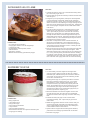
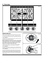
USER GUIDE &
INSTALLATION INSTRUCTIONS
900S Dual Fuel
SLOW BAKED LEG OF LAMB
METHOD
1. Preheat the oven to 220 ¡C (for a conventional oven), 200 ¡C
(for a fan oven) or gas mark 7.
2. Pull the small sprigs off the rosemary branches and set aside
with the garlic.
2. Using the tip of a paring knife, make up to 20 well-spaced
cuts into the flesh of the lamb, about 2.5 cm inch deep.
Divide the rosemary sprigs, garlic and anchovies and push
down into the cuts. Place the leg on a large roasting tin and
pour over the oil, massaging it all over the joint. Season well
with salt and pepper and pour the wine and 250 ml water
into the tin.
3. Put into the oven and sear for 15 minutes, then turn the
temperature right down to 130 ¡C (conventional oven),
110 ¡C (fan oven) or gas mark 1 and roast for 4Ð5 hours,
basting every 30 minutes or so. Basting frequently helps
to keep the meat moist and encourages the build up of a
good glaze on the outside. Add more liquid (wine or water)
if the tin looks dry Ð there should always be liquid in the tin
throughout this cooking process.
INGREDIENTS
¥ 2Ð3 large sprigs of rosemary
¥ 4 large garlic cloves cut in half lengthways
¥ 1.8 kg leg of lamb
¥ 8 good quality anchovy fillets, halved
¥ 100 ml olive oil
¥ 250 ml dry red wine
¥ Maldon salt and freshly ground black pepper
4. The meat is ready when it starts to fall off the bone, at
which point it should have a core temperature of 90 ¡C.
Remove from the oven, transfer to a warmed carving dish,
cover loosely with foil and leave to rest in a warm place for
30Ð45 minutes before carving.
5. Pour the juices from the tin into a tall hi-ball glass and allow
to settle. Spoon the fat from the top of the glass. There
should be enough sticky, reduced juices for an intense gravy
hit Ð if not, pour the juices you have back into the roasting
tin and put it over the heat, pour in a splash of water or wine
and deglaze the tin scraping up all the sticky bits from the
base. Boil fast until syrupy, taste and correct the seasoning.
RASPBERRY SOUFFLÉ
METHOD
1. For the soufflŽ, press the raspberries through a fine
sieve to produce 180 g of purŽe. Put this into a heavybottomed pan, add the lemon juice and reduce down to
a thick jam, stirring from time to time and being careful
not to let it catch and burn.
2. Put 45 g of the sugar in a separate pan. Melt it and then
boil until it becomes a thick syrup (121 ¡C on a sugar
thermometer). To test without a thermometer, dip a
teaspoon into the syrup and then dip quickly into cold
water. You should be able to roll the cooling syrup into
a ball between your fingers. Be careful as the syrup is
extremely hot. When it has reached the right point, stir
the hot syrup into the raspberry jam.
3. Mix the framboise and cornflour together and stir into
the jam over the heat. Turn the jam into a small bowl,
sprinkle the surface with icing sugar and cover with cling
film.
INGREDIENTS
¥ 400 g raspberries
¥ 1 tbsp lemon juice
¥ 100 g caster sugar
¥ 2 tsp cr�me de framboise
¥ 1 tsp cornflour
¥ 180 g egg whites (about 6)
¥ Pinch of cream of tartar or a squeeze of lemon juice
¥ Icing sugar for dusting
4. Preheat the oven (not grill) to 180 ¡C shelf level 2
(conventional oven), 160 ¡C (fan oven) or gas mark 4
centre shelf.
5. Whisk the egg whites with the cream of tartar until you
can form soft peaks, then fold in the remaining caster
sugar. Lightly fold the whites into the jam, leaving thin
traces of white visible in the mixture.
6. Spoon into four large buttered and sugared ramekins,
place these on a baking tray and bake for 10 minutes.
7. Dust with icing sugar.
Contents
1.
Before You Start...
1
6.Troubleshooting
16
Installation and Maintenance
1
Peculiar Smells
1
7.Installation
18
If You Smell Gas
1
Ventilation1
Personal Safety
1
Oven Care
2
Provision of Ventilation
18
Location of Cooker
19
3
Positioning the Cooker
20
Moving the Cooker
20
Levelling21
Hotplate Burners
3
Fitting the Stability Bracket or Chain
22
The Multi-function Oven
6
Gas Connection
22
Accessories9
Pressure Testing
22
Electrical Connection
23
Final Checks
23
Final Fitting 24
Customer Care
24
Oven Light
9
Storage10
3.
18
Conversion19
Cleaning2
2.Overview
Dear Installer
Cooking Tips
11
Cooking with a Multi-function Oven
11
General Oven Tips
11
8. Circuit diagram
25
4.
Cooking Table
12
9. Technical Data
26
6.
Cleaning Your Cooker
13
10. Warranty/After Sales Service
27
Daily Care
13
If you have a problem
Cleaning for Spills 13
Notes27
Cooktop Burners
13
Out of Warranty
27
Stainless Steel Main Top
13
Spare Parts
27
Griddle (optional extra)
14
Control Panel and Oven Doors
14
Cleaning Table
15
Falcon 900S Dual Fuel
i
27
U109968-06A
ii
1. Before You Start...
Ventilation
Thank you for buying this cooker. It should give you many
years of trouble-free cooking if installed and operated
correctly. It is important that you read this section before
you start, particularly if you have not used a dual fuel cooker
before.
Caution: The use of a gas cooking appliance results
nn
in the production of heat and moisture in the room
in which it is installed. Therefore, ensure that the
kitchen is well ventilated: keep natural ventilation
holes open or install a powered cooker hood that
vents outside. If you have several burners on, or use
the cooker for a long time, open a window or turn on
an extractor fan.
This appliance is designed for domestic cooking
nn
only. Using it for any other purpose could invalidate
any warranty or liability claim. In particular, the
oven should NOT be used for heating the kitchen –
besides invalidating claims this wastes fuel and may
overheat the control knobs.
Personal Safety
Do not modify this appliance.
nn
This appliance can be used by children aged from
nn
8 years and above and persons with reduced
Installation and Maintenance
This cooker must be installed in accordance with the relevant
instructions in this booklet, with the relevant national and
local regulations, and with the local gas and electricity supply
companies’ requirements.
physical, sensory or mental capabilities or lack of
experience and knowledge if they have been given
supervision or instruction concerning use of the
appliance in a safe way and understand the hazards
involved. Children shall not play with the appliance.
Cleaning and user maintenance shall not be made by
children without supervision.
Make sure that the gas supply is turned on and that the
cooker is wired in and switched on (the cooker needs
electricity).
The cooker should be serviced only by a qualified service
engineer, and only approved spare parts should be used.
WARNING!
nn
The appliance and its accessible parts become hot
Always allow the cooker to cool and then switch it off at the
mains before cleaning or carrying out any maintenance work,
unless specified otherwise in this guide.
during use and will retain heat even after you have
stopped cooking. Care should be taken to avoid
touching heating elements. Children less than 8
years of age shall be kept away unless continuously
supervised.
Peculiar Smells
When you first use your cooker it may give off an odour. This
should stop after use.
CAUTION: A long term cooking process has to be
nn
supervised from time to time. A short term cooking
Before using for the first time, make sure that all packing
materials have been removed and then, to dispel
manufacturing odours, turn the ovens to 200 °C and run for at
least an hour.
process has to be supervised continuously.
Danger of fire: DO NOT store items on the cooking
nn
surfaces.
To avoid overheating, DO NOT install the cooker
nn
behind a decorative door.
Make sure the room is well ventilated to the outside air
(see ‘Ventilation’ below). People with respiratory or allergy
problems should vacate the area for this brief period.
Accessible parts will become hot during use and will
nn
retain heat even after you have stopped cooking.
If You Smell Gas
•
•
•
•
•
•
•
Keep babies and children away from the cooker and
never wear loose-fitting or hanging clothes when
using the appliance.
Do not turn electric switches on or off
Do not smoke
Do not use naked flames
Do turn off the gas at the meter or cylinder
Do open doors and windows to get rid of the gas
Do keep people away from the area affected
Call your gas supplier
DO NOT use a steam cleaner on your cooker.
nn
1
Always be certain that the controls are in the OFF position
when the oven is not in use, and before attempting to clean
the cooker.
Take care that no water seeps into the appliance.
Only certain types of glass, glass-ceramic, earthenware or
other glazed containers are suitable for hotplate cooking;
others may break because of the sudden change in
temperature.
When the oven is on, DO NOT leave the oven door
nn
open for longer than necessary – otherwise, the
control knobs may become very hot.
This appliance is heavy so take care when moving it.
nn
Note that this appliance has a cooling fan. When an
oven or the grill is in operation the fan will run to
cool the fascia and control knobs.
nn
Oven Care
Always keep combustible materials, e.g. curtains, and
flammable liquids a safe distance away from your cooker.
Cooking high moisture content
foods can create a ‘steam burst’
when the oven door is opened.
When opening the oven stand
well back and allow any steam to
disperse.
DO NOT spray aerosols in the vicinity of the cooker
nn
while it is on.
Use dry oven gloves when applicable – using damp gloves
might result in steam burns when you touch a hot surface.
Do not use a towel or other bulky cloth in place of a glove – it
might catch fire if brought into contact with a hot surface.
NEVER operate the cooker with wet hands.
nn
NEVER heat unopened food containers. Pressure
nn
build up may make the containers burst and cause
ArtNo.062-0003 - 90SC - Prof+ steam burst
DO NOT use aluminium foil to cover shelves, linings
nn
or the oven roof.
injury.
CAUTION!
nn
The inside door face is constructed with toughened
DO NOT use unstable saucepans. Always make sure
nn
that you position the handles away from the edge of
safety glass.
Take care NOT to scratch the surface when placing
cookware on the glass panel.
the hotplate.
Never leave the hotplate unattended at high heat settings.
Pans boiling over can cause smoking, and greasy spills may
catch on fire. Use a deep fat thermometer whenever possible
to prevent fat overheating beyond the smoking point.
DO NOT drop or rest objects on the door glass.
nn
Although the glass is very strong, a sharp blow or a
falling object might cause the glass surface to crack
or break.
WARNING!
nn
Unattended cooking on a hob with fat or oil can be
DO NOT use harsh abrasive cleaners or sharp metal
nn
scrapers to clean the oven door glass since they can
dangerous and may result in fire.
scratch the surface, which may result in shattering of
the glass.
NEVER leave a chip pan unattended. Always heat fat
slowly, and watch as it heats. Deep fry pans should
be only one third full of fat. Filling the pan too full
of fat can cause spill over when food is added. If you
use a combination of oils or fats in frying, stir them
together before heating, or as the fats melt.
nn
Make sure the shelves are pushed firmly to the back
nn
of the oven.
DO NOT close the door against the oven shelves.
nn
Accidental damage may cause the door glass panel
to fracture.
Foods for frying should be as dry as possible. Frost on frozen
foods or moisture on fresh foods can cause hot fat to bubble
up and over the sides of the pan. Carefully watch for spills or
overheating of foods when frying at high or medium high
temperatures. Never try to move a pan of hot fat, especially a
deep fat fryer. Wait until the fat is cool.
Keep oven vent ducts unobstructed.
nn
Cleaning
In the interests of hygiene and safety, the cooker should be
kept clean at all times as a build up in fats and other food
stuff could result in a fire.
Do not use the top of the flue (the slot along the back of
the cooker) for warming plates, dishes, drying tea towels or
softening butter.
Clean only the parts listed in this guide.
Clean with caution. If a wet sponge or cloth is used to wipe
spills on a hot surface, be careful to avoid steam burns. Some
cleaners can produce noxious fumes if applied to a hot
surface.
DO NOT use water on grease fires and never pick
nn
up a flaming pan. Turn the controls off and then
smother a flaming pan on a surface unit by covering
the pan completely with a well fitting lid or baking
tray. If available, use a multi-purpose dry chemical
or foam-type fire extinguisher.
2
2. Overview
Fig.2-1
ArtNo.250-0004 - Falcon 900S hotplate layout
Hotplate Burners
Fig.2-2
Before using the hotplate make sure all burners are in place
and all the pan supports on the cooker are properly placed.
The drawing by each knob indicates which burner that knob
controls (Fig.2-1).
ArtNo.250-0001 - 90 DF - Falcon control to HIGH
Each burner has a Flame Supervision Device (FSD) that stops
the flow of gas if the flame goes out.
When a hotplate burner knob is pressed in, sparks will be
made at every burner – this is normal. Do not attempt to
disassemble or clean around any burner while another
burner is on. An electric shock could result.
To light a burner, push in and turn the associated control
knob to the high position indicated by the ‘large flame’
symbol, (Fig.2-2).
Fig.2-3
The igniter should spark and light the gas. Keep holding the
knob pressed in to let the gas through to the burner for a few
seconds (Fig.2-3).
If, when you let go of the control knob, the burner goes out,
then the FSD has not been bypassed. Turn the control knob
to the OFF position and wait for one minute before you try
again, this time making sure to hold in the control knob for
slightly longer.
ArtNo.250-0003 - Falcon control
knob push-in
3
Adjust the flame height to suit by turning the knob. On this
cooker the low position is beyond high, not between high
and off. The ‘small flame’ marks the low setting (Fig.2-4).
Fig.2-4
Make sure flames are under the pans. For safety reasons,
adjust the flames so that they do not extend beyond the
edge of the cooking utensil. Using a lid will help the contents
boil more quickly (Fig.2-5).
ArtNo.250-0002 - 90 DF - Falcon control knob
Pans and kettles with concave bases or down-turned base
rims should not be used (Fig.2-6).
Simmering aids, such as asbestos or mesh mats, are NOT
recommended. They will reduce burner performance and
could damage the pan supports (Fig.2-7).
Fig.2-5
Avoid using unstable or misshapen pans that may tilt easily
and pans with a very small base diameter e.g. milk pans,
single egg poachers (Fig.2-8).
The minimum pan diameter recommended is 120 mm for the
outer burners and 160 mm for the centre burner.
DO NOT use cooking vessels that may overlap the edges of
the hotplate.
ArtNo.311-0001 Right pans gas
Fig.2-6
ArtNo.311-0002 Pan with rim
Fig.2-7
Art No. 311-0003 Simmer aids
Fig.2-8
ArtNo.311-0004 Tipping wok
4
The Multi-function Oven
A
As well as the oven fan and fan element, they are fitted with
two extra heating elements, one visible in the top of the oven
and the second under the oven base (Fig.2-9). Take care to
avoid touching the top element and element deflector when
placing or removing items from the ovens.
Fig.2-9
B
The multi-function oven (Fig.2-10) has 3 main cooking
functions: fan, fan assisted and conventional cooking.
These functions should be used to complete most of your
cooking.
ArtNo.326-0009 - Albertine SC - MF oven elements EU
The browning element and base heat can be used in the
latter part of the cooking process to fine tune the results to
your particular requirements.
C
A – Grill Elements, B – Convection Elements, C – Base Heat Elements
Use fanned grilling for all your grilling needs and defrost to
safely thaw small items of frozen food.
Fig.2-10
Table 2-1 gives a summary of the multi-function modes.
A
G
The multi-function ovens have many varied uses. We suggest
you keep a careful eye on your cooking until you are familiar
with each function. Remember – not all functions will be
suitable for all food types.
Please remember that all cookers vary – temperatures in your
new ovens may differ to those in your previous cooker.
F
B
E
C
D
A – Defrost, B – Fan Oven, C – Fanned Grilling, D – Fan Assisted Oven,
E – Conventional Oven, F – Browning Elements, G – Base Heat
Function
Use
Defrost
To thaw small items in the oven without
heat
Fan oven
A full cooking function, even heat
throughout, great for baking
Fanned grilling
Grilling meat and fish with the door
closed
Fan assisted
A full cooking function good for roasting
and baking
Conventional oven
A full cooking function for roasting and
baking in the lower half of the oven
Browning element
To brown and crisp cheese topped
dishes
Base heat
To crisp up the bases of quiche, pizza or
pastry
Table 2-1
5
Multi-function Oven Functions (Fig.2-13)
Fan Assisted Oven
Defrost
This function operates the fan(s) to circulate cold air
only. No heat is applied. This enables small items such
as desserts, cream cakes and pieces of meat, fish and
poultry to be defrosted.
This function operates the fan, circulating air heated
by the elements at the top and the base of the oven.
The combination of fan and conventional cooking
(top and base heat) makes this function ideal for cooking
large items that need thorough cooking, such as a large meat
roast.
Defrosting in this way speeds up the process and protects
the food from flies. Pieces of meat, fish and poultry should
be placed on a rack, over a tray to catch any drips. Be sure to
wash the rack and tray after defrosting.
It is also possible to bake on two shelves at one time,
although they will need to be swapped over during the
cooking time, as the heat at the top of the oven is greater
than at the base, when using this function.
Defrost with the oven door closed.
This is a fast intensive form of cooking; keep an eye on the
food cooking until you have become accustomed to this
function.
Large items, such as whole chickens and joints should not be
defrosted in this way. We recommend this be carried out in a
refrigerator.
Conventional Oven (Top and Base Heat)
Defrosting should not be carried out in a warm oven or when
an adjoining oven is in use or still warm.
This function combines the heat from the top and
base elements. It is particularly suitable for roasting
and baking pastry, cakes and biscuits.
Make sure that dairy foods, meat and poultry are completely
defrosted before cooking.
Food cooked on the top shelf will brown and crisp faster than
on the lower shelf, because the heat is greater at the top of
the oven than at the base, as in ‘Fan Assisted Oven’ function.
Similar items being cooked will need to be swapped around
for even cooking. This means that foods requiring different
temperatures can be cooked together, using the cooler zone
in the lower half of the oven and hotter area to the top.
Fan Oven
This function operates the fan and the heating
element around it. An even heat is produced
throughout the oven, allowing you to cook large
amounts quickly.
Fan oven cooking is particularly suitable for baking on several
shelves at one time and is a good ‘all-round’ function. It may
be necessary to reduce the temperature by approximately
10 °C for recipes previously cooked in a conventional oven.
The exposed top element may cook some foods too quickly,
so we recommend that the food be positioned in the lower
half of the oven to cook. The oven temperature may also need
to be lowered.
If you wish to preheat the oven, wait until the indicator light
has gone out before inserting the food.
Browning Element
This function uses the element in the top of the oven
only. It is a useful function for the browning or
finishing of pasta dishes, vegetables in sauce,
shepherds pie and lasagne, the item to be browned being
already hot before switching to the top element.
Fanned Grilling
This function operates the fan while the top element
is on. It produces a more even, less fierce heat than a
conventional grill. For best results, place the food to
be grilled, on the pan provided. Thick pieces of meat or fish
are ideal for grilling in this way, as the circulated air reduces
the fierceness of the heat from the grill.
Base Heat
This function uses the base element only. It will crisp
up your pizza or quiche base or finish off cooking the
base of a pastry case on a lower shelf. It is also a
gentle heat, good for slow cooking of casseroles in the
middle of the oven or for plate warming.
The oven door should be kept closed while grilling is in
progress, so saving energy.
You will also find that the food needs to be watched and
turned less than for normal grilling. Preheat this function
before cooking.
The Browning and Base heat functions are useful additions
to your oven, giving you flexibility to finish off items to
perfection.
6
Energy Saving Feature
n WARNING! n
The oven has a divider feature (Fig.2-11). With this is in place
only one half of the oven is heated and only the right-hand
side elements are used. This saves energy and is ideal for
cooking most foods. When using the divider, condensation
may appear in the left-hand oven. This is normal.
Take great care when removing the divider NOT to
scratch the inner glass door surface. Scratches in the
glass can cause stress and may cause the door to fail.
For very large loads, or large dishes for special occasions then
the divider can be removed. This brings into use the elements
on the left-hand side as well as those on the right when a
function is selected.
Fig.2-11
All oven functions are available in full and divided forms and
shelves are provided for use in both forms.
WARNING!
nn
Take great care when removing the divider NOT to
scratch the inner glass door surface. Scratches in the
glass can cause stress and may cause the door to fail.
Removing the Divider
Make sure the cooker is cool before attempting to
nn
remove the divider.
Fully open the door and remove the oven shelves. When
removing the divider, tilt it slightly upwards and grip the
underside to prevent the metal base making contact with the
door glass (Fig.2-12 and Fig.2-13).
ArtNo.281-0150 - Oven Divider
ArtNo.062-0005 - Removing the divider (wrong)
Fig.2-12
We recommend that you place a tea towel or similar on the
door glass before removing the divider. This should prevent
the door inner from scratching.
DO NOT place or slide metallic objects, including
nn
cookware, on the door glass as this may cause
scratching and subsequent failure to occur.
ArtNo.062-0004 - Removing the divider (right)
7
Fig.2-13
Operating the Oven
Fig.2-14
The multi-function oven has two controls: a function selector
and a temperature setting knob (Fig.2-14).
Turn the function selector control to a cooking function. This
is the fan oven setting (Fig.2-15).
Turn the oven temperature knob to the temperature you
need. The oven heating light will glow until the oven has
reached the temperature you selected. It will then cycle on
and off during cooking as the oven maintains the selected
temperature (Fig.2-16).
100
°
220
°
180
°
140
°
ArtNo.061-0001 - 90 induction - 900S MF oven controls
Function selector
Temperature selector
Your oven has many varied uses. We suggest you keep a
careful eye on your cooking until you are familiar with each
function. Remember, not all functions will be suitable for all
food types.
Fig.2-15
Fig.2-16
100
°
220
180
°
140
°
°
8
Accessories
Fig.2-17
Fig.2-18
Oven Shelves
Each cooker is supplied with:
•
•
•
•
•
1 full capacity shelf (Fig.2-17)
3 energy saving shelves (Fig.2-18)
1 grill pan tray support (Fig.2-19)
2 grill pans and trivets (Fig.2-20)
1 divider (Fig.2-21)
ArtNo.326-0002 - Energy saving shelf
Fig.2-19
Fig.2-20
Any shelf can be fitted in any of the positions. The oven
shelves are retained when pulled forward but can be easily
removed and refitted.
ArtNo.331-0008 - 90SC
grill pan & trivet
To Remove a Shelf
The shelf has a small recess on either side (Fig.2-22). To
remove the shelf these must be in line with the shelf brackets
(Fig.2-23). Lift and pull the shelf forward (Fig.2-24).
Fig.2-21
Fig.2-22
To Refit a Shelf
Place shelf in between two side shelf runners at the position
you require. Slide back until it reaches the rear of the oven
cavity.
ArtNo.281-0028 - Albertine divider
The shelves should not be fitted directly one above the other.
When cooking on more than one shelf always leave at least
one runner space between them.
Oven Light
Fig.2-23
Fig.2-24
Press the button to turn on the oven lights (Fig.2-25).
If one of the oven lights fail, turn off the cooker power supply
before you change the bulb. See the ‘Troubleshooting’ section
for details on how to change an oven light bulb.
Fig.2-25
ArtNo.320-0023
Oven light USA
9
Storage
Fig.2-26
The bottom drawer is for storing oven trays and other
cooking utensils.
It can get very warm, so do not store anything in it that may
melt or catch fire. Never store flammable materials in the
drawer. This includes paper, plastic and cloth items, such as
cookbooks, plastic ware and towels, as well as flammable
liquids. Do not store explosives, such as aerosol cans, on or
near the appliance.
ArtNo.341-0001 - 90SC - Drawer pulled forward
Flammable materials may explode and result in fire
nn
or property damage.
Fig.2-27
The drawer can be removed completely for cleaning, etc.
Removing the Drawer
Pull the drawer right out (Fig.2-26).
Push the ends of the plastic clips – down on the left-hand
side, up on the right-hand side – to release the catches
holding the drawer to the side rails (Fig.2-27). At the same
time pull the drawer forwards and away from the side rails.
For safety’s sake push the drawer rails back out of the way.
Replacing the Drawer
To replace the drawer in the cooker, pull the side rails fully out
(Fig.2-28).
Carefully move the drawer back between the rails and rest it
on the side rails (Fig.2-29).
Fig.2-28
Push the drawer back until the clips click into place.
Make sure the inner
rail is forwards
Fig.2-29
10
3. Cooking Tips
Cooking with a Multi-function Oven
General Oven Tips
Remember: not all modes are suitable for all food types. The
oven cooking times given are intended for a guide only.
The wire shelves should always be pushed firmly to the back
of the oven.
Baking trays with food cooking on them should be placed
level with the front edge of the oven’s wire shelves. Other
containers should be placed centrally. Keep all trays and
containers away from the back of the oven, as overbrowning
of the food may occur.
When the oven is on, do not leave the door open for
longer than necessary, otherwise the knobs may get very
hot.
•
•
•
•
•
11
Always leave a “finger’s width” between dishes on
the same shelf. This allows the heat to circulate freely
around them.
To reduce fat splashing when you add vegetables to hot
fat around a roast, dry them thoroughly or brush lightly
with cooking oil.
Where dishes may boil and spill over during cooking,
place them on a baking tray.
Sufficient heat rises out of the oven while cooking to
warm plates in the grill compartment.
If you want to brown the base of a pastry dish, preheat
the baking tray for 15 minutes before placing the dish in
the centre of the tray.
4. Cooking Table
DocNo.031-0004 - Cooking table - electric & fan single cavity
The oven control settings and cooking times given in the table below are intended to be used
AS A GUIDE ONLY. Individual tastes may require the temperature to be altered to provide a
preferred result.
Food is cooked at lower temperature in a fan oven than in a conventional oven. When using
recipes, reduce the fan oven temperature by 10 °C and the cooking time by 5-10 minutes. The
temperature in the fan oven does not vary with height in the oven so you can use any shelf.
Conventional Oven
Top (T)
Centre (C)
ArtNo.050-0007
Oven shelf positions
Base (B)
Oven Shelf Positions
Fan Oven
Temperature °C & Temperature
Food
Approximate Cooking Time
(Shelf Position)
°C
160 (C)
150
200 (C)
190
160 (C)
150
200 (C)
190
160 (C)
150
200 (C)
190
160 (C)
150
20-25 minutes per 500g +20-25 minutes.
200 (C)
190
15-20 minutes per 500g +15-20 minutes.
160 (C)
150
20 minutes per 500g +20 minutes.
200 (C)
190
15 minutes per 500g +15 minutes.
160 (C)
150
25-30 minutes per 500g.
200 (C)
190
20 minutes per 500g.
140-150 (C)
130-140
220 (C)
210
Large tins 30-35 minutes; individual 10-20 minutes.
Fillet
190 (C/B)
180
15-20 minutes.
Whole
190 (C/B)
180
15-20 minutes per 500g.
Steak
190 (C/B)
180
Steaks according to thickness.
140 (C/B)
130
45-50 minutes per 500g of mixture.
Fruit 180 mm tin
150 (C/B)
140
2-2½ hours.
Fruit 230 mm tin
150 (C/B)
140
Up to 3½ hours.
Madeira 180 mm
160 (C/B)
150
80-90 minutes.
Queen cakes
190 (C/B)
180
15-25 minutes.
Scones
220 (C/B)
210
10-15 minutes.
180 mm tin
180 (C/B)
170
20-30 minutes.
210 mm tin
180 (C/B)
170
30-40 minutes.
Shortcrust tarts
200 (C/B)
190
20-30 minutes on a preheated tray.
Fruit pies
200 (C/B)
190
35-45 minutes.
Tartlets
200 (C/B)
190
10-20 minutes according to size.
Puff pastry
230 (C/B)
220
20-40 minutes according to size.
Meringues
100 (C/B)
90
2-3 hours.
Baked egg custard
160 (C/B)
150
45-60 minutes.
Baked sponge pudding
190 (C/B)
180
40-45 minutes.
140-150 (C/B)
130-140
220 (C)
210
Meat
Beef (no bone)
Lamb
Pork
Poultry
Chicken
Turkey
Duck
Casserole
Yorkshire pudding
30-35 minutes per 500g +30-35 minutes. Thoroughly thaw frozen joints before
cooking. Meat may be roasted at
20-25 minutes per 500g +20-25 minutes.
220°C (210°C for fan oven) and the
30-35 minutes per 500g +30-35 minutes. cooking time adjusted accordingly.
25-30 minutes per 500g +25-30 minutes. For stuffed and rolled meats, add
approximately 10 minutes per 500g,
35-40 minutes per 500g +35-40 minutes. or cook at 200°C (190°C) for 20
25-30 minutes per 500g +25-30 minutes. minutes then 160°C (150°C) for the
remainder.
2-4 hours according to recipe.
For stuffed poultry, you could cook
at 200°C (190°C) for 20 minutes
then 160°C (150°C) for remainder.
Do not forget to include the weight
of the stuffing.
For fresh or frozen prepacked
poultry, follow instructions on the
pack. Thoroughly thaw frozen
poultry before cooking.
Fish
Cake
Very rich fruit - Christmas,
wedding, etc.
Victoria sandwich
Desserts
Milk pudding
Bread
2 to 3 hours.
20-30 minutes.
12
Using the conventional oven: when
two tier cooking leave at least one
runner space between shelves.
Position the baking tray with the
front edge along the front of the
oven shelf.
If cooking a two tier load, the trays
should be interchanged
approximately halfway though the
cooking time.
Up to three tiers can be cooked in a
fan oven at the same time but make
sure to leave at least one runner
space between each shelf being
cooked on.
6. Cleaning Your Cooker
Isolate the electricity supply before carrying out any major
cleaning. Allow the cooker to cool.
Fig.6-1
A
NEVER use paint solvents, washing soda, caustic
nn
cleaners, biological powders, bleach, chlorine based
ArtNo.311-0028 - Burner head off
bleach cleaners, coarse abrasives or salt.
DO NOT mix different cleaning products – they may
nn
react together with hazardous results.
B
Avoid using any abrasive cleaners including cream
nn
cleaners. For best results use a liquid detergent
A – Cap, B – Base
cleaner.
All parts of the cooker can be cleaned with hot soapy water
– but take care that no surplus water seeps into the
appliance.
Fig.6-2
Remember to switch the electricity supply back on before
reusing the cooker.
Daily Care
ArtNo.311-0030 - Burner head fitting
Cleaning the cooker is not a welcomed chore, but it has to be
done to maintain efficiency and appearance. Remember it
is better to wipe up any spills as they occur, this will prevent
them burning on and becoming more difficult to remove
later.
Make sure the flow of combustion and ventilation
air to the cooker is unobstructed – for example by
build-up of fats or grease.
nn
ArtNo.311-0028 - Flame
On Natural Gas the burners flames should be a bluish color
with, at most, a slight yellowish fringe.
Fig.6-3
On LP gas the flames may be “softer”. The hotplate burner
flames may have a slight yellowish tip.
If the flame burns with a long white tip you should call for
service.
Cleaning for Spills
ArtNo.311-0029 - Burner base & head alignment
For spills and boil-overs that occur while cooking, as soon as
possible turn off the burner and allow to cool. Do not clean
until the area is completely cooled down. Wipe up spills as
soon as possible.
Do not allow surplus water to seep into the cooker.
Hotplate Burners
The burner heads and caps can be removed for cleaning.
Make sure they are absolutely dry before replacing (Fig.6-1).
When replacing a burner head, make sure that it locates
properly within the base (Fig.6-2). If you look at the bottom
of the burner head you will see two ‘pips’ – these fit into the
two notches in the burner base (Fig.6-3).
Check the burner ports are not blocked. If a blockage occurs,
remove stubborn particles using a piece of fuse wire.
13
Stainless Steel Main Top
Fig.6-4
Lift away pots or pans from the main top. Remove the pan
supports from the spillage area and carefully place in a sink of
warm soapy water. Wipe loose debris from the main top.
For best results use a liquid detergent cleaner. Rinse with cold
water and thoroughly dry with a clean, soft cloth. Make sure
all parts are dry before repositioning.
Control Panel and Oven Doors
The control panel and control knobs should only be cleaned
with a soft cloth wrung out in clean hot soapy water – but
take care that no surplus water seeps into the appliance. Wipe
with a clean dampened cloth then polish with a dry cloth.
The oven doors should only be cleaned with a soft cloth
wrung out in clean hot soapy water.
ArtNo.281-0019 - Removing the shelf support
Oven and Divider
Clean the oven and divider with a proprietary oven cleaner,
suitable for enamel.
Fig.6-5
IMPORTANT: Before cleaning the divider make sure to
remove the silicon sealing strip from the front edge – some
oven cleaners can damage the seal. Remove the strip by
gently pulling both ends to release the hooks holding it in
place.
IMPORTANT: DO NOT IMMERSE THE DIVIDER IN WATER.
This may cause damage.
Removing the Oven Linings
Remove the shelves first. To remove the oven shelf supports
lift until clear of the two supporting holes and pull outwards
(Fig.6-4).
ArtNo.281-0020 Removing the liner
Note: There are specific liners for the left and right hand sides.
To remove the side panels, simply lift the panel and slide
forwards.
Replacing the Oven Linings
To replace the liner the cut-out section must be at the top of
the liner. Slide the liner towards the back of the oven cavity.
When this is in place the shelf supports can be replaced. To
do this, first insert the bottom of the support in the cut-out
followed by the two hooks at the top (Fig.6-5).
14
Cleaning Table
Cleaners listed (Table 5-1) are available from supermarkets or
electrical retailers as stated.
For enamelled surfaces use a cleaner that is approved for use
on vitreous enamel.
Regular cleaning is recommended. For easier cleaning, wipe
up any spillages immediately.
Hotplate
Part
Finish
Recommended Cleaning Method
Hob top
Enamel or stainless steel
Hot soapy water, soft cloth. Any stubborn stains remove gently with
a nylon scourer.
Ceramic/induction hob
Toughened glass
Hot soapy water; cream cleaner/scourer if necessary.
Griddle plate (some models only)
Non-stick surface
Allow to cool. Wash in hot soapy water. Do not use abrasive
cleaners/scourers. Dishwasher.
Warming zone (some models only) Toughened glass
Hot soapy water, cream cleaner/scourer if necessary.
Outside of Cooker
Part
Finish
Recommended Cleaning Method
Enamel or paint
Hot soapy water, soft cloth.
Any stubborn stains, remove gently with a liquid detergent.
Stainless steel
E-cloth (electrical retailers) or microfibre all-purpose cloth
(supermarket).
Sides and plinth
Painted surface
Hot soapy water, soft cloth.
Splashback/rear grille
Enamel or stainless steel
Hot soapy water, soft cloth. Cream cleaner, with care, if necessary.
Control panel
Paint, enamel or stainless steel
Warm soapy water. Do not use abrasive cleaners on lettering.
Control knobs/handles & trims
Plastic/chrome, copper or
lacquered brass
Warm soapy water, soft cloth.
Brass
Brass polish.
Toughened glass
Hot soapy water, cream cleaner/scourer if necessary.
Finish
Recommended Cleaning Method
Door, door surround and storage
drawer exterior
Oven door glass/glass lid (some
models only)
Oven and Grill
Part
Sides, floor & roof of oven NOT
‘COOK & CLEAN’ OVEN PANELS (see Enamel
below)
‘Cook & Clean’ oven panels (some
models only)
Oven shelves, Handyrack, grill
trivet, Handygrill rack (some
models only)
Grill pan/meat tin (some models
only)
Any proprietary oven cleaner that is suitable for enamel.
CAUTION: CORROSIVE/CAUSTIC OVEN CLEANERS: FOLLOW
MANUFACTURER’S INSTRUCTIONS.
Do not allow contact with the oven elements.
Special enamel that partly
cleans itself
This surface cleans itself at 200 °C and above, or the panels can be
removed and washed with hot soapy water and a nylon brush.
Chrome
An oven interior cleaner that is suitable for chrome. Soap filled pad.
Dishwasher.
Enamel
Hot soapy water. Soap filled pad. Dishwasher.
Table 5-1
15
6.Troubleshooting
Hotplate ignition or cooktop burners faulty
Is the power on?
The knobs get hot when I use the oven, can I avoid this?
Yes, this is caused by heat rising from the oven, and
heating them up. Do not leave the oven door open.
Are the sparker (ignition electrode) or burner holes
blocked by debris?
If there is an installation problem and I don’t get my
original installer to come back to fix it who pays?
You do. Service organizations will charge for their call
outs if they are correcting work carried out by your
original installer. It is in your interest to track down your
original installer.
Are the burner heads correctly located? See the section
entitled ‘Cleaning’.
Remember that each cooktop burner has a special
safety device that stops the flow of gas if the flame goes
out. When lighting a hortplate burner the safety device
has to be overridden by holding in the control knob so
that the gas can flow. This allows the flame sensor to
heat up and operate the safety device. Keep holding the
knob pressed in to let the gas through to the burner for
few seconds. The igniter should spark and light the gas.
Food is cooking too slowly, too quickly, or burning
Cooking times may differ from your previous oven.
Check that you are using the recommended
temperatures and shelf positions. See the oven cooking
guide section of the instructions. The oven control
settings and cooking times are intended to be used
only as a guide.
If, when you let go of the control knob, the burner goes
out, the safety device has not held in. Turn the control to
the off position and wait one minute, then try again this
time holding in the control knob for slightly longer.
Individual tastes may require the temperature to be
altered either way, to get the results you want. Try
cooking at a higher temperature setting.
Hotplate burners will not light
If only one or all the hotplate burners will not light,
make sure that the parts have been replaced correctly
after wiping or removing for cleaning.
The oven is not cooking evenly
If you are cooking a large item, be prepared to turn it
round during cooking.
Check that there is not a problem with your gas
supply. You can do this by making sure that other gas
appliances you may have are working.
If two shelves are used, check that space has been left
for the heat to circulate. When a baking sheet is put into
the oven, make sure it is placed centrally on the shelf.
Do the burners spark when you push in the control
knob? If not check the power is on.
Check that the door seal is not damaged.
A dish of water when placed on the shelf should be the
same depth all over. (For example, if it is deeper at the
back, then the back of the cooker should be raised up or
the front lowered.)
Steam is coming from the oven
When cooking foods with a high water content (e.g.
oven chips) there may be some steam visible at the rear
grille.
If the cooker is not level arrange for your supplier to
level it for you.
Take care when opening the oven door, as there may
be a momentary puff of steam when the oven door
is opened. Stand well back and allow any steam to
disperse.
Oven not coming on
Is the power on?
An oven fan is noisy
The note of the oven fan may change as the oven heats
up – this is perfectly normal.
If not there may be something wrong with the power
supply. Is the cooker supply on at the circuit breaker?
Have you set a cooking function?
What cleaning materials are recommended for the
cooker?
See the ‘Cleaning’ section for a full list of recommended
cleaning materials.
Oven temperature getting hotter as the cooker gets older
If turning the knob down has not worked or only
worked for a short time then you may need a new
thermostat. This should be fitted by a service person.
We do not recommend corrosive or caustic cleaners
nn
as these may damage your cooker.
16
An oven light is not working
The bulb has probably burnt out. You can buy a
replacement bulb (which is not covered under the
warranty) from a good electrical shop. Ask for a 15 W
230 V lamp, FOR OVENS. It must be a special bulb, heat
resistant to 300 °C (Fig.6-1).
Fig.6-1
ArtNo.324-0005 Oven light bulb
Turn off the power at the circuit breaker.
Make sure the oven is cool. Open the oven door and
remove the oven shelves.
Fig.6-2
Unscrew the bulb cover by turning counter-clockwise. It
may be very stiff (Fig.6-2).
Taking care to protect your fingers in case the bulb
should shatter, unscrew the old bulb.
Screw in the new bulb; screw back the bulb cover. Turn
on the circuit breaker and check that the bulb now
lights.
ArtNo.324-0007 Unscrewing the bulb cover
The door is misaligned
The cooker has not been levelled correctly. To level the
cooker, adjust the feet and rear rollers. Use a spirit level
to check that the cooker is level – at the front and at
both sides – within the oven cavity.
Alternatively, if the cooker is not level arrange for your
supplier to level it for you.
17
INSTALLATION
Check the appliance is electrically safe and gas sound when you have finished.
7. Installation
Dear Installer
In the UK:
Before you start your installation, please complete the details
below, so that, if your customer has a problem relating to
your installation, they will be able to contact you easily.
The regulations and standards are as follows:
In your own interest and that of safety, it is law that all
gas appliances be installed by competent persons. Gas
Safe registered installers undertake to work to safe and
satisfactory standards.
Installer’s Name
The cooker must be installed in accordance with:
•
Installer’s Company
•
•
ArtNo.050-0011 - Installer information table
Installer’s Telephone Number
•
•
All relevant British Standards / Codes of Practice, in
particular BS 5440 Part 2.
For Natural Gas – BS 6172 and BS 6891.
For LP Gas – BS 5482-1 (when the installation is
in a permanent dwelling), BS 5482-2 (when the
installation is in a caravan or other non permanent
dwelling), or BS 5482-3 (when the installation is in a
boat).
The Gas Safety (Installation and Use) regulations.
The relevant Building / IEE regulations.
In the Republic of Ireland:
Appliance Serial Number
The installation must be carried out by a competent person
and installed in accordance with the current edition of IS 813
“Domestic Gas Installations”, the current Building Regulations
and reference should be made to the current ETCI rules for
electrical installation.
You must be aware of the following safety requirements &
regulations.
Provision of Ventilation
This cooker must be installed in accordance with
the relevant instructions in this booklet, with the
relevant national and local regulations, and with
the local gas and electricity supply companies’
requirements.
nn
This appliance is not connected to a combustion products
evacuation device. Particular attention shall be given to the
relevant requirements regarding ventilation.
All rooms require a window that can be opened, or
equivalent, while some rooms require a permanent vent in
addition to the window.
This cooker is a Class 2 Subclass 1 appliance.
nn
This appliance can be converted for use on another
nn
gas.
In the UK:
The room containing the cooker should have an air supply
in accordance with BS 5440 Part 2. All rooms require an
openable window or equivalent, while some rooms require
a permanent vent in addition to the openable window. The
cooker should not be installed in a bedsitting room with
volume less than 20 m³. If it is to be installed in a room of
volume less than 5 m³ an air vent of effective area 100 cm² is
required. If it is installed in a room of volume between 5 m³
and 10 m³ an air vent of effective area 50 cm² is required,
while if the volume exceeds 11 m³ no air vent is required.
The appliance must be installed in accordance with
nn
the regulations in force and only in a well ventilated
space.
Read the instructions before installing or using this
nn
appliance.
In your own interest and that of safety, it is law
nn
that all gas appliances be installed by competent
persons. Failure to install the appliance correctly
could invalidate any warranty or liability claims and
lead to prosecution.
If there are other fuel burning appliances in the same room,
the current BS 5440 Part 2 should be consulted to determine
the requisite air vent requirements.
In the Republic of Ireland:
Reference should be made to the current edition of IS 813,
which makes clear the conditions that must be met to
demonstrate that sufficient ventilation is available.
18
INSTALLATION
Check the appliance is electrically safe and gas sound when you have finished.
Checking the Parts:
Location of Cooker
The cooker may be installed in a kitchen/kitchen diner but
NOT in a room containing a bath or shower.
Pan supports
Wok cradle
Full capacity shelf
Grill pan tray support
This appliance is designed for domestic cooking only. Use
for any other purpose could invalidate any warranty or
liability claim.
Note: An appliance for use on LPG must not be installed
in a room or internal space below ground level, e.g. in a
basement.
Conversion
All models are supplied set for use on group H natural gas.
ArtNo.326-0013 - Full capacity shelf
(Falcon)
A conversion kit for LP gas is included with the cooker.
If the appliance is to be converted to another gas we
recommend that this is carried out before installation. See the
instructions that are supplied with the conversion kit.
2 grill pans & trivets
After converting the appliance, please attach the Gas
Conversion sticker over the appropriate area of the data
badge – this will identify the gas type for which the appliance
is now set.
ArtNo.331-0008 - 90SC
grill pan & trivet
You will need the following equipment to complete the
cooker installation satisfactorily:
•
•
•
•
Divider
Stability bracket: If the cooker is to be supplied with
gas through a flexible hose, a stability bracket or chain
MUST be fitted.
These are not supplied with the cooker but are
available at most builders’ merchants.
Gas pressure tester/manometer.
Flexible gas hose: Must be in accordance with the
relevant standards.
Multimeter: For electrical checks.
ArtNo.326-0004 - Cradle shelf
3 energy saving shelves
ArtNo.326-0002 - Energy saving shelf
Plinth
ArtNo.281-0028 - Albertine divider
ArtNo.350-0008 - 90 SC plinth
You will also need the following tools:
1. Electric drill
2. Masonry drill bit (only required if fitting the cooker on a
stone or concrete floor)
3. Wall plugs (only required if fitting the cooker on a stone
or concrete floor)
4. Steel tape measure
5. Cross head screwdriver
6. Flat head screwdriver
7. 4 mm & 3 mm Allen keys
8. Spirit level
9. Pencil
10. Adjustable spanner
11. Screws for fitting the stability bracket
12. 13 mm spanner or socket wrench
19
INSTALLATION
Check the appliance is electrically safe and gas sound when you have finished.
Positioning the Cooker
Fig.7-1
75 mm
min
The diagrams show the minimum recommended distance
from the cooker to nearby surfaces (Fig.7-1).
75 mm
min
800 mm
min
The cooker should not be placed on a base.
Above hotplate surround should be level with, or above,
any adjacent work surface. A gap of 75 mm should be left
between each side of the cooker ABOVE the hotplate level
and any adjacent vertical surface.
100°
140°
180°
220°
For non-combustible surfaces (such as unpainted metal or
ceramic tiles) this can be reduced to 25 mm.
912 mm min
937 mm max
A minimum space of 800 mm is required between the top of
the hotplate and a horizontal combustible surface.
Fig.7-2 shows the suggested clearance above the cooker.
Fig.7-2
* Any cookerhood should be installed in accordance with the
hood manufacturer’s instructions.
900 mm min*
Surfaces of furniture and walls at the sides and rear of the
appliance should be heat, splash and steam resistant. Certain
types of vinyl or laminate kitchen furniture are particularly
prone to heat damage and discolouration.
ArtNo.092-0006 - 900S DF min positions above cooker
410 mm min
2.5 mm
2.5 mm
We cannot accept responsibility for damage caused by
normal use of the cooker to any material that de-laminates
or discolours at temperatures less than 65 °C above room
temperature.
100°
140°
180°
220°
We recommend a gap of 905 mm between units to allow for
moving the cooker. Do not box the cooker in – it must still
be possible to move the cooker in and out for cleaning and
servicing.
Fig.7-3
Moving the Cooker
On no account try and move the cooker while it is
nn
plugged into the electricity supply.
The cooker is very heavy, so take great care.
nn
We recommend two people manoeuvre the cooker. Make
sure that the floor covering is firmly fixed, or removed to
prevent it being disturbed when moving the cooker around.
To help you, there are two levelling rollers at the back and
two screw-down levelling feet at the front.
Removing the Drawer
Pull the drawer right out.
Push the ends of the plastic clips – down on the left-hand
side, up on the right-hand side – to release the catches
holding the drawer to the side rails (Fig.7-3). At the same
time pull the drawer forwards and away from the side rails.
For safety’s sake push the drawer runners back out of the way
and put the drawer somewhere safe until the installation is
complete.
20
INSTALLATION
Check the appliance is electrically safe and gas sound when you have finished.
Removing the Oven Door
Fig.7-4
To remove the oven door, open the door fully. Swivel the
locking ‘U’ clips forward to the locking position (Fig.7-4). Grip
the sides of the door, lift upwards and then slide the door
forwards (Fig.7-5).
ArtNo.062-0001 - 90 Prof+ FX - Removing the door
Lowering the Two Rear Rollers
To adjust the height of the rear of the cooker, first fit a 13 mm
spanner or socket wrench onto the hexagonal adjusting
nut (Fig.7-6). Rotate the nut – clockwise to raise – counterclockwise to lower.
Fig.7-5
Make 10 complete (360°) turns clockwise.
Make sure you lower BOTH REAR ROLLERS.
ArtNo.325-0002 - BI oven removing the door
Completing the Move
Unfold the rear edge of the cardboard base tray. Grip the
fascia panel and lift the front of the cooker slightly (Fig.7-7).
Carefully push the cooker backwards off the pack base.
Remove the pack base. Position the cooker close to its final
position, leaving just enough space to get behind it.
DO NOT use the control knobs to manoeuvre the
nn
cooker.
Fig.7-6
Conversion to Another Gas
If the appliance is to be converted to another gas do the
conversion at this point. See the conversion section of these
instructions and see the instructions in the conversion kit.
Levelling
You are recommended to use a spirit level on a shelf in one of
the ovens to check for level.
Fig.7-7
Place the cooker in its intended position, taking care not to
twist it within the gap between the kitchen units as damage
may occur to the cooker or the units.
The front feet and rear rollers can be adjusted to level the
cooker. To adjust the height of the rear of the cooker turn the
adjusting nuts at the front bottom corners of the cooker. To
set the front feet turn the bases to raise or lower.
ArtNo.010-0004 Moving the cooker
21
INSTALLATION
Check the appliance is electrically safe and gas sound when you have finished.
Fitting the Stability Bracket or Chain
Fig.7-8
Unless otherwise stated, a cooker using a flexible gas
connector must be secured with a suitable stability device.
Stability chain
Suitable stability devices are shown in Fig.7-8, Fig.7-9 and
Fig.7-10.
If you are using a stability chain (Fig.7-8) then the chain
should be kept as short as is practicable and fixed firmly to
the rear of the cooker.
Fig.7-9
If you are using a stability bracket (Fig.7-9 and Fig.7-10), then
adjust the bracket to give the smallest practicable clearance
between the bracket and the engagement slot in the rear of
the cooker.
Stability bracket
Fit the bracket so that it engages as far as possible over the
chassis of the cooker.
Cooker
Gas Connection
Must be in accordance with the relevant standards. A hose
is not supplied with the cooker. Hoses may be purchased at
most builders’ merchants.
3 mm min
ArtNo.070-0014 - Stability bracket - WallFloor
fitting
The gas supply needs to terminate with a down-facing
bayonet.
Typical floor mounting
Fig.7-10
The hose should be fitted so that both inlet and outlet
connections are vertical so that the hose hangs downwards
in a ‘U’ shape. Ideally the hose supply connection should be
within the shaded area ‘A’ (Fig.7-11).
Outer stability
bracket
The connector is located just below the hotplate level at the
rear of the cooker.
Cooker
For Natural Gas the flexible hose must be in accordance with
BS 669.
3 mm min
Wall
For LP Gas it should be capable of 50 mbar pressure, 70 °C
temperature rise and carry a red stripe, band or label.
Floor
If in doubt contact your supplier. Screw connect the threaded
end of the hose into the gas inlet.
Typical wall mounting
Fig.7-11
40
After completing the gas connection, check the cooker is gas
sound with a pressure test.
All dimensions in millimetres
80
Pressure Testing
140
330
The gas pressure can be measured at the pressure test point on
the gas connection block.
‘A’
Connect the pressure gauge. Turn on and light one of the
hotplate burners.
See the data badge for test pressures.
Turn off the burners and remove the pressure gauge.
Check the appliance is gas sound.
nn
Check operation of all the burners.
nn
ArtNo.062-0002 - 90SC - Prof+ - Gas connection
All dimensions in millimetres
22
INSTALLATION
Check the appliance is electrically safe and gas sound when you have finished.
Electrical Connection
Fig.7-12
This appliance must be installed by a qualified electrician
to comply with the relevant Institute of Electrical Engineers
(I.E.E.) regulations, and also the local electricity supply
company requirements.
L
N
WARNING: THIS APPLIANCE MUST BE EARTHED.
nn
Current Operated Earth Leakage Breakers
The combined use of your cooker and other domestic
appliances may cause nuisance tripping, so we
recommend that the cooker is protected on an individual
RCD (Residual Current Device) or RCBO (Residual Current
Breaker with Overload).
10 mm² max
ArtNo.130-0010 Electrical connections single-phase
230 V ac 50 Hz
IF IN DOUBT, PLEASE CONSULT A SUITABLY QUALIFIED
ELECTRICIAN.
Fig.7-13
Note: The cooker must be connected to the correct electrical
supply as stated on the voltage label on the cooker, through
a suitable cooker control unit incorporating a double-pole
switch, having a contact separation of at least 3 mm in all poles.
L1
N
L3
L2
The total electrical load of the appliance is approximately
3.6 kW. The cable size used should be suitable for this load
and comply with all local requirements.
Access to the mains terminal is gained by removing the
electrical terminal cover box on the back panel. Connect
the mains cable to the correct terminals for your electrical
supply type (Fig.7-12 and Fig.7-13). Check that the links are
correctly fitted and that the terminal screws are tight.
6 mm² max
3N ac
230/400 V 50 Hz
Secure the mains cable using the cable clamp.
These appliances are of type X with regard to protection
against overheating of the surrounding surfaces.
Final Checks
Hotplate Check
Check each burner in turn (refer to the ‘Hotplate Burners’
section at the front of the instructions).
Check each burner in turn.
Oven Check
Turn on the oven and check that it starts to heat up. Check
that the oven lights are working. Turn off the oven.
Note: The oven light bulb is not included in the guarantee.
23
10 mm² max
INSTALLATION
Check the appliance is electrically safe and gas sound when you have finished.
Final Fitting
Fig.7-14
Fitting the Plinth
Remove the 3 screws for the plinth mounts along the front
bottom edge of the cooker (Fig.7-14). Fasten the plinth using
these screws (alternative colour screws can be found in the
loose parts pack).
ArtNo.281-0026 - Front plinth
Refitting the Drawer
To refit the drawer in the cooker, pull the side rails fully out
(Fig.7-15). Make sure the inner race is forwards.
Fig.7-15
Carefully move the drawer back between the rails and rest it
on the side rails (Fig.7-16).
Push the drawer back until the clips click into place.
Refitting the Oven Door
To refit the door, slide the hinges back into their slots. Rotate
the locking ‘U’ clips back to fit onto the hinges.
Make sure the inner
rail is forwards
Customer Care
Fig.7-16
Installer: Please complete your details in this Guide, inform
the user how to operate the cooker and hand oven the
instructions.
Thank you.
24
N
L1
25
M
G
r
w
y
K
L
o
gy
bl
Black boots
A
D
R
O
N
E
v
br
r
r (f)
L
H
r
bk
bk
clear
bl
br
r
r
r (f)
J
I
H
T
S
R
y
v
v
w
E
F
A
E
gy
D
M
Clear boots
o
bl
C
r (f)
r (f)
r
N
bk
bk
bk
O
bl
r
P
bl
br
br
br
B
bk
w
v
v
R
v
bl
clear
Q
T
U
clear
L1
S
L2
r
r
Black
Brown
Red
Orange
Yellow
Green
Blue
Violet (purple)
Gray (slate)
White
Red (flag)
bk
br
r
o
y
g
bl
v (pr)
gy (s)
w
r (f)
A
B
C
D
E
F
G
H
I
J
K
L
M
N
O
P
Q
R
S
T
U
Function controller
Temperature controller
RH bottom element
RH top outer element
RH top inner element
RH fan element
RH fan
Cooling fan
LH bottom element
LH top outer element
LH top inner element
LH fan element
LH fan
Thermostat protection
Oven neon
Oven light
Oven light
Oven light switch
Spark generator
Divider Switch
Tap Switches
Code Description
Colour
Code
N
L1
8. Circuit Diagram
9. Technical Data
THE COOKER IS CATEGORY: Cat II2H3B/P; Cat II2H3+; Cat II2E+3+; Cat II2E3B/P; Cat II2L3B/P; Cat II2ELL3B/P.
It is supplied set for group H natural gas. A conversion kit to another gas is packed with the cooker.
Installer: Please leave these instructions with the user.
Data badge location: Inside base drawer of cavity.
Country of destination: GB, IE, FR, NL, DE, SE, BE, AT, CH.
Connections
Gas (Rp ½ at right-rear side)
Electric (rear right-hand side)
Natural gas
20 mbar
230V/400 V 50 Hz
Butane
29 mbar
Min 16 A/phase
Propane
37 mbar
See the appliance badge for test pressures.
Dimensions
Overall height
minimum 912 mm
maximum 937 mm
Overall width
900 mm
Overall depth
600 mm to fascia; 660 mm over handles
Minimum space above hotplate
800 mm
Refer to ‘Positioning of Cooker’.
Ratings
Oven
Full
Divided
Fan element
3.31 kW
1.65 kW
Top element
3.49 kW
1.75 kW
Browning element
2.11 kW
1.06 kW
Base element
1.38 kW
0.69 kW
Natural Gas
LP Gas
Centre burner
5.0 kW
5.0 kW (357 g/h)
Large burner
3.0 kW
3.0 kW (214 g/h)
Right front burner
1.7 kW
1.7 kW (70 g/h)
Hotplate
Oven Efficiency
Maximum power output @ 230 V 50 Hz
3.5 kW
Energy efficiency class on a scale of A (more efficient) to G (less efficient)
Energy consumption based on standard load
A
0.99 kWh
Usable volume (litres)
115
Size
Large
Time to cook standard load
44 mins
Surface area of grid
2400 cm²
Maximum total electric load 230V (including oven fans, lights, etc.): 3.6 kW.
26
10. Warranty/After Sales Service
Notes
If consultation or technical assistance is needed, please
provide the local authorised service agent with the purchase
invoice and the product code/serial number.
If your appliance is outside the 3 year warranty period, our
service provider may charge for this visit.
This information is on the appliance data badge. This is
located inside the drawer cavity base. For removal of the
drawer see the ‘Overview / Storage’ section.
If you request an engineer to visit and the fault is not the
responsibility of the manufacturer, our service provider
reserves the right to make a charge.
The 3 years free maintenance for the operation of the
appliance started from the date of purchase of this product.
Appointments not kept by you may be subject to a charge.
Out of Warranty
Any cosmetic damage to the appliance must be reported
within 90 days of delivery.
We recommend that our appliances are serviced regularly
throughout their life to maintain the best performance and
efficiency.
For in-warranty service please call: 0845 6035312.
For general enquiries please call: 0870 7895107.
Any servicing work should only be carried out by technically
competent and suitably qualified personnel.
If You Have a Problem
In the unlikely event that you have a problem with your
appliance, please refer to the rest of this booklet, especially
the ’Troubleshooting’ section, first to check that you are using
the appliance correctly.
Spare Parts
To maintain optimum and safe performance, only use
genuine parts. Do not use reconditioned or unauthorised
controls. Contact your retailer.
If you are still having difficulty, contact your retailer.
27
Notes
28
Notes
29
Notes
30
For warranty compliance, the requirements are that the
appliance:
Name of Appliance & Colour*
¥
Has been correctly installed in accordance with current
legislation, relevant British and European Standards
and Codes of Practice, by a suitably competent person
registered with Gas Safe or equivalent body and, where
applicable, a qualified electrician.
¥
Has been used solely for domestic cooking purposes.
¥
Is in use in the UK*, has not been taken abroad as a
personal export. (In the Republic of Ireland conditions
may vary, so consult your retailer.)
¥
Is not second-hand or a refurbished appliance. The
manufacturer's warranty is not transferable.
¥
Has not been subject to misuse, accidental damage or
modification, and has not deteriorated due to normal
domestic wear and tear, and the manufacturer's
recommendations concerning cleaning materials have
been followed.
¥
Has not been repaired by persons or organisations
other than those authorised to act on behalf of AGA
Rangemaster.
Appliance Serial Number*
Natural Gas
LP Gas
Dual Fuel
Electric
Fuel Type*
Retailer's Name & Address
Date of Purchase
Installer's Name & Address
Installer's Telephone Number
Exceptions:
¥
Items not included under the free 3 year guarantee
include pan supports, griddles, wok rings, baking
trays, grill pans, trivets, filters, light bulbs and other
consumable accessories.
¥
Any damage caused other than through normal use.
¥
Breakdowns associated with cooking spillage.
¥
Cosmetic deterioration deemed to be normal wear and
tear.
This warranty is in addition to your Statutory Rights.
Date of Installation
* This information is on the appliance data badge Ð look in the
appliance instructions to find out where the data badge is located.
CONSUMER SERVICE
If you have any product enquiries, or in the event of a problem
with your appliance once it has been installed, please
telephone 0870 789 5107.
CONSUMER SERVICE LINES OPEN:
Monday to Thursday 8amÐ6pm
Friday 8amÐ5pm
Saturday 9amÐ1pm
WARRANTY
Your manufacturer warranty covers goods of our own brand
for defective workmanship and materials for a period of 3 year
from the date of purchase. This warranty covers mechanical
breakdown and proven cosmetic and manufacturing defects.
To register for this guarantee simply fill in and return the
FREEPOST registration form provided. Alternatively call free on
0800 694 4170, quoting reference FAGX91AN or register
online at www.falconappliances.co.uk
Any damage, blemishes or chips identified upon receipt of the
product must be reported within 90 days – proof of purchase
may be required to establish validity. Scratches on the surface
of ceramic hobs must be reported within 14 days. Scratches
caused by usage are not covered. Accidental damage is not
covered by the manufacturer's warranty.
* Only certain models can be adapted for use with Mains Gas
supplied in the Channel Islands and Isle of Man.
OUT OF WARRANTY
We recommend that Falcon appliances are serviced regularly
throughout their life to maintain optimum performance
and efficiency. Service work should only be carried out by
technically competent and suitably qualified personnel.
For your own safety, always make sure that work is carried
out by a Gas Safe registered engineer for gas appliances or an
approved electrician for electrical models.
For a competitive quote and to arrange for a Falcon approved
engineer to attend, call Consumer Services on: 0870 789 5107.
SPARE PARTS
To maintain optimum and safe performance, we recommend
that only genuine Falcon spare parts are used. These are
available from most major spares stockists, including ourselves.
Contact Consumer Services on 0870 789 5107, who will be
happy to help.
STANDARDS
Falcon cookers are designed and manufactured to a recognised
international quality standard, which meets the requirements
of BS EN ISO 9001, BS EN ISO 14001 and OHSAS 18001 for
continually improving environmental procedures.
Falcon cookers comply with the essential requirements of the
appropriate European Directives, and carry the CE mark.
For over 45 years
Divertimenti, Falcon’s
sister company, has
been the ultimate destination
for food lovers and serious
chefs alike. With its vast array
of cookware, tableware and
kitchenware, Divertimenti
caters to all your culinary needs.
With over 4500 items on the
Divertimenti
website www.divertimenti.co.uk
Falcon Appliances
Clarence Street
Royal Leamington Spa
Warwickshire
CV31 2AD
Tel 0870 755 6490
Fax 0192 631 1032
Email [email protected]
www.falconappliances.co.uk
Trade Enquiries 0115 946 6143
Email [email protected]
Registered in England and Wales. Registration No. 354715 Registered Office: Juno Drive, Leamington Spa, Warwickshire, CV31
3RG
Falcon continuously seeks improvements in specification, design and production of products and thus, alterations take place
periodically. Whilst every effort is made to produce up-to-date literature, this booklet should not be regarded as an infallible
guide to current specification, nor does it constitute an offer for the sale of any particular appliance.