1
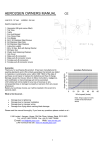
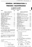
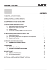
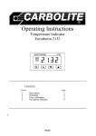
AERO4GEN OWNERS MANUAL
LVM 412 : 12 Volt
CE
LVM424 : 24 Volt
PARTS CHECK LIST
1 : Generator (M8 grub screws fitted)
1 : Tail Tube
1 : Tailfin
1 : Fan Hub Bossed
1 : Fan Clamp Plate
6 : Fan Blades
1 : Hub Cover
6 : M6 X 25 Stainless Steel Screws
6 : M6 Stainless Steel Nyloc Nuts
6 : M6 Stainless Steel Washers
3 : M4 X 25 Stainless Steel Screws
3 : M4 Stainless Steel Nuts
3 : M4 Stainless Steel Washers
1 : Allen Key 4 mm A/F
1 : Allen Key 5 mm A/F
1 : M6 X 20 Allen Bolt With Spring Washer
2 : Push fit connectors (Male)
2 : Push fit connectors (Female)
6 : M6 Black Nut Covers
Amps output @12v
Aero4gen Performance
20
15
10
5
0
0
10
20
30
40
50
Wind speed (knots)
Note: Amps Output of a 24V model will be half
shown above
Guarantee
Thank you for purchasing this product. It has been manufactured to exacting standards and LVM Limited guarantees that
should any defect in materials or workmanship occur within ONE YEAR of the date of purchase we will repair or replace the
defective part free of charge.
Damage caused by misuse, failure to follow instructions, negligence, and modification or transit damage will not be
warranted.
LVM Limited will not be liable for any loss of revenue or any consequential loss or damage to property or persons from any
cause whatsoever.
Retain your purchase invoice, as it will be needed in the event of a warranty claim.
What is Not Covered –
•
•
•
•
Damage due to lightening
Damage due to improper installation
Damage due to improper wiring
Damage from flying debris causing blade damage.
Please read the manual thoroughly. If you have any questions please contact us at –
LVM Limited, Aerogen House, Old Oak Close, Arlesey, Beds. SG15 6XD
Tel: +44 (0) 1462 733336 Fax: +44 (0) 1462 730466
E-mail: [email protected] Web: www.lvm-ltd.com
LVM Technical web site www.lvm.ltd.dial.pipex.com
1
60
MOUNTING
This Aero4gen is fitted with an aluminium bronze mounting adaptor which is designed to clamp onto a tube diameter of
1” (25.4mm)
1.5” (38mm)
LVM manufactures several mounting kits in marine grade stainless steel details of which are included in these instructions.
A minimum turning radius of 480mm should be allowed when selecting a position to mount the Aero4gen.
Great care should be taken to site the unit to avoid personal injury from the rotating blades.
When constructing a mounting system for the Aero4gen make sure it
can withstand the weight of the generator together with the additional
wind forces shown in the table opposite.
If the Aero4gen is to be mounted on a yacht/boat care should be taken
where to position it, as the Aero4gen will always produce a very slight
magnetic cogging vibration when rotating and an electrical vibration
whilst charging. This noise will obviously be greatly amplified if
mounted on a very hollow section of a yacht/boat.
Description of
wind
Gentle breeze
Moderate breeze
Fresh breeze
Strong breeze
Moderate gale
Fresh gale
Strong gale
Whole gale
Storm
Hurricane
Mean
velocity
in knots
9
13
19
24
30
37
44
52
60
68
Force
Lbs
Force
Kg
0.5
1.3
2.5
4.5
7
10.5
15
20.5
27
35
0.3
0.6
1.5
2
3.2
4.8
7
9.5
12.5
16
RADIO / RADAR / DECCA / SAT.NAV. INTERFERENCE
The Aero4gen should be mounted at least 1 Metres from any form of
aerial to avoid air born interference. The output cable from the
generator together with the dump regulator cables, if fitted, should be
routed at least 1 Metre from aerial cables. It is most important,
particularly on yacht installation, that the negative (-) return cable to the battery is clean and fully tightened. The safety cable
fitted around a yacht/boat is tensioned by a bottle screw or turnbuckle and this cable has been known to cause interference.
The remedy is to rope tension or use an insulated connector.
MIZZEN MAST MOUNTING – See page 9
ASSEMBLY
FAN BLADE ASSEMBLY
Assemble the fan using the M6 X 25 screws, M6 Nyloc Nuts and M6 Washers. The best way to assemble the fan is to lay
the Hub Clamp Plate on a flat surface, blade sockets upwards and then insert the 6 blades concave side (hollow side)
upwards. See Fig. 1. Then place the Bossed Hub on top locating the blades in the sockets. Insert the 6 off M6 screws,
washers and nuts, and at this stage only tighten the nuts sufficiently to lightly grip the blades. See Fig. 2. Turn each blade
until the indicator marks on the blade and hub align; this sets the blade angle. See Fig. 3. Then finally fully tighten the nuts,
and push on plastic nut covers.
NOTE: Do NOT install the fan assembly until the Aero4gen is mounted.
Fig 1.
Fig 2.
2
ALIGN MARKS
Fig 3.
Fig 4.
TAILFIN ASSEMBLY
Attach the tailfin onto the tail tube using the M4 X 25 long screws, washers, and M4 Nyloc nuts.
ELECTRICAL DATA
Aero4gen output wire colour Code - The Red output wire is POSITIVE (+)
The Black output wire is NEGATIVE (-)
Wire Rating - The output wires of the Aero4gen will require extending. Electrical systems lose energy from the resistance of
the wire size used. The larger the wire size the smaller the loss, however larger cross sectional area wire can be costly and
in some cases more difficult to source. The following table shows recommended wire sizes, they are based on a 3% and
5% energy loss at an average wind speed of 20knots. It is recommended a minimum wire size of 2.5 sq mm be used.
Single Wire Length
0 – 5 Metres
Voltage Drop (%)
12 volt Aero4gen
24 volt Aero4gen
3%
2
4.0 mm
2
2.5 mm
5%
2
2.5 mm
2
2.5 mm
6 – 10 Metres
3%
2
6 mm
2
2.5 mm
5%
2
4.0 mm
2
2.5 mm
11 – 20 Metres
3%
2
10 mm
2
4.0 mm
5%
2
6.0 mm
2
2.5 mm
2
Useful wire cross sectional area mm conversion to AWG
2
2
2
2.5 mm = 14 AWG
4.0 mm = 12 AWG
6.0 mm = 10 AWG
2
10.0 mm = 8 AWG
If the Aero4gen is connected directly to the battery terminals we recommend a 20 Amp fuse for 12V Models and a 15 Amp
fuse for 24v Models is fitted in the red (positive) wire from the generator to the battery, so that if a dead short occurred it
would prevent serious damage to the wiring and the generator.
The RED OUTPUT WIRE output is connected to the POSITIVE + terminal of the battery.
The BLACK OUTPUT WIRE to the NEGATIVE – terminal of the battery.
VOLTAGE REGULATION
The output wires of the Aero4gen can be connected directly to the terminals of the battery that requires charging, as shown
in Fig 5., however, if the terminal voltage of the battery is not continually monitored for over voltage (14.2v for 12v batteries)
and (28.4v for 24v batteries) the battery can be seriously damaged. Fitting an LVM voltage regulator will protect the battery
from becoming over charged. You may well have chosen a voltage regulator when purchasing the Aero4gen, but we would
recommend you look at page 15 SELECTING THE CORRECT LVM VOLTAGE REGULATOR to make sure you have
purchased the correct unit.
You may also consider installing an ammeter, voltmeter or an amphour meter – all are available from LVM, part number as
follows (LVM66) 0 –5A Ammeter, (LVM67) 0 –20A Ammeter, (LVM68) 0-30A Ammeter), (LVM69) 0-15v dc Voltmeter
(LVM200) Digital Amp Hour Meter
3
INSTALLATION
PLEASE FOLLOW THESE PRECAUTIONS DURING INSTALLATION
• Choose a calm day.
• Have someone available to help during installation.
• Do not install the blade assembly until the generator is mounted.
Whilst initially installing the generator, or carrying out future maintenance, it is important that the fan assembly is stationary.
1. Attach the push - on connectors and covers supplied to one end of your output cable. Observing polarity plug them into
the generator's output connectors.
2. Thread the output cable carefully through the centre of your mounting tube. If the bottom of the tube is not accessible a
hole must be drilled to enable the cable to be brought out. Be sure to leave enough slack in the cable so that if
necessary the generator can be removed.
3. Locate the generator on top of your mounting tube, and then fully tighten the M8 clamp bolt nut on the adaptor.
4. The tail assembly can now be inserted into the hole at the top of the generator ensuring that the tailfin is positioned
vertically and tighten the M8 grub screws.
5. Fitting the fan blade assembly onto the main shaft of the generator.
Grease fan hub bore then fit the fan assembly onto the generator main shaft aligning the M6 clearance hole in the fan
hub boss with the M6 tapped hole in the main shaft. Fit the M6 spring washer under the head of the M6 x 20 Socket
Cap Screw. Insert the bolt through the M6 clearance hole in the outer fan hub boss and fully tighten it into the main
shaft using the Allen key supplied (best to increase the leverage on the allen key by fitting a tube or something similar
to make sure it is fully tightened). See Fig. 4 the black hub cover is then pushed onto the hub boss.
6. The output wires are then connected to the battery. See Fig.5
The RED WIRE is connected to the POSITIVE + terminal and the BLACK WIRE
to the NEGATIVE - terminal. We recommend a 20 Amp fuse for 12V Models
and a 15 Amp fuse for 24v Models is fitted in the red (positive) cable from the
generator to the battery, so that if a dead short occurred it would prevent serious
damage to the wiring and the generator.
Note: Do NOT reverse the connections from the generator to the battery
(ie. Generator Positive to battery Negative and generator Negative to battery
Positive). Doing this will damage the rectifier and void your warranty.
WARNING THE AERO4GEN SHOULD NOT BE ALLOWED TO RUN OPEN
CIRCUIT. IN HIGH WINDS HIGH VOLTAGES WILL BE PRODUCED: THE
SUPPRESSION CAPACITORS CAN BE DAMAGED: THE FAN WILL TURN
FASTER SUFFERING UNNECESSARY STRESS
MAINTENANCE
The Aero4gen is designed to operate for long periods without needing any
maintenance. The life of the generator and its performance will be enhanced if
periodic inspection is carried out. For personal safety reasons before carrying out any
inspection make sure you stop the generator from rotating.
The following should be checked every 6 months.
• Check blades for damage and replace if necessary. Do not use the generator
with damaged or unbalanced blades. This will cause unnecessary wear and
possibly damage to the main bearings.
• Check the fan hub assembly for tightness.
• Check the mounting adaptor and your mounting system for tightness.
• Check all external electrical connections for tightness and corrosion.
• Wash down the generator with fresh clean water to remove debris and salt deposits that can build up.
If you experience a problem with your Aero4gen contact LVM to determine the nature of the problem, LVM will send you
replacement parts and instructions needed to repair the generator. In the event that the generator is returned for
repair/service you will be notified of the cost for carrying out the work and will incur the transport costs.
4
5
6
7
Aero4gen mounting kits
Mk2 Mounting kit includes –
MK4 Mounting kit includes –
MK6 Mounting kit includes - –
1x 1” O.D. Stainless steel tube 1200mm
long
1 x 1” Stanchion mount base
1 x 1” to 1" Universal plate
1 x 1.5” Stainless steel tube
1450mm long
1 x 1.5 Stanchion mount base.
1 x 1” to 1.5" Universal plate
1 x 1.5” O.D. Stainless steel tube
2,900mm long
1 x 1.5” Stanchion mount base
1 x 1” to 1.5" Universal plate
10 Metres of 4mm Dia. Stainless
steel wire rope
3 x Wire rope terminal/tensioners
3 x Wire rope terminals
3 x Deck ‘U’ bolts
2 x 1.5” U bolts
1 x 4 hole plate
8
KEY DIMENSIONS WHEN CONSTRUCTING A MIZZEN MAST MOUNTING
9
TROUBLE SHOOTING
The AERO4GEN is design to give many years of reliable service as it contains really only two moving parts and one
electronic component; they are the permanent magnet rotor, the slipring brush assembly and a rectifier.
The only parts that can wear are: Main bearing ball races, pivot shaft ball races, and the carbon brushes which make
contact with the sliprings. For safety reasons fan blades are designed to brake off if by accident an arm or hand is caught in
the fan.
SIMPLE TEST
A simple test to prove there is an output voltage from the generator can be carried out whilst the generator is in it's working
position. Disconnect the generators output cable from the battery, or the TB regulator if fitted. With the fan turning in the
wind and the two output leads open circuit, allow the fan to build up speed, then touch the two output leads together
(shorting them) the fan should noticeably slow down and act as a brake. If this does not happen, check that your extension
wire connection from the actual generators output cables are not corroded or have become disconnected. If there is a fuse
fitted in the output cable check it has not blown.
The above test can also be carried out by turning the generators main shaft by hand (any direction) to check the braking
action.
Note: Although the instruction sheets supplied with the generator warns you not to run the generator in an open circuit
condition the tests can be carried out safely at wind speeds of up to 20 knots.
(The reasons we do not recommend generators be left in an open circuit condition is that at very high wind speeds the
suppression capacitors maximum voltage may be exceeded and destroy them.
The following tools and equipment will be needed to carry out tests and repairs to the generator.
A multimeter which can read 0 - 100 volts DC, measure resistance, have a diode test, and a continuity (buzzer test).
Pozi drive screwdriver.
Circlip pliers.
Soldering iron and solder.
Hammer.
Piece of hardwood, and a brass rod 12mm diameter X 250mm long or similar.
For pivot bearing replacement, a bench vice will be required.
MEASURING OUTPUT VOLTAGE
With the generator in its operating position, disconnect the generators output cable from the battery or the TB regulator if
fitted, and attach a multimeter set on 0 - 100 volts dc range to the two output leads.
The following open circuit voltages should be obtained at the wind speeds shown below. It is most important that the wind
speed is measured at the same height the wind generator is mounted.
12v Model
6 knots = 12v 10 Knots = 25v 15 knots = 35v 20 knots = 47v
24v Model
6 knots = 24v 10 Knots = 50v 15 knots = 70v 20 knots = 94v
If you have a lathe or some other means of turning the main shaft at a known RPM a 12v model produces 0.06v per rev.
and a 24v model 0.12v per rev.
If no voltage is present, check that your extension wire connection from the actual generators output cables are not
corroded or have become disconnected. If there is a fuse fitted in the output cable check it has not blown. Check output
voltage again at the generators actual output cable. If there is still no voltage output, go to the instructions and tests listed
under heading NO OUTPUT.
REDUCED OUTPUT
Check blades are set at the correct angle, and the concave side (hollow side) of the blade faces the wind.
The main shaft of the generator should turn freely, however there will always be a slight resistance, which is called the
cogging effect. To check the starting torque/cogging effect of the generator is correct Sellotape 2 - 3 pound coins. (20 - 30
grams) on the tip of a blade. Set this blade by turning the fan till it is horizontal, let go of the blade and the fan should just
start to turn. If the fan turns ok as described above, then follow instructions under heading NO OUTPUT, with particular
attention to the rectifier test. If the fan did not turn as described in the test above, follow the instructions and tests listed
under headings KNOCKING/SCRAPING SOUND ONCE PER REVOLUTION, GENERAL MECHANICAL CONTINUOUS
NOISE, and NO OUTPUT.
10
NO OUTPUT
Remove the generator from mounting, taking off the tailfin and fan assembly. Remove the rear cover (6 off screws) and
hinge back cover. A component called a rectifier that converts the 3 Phase A/C output voltage of the stator into D.C volts is
mounted on the inside of the cover. (Note later models have also suppression capacitors soldered to the rectifier.)
Disconnect the 3 push fit connectors (output wires from stator) which are attached to the centre terminals of the rectifier. No
need to remember which order or terminal they come from, as they can fit on any of the 3 centre terminals.
Using a multimeter set on resistance measurement (ohms) check the resistance in turn of the of 3 output wires (in pairs)
from the stator. They should read 1.6 ohms 12v model, 6.5 ohms 24v model.
CHECKING A/C OUTPUT VOLTAGE OF STATOR
Set the multimeter to read A/C volts, attach test leads to the 3 off stator output wires (in pairs) then turn the main shaft of
the generator by hand (any direction) small voltage should be indicated on the multimeter.
Check the stator and suppression capacitors do not look burnt or overheated. Check tightness of stator retaining screws.
If at any time the generators output leads have ever been connected to battery terminals the wrong way round, or the
generator has been struck by lightening then the rectifier may be have been damaged.
RECTIFIER TEST
Readings taken of a Good Rectifier.
Set a multimeter to diode test, then check: 1. Disconnect all connectors from the rectifier.
2. Attach the red test lead from multimeter to the + plus terminal of the rectifier, attach the black test lead to the - negative
terminal. RESULT No Reading.
3. Reverse the test leads i.e. attach the red test lead to the - negative terminal of the rectifier then the black test lead to the
+ plus terminal. RESULT 0.8 - 0.9 volts
4. Connect the test leads to the 3 centre terminals of the rectifier
in pairs. RESULT No Reading.
Readings taken of a Faulty Rectifier.
1. Disconnect all connectors from the rectifier.
2. Attach the red test lead from multimeter to the + plus terminal of the rectifier, attach the black test lead to the - negative
terminal. RESULT 0 Volts
3. Reverse the test leads ie. attach the red test lead to the - negative terminal of the rectifier then the black test lead to the
+ plus terminal. RESULT 0 Volts
4.Connect the test leads to the 3 centre terminals of the rectifier in turn in pairs.
RESULT 0 Volts
If in doubt about the condition of the rectifier, replace with a new one. Refit the 3 off 3 phase stator output leads to the
centre terminals of rectifier.
Set the multimeter to read DC. volts. Attach the red test lead of the multimeter onto the + plus terminal of the rectifier, then
the black test lead onto the - negative terminal. Turn the main shaft of the generator by hand (any direction) this should
indicate a voltage on the multimeter. Refit Red and Black DC. output leads from the rectifier. Refit rear cover using a new
gasket make sure all wires are clear of the rotor.
CHECKING SLIPRINGS AND BRUSHES
Remove the brush cover assembly (4 screws). Hinge back brush cover assembly leaving the red and black wires attached.
Check the condition of the sliprings and clean them if necessary.
Check the spring-loaded carbon brushes are clean and are free to move in the brush holder.
Set a multimeter to continuity check (buzz test).
Check there is continuity between the top carbon brush and the positive + terminal of the rectifier, then check there is
continuity between the bottom carbon brush and the negative terminal of the rectifier.
Check there is continuity between the top slipring and the red output cable of the generator.
Then check there is continuity between the bottom slipring and the black output cable of the generator.
11
If no continuity is found on one or both output leads, check the soldered joint on the slipring. Resolder if necessary.
Set multimeter to read 0-15 volts DC connect test leads of multimeter to the brushes top brush is (Positive +) bottom brush
is (Negative -) turn generator main shaft by hand in any direction. If a voltage is present then refit brush cover using a new
gasket. Attach the test leads of the multimeter to the output wires of the generator, then turn main shaft again to check a
voltage is present.
KNOCKING/SCRAPING SOUND ONCE PER REVOLUTION
Whilst the generator is in it’s working position, check that the M6 allen screw which retains the fan assembly to the main
shaft is fully tightened. Also check tightness of all other fasteners on the fan assembly, mounting adaptor and tailfin.
Remove rear cover and check the condition of the rotor, it may be rubbing on the stator.
Inner main bearing could be worn, check for axial and radial movement. Check the tightness of the 4off M5 stator retaining
screws, this can cause a noise if slightly loose.
GENERAL MECHANICAL CONTINUOUS NOISE
Remove fan and check axial and radial play in the main front bearing. Remove rear cover and check inner main bearing in
the same manner. If large amount of play is found replace main bearings.
Follow instructions listed REPLACING MAIN BEARINGS.
GENERAL ELECTRICAL VIBRATION NOISE
It is normal for the Aero4gen to produce a very slight magnetic cogging vibration when rotating, and an electrical vibration
whilst charging. This noise will be greatly amplified if the Aero4gen is mounted on a very hollow section of a yacht/boat. If
mounted directly over sleeping quarters it may well be necessary to stop the Aero4gen at night.
Well-known methods that can reduce vibration noise are listed below.
1. Rubber mount as many fixings within the system as possible.
2. Insert round insulation material (the type you fit around cold water pipes to stop them freezing during winter) into the bore
of the 1.5" mounting tube. (15mm pipe sized insulation normally fits just perfect).
3. Coil a length of rope around the outside diameter of the mounting tube (full length).
SLIGHT ELECTRIC SHOCK FROM HAND RAIL
Remove the generator from mounting, taking off the tailfin and fan assembly. Remove the rear cover (6 off screws) and
hinge back cover. Using a multimeter set on continuity/buzzer test, check the 3 Phase output wires from the stator assembly
do not have continuity with the main casting.
i.e. The casting/main housing of the generator should be totally isolated from the electrical output of the generator.
If they do have continuity a new stator assembly must be fitted - contact LVM.
REPLACING PIVOT BEARINGS
Remove the generator from it's mounting, taking off the tailfin and fan assembly. Remove adaptor (M8 grub screw), and
brush cover. Remove bottom cover (2 screws).
Clamp the pivot shaft in a vice, using jaw protectors so as not to damage the pivotshaft. Then using a hammer against a
piece of wood to protect the casting paintwork, tap out pivotshaft assembly by hitting the base of the casting.
The bearings can now be removed from the pivotshaft. Use Loctite bearing fit when refitting the new bearings to the pivot
shaft, and to the generator housing. Apply silicone sealant to the bottom cover, and the output wires within the adaptor when
reassembling the pivot shaft assembly. Refit brush cover using a new brush cover gasket.
12
ELECTRICAL COMPONENT DIAGRAM OF AERO4GEN
ELECTRICAL SCHEMATIC DIAGRAM OF AERO4GEN
SUPPRESSION CAPACITORS
1uF
250v
1uF
250v
3 PHASE STATOR WINDING
3 PHASE STATOR WINDING
STAR CONNECTED
STAR CONNECTED
RESISTANCE OF EACH PHASE
12v MODEL = 1.6 OHMS
24v MODEL = 6.5 OHMS
~
1uF
250v
COLOUR OF STATOR
OUTPUT LEADS
12v - BLACK
24v - RED
1uF
250v
~
~
~ ~ ~
+
-
~
~
~
-
3 PHASE
RECTIFIER
SPRING
3 PHASE RECTIFIER
S20VT80
+
+ POSITIVE SLIPRING
+ POSITIVE SLIPRING
- NEGATIVE SLIPRING
- NEGATIVE SLIPRING
SOLDERED CONNECTION
BRUSH CAP
ASSEMBLY
CARBON BRUSHES
CARBON BRUSH
PIVOT SHAFT
OUTPUT WIRES
OUTPUT WIRES
13
INSTRUCTIONS FOR REMOVING AND REPLACING MAIN BEARINGS (AERO4GEN)
Parts required:
2 off - Main bearings
LVM Part No. Bearing 783
1 off - Rear cover gasket
LVM Part No. Gasket 548
2 off - Circlips 15mm
LVM Part No. Circlip 862
6 off - Rear cover retaining screws
LVM Part No. Screw 664
1 off - Small amount of Loctite 638 in tube.
Tools required: Hammer, Circlip pliers, Pozi drive screwdriver, Piece of hardwood, and a brass rod 12mm diameter X
250mm long or similar.
1. Disconnect output leads, and remove generator from mast. Remove fan, and tailfin assembly.
2. Remove the front circlip on the main shaft.
3. Remove 6 off self-tapping screws retaining the rear cover.
4. Place a piece of hard wood on a concrete floor. Holding the generator with the rear cover held back and main shaft
downwards, lift and force downwards the generators main shaft onto the piece of hard wood. This should displace
the main shaft inwards. Alternatively the main shaft can be pressed out, or hammered out, but take care not to bruise
the end of main shaft.
5. The main shaft/ rotor assembly should now have moved inwards into the main housing.
6. Using a piece of brass rod, or similar, so as not to damage the end of the main shaft - tap the shaft through both the
bearings and remove rotor assembly from the rear of the main housing.
7. Having removed the rotor from casting. Check the main shaft for wear, particularly the areas the main bearings are
positioned. If the shaft wear is found to be excessive a new shaft will have to be fitted. Contact LVM Ltd.
8. Using the brass rod and a hammer knock out the main bearings from the casting.
9. Refit new main bearings using a little Loctite Bearing Fit smeared on the O.D. of the bearings.
10. Clean the main shaft, then clean the rotor magnet with sellotape (sticky side) to remove small pieces of steel pickup.
11. Smear a little Loctite Bearing Fit onto the main shaft close to the rotor, and in the bore of the outer main bearing.
12. Insert the main shaft/rotor assembly into the generator main bearings. WARNING! The rotor magnets are very powerful
and will quickly draw the assembly into the stator. When the main shaft/rotor assembly is fully inserted check it rotates
without rubbing.
13. Smear a little Loctite Bearing Fit on the outer main bearing inner race to shaft. i.e. between the O.D. of the shaft and the
I.D. of the inner race. Push the main shaft in and out a little to spread the Loctite between the outer main bearings bore
and the main shaft.
14. Fit new circlip
15. Refit rear cover using a new gasket, make sure all internal wiring is clear of the rotor.
14
SELECTING THE CORRECT LVM VOLTAGE REGULATOR
The output of the Aero4gen can be simply connected directly to the terminals of the battery that requires charging, however,
if the terminal voltage of the battery is not continually monitored for over voltage (14.2v for 12v batteries) and (28.4v for 24v
batteries) the battery can be seriously damaged. Fitting an LVM voltage regulator will protect the battery from becoming
over charged.
TEMPERATURE COMPENSATION - This additional feature is available on all LVM regulators. If the battery is located in a
building where the ambient temperature is always around 20 deg.C then standard regulators can be used. However if you
intend to locate a battery where temperatures may go down to freezing and perhaps rise to tropical temperatures then you
should install a regulator that is fitted with a temperature compensation circuit. This automatically allows the battery to be
charged at a higher voltage as the temperature drops, and a lower voltage if the temperature increases. Simply add (-T)
after the LVM Product No. ie. 4SB12 –T.
There are two types of regulator suitable for the Aero4gen –
1.
Single battery regulator - LVM Product No. 4SB12, 4SB24 - These units are simply connected to
the battery terminals, and if the battery voltage reaches 14.2v (12v systems) or 28.4 (24v systems) the regulator
diverts power to a high wattage wire wound dump resistor. This regulator should NOT be used if you have any other
form of charging system connected to the battery ie. Mains charger/ shore power, engine driven alternator.
THESE REGULATORS ARE NOT SUITABLE FOR YACHT INSTALLATIONS.
Note: These regulators draw a continuous small standby current of around 10mA – 15mA.
2.
Twin battery regulators – LVM product No. 4TB12, 4TB24 - These units are connected between the output of the
Aerogen, Aquagen or Solargen module and the battery terminals. They control the actual output voltage of Aerogen,
Aquagen or Solargen by diverting power to a high wattage wire wound dump resistor when their output voltage
reaches 14.2v (12v systems) or 28.4 (24v systems). They have two schottky blocking diodes built into the regulator
which enables them to monitor and control the charge to two batteries totally independent of each other, therefore
making it ideal for separate charging of engine starting and domestic batteries. The battery with the lowest terminal
voltage will be charged first, then gradually when both batteries become fully charged the Aerogen, Aquagen or
Solargen modules output is automatically diverted to the dump resistor, this does two things it stops the batteries over
charging and keeps the generator always on load.
Note: These regulators draw NO standby current from the battery.
THESE REGULATORS ARE SUITABLE FOR YACHT INSTALLATIONS
Also available from LVM are Diode Units – LVM product No. 4DU, 6DU
The 4DU when combined with a 2TB or 4TB regulator enables one additional battery to be charged.
The 6DU when combined with a 4TB regulator enables two additional batteries to be charged.
The Aero4gen and a Solargen modules output may often be combined, the table below shows the recommended regulator
for various systems. Note: Two batteries wired in parallel are classed as one independent battery. Having selected the
recommended regulator model from the table simply add the voltage required ie. 4TB12 for a 12v system or 4TB24 for a 24v
system. Basic wiring diagrams are shown on page 18. If you cannot find your particular system or application within the
table or require full wiring diagrams please check our web site www.lvm-ltd.com or call our sales office who will e-mail, fax or
post you copies.
VOLTAGE REGULATOR TABLE
Number of independent batteries to be charged
SYSTEM
1 x Aero4gen
1 x Aero4gen + 5w Solargen panel
1 x Aero4gen + 10w Solargen panel
1 x Aero4gen + 17w Solargen panel
1 x Aero4gen + 25w Solargen panel
1 x Aero4gen + 35w Solargen panel
1 x Aero4gen + 50w Solargen panel
1 x Aero4gen + up to 60w Solargen panels
1
2
3
4
4SB or 4TB
4SB or 4TB
4SB or 4TB
4SB or 4TB
4SB or 4TB
4SB or 4TB
4SB or 4TB
4SB or 4TB
4TB
4TB
4TB
4TB
4TB
4TB
4TB
4TB
4TB + 4DU
4TB + 4DU
4TB + 4DU
4TB + 4DU
4TB + 4DU
4TB + 4DU
4TB + 4DU
4TB + 4DU
4TB + 6DU
4TB + 6DU
4TB + 6DU
4TB + 6DU
4TB + 6DU
4TB + 6DU
4TB + 6DU
4TB + 6DU
15
16