1
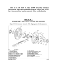
33 through 86 Series
General Information
0-1
GENERAL INFORMATION &
PERIODIC MAINTENANCE
33 THROUGH 86 SERIES
CONTENTS OF SECTION 0
Subject
Page
Page
PERIODIC MAINTENANCE
GENERAL INFORMATION
1966 MODEL IDENTIFICATION
BODY AND STYLE NUMBER
1966 MODEL DESIGNATION
VEHICLE IDENTIFICATION
NUMBER PLATE
STARTING VEHICLE IDENTIFICATION
NUMBERS
ENGINE UNIT NUMBER
ENGINE IDENTIFICATION CHART
TRANSMISSION SERIAL NUMBER
DIFFERENTIAL RATIOS
TIRE INFORMATION
STARTING CAR WITH
BATTERY FAILURE
TOWING DATA
HOISTING THE CAR
GENERAL SPECIFICATIONS
1966 PAINT SERVICE NUMBERS
CAPACITIES
FACTORY INSTALLED
OPTIONAL EQUIPMENT
Subject
0-1
0-1
0-2
0-3
0-3
0-4
0-5
0-6
0-7
0-8
0-10
0-10
0-10
0-11
0-11
0-13
0-13
ENGINE CRANKCASE OIL
0-14
OIL FILTER
0-14
CRANKCASE VENTILATION FILTER . . . 0 - 1 5
POSITIVE CRANKCASE VENTILATION
VALVE
0-15
AIR INJECTION REACTOR FILTER . . . . 0-15
DISTRIBUTOR
0-15
RECOMMENDED OIL CHANGE INTERVAL. 0-15
CRANKCASE CAPACITY & OIL LEVEL . . 0-15
AIR CLEANER
0-16
TURBO HYDRA-MATIC TRANSMISSION . . 0-16
POWER STEERING GEAR & PUMP . . . . 0-17
DIFFERENTIAL
0-17
FRONT SUSPENSION AND
STEERING LINKAGE
0-17
SERVICE BRAKES
0-18
BATTERY
0-18
COOLING SYSTEM
0-18
SPEEDOMETER CABLE
0-19
BODY LUBRICATION POINTS
0-19
MAINTENANCE CHART
0-23
1 9 6 6 MODEL IDENTIFICATION
BODY A N D STYLE NUMBERS
A five digit number, called the car series and
body style designation number, identifies any car
as to series and style. Reading from left to right,
the digits represent the following:
The body and style numbers are stamped on a
plate and is mounted on the left upper cowl. (Fig.
0-1)
Information on this plate shows:
The first digit indicates the General Motors
Division.
The second and third digits are Fisher Body
Shell Designation. The third digit also is used to
designate the L-6 or V-8 engine (odd numbers
indicate L-6 and even, V-8 engine).
The fourth
designation.
and fifth
digits are body
style
1. Style Number
2. Body Number
3. Trim Number
4. Paint Number (Color Specification)
5. Accessories
6. Time Built Code
All Fisher Body numbers are prefixed by a
letter or letters indicating the plant at which the
body was assembled.
F-85 bodies are coded as follows:
LAN - Lansing
BF - Fremont
EXAMPLE: 3 3 3 07
—Club Coupe
•Standard F-85 Series
With L-6 Engine
GM Division (Oldsmobile)
All 88 and 98 series are coded as follows:
LAN - Lansing
BA - Doraville
BK - Kansas City
BL - Linden
BC - South Gate
All 98 series will be assembled at Lansing.
0-2
General Information
33 through 86 Series
1966 MODEL DESIGNATION
Series
Body Description or Name
Chassis
Designation
Body
Code
Sales and
Scheduling
Code
33300
Standard F-85
L-6 Engine
Club Coupe
Station Wagon - Two Seat
Four Door Sedan
33307
33335
33369
07
35
69
3307
3335
3369
33400
Standard F-85
V-8 Engine
Club Coupe
Station Wagon - Two Seat
Station Wagon - Two Seat Extended
Station Wagon - Three Seat Extended
Four Door Sedan
33407
33435
33455
33465
33469
07
35
55
65
69
3407
3435
3455
3465
3469
33500
Deluxe F-85
L-6 Engine
Hardtop Coupe
Station Wagon - Two Seat
Four Door Sedan
Four Door Hardtop Sedan
33517
33535
33569
33539
17
35
69
39
3517
3535
3569
3539
33600
Deluxe F-85
V-8 Engine
Hardtop Coupe
Station Wagon - Two Seat
Four Door Sedan
Four Door Hardtop Sedan
33617
33635
33669
33639
17
35
69
39
3617
3635
3669
3639
33800
Cutlass F-85
V-8 Engine
Coupe
Hardtop Coupe
Convertible
Custom Station Wagon - 2 Seat Ext.
Custom Station Wagon - 2 Seat Ext.
Four Door Hardtop Sedan
Four Door Sedan
33807
33817
33867
33855
33865
33839
33869
07
17
67
55
65
39
69
3807
3817
3867
3855
3865
3839
3869
35200
Jetstar 88
Holiday Coupe
Holiday Sedan
Celebrity Sedan
35237
35239
35269
37
39
69
5237
5239
5269
35400
Starfire
Hardtop Coupe
35457
57
5457
35600
Dynamic 88
Holiday Coupe
Holiday Sedan
Convertible
Celebrity Sedan
35637
35639 '
35667
35669
37
39
67
69
5637
5639
5667
5669
35800
Delta 88
Holiday Coupe
Holiday Sedan
Celebrity Sedan
Convertible
35837
35839
35869
35867
37
39
69
67
5837
5839
5869
5867
38400
Ninety-Eight
Holiday Sports Coupe
Holiday Sports Sedan
Convertible
Town Sedan
38437
38439
38467
38469
37
39
67
69
8437
8439
8467
8469
38600
Ninety-Eight
Luxury Sedan
38669
69
8669
Model identification in the following sections will use the Sales and Scheduling Code.
33 through 86 Series
General Information
0-3
VEHICLE IDENTIFICATION NUMBER PLATE
The 1966 vehicle identification number plate is
located on the left front door pillar as illustrated
in Fig. 0-2.
The plant sequential number starts with 100001
at each plant and will be in sequential order r e gardless of series prefix. Each unit number is
prefixed by a letter and six numbers which have
designations as shown in Fig. 0-3.
Fig. 0-1
Body and Style Number Plate
STARTING VEHICLE IDENTIFICATION NUMBERS
(Example Numbers)
Series
Plant Letter "M* Plant Letter " Z "
Units Built at
Units Built at
Lansing, Mich. Fremont, Calif.
33300
Std. L-6
333076M100001
333076Z100001
Std. V-8
334076M100002
334076Z100002
33500
Deluxe L-6
335176M100003
335176Z100003
33600
Deluxe V-8
336356M100004
336356Z100004
33800
Cutlass V-8 338676M100005
338676Z100005
33400
Fig. 0-2
Vehicle Identification Number Plate
STARTING VEHICLE IDENTIFICATION NUMBERS
(Example Numbers)
Plant Letter
" E " Units
Built at
Linden, N. J.
Plant Letter
" C " Units
Built at
Southgate,
California
Plant Letter
" M " Units
Built at
Lansing, Mich.
Plant Letter
" D " Units
Built at
Atlanta, Ga.
Plant Letter
" X " Units
Built at
Kansas City,
Kansas
35200
Jetstar 88
352376M100006
352376D100006
352376X100006
352376E100006
352376C100006
35400
Starfire
354576M100007
354576D100007
354576X100007
354576E100007
354576C100007
35600
Dynamic 88
356376M100006
356376D100008
356376X100008
356376E100008
356376C100008
35800
Delta 88
358376M100009
358376D100009
358376X100009
358376E100009
358376C100009
38400
Ninety-Eight
384376M100010
Series
m m T ONT ,Y IN LANSING PLANT
38600
Ninety-Eight
Luxury
386696M100011
0-4
General Information
33 through 86 Series
3 3 3 0 7 6 M 100001
Plant Sequential Number
Plant (Lansing)
Model Year (1966)
Body Type (Coupe)
•Engine Type (Odd No. = L-6
Even No. = V-8)
Series (Std. F-85)
Division (Oldsmobile)
Fig. 0-3
Vehicle Identification Plate Data
ENGINE UNIT NUMBER
(For Manufacturing and Service Use)
The L-6 engine has a DATE-CODE stamped on
the right side of the engine block, directly to the
r e a r of the distributor. (Fig. 0-4)
The date code consists of a_ letter, four digits
and two letters. The first letter stands for source
identification. The first two digits show the month
and the second two digits show the day the unit
was built. The last two letters show transmission or option usage.
EX.:
F or T 0 7 12 VE
Fig. 0-4
L-6 Engine Unit Number Location
Engines used in all other series (35400 through
38600) have an " M " prefix for 2-bbl. and " N "
prefix for 4-bbl. carburetor equipped engines
with a starting unit number of 500001.
For engine usage, refer to Engine Identification
Chart.
I—Jetaway Equipped
— 12 - Day of Month
— July - Month
Source Code
(Tonawanda)
Source Code (Flint)
V-8 engines have the engine unit number
stamped on a machined pad at the front of the
right cylinder head. (Fig. 0-5)
V-8 engines used in F-85 Series (33400, 33600
and 33800) have a "W" prefix and the starting
unit number is 001001.
Engines in the Jetstar 88 Series (35200) have a
" X " prefix and also have a starting number of
001001.
tt
Engines in "442" series have a " V " prefix and
have a starting unit number of 100001.
Fig. 0-5
V - 8 Engine Unit Number Location
33 through 86 Series
General Information
0-5
ENGINE IDENTIFICATION CHART
Engine Unit Number
Series
Prefix
Code
Letter
Starting
Unit
Number
Suffix
Code
Letter
Engine
Color
Carb.
Type
Head
Gasket
Thickness
Comp.
Ratio
33300 & 33500 (F-85 L-6) With
Manual Transmission
Manual Transmission w/C 60
Manual Transmission w/C 60
& K 20
Manual Transmission w/K 20
Manual Transmission Export
F or T
F or T
0101
0101
VA
VB
Gold
Gold
1 bbl.
1 bbl.
.020"
.020"
8.5 :1
8.5 :1
F or T
F or T
F or T
0101
0101
0101
VD
VC
VJ
Gold
Gold
Gold
1 bbl.
1 bbl.
. 1 bbl.
.020"
.020"
.020"
8.5 :1
8.5 :1
7.25:1
Jetaway
Jetaway w/C 60
Jetaway w/C 60 & K 19 & K 20
Jetaway Export
F
F
F
F
0101
0101
0101
0101
VE
VF
VG
VK
Gold
Gold
Gold
Gold
1
1
1
1
bbl.
bbl.
bbl.
bbl.
.020"
.020"
.020"
.020"
8.5 :1
8.5 :1
8.5 :1
7.25:1
Gold
2 bbl.
.025"
9.0 :1
or
or
or
or
T
T
T
T
33400, 33600 & 33800
(F-85 V-8)
W
001001
33400, 33600 & 33800 (F-85
V-8 Export Low Comp.)
W
001002
E
Gold
2 bbl.
.025"
8.3 :1
33807, 33817, 33867 & L-74 &
L-76 Optional 3839-3869
W
001003
G
Gold
4 bbl.
.025"
10.25:1
All F-85 Series With Low
Comp. Export Option
W
001004
H
Gold
4 bbl.
.025"
8.3 :1
Low Comp. Domestic L-73 Opt.
W
001005
L
Gold
4 bbl.
.025"
9.0 :1
442 & L-77 & L-78 Opt.
V
100001
Bronze
4 bbl.
.025"
10.25:1
35200 (Jetstar 88 Std. V-8)
(High Comp.)
X
001001
Gold
2 bbl.
.025"
10.25:1
35200 (Jetstar 88 Low Comp.
V-8) (Export Option)
X
001002
E
Gold
2 bbl.
.025"
8.3 :1
35200 (Jetstar 88 Std. V-8) (High
Comp. L-74 or L-76 Option)
X
001003
G
Gold
4 bbl.
.025"
10.25:1
35200 (Jetstar 88 Low Comp.
V-8) (Export Low Comp. Option)
X
001004
H
Gold
4 bbl.
.025"
8.3 :1
35200 (Jetstar 88 Low Comp.
Domestic) (L-65)
X
001005
L
Gold
2 bbl.
.025"
9.0 :1
35600 & 35800 (Std. Comp.)
Dynamic 88 & Delta 88
M
500001
Red
2 bbl.
.025"
10.25:1
35600 & 35800 (Export Low Comp.)
M
500002
E
Red
2 bbl.
.025"
8.3 :1
35600 & 35800 Domestic Low
Comp. Option (L-65)
M
500003
L
Red
2 bbl.
.025"
9.0 :1
35400, 38400, 38600 & L-74
Option Std. Comp.
N
500004
Red
4 bbl.
.025"
10.25:1
Export Low Compression
N
500005
E
Red
4 bbl.
.025"
8.3 :1
35400 & L-75 & L-77 Option
N
500006
S
Red
4 bbl.
.025"
10.5 :1
0-6
General Information
33 through 86 Series
MANUAL TRANSMISSION IDENTIFICATION
Type of
Transmission
Series
Usage
Location of Date Code
or Serial Number Plate
Example
Std. 3-Speed
33300 thru
33800
Stamped on Rear Face of
Case on Right Hand Side.
S0703
Option in
33400, 33600
& 33800
Serial Number Plate on
Right Hand Side of Case.
H.D. 3-Speed
Standard in
442 and
All 88 Series
33300 thru
33800
&
35400 thru
35800 Series
Std.
4-Speed
Close
Ratio
4-Speed
Mandatory
with L-77 & L-78
Option
Same As
Above
Stamped on Right Hand Rear
Case Flange at Approximately
Centerline of Mainshaft
Bore.
HEGAF
010001
HEGAB
010001
P0703
JETAWAY TRANSMISSION
Transmission MODEL and CODE NUMBERS
are stamped on the servo cover as shown in Fig.
0-6.
EXAMPLE:
6 6 L C
0 0 1
First day of
production
Model LC (L-6
Usage)
-1966 Model Year
MODEL
SERIES OR ENGINE USAGE
LC
- L-6 in 33300 and 33500 Series
(Fixed Stator)
ML
- V-8 330 cu. in. 2 Bbl. in 33400,
33600 & 33800 S/W (Variable
Stator)
MK
- V-8 330 cu. in. 4 Bbl. in 33400,
33600 & 33800 except with L-77
or L-78 opt. (Variable Stator)
NJ
- V-8 400 cu. in. 4 Bbl. in all
Series with L-77 or L-78 option
(Variable Stator)
MT
- V-8 330 cu. in. 2 & 4 Bbl. in
35200 Series (Variable Stator)
Fig. 0-6
Jetaway Model and Date Code Location
33 through 86 Series
General Information
0-7
TURBO HYDRA-MATIC TRANSMISSION
On 54 through 86 series plus optional on 52
series, the Turbo Hydra-Matic serial number is
stamped on a plate located on the right side of
the case. (Fig. 0-7)
STARTING
SERIAL NO.
SERIES OR ENGINE
USAGE
66-OB-1001
5600, 5800, 8400 and 8600 Series
(2 & 4 Bbl. V-8 Except L-75 or
L-77 Equipped)
66-OD-1001
5400 Series and 4 Bbl. Starfire
Engine in 5800, 8400 and 8600
(V-8 With L-75 or L-77 Opt.)
66-OF-1001
All 5200 Series (V-8 2 and 4
Bbl.)
66-OE-1001
All 5400, 5600, 5800, 8400 and
8600 Series With Heavy Duty
Transmission (V-8 2 & 4 Bbl.)
Fig. 0-7 Turbo Hydra-Matic Serial Number
Plate Location
DIFFERENTIAL RATIOS
The differential ratio code letters (1/4" high)
are stamped on the right rear inboard side of the
axle housing tube. (Fig. 0-8)
Letters, for both standard and Anti-Spin differentials, indicating corresponding ratio for each
series are shown in the following table:
Code L e t t e r s
Std. T y p e Diff.
With With
With
J - 5 6 Y-75 J - 5 6 & Y-75
Code L e t t e r s
Anti-Spin Type Diff.
Std.
With With
With
Equip. J - 5 6
Y-75 J - 5 6 & Y-75
Gear
Ratio
No.
Gear
Teeth
3300
Thru
3800
Except
Station
Wagons
2.78
3.08
3.23
3.55
3.90
39:14
40:13
42:13
39:11
39:10
SA
SC
SE
SI
TG
SK
SQ
SV
SX
TJ
SB
SD
SF
SJ
TH
SL
SR
SW
SZ
TK
Station
Wagons
(3455-65
3855-65)
3.08
3.23
3.55
40:13
42:13
39:11
SM
SO
su
SG
TC
TE
SN
SP
SY
SH
TD
TF
2.78
3.08
3.23
39:14
40:13
42:13
RA
RC
RE
QV
RI
RK
RB
RD
RF
QU
RJ
RL
5400
5600
&
5800
(*Only on
5600 & 5800
Series)
2.73
2.93
3.08
3.23
3.42
41:15
41:14
40:13
42:13
41:12
QA
QC
QE
QG
QI
*RO
*RQ
*RS
*RU
*RW
QB
QD
QF
QH
QJ
*RP
*RR
*RT
*RV
*RX
8400
&
8600
2.73
3.08
3.23
3.42
41:15
40:13
42:13
41:12
QK
QM
QO
QQ
RO
RS
RU
RW
QL
QN
QP
QR
RP
RT
RV
RX
Series
5200
Std.
Equip.
*QS
*RY
*QT
*RZ
0-8
General Information
33 through 86 Series
When the car is driven a few miles, tires warm
up causing pressure increase. If tire pressures
are checked when tires are warm, they may be up
to 6 pounds higher than the pressures shown on
the chart.
For continuous high speed operation, increase
tire pressure (cool) 4 pounds over the above
recommended inflation pressures, up to a maximum of 32 pounds for 4-ply rating tires, or 40
pounds for 8-ply rating tires.
Over inflation at light loads will have an adverse effect on the car ride and tire tread wear
pattern. Under inflation will promote heat and
abnormal wear.
Fig. 0-8
Differential Ratio Code Location
VEHICLE LOAD CAPACITY AND DISTRIBUTION
TIRE INFORMATION
Full Load Capacity Is:
The factory installed tires are selected to p r o vide the best all around tire performance for
normal operation.
They are also designed to operate satisfactorily
with loads up to and including the full rated load
capacity when inflated as recommended in the
following tire inflation pressures table.
INFLATION PRESSURES
To insure the proper tire inflation, follow the
recommendations in the tire inflation pressures
table. Keep tires properly inflated, and check
inflation pressures periodically. This will insure
best tire life and riding comfort, over the full
range of driving conditions.
RECOMMENDED COOL TIRE INFLATION
PRESSURES - POUNDS PER SQUARE INCH
Average
Load
Tire
1 to 5
Ply
Passengers
Rating
(Normal
Inflation)
Over 4
Passengers
To Full
Rated Load
(Maximum
Inflation)
Front Rear Front
Rear
All Models Except
Station
Wagons
4
8
24
24
24
24
24
24
32
40
Station
Wagons
4
8
24
24
28
28
24
24
32
40
For intermediate loads, between average and
full rated capacity, tire inflation pressures should
be adjusted proportionally.
All Models - 1100 Lbs. 3 Passengers front seat
Except
Total:
3 Passengers r e a r seat
Station
200 Lbs. luggage
Wagons
Station
Wagons
2 Seat
1200 Lbs. 3 Passengers front seat
Total:
3 Passengers r e a r seat
300 Lbs. luggage
Station
Wagons
3 Seat
1200 Lbs. 3 Passengers
Total:
3 Passengers
seat
2 Passengers
or 300 Lbs.
front seat
second
third seat
luggage
When towing trailers, the allowable passenger
and cargo load must be reduced by an amount
equivalent to the trailer tongue load on the trailer
hitch.
OPTIONAL OVERSIZE A N D
8-PLY RATING TIRES
Oversize or 8-ply rating tires are not necessary for passenger car normal requirements.
However, an extra margin of tire serivce i s
available when these options are used at loads up
to and including full rated load.
On all Oldsmobiles except Station Wagons and
Vista-Cruisers, optional oversize 4-ply rating
tires are available (cars with factory installed
air conditioning are already equipped with larger
tires). Eight-ply tires are optional on all models.
In either case, these tires are applicable to
extended operation at or near full rated load or
for trailer towing when an extra margin of s e r vice is desired. However, use of a larger tire
or an 8-ply rating tire should not be construed as
permitting an increase in the full rated vehicle
load over that specified in the table.
33 through 86 Series
General Information
0-9
TIRE ROTATION
Reduced tire life due to excessive wear can be
caused by extra turning and cornering which is
required in city driving, high speed entering and
exiting on freeway interchanges, rapid acceleration, quick stops, and heavy loading. To obtain
uniform wear and extend tire life, rotate all five
tires at least every 6,000 miles in accordance
with Fig. 0-9. Also keep tires balanced, the front
wheels aligned, and periodically examine your
tires for unusual wear or damage.
Fig. 0-9
Tire Rotation
TIRE SIZES
Series
Without
Air Conditioning
With
Air Conditioning
F-85
L-6 Except Station Wagons
Standard Size . . . . ,
Oversize Option . . . ,
8-Ply Rating Option . ,
6.95-14
7.35-14
7.75-14
7.35-14
Not Available
7.75-14
F-85
V-8 Except Station Wagons
Standard Size . . . . . .
Oversize Option . . . ,
8-Ply Rating Option . ,
7.35-14
7.75-14
7.75-14
7.75-14
Not Available
7.75-14
F-85
L-6 and V-8 Station Wagons
Standard Size
Oversize Option . . . .
8-Ply Rating Option . .
7.75-14
Not Available
7.75-14
7.75-14
Not Available
7.75-14
Vista-Cruiser and Custom
Vista-Cruiser
Standard Size . . . .
Oversize Option . .
8-Ply Rating Option
8.25-14
Not Available
8.25-14
8.25-14
Not Available
8.25-14
Jetstar
Standard Size . . . .
Oversize Option . .
8-Ply Rating Option
7.75-14
8.25-14
7.75-14
8.25-14
Not Available
8.25-14
Dynamic
Delta 88 &
Starfire
Standard Size . . . .
Oversize Option . .
8-Ply Rating Option
8.25-14
8.55-14
8.25-14
8.55-14
Not Available
8.55-14
Ninety- Eight
Standard Size . . . .
Oversize Option . .
8-Ply Rating Option
8.55-14
8.85-14
8.55-14
8.85-14
Not Available
8.55-14
AH tires listed are 2-ply - 4-ply rating unless otherwise stated.
J
0-10
General Information
33 through 86 Series
STARTING CAR W I T H BATTERY FAILURE
JETAWAY AND TURBO
HYDRA-MATIC EQUIPPED
Jetaway and Turbo Hydra-Matic transmissions
are designed so that in the event of battery
failure, the engine cannot be started by pushing
the car. To start the car when the battery has
failed, use an auxiliary battery with jumper
cables.
Be sure to observe correct polarity when connecting the auxiliary battery to prevent possible
damage to the diodes in the Delcotron generator
charging unit.
MANUAL TRANSMISSION EQUIPPED
position at speeds up to 45 MPH, for distances up
to 50 miles. For higher speeds, longer distances,
or if the transmission has become damaged or has
lost fluid, it is recommended that the car be
towed with the rear wheels off the ground or the
propeller shaft disconnected at the differential
and secured to the frame or exhaust pipe. If the
car is towed with the r e a r wheels off the ground,
the steering wheel should be centered and lashed
to the window division channel or held in centered
position with a steering clamp. The car should
not be lifted more than six inches off the ground
or towed at speeds above 45 MPH. When towing
with the wheels off the ground, it is recommended
that a 4" x 4" timber be located beneath the
lower edges of the bumper to prevent lift chains
damaging the lower panel.
HOISTING THE CAR
To start the engine by pushing the car, move
the gearshift lever to high gear, depress the
clutch pedal, and turn on ignition switch. When
the vehicle reaches a speed of 10 MPH, release
the clutch pedal slowly.
When supporting car on a floor jack or floor
stand, the car should be supported at the suspension points only. Under no condition should
the car be supported at the extreme ends of
frame or on the frame side rail.
When using a frame contact type lift, position
the contact pads to lift the frame rails at points
shown in Fig. 0-10.
T O W I N G PRECAUTIONS
Except when the transmission, propeller shaft
or rear axle has become damaged or when the
transmission is low on fluid, the car may be
towed with the selector lever in the " N " (Neutral)
The car should not be lifted at the front or r e a r
bumper with anything other than the bumper jack
provided with the car.
LIFT POINTS
Fig. 0-10
Lift Points (Frame Contacts)
33 through 86 Series
General Information
0-11
GENERAL SPECIFICATIONS
F-85 Series
'(3300-3400-3500-3600 & 3800)
Standard
Station
Wagon
Series
VistaCruiser
442
All
Others
Jetstar
88
(5200)
All
Other
88's
(5400
5600
&
5800)
98's
(8400
&
8600)
Wheel Base
115"
120"
115"
115"
123"
123"
126"
Tread Width
Front
Rear
58"
59"
58"
59"
58"
59"
58"
59"
61.8"
63"
62.5"
63"
62.5"
63"
Overall Length
204.3"
209.5"
204"
204"
217"
217"
222.9"
Overall Width
75.3"
75.3"
75.4"
75.4"
80"
80"
80"
Overall Height
55.3"
58.3"
53.7"
Cutlaj 3s 4-Door Hardtop
54.5"
53.6"
55.5"
55.5"
55.8"
250
330
330
400
250
330
330
425
425
36
49.6
49.6
51.2
36
49.6
49.6
54
54
Engine Displacement
(Cu. In.) L-6
V-8
Taxable
Horsepower
L-6
V-8
EXTERIOR COLORS
Comb.
Code
A
B
C
D
E
H
J
K
L
M
N
R
T
V
w
Color Name
Du Pont
Stock No.
Rinshed-Mason
Stock No.
Ditzler
Stock No.
Ebony Black
Nocturne Mist
Provincial White
Lucerne Mist
Royal Mist
Laurel Mist
Forest Mist
Ocean Mist
Tropic Turquoise
Autumn Bronze
Burgundy Mist
Target Red
Sierra Mist
Almond Beige
Silver Mist
88
4622-L
4024-L
4630-L
4631-L
4633-L
4634-L
4628-L
4703-L
4707-L
4624-L
4625-L
4706-L
4401-L
4708-L
A-946
A-1709
A-1199
A-1720
A-1721
A-1716
A-1717
A-1718
A-1816
A-1817R
A-1711M
A-1712M
A-1821
A-1530
A-1819
9300
32448
8259
13042
13002
43391
43390
43364
43496
71525
50700
71472
22660
22270
32525
0-12
General Information
33 through 86 Series
INTERIOR COLORS
(SEMI-GLOSS)
Color
Du Pont
Stock No.
Rinshed-Mason
Stock No.
Ditzler
Stock No.
Parchment
Medium Slate (Met.)
Medium Green (Met.)
Medium Blue (Met.)
Medium Fawn (Met.)
Medium Red
Medium Turquoise (Met.)
Medium Bronze (Met.)
Black
Dark Slate
Dark Slate (Met.)
Midnight Green
Midnight Green (Met.)
Midnight Blue
Midnight Blue (Met.)
Midnight Fawn
Midnight Fawn (Met.)
Dark Maroon
Dark Turquoise
Dark Turquoise (Met.)
Dark Bronze (Met.)
9000-L
9269-L
4633-L
4630-L
9274-L
4625-LH
4628-L
9276-L
88
9321-LH
9270-L
9226-LH
4634-L
9320-LH
4631-L
9224-LH
9177-LM
9281-LM
9322-LH
9273-L
9277-L
62T82
66B13
65V32
65V22
66B83
65B52R
65B31
66B81
A946
166B15
66B14
66B37
65V33
166B16
65B26
166B74
165B80
66B65M
66B38
66B31
66B86
8360
32539
43367
13006
22696
71487
43400
22697
9248
32544
32540
43419
43399
13187
13047
22738
22572
50730
43534
43533
22698
Du Pont
Stock No.
Rinshed-Mason
Stock No.
Ditzler
Stock No.
9194-LH
4428-L
9285-L
9193-L
9192-L
9198-L
9293-LM
9287-L
9290-L
165B29
A946
66B12
65B35
65B28
65B87
66B64M
66B35
66B61M
13010
9317
32543
43369
13052
22533
50729
43532
22692
INTERIOR COLORS
(FLATS)
Color
Dark Blue (Met.)
Black
Dark Slate (Met.)
Midnight Green (Met.)
Midnight Blue (Met.)
Midnight Fawn (Met.)
Dark Maroon
Dark Turquoise (Met.)
Dark Bronze (Met.)
33 through 86 Series
General Information
0-13
CAPACITIES
F-85 Series
Item
Cooling System*
With Air Conditioning
Without Air Conditioning
L-6
(3300 & 3500)
V-8
(3400, 3600
& 3800)
Jetstar
88
(5200)
All Others
(5400 Thru
8600)
11.75 Qts.
11.75 Qts.
**
16.75 Qts.
16.25 Qts.
17.0 Qts.
16.5 Qts.
18.0 Qts.
17.5 Qts.
4 Qts.
5 Qts.
4 Qts.
5 Qts.
4 Qts.
5 Qts.
4 Qts.
5 Qts.
3.5 Pts.
3.5 Pts.
5 Pts.
2.25 Pts.
5 Pts.
2.25 Pts.
5 Pts.
2.25 Pts.
3 Qts.
9 Qts.
3 Qts.
9 Qts.
Engine Crankcase
With Filter Change
Manual Transmission
3-Speed (Std.)
3-Speed (Heavy Duty)
4-Speed
J eta way Transmission
Oil Pan Removed
Complete Overhaul
Turbo Hydra-Matic Transmission
Oil Pan Removed
Complete Overhaul
Power Steering
Pump Only
Complete System
3 Qts.
9 Qts.
4 Qts.
9 Qts.
4 Qts.
9 Qts.
1 Qt.
1.75 Qts.
1 Qt.
1.75 Qts.
1 Qt.
1.75 Qts.
1 Qt.
1.75 Qts.
Differential
3 Pts.
3 Pts.
3 Pts.
4.75 Pts.
Fuel Tank
20 Gal.
20 Gal.
25 Gal.
25 Gal.
•Without Heater - Subtract .75 Qts. on F-85's (L-6 & V-8)
- Subtract 1 Qt. on All Other Series
**442 Series - With A.C. - 17.75 Qts.
- Without A.C. - 17.25 Qts.
FACTORY INSTALLED OPTIONAL EQUIPMENT
The following list of factory installed options have been used in
numerous sections of this Service Manual. This list does not cover
all optional equipment but only the items which effect adjustments or
service procedures covered in this manual.
OPTION
CODE
DESCRIPTION
A-91
A-93
A-98
Vacuum Trunk Lid Latch
Vacuum Side Door Lock
Vacuum Rear Door Lock
B-01
B-07
Police Apprehender - City Cruiser
Police Apprehender - Highway Patrol
C-48
C-50
C-60
C-61
Delete Heater & Defroster
Rear Window Defroster
Air Conditioning
Air Conditioning with Automatic Controls
OPTION
CODE
G-51
G-67
G-69
G-80
J-50
J-56
K-19
K-20
DESCRIPTION
Heavy Duty Rear Springs
A u t o m a t i c S u p e r l i f t Rear Shock
Absorbers
Rear Stabilizer Shaft
Locking Type (Anti-Spin) Differential
Power Brakes
Heavy Duty Brakes (Police Usage)
Air Injection Reactor System (Calif. Cars)
Crankcase Ventilation - Closed Circuit
(Calif. Cars)
0-14
Periodic Maintenance
33 through 86 Series
FACTORY INSTALLED OPTIONAL EQUIPMENT (Cont'd.)
OPTION
CODE
DESCRIPTION
Throttle
Control
(Cruise
K-30
Automatic
Control)
L-65
Domestic Low Compression V-8 2- Bbl.
Engine
Domestic Low Compression V-8 4-Bbl.
330 Cu. In. Engine
High Compression V-8 Engine
High Compression Starfire V-8 Engine
High Compression V-8 Performance Engine (For B-01 or B-07) (Same as L-74
Except for Spark Plugs and Air Cleaner
Label)
High Compression V-8 Performance Engine (400 Cu. In. in F-85's) (Same as
L-76 Plus Dual Exhaust with 425 Cu. In.
Engine)
L-73
L-74
L-75
L-76
L-77
M-13
M-14
M-20
M-21
M-31
M-32
Heavy Duty F-85 Column Shift 3-Speed
Manual Transmission
Heavy Duty F-85 Floor Shift 3-Speed
Manual Transmission
Floor Shift 4-Speed Manual Transmission
Floor Shift 4-Speed Close Ratio Manual
Transmission
J eta way Trans, with Fixed Stator
Jetaway Trans, with Variable Stator on
L-77 or L-78 Opt. Engine
°ri!°rN
DESCRIPTION
CODE
M-33 Jetaway Trans, with Variable Stator (Except with L-77 & L-78 Engine Option)
M-34 Heavy Duty Jetaway with Variable Stator
with L-76 Engine
M-40 Turbo Hydra-Matic Transmission
M-41
Heavy Duty
Transmission
N-10
N-ll
Dual Exhaust System with L-73, L-74&
L-76
Dual Exhaust System with L-77 & L-78
T-87
Cornering Lamp
U-15
U-16
U-80
U-89
Safety Sentinel
Engine Tachometer
Rear Seat Speaker
Trailer Hauling Wire Harness
W-29
442 Performance Package
Y-75
Heavy Duty 15" Wheels, Hubs & Drums
(With B-07)
Heavy Duty Engine Cooling & Generator
Package
Y-76
Turbo
Hydra-Ma tic
PERIODIC MAINTENANCE
ENGINE CRANKCASE OIL
OIL FILTER
It is recommended that an oil be used which,
according to the label on the can, is (1) "intended
for service MS" and (2) " P a s s e s car makers'
t e s t s " or "Meets General Motors Standard
GM-4745M".
The full flow oil filter filters 100% of the oil
delivered by the pump. For this reason, the
interval or change is very important. The oil
filter should be changed every 6 months or 6,000
miles, whichever occurs first. Operating conditions may require more frequent replacement.
The proper oil viscosity to use depends on the
prevailing atmospheric temperature. The following chart will serve as a guide in selecting the
proper oil viscosity.
Lowest
Anticipated
Temperatures
SAE
Viscosity
Number
Above +32°F.
20W, 10W-30
32°F. to 0°F.
10W, 10W-30*
Below 0°F.
5W, 5W-20*
*5W-30 oil may be used at temperatures below freezing.
Fig. 0-11 Engine Oil Dip Stick
33 through 86 Series
Periodic Maintenance
0-15
Replace oil filter as follows:
A. Loosen filter with wrench, then remove and
discard filter.
B. Clean out filter body casting.
C. With new seal seated on face of new filter,
install filter and tighten to 17 ft. lbs.
D. Add oil, start engine and check for leaks.
CRANKCASE VENTILATION FILTER
( V - 8 ENGINES) OR CRANKCASE BREATHER
CAP (L-6 ENGINE)
Fig. 0-12
Jetaway and Turbo Hydra-Matic Dip Stick
At every oil change, more often under dusty
conditions, remove filter or cap, wash in kerosene
and re-oil with SAE 10W-30 oil.
than six thousand miles are driven in a 60-day
period, change oil every six thousand miles. Use
oil which, according to label on can, is intended
for service " M S " .
POSITIVE CRANKCASE VENTILATION VALVE
NOTE: When changing the oil during the fall
and winter seasons, consider the lowest anticipated temperature for the next 60 days. If the
temperature is expected to be occasionally below
0°F., 5W-20 oil is recommended. In areas where
the temperature will be consistently 0°F. or
below, 5W is recommended.
Ail Engines:
Once a year or every 12,000 miles (or at the
oil change period nearest to this interval) replace
the ventilation valve. The rest of the system
should be serviced at this interval by washing the
parts in kerosene and blowing out the hoses with
compressed air.
On the closed system, it is equally important
that the closing line from the valve cover to the
carburetor and the filter is also serviced.
SAE 5W oil is not recommended for sustained
high speed driving when the temperature is above
60°F.
SAE 30 oil may be used when the prevailing
daylight temperature is above 90°F.
AIR INJECTION REACTOR SYSTEM FILTER
Certain driving conditions, such as dust storms
and frequent driving on dusty roads, necessitate
more frequent oil changes.
The air injection reactor system filter, located
on the right side of the air cleaner, should be
serviced every 12 months or 12,000 miles under
normal operation.
If higher detergency is required to reduce
varnish and sludge formation, a thoroughly tested
and approved concentrate - "High Detergency
Concentrate" - is available.
To service filter element, remove element wash
in kerosene, dip in SAE 10W-30 oil and squeeze
to remove excess oil.
The use of " b r e a k - i n " oil, "tune-?up" compounds, "friction reducing" compounds, etc. in
Oldsmobile engines is specifically not recommended. However, excessive carbon build-up,
which may lead to detonation or engine "ping"
can be reduced by use of General Motors "Top
Engine Cleaner". Use only in accordance with
directions on the can label.
DISTRIBUTOR
The breaker cam should be lubricated * with a
thin film of Ball Bearing Lubricant every 12,000
miles or whenever the contact assembly is r e placed. No other lubrication is required.
RECOMMENDED OIL CHANGE INTERVAL
Change engine oil every 60 days even though
less than 1,000 miles have been driven. If more
When changing oil, drain the crankcase after
the engine has reached normal operating temperature to insure complete removal of the oil.
Oil pan drain plug torque is 40 ft. lbs.
CRANKCASE CAPACITY
Oil change only, 4 qts.
Oil and filter change, 5 qts.
0-16
Periodic Maintenance
33 through 86 Series
CHECKING AUTOMATIC TRANSMISSION
FLUID LEVEL—(Fig. O - l 2 )
OIL LEVEL
The engine oil dip stick located on the left side
of the engine, is marked " F u l l " and "Add". The
oil level should be maintained neither going above
the " F u l l " line nor under the "Add" line. The
oil level should be checked at every refueling and
oil added to maintain the proper level. (Fig.
0-11)
AIR CLEANER
Fluid level should be checked at the fluid filler
tube, located at the r e a r of the right exhaust
manifold, at each engine oil change interval.
Check must be made with the engine idling and
the selector lever in the " P a r k " position. Fluid
level must be maintained at the " F u l l " mark
(transmission warm).
Do not fill above " F u l l " mark as this will cause
foaming and will result in improper operation.
NON-DISPOSABLE TYPE (L-6 ENGINES)
DRAIN INTERVAL
At every 12 month period or 12,000 miles, more
often under dusty conditions, remove filter element, wash in kerosene, dip in SAE 10W-30 oil
and squeeze to remove excess oil.
DISPOSABLE ELEMENT TYPE
( V - 8 ENGINES)
This air cleaner incorporates a disposable air
filter element. Soft plastic flanges are used as
self-contained gaskets which seal the air cleaner
body and cover. Therefore, all air must pass
through the filter element.
The air filter element should be replaced every
24,000 miles under normal driving conditions, and
more frequently under dusty driving conditions.
Do not attempt to service the element.
The filter
follows:
element
should be replaced
as
A. Remove air cleaner assembly to prevent dirt
from falling into carburetor.
B. Remove filter
element from air cleaner.
C. Clean dust and dirt from metal surfaces of
air cleaner body and install new filter
element.
D. Install air cleaner assembly on carburetor.
Change fluid and filter (on Jetaway clean
strainer) at two years or 24,000 miles. Under
more severe service, change fluid and filter at
12,000 mile intervals.
DRAINING JETAWAY AND TURBO
HYDRA-MATIC TRANSMISSIONS
JETAWAY ( 3 3 0 0 THROUGH 5 2 0 0 SERIES)
A. Remove oil pan and permit fluid to drain.
B. Clean oil pan. Install new gasket and r e a s semble to transmission.
C. Add three quarts of fluid.
D. With the selector lever in " P a r k " position
and the car on a level surface, start engine.
With engine running, add fluid to bring level
to " F u l l " mark on dip stick.
Approximately three quarts of fluid are r e quired to fill the Jetaway transmission when the
fluid is drained by removing the pan. Nine quarts
are required after an overhaul.
TURBO HYDRA-MATIC
( 5 4 0 0 THROUGH 8 6 0 0 SERIES)
(OPTION O N 5 2 0 0 SERIES)
A. Remove oil pan and permit fluid to drain.
JETAWAY AND TURBO
HYDRA-MATIC TRANSMISSIONS
AUTOMATIC TRANSMISSION FLUID
Use only General Motors Automatic Transmission Fluid (Hydra-Matic Fluid) or fluids with the
following identification on the container: Brand
name, including the words "Fluid Type A" plus
the mark AQ-ATF -Number and Letter A embossed on the top of the can as follows: AQ-ATFNumber A".
B. Clean oil pan. Install new gasket and r e a s semble to transmission.
C. Add four quarts of fluid.
D. With the selector lever in " P a r k " position
and the car on a level surface, start engine.
With engine running, add fluid to bring level
to " F u l l " mark on dip stick.
Approximately four quarts of fluid are required
to fill the Turbo Hydra-Matic transmission when
the fluid is drained by removing the pan. Nine
quarts are required after an overhaul.
33 through 86 Series
MANUAL TRANSMISSION
Periodic Maintenance
0-17
DIFFERENTIAL
Periodic or seasonal changes of lubricant is
not recommended.
Check lubricant level at each engine oil change
period.
The lubricant level should be checked at each
engine oil change interval. Maintain lubricant
level with SAE 80, where available or SAE 90
Multi-Purpose gear lubricant meeting requirements of M1L-L-2105B.
CONVENTIONAL DIFFERENTIAL:
Always clean dirt or foreign material from
around plug before removing.
Maintain lubricant level with SAE 90 MultiPurpose Gear Lubricant, meeting requirements
MIL-L-2105B or Part No. 1050081.
ANTI-SPIN DIFFERENTIAL
CAPACITIES OF TRANSMISSIONS
ARE AS FOLLOWS:
Maintain lubricant level with Part No. 1050081.
3300 through 5200 Series:
3-Speed
4-Speed
3-Speed Heavy Duty
3.5 pts.
2.25 pts.
5 pts.
5400 through 5800 Series:
3-Speed
4-Speed
5 pts.
2.25 pts.
POWER STEERING GEAR AND PUMP
Check lubricant level in pump reservoir at
each engine oil change interval. Maintain lubricant level with GM Power Steering Fluid, Part
No. 1050017. If this lubricant is not available, use
Automatic Transmission Fluid Type A "AQ-ATF
. . . A".
Power steering gear lubrication is accomplished by the oil supplied to the gear from the
pump.
CAPACITIES OF THE POWER STEERING
UNITS ARE:
Use of other than the above mentioned type of
lubricant in the Anti-Spin differential may cause
chatter. If the wrong type of lubricant is used in
the Anti-Spin, it will require draining the differential and installing the recommended lubricant
(Part No. 1050081). It may be necessary to drive
Anti-Spin equipped cars for distances of 50 miles
or more to allow the new lubricant to work
through t h e u n i t s before the chatter will
disappear.
Always clean dirt or foreign material from
around plug opening before removing filler plug.
CAPACITY OF THE DIFFERENTIAL IS:
3300 through 5200 Series
5400 through 8600 Series
3 pts.
4-3/4 pts.
FRONT SUSPENSION AND
STEERING LINKAGE
COMPLETE SYSTEM
All Series
1-3/4 qts.
PUMP ASSEMBLY
All Series
1 qt.
STEERING LINKAGE—ALL MODELS:
The steering linkage (tie-rods and tie rod ends)
should be lubricated every 12 months or 12,000
miles, whichever occurs first, using a commercailly available multi-purpose lubricant.
MANUAL STEERING GEAR
BALL JOINTS - ALL MODELS
Check lubricant level every 36,000 miles. When
necessary, add Water Resistant EP Chassis
Grease (Multi-Purpose Chassis Lubricant) to
level of filler hole.
The ball joints should be lubricated and inspected at 36,000 miles (no time limit) and every
12 months or 12,000 miles thereafter using a
commercially available multi-purpose lubricant.
0- 18
Periodic Maintenance
33 through 86 Series
LOCATION OF LUBRICATION POINTS ARE
LISTED BELOW
SERIES
BATTERY
Check battery liquid level at each engine oil
change interval or once a month or more often,
when refueling in hot weather. Level should reach
the bottom of the split ring in the vent well. DO
NOT OVERFILL.
3300
through
3800
5200
through
8600
Lower Control Arm
Ball Joints
2
2
Upper Control Arm
Ball Joints
2
2
Tie-Rod Ends
2
2
Relay Rod
2
2
B. Remove battery cables from battery.
Idler Arm
2
Pitman Arm
1
C. Clean battery with a diluted ammonia or
soda solution. When the solution stops foaming, rinse with clear water.
The plugs in the ball joints have to be removed
and lubrication fittings installed prior to lubrication of joints.
THROTTLE, TRANSMISSION, CLUTCH
AND PARKING BRAKE LINKAGE
At each engine oil change interval, all friction
and bearing surfaces in the linkage for the throttle, transmission, clutch and parking brake should
be lubricated with SAE 10W-30 oil. Ball and
socket in the throttle linkage should be lubricated
with special lubricant. Part No. 1050169, only,
whenever they are disassembled.
SERVICE BRAKES
The fluid level in the master cylinder located
at the left rear side of the engine compartment
should be checked at each engine oil change
interval. If necessary to add fluid, use GM Brake
Fluid Supreme No. 11. On all standard and power
brakes, the fluid level must be maintained at
1/4" below the top of the reservoir.
Clean top of battery and terminals every 12,000
miles and check tightness of battery hold-down
bolt. To properly clean battery:
A. Make sure vent plugs are closed
tight.
D. Clean battery cable clamps with diluted
ammonia or soda and rinse with clear water.
Apply a thin coating of petrolatum to t e r minals and clamps, after installing clamps.
COOLING SYSTEM
ON ALL SERIES - Keep coolant level to "Fill
Cold" mark on radiator. Check only when cool.
The coolant system should be periodically inspected for leaks and where found, corrected.
It is designed for use of a highly inhibited "year
around" Ethylene-Glycol solution both summer
and winter.
Every 24 months, the system should be completely drained and flushed. When refilling, use
enough Oldsmobile "year around" EthyleneGlycol, Part No. 389200 or equivalent Ethylene
Glycol coolant labeled as meeting specification
GM1899, to insure at least -20°F. protection.
Prevent entry of dirt into the master cylinder.
Brake linings should be periodically inspected
for wear. The frequency of this inspection depends upon driving conditions such as traffic or
terrain, and also the driving techniques of individual owners.
Alcohol base coolants or plain water are not
recommended at any time.
For additional degree of protection, the following chart may be used as a guide.
33 through 86 Series
Periodic Maintenance
0-19
COOLANT PROTECTION CHART
Quarts of Ethylene-Glycol
Year Around Coolant Part No. 389200
or Equivalent
Series
3300 & 3500
(L-6 Engine)
3400, 3600 & 3800
442
5200
(V-8 Engine)
5400
Through
8600
(V-8 Engine)
6
Temperature
Protection
Point
Without
Air Conditioning
With
Air Conditioning
Temperature
Protection
Point
Without
Air Conditioning
With
Air Conditioning
Temperature
Protection
Point
Without
Air Conditioning
With
Air Conditioning
Temperature
Protection
Point
Without
Air Conditioning
With
Air Conditioning
Temperature
Protection
Point
Without
Air Conditioning
With
Air Conditioning
SPEEDOMETER CABLE
The cable should be lubricated every 24,000
miles. Apply a coating of speedometer cable
grease to the lower two-thirds of the cable only.
This will properly lubricate the upper one-third
of the casing, giving an even coating of lubricant
the full length of the flexible cable, without excess
grease working up into the speedometer head.
Prevent entrance of dirt into the speedometer
casing.
7
8
9
10
-33°F
-48°F
-29°F
-44°F
-21°F
-40°F
-23°F
-36°F
-31°F
-48°F
-27°F
-42°F
-24°F
-38°F
-55°F
-21°F
-34°F
-49°F
-37°F
-37°F
HOOD HINGES:
AT EVERY ENGINE OIL CHANGE SAE 10W-30
oil should be used to lubricate the hood hinges.
Do not allow the oil to drop on fenders or other
exposed painted surfaces.
GAS TANK FILLER DOOR HINGE:
Apply a few drops of SAE 10W-30 oil to friction
points of door hinge. Work door several times
and wipe off excess lubricant.
WINDSHIELD WIPER TRANSMISSION BEARING:
BODY LUBRICATION POINTS
Lubricate windshield wiper transmission bearing with 10W-30 oil every 24,000 miles.
DOOR LOCK FORK BOLT
HOOD LATCH
Lubricate the latch pilot bolts and latch locking
plate with a thin film of Lubriplate. Use a light
oil for pivot points.
Wipe off dirt and apply a thin coat of stick-type
lubricant to top surface of lock bolt striker teeth
indicated in Fig. 0-13. After lubrication, close
door several times and remove excess lubricant
along the side edge of teeth.
0-20
Periodic Maintenance
33 through 86 Series
L
Fig. 0-13
Door Lock Fork Bolt Lubrication
DOOR HINGE A N D HOLD OPEN ASSEMBLY
Wipe off dirt and apply a light coat of Lubriplate at points indicated in Fig. 0-14. The hinge
pins should be lubricated with SAE 10W-30 oil.
Fig. 0-15
Rear Compartment Lid & Tailgate Lock Bolt
On tailgate locks, apply a thin film of Lubriplate to the bolt at the striker contact areas.
TAILGATE LOCK STRIKER
Apply a thin coat of stick-type lubricant to
surface of lock bolt striker teeth. (Fig. 0-16)
After lubrication, close door several times and
remove excess lubricant.
Fig. 0-14
Door Hinge & Hold Open Assembly
DOOR JAMB SWITCH
Apply a thin coat of Lubriplate to end surface of
switch plunger.
Fig. 0-16
Tailgate Lock Striker
REAR COMPARTMENT LID A N D
TAILGATE LOCKS
TAILGATE HINGES
On r e a r compartment lid locks, apply a thin
film of Lubriplate, (Fig, 0-15)
The hinges should be lubricated lightly at all
pivot points with SAE 10W-30. (Fig, 0-17)
33 through 86 Series
Fig. 0-17
Periodic Maintenance
Tailgate Hinge
REAR COMPARTMENT A N D TAILGATE
LOCK CYLINDERS
A small quantity of lock lubricant occasionally
applied to the lock cylinders will prevent sticking.
Fig. 0-J8
Rear Compartment Lid Hinge
REAR COMPARTMENT LID HINGES AND
TORQUE RODS
Apply Lubriplate to hinges and torque rods at
friction points. (Fig. 0-18)
FRONT SEAT ADJUSTER MECHANISM
Manual Seat
A thin film of Lubriplate should be applied to
the seat tracks as needed.
2 , 4 , and 6 - W a y Electric Seats
Thoroughly wipe off old lubricant to clean jack
screw. Apply a thin film of Lubriplate to jack
screw and seat tracks. Operate the seat adjuster
to limit of all positions. Apply a small amount of
oil to linkage. Wipe off excess lubricant.
FOLDING SEAT LINKAGE AND LOCK
Apply a sparing amount of dripless oil to all
frictional points, work folding seat as required
and wipe off excess lubricant.
FOLDING TOP LINKAGE (CONVERTIBLE)
Apply a sparing amount of light oil to bearing
points indicated in Fig. 0-19. Wipe off excess
lubricant to prevent soiling trim.
Fig. 0-19
Folding Top Linkage
0-21
0-22
Periodic Maintenance
33 through 86 Series
oxidation or accumulated grime. With another
clean cloth, apply a light film of brake fluid to
the piston rod to act as lubricant.
Be sure that brake fluid does not come in
contact with any painted or trimmed parts of
the body.
SUNSHADE ROD
Remove sunshade from support and apply a thin
film of stick-type lubricant to end of sunshade
rod. (Fig. 0-20)
Fig. 0-20
Sunshade Rod
FOLDING TOP LIFT CYLINDER PISTON RODS
INSTRUMENT PANEL COMPARTMENT
DOOR HINGE
With folding top in raised position, wipe exposed
portion of each top lift cylinder piston rod with a
cloth dampened with brake fluid to remove any
Wipe off dirt and apply a sparing amount of
dripless oil to hinge frictional points. Operate
door several times and wipe off excess lubricant.
MILEAGE (In Thousands)
MONTHS (See Note)
X
X
X
X
X
X
X
4
X
2
X
X
X
X
X
X
X
X
10
X
X
X
X
44
X
X
X
X
46
X
X
X
X
X
X
X
48
48
X
X
X
X
X
X
X
X
X
X
X
X
X
X
X
X
X
X
X
X
42
42
X
X
X
X
X
40
X
X
X
X
X
38
X
X
X
X
X
X
X
X
36
36
X
X
X
X
X
34
X
X
X
X
X
32
X
X
X
X
X
X
X
X
X
X
30
30
X
X
X
X
X
X
X
28
X
X
X
X
X
X
X
26
X
X
X
X
X
X
X
X
X
X
X
X
X
X
X
24
24
X
X
X
X
X
22
X
X
X
X
X
•
20
X
X
X
X
X
X
X
18
18
X
16
X
X
X
X
X
14
X
X
X
X
X
X
X
X
12
12
WHEN BRAKE MAINTENANCE REQUIRES REMOVAL OF FRONT DRUMS
AS REQUIRED-SEE SECTION 1A
X
X
X
X
X
X
8
X
6
6
NOTE:
Service the car every 60 days even though less than 1,000 miles have been driven. If more than six thousand miles is driven in a 60-day
period, service car every six thousand miles.
*May require more frequent service under dusty conditions.
tUnder heavy duty operating conditions or extensive stop and go driving, replace fluid and strainer (clean strainer on Jetaway at 12,000 mile interval.
Change Engine Oil
*Clean Crankcase Ventilation Filter (Cap
on L-6)
Check All Fluid Levels
Lubricate Linkage (Transmission, Throttle, Manual Shift and Clutch)
* Replace Oil Filter
Rotate Tires
Check Accessory Drive Belts and Adjust
if Necessary
Lubricate and Inspect Steering Linkage for
Lash and Wear
Lubricate and Inspect Ball Joints
*Clean and Oil Standard Air Cleaner (L-6
Only)
Clean and Gap Spark Plugs, Adjust Distributor Points and Set Timing
Adjust Carburetor Idle Speeds and Mixture
Inspect Cooling System and Add Coolant
if Necessary (Change Coolant Every 24
Months)
Clean Battery Cables and Terminals
Replace P.C.V. Valve and Clean Hoses
and Filter
*Change Heavy Duty Air Cleaner Element
(Except L-6)
Adjust Transmission Band (Jetaway Only)
tChange Automatic Transmission Fluid and
Strainer (Clean Strainer on Jetaway Only)
Repack Front Wheel Bearings
Service Air Conditioning
MAINTENANCE
SERVICE
OLDSMOBILE GUARDIAN MAINTENANCE SCHEDULE
0-24
Periodic Maintenance
33 through 86 Series