1
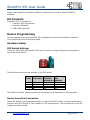
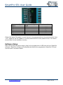
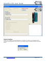
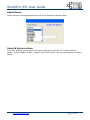
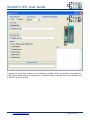
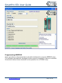
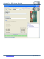
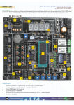
SmartPro S51 User Guide
SmartPro S51 User Guide
www.protosmart.co.uk
Page 1 of 10
SmartPro S51 User Guide
Kit Contents ...............................................................................................................................................3
Device Programming ..............................................................................................................................3
Hardware Setup ...................................................................................................................................3
DIP Switch Settings ........................................................................................................................3
Device Insertion/Connection .......................................................................................................3
Software Setup .....................................................................................................................................4
Select Interface ................................................................................................................................6
Select Device .....................................................................................................................................7
Select & Perform Action ................................................................................................................7
Programming EEPROM ..................................................................................................................9
www.protosmart.co.uk
Page 2 of 10
SmartPro S51 User Guide
Please view SmartPro Installation Guide for instructions on how to install SmartPro
software.
Kit Contents
SmartPro S51 Kit consists of:
• SmartPro S51 Programmer
• SmartPro Software
• USB Cable (optional)
Device Programming
Device programming using SmartPro S51 programmer along with SmartPro software is
very simple and involves following steps.
Hardware Setup
DIP Switch Settings
There is a DIP switch on SmartPro S51 which must be configured properly to program a
device as shown below.
Table below shows the valid settings of the DIP switch.
DIP
Switch
AT89S2051,
AT89S4051
1
2
3
4
OFF
ON
OFF
ON
AT89S51,
AT89S52,
AT89S8253
OFF
OFF
OFF
OFF
AT25XXX
SPI
EEPROM
OFF
OFF
OFF
ON
DIP switch should be configured prior to connecting the programmer to the computer.
Device Insertion/Connection
Insert the device to be programmer either in the provided Zif socket on the programmer or
connect using SIL (Single in Line) Header for ISP programming. The connections for the SIL
header are shown below.
www.protosmart.co.uk
Page 3 of 10
SmartPro S51 User Guide
SIL Header Signal
Name
SDI
SDO
SCK
CS
GND
+5V
Programmer Signal
Type
Input
Output
Output
Output
Power
Power
Device Connections
Connect to MISO
Connect to MOSI
Connect to SCK
Connect to RST
Connect to GND
*See note below
*Note that when SIL header is used, device to be programmed can be powered either from
“+5V” signal on the SIL header or can be powered from its own power source. The device
should have its own oscillator circuitry.
Software Setup
After having done the above steps, plug in the programmer to USB port and run SmartPro
software. SmartPro software will automatically detect the programmer SmartPro S51 and
connect with it as shown below.
www.protosmart.co.uk
Page 4 of 10
SmartPro S51 User Guide
Alternatively, SmartPro software can be executed before even plugging the programmer
into the USB port. The software screen will display the message “SmartPro not found”.
After plugging in the SmartPro S51 programmer, click on “Connect” button to connect to
the programmer as shown below.
www.protosmart.co.uk
Page 5 of 10
SmartPro S51 User Guide
Select Interface
Select Zif or Header interface depending on whether the device to be programmed is
inserted into Programmer’s Zif socket or connected using SIL Header interface as shown
below.
www.protosmart.co.uk
Page 6 of 10
SmartPro S51 User Guide
Select Device
Select device to be programmed from the list of devices as shown below.
Select & Perform Action
From the “Actions” group, select the desired operation and click on “Perform Actions”
button. As an example, “Erase, Program and Verify Device” has been selected in the figure
below.
www.protosmart.co.uk
Page 7 of 10
SmartPro S51 User Guide
Progress for any action is shown on the software window. Also, Log window is available to
view. Figure below shows an example of successful Erase, Program and Verify operation for
AT89S51 using Zif socket.
www.protosmart.co.uk
Page 8 of 10
SmartPro S51 User Guide
Programming EEPROM
Same procedure as described above should be followed to program EEPROM chips.
The software automatically displayed relative options whenever a device is selected.
Screenshot below shows successful write operation to a AT25040 chip.
www.protosmart.co.uk
Page 9 of 10
SmartPro S51 User Guide
www.protosmart.co.uk
Page 10 of 10