1
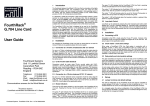
FOM16 TM User’s Manual VER :1.4 FOM16 TM User’s Manual 1. System Description 2. Installation & Operation Manual FOM16 System Description FOM16-V1.4-20040701 Table of content 1 IN TRODU CTION .................................................................................................................................................... 1 2 SYST E M AP PLI CATION ...................................................................................................................................... 3 3 SPECI FI CATIONS AND CHA RA CTERISTI CS ............................................................................................ 4 3.1 MECHANICAL SPECIFICATIONS ................................................................................................................... 4 3.2 INTERFACE CONNECTOR ............................................................................................................................. 4 3.3 INTERFACE SPECIFICATIONS ........................................................................................................................ 4 3.4 ALARM AND INDICATORS ............................................................................................................................ 8 3.5 AUTOMATIC PROTECTION SWITCHING ........................................................................................................ 9 3.6 SYSTEM PERFORMANCE ............................................................................................................................. 9 3.7 LOOP-BACKS ............................................................................................................................................ 10 3.8 POWER SUPPLY ......................................................................................................................................... 11 3.9 PERFORMANCE MONITORING( OPTION) .................................................................................................... 11 3.10 NET MANAGEMENT SYSTEM .................................................................................................................... 12 3.11 OPERATION ENVIRONMENT....................................................................................................................... 13 3.12 RELIABILITY............................................................................................................................................. 13 3.13 EMI.......................................................................................................................................................... 13 -i- FOM16 System Description FOM16-V1.4-200 1 Introduction FOM16™ (universal fiber multiplexer) is a transmission equipment, which can multiplex 4/8/16 2.048Mb/s (E1) tributaries over a single-mode optical fiber for telephone and data services. The system features are E1 G.703 channel interface Redundant fiber 1+1 (Option) protection Link distance up to 50 Km Working temperature up to 60°C for outdoor applications Low Bit Error Rate (BER < 10 - 1 0 ) Software configuration. Desk-top or mountable on standard 19”/23” rack conforming to ETS recommendation 300119 Easy to configure and maintain Access maintenance functions locally and remotely. Performance monitoring and data storage Compatible with Gregorian calendar dates and 2000 A.D. Power supply: AC and/or DC Available synchronization to external clock (option) Linear add/drop and ring topology (option) Network management (option) -1- FOM16 System Description FOM16-V1.4-20040701 4/8/16 × E1 FOM16 FOM16 4/8/16 × E1 Fig.1 FOM16 with 4/8/16 E1 interfaces 4/8/16 E1 Signal Tip Ring Tip Ring E1 Transformer MUX DEMUX CODER DECODER E1 Line Interface Tip Ring Tip Ring Fig.2 FOM16 system block diagram -2- Optical Transceiver FOM16 System Description FOM16-V1.4-200 2 System Application FOM16™ consists of high-speed interface, MUDEM (multiplex / demultiplex), and low-speed interface. The low-speed interface provides electrical interfaces for transmit/receive 4, 8, or 16 E1 signals, and the high-speed interface uses a laser diode (LD) transmitter and a PINFET receiver to provide optical interface. The MUDEM multiplexes / demultiplexes low-speed tributaries into a high-speed signal. FOM16™ is a high-quality, reliable, and robust digital signal transmission equipment which is suitable for inter-office and access network applications. FOM16™ system applications are as follows: Connections between mobiles switch centers and base stations in cellular phone networks. Connections between the COT (Central Office Terminal) and RT (Remote Terminal) of DLC (Digital Loop Carrier) systems. Trunk connections between digital switches. Optical transmission for LAN/WAN applications. Transmission media for ATM networks WAN or LAN LAN FOM16 DLC FOM16 FOM16 FOM16 DLC CO Switch FOM16 FOM16 CO Switch Mobile phone switch CO Switch FOM16 FOM16 Fig.3 System Applications -3- Mobile phone base station FOM16 System Description FOM16-V1.4-20040701 3 Specifications and Characteristics 3.1 Mechanical Specifications Shelf size: 45mm (Height) × 436mm (Width) × 330mm (Depth) Fig.4 FOM16 Front View Fig.5 FOM16 Rear View 3.2 Interface connector E1 interface: DB-25 female connector Optical Interface: FC/PC type (single-mode) Alarm interface: DB-9 female connector Power interface: DC power terminal or AC Plug CID: RS-232 DB-9 male connector NMS: RS-232 DB-9 male connector LAN: RJ-45 female connector 3.3 Interface specifications 3.3.1 System Capacity: Four, eight, or sixteen 2.048Mb/s (E1) 3.3.2 E1 signal interface: (1) Bit Rate: 2.048Mb/s±50ppm. (2) Line code: HDB3. (3) Pulse Shape: ITU-T G.703 shown as Fig. 6 (4) Impedance: 120 Ω ± 5%, symmetrical pair -4- FOM16 System Description FOM16-V1.4-200 (5) Nominal pulse width: 244ns (6) Ratio of the amplitudes of positive and negative pulse at the center of the pulse interval: 0.95 to 1.05 (7) Ratio of the width of positive and negative pulses at the nominal half amplitude: 0.95 to 1.05 (8) The allowable attenuation range of an E1 input signal: 0 ~ 12 dB @1024KHz, i.e. E1 copper (0.65mm) can transmit up to 400 meters. (9) E1 jitter characteristics: G.742 and G.823. (10) Minimum return loss for E1 input: 51 ~ 102KHz Æ 12dB 102 ~ 2048KHz Æ 18dB 2048 ~ 3072KHz Æ 14dB (11) The 2.048Mbps input/output interface offers compensation circuit. (12) Provision to input/output port with connection to the earth at the outer connector of the screen 269 ns (244+25) 20% 10% 100% Normal Pulse 10% 20% 194 ns (244-50) 50% 244 ns 0% 219 ns (244-25) 10% 10% 10% 20% 488 ns (244+244) Fig. 6 Mask of the pulse at the E1 interface 3.3.3 E1 jitter requirements: ITU-T G.823 & G.742 (1) Jitter generation -5- 10% FOM16 System Description FOM16-V1.4-20040701 The jitter of the E1 output signal in the absence of input jitter shall not exceed the following limits in both bands simultaneously. The characteristics weighting functions of Band 1 and Band 2 are shown as Fig. 7. Band 1: 0.25 unit intervals peak-to-peak. Band 2: 0.05 unit intervals peak-to-peak with a probability of 99.9% during a measurement period of 10 seconds. (2) Jitter tolerance The E1 signal interface should accommodate input jitter of a least magnitude shown as Fig.8. (3) Jitter transfer For E1 interface, the result of jitter transfer performance should be under the curve shown as Fig. 9. Weighting (dB) 0 Slop: 29dB/Decade 20Hz 18KHz Band 1 Band 2 100 kHz 100 kHz Frequency (Log Scale) Fig.7 Frequency characteristic weighting functions -6- FOM16 System Description FOM16-V1.4-200 Signal Input Jitter Amplitude (PK to PK U.I.) A1 Acceptable Range A2 F1 F2 F3 F4 Jitter Frequency Digital Rate ( kbit/s) Peak-to-peak amplitude unit interval A1 E1 1.5 A2 0.2 Pseudo-rand Frequency (Hz) om test-signal F1 F2 F3 F4 20 2.4k 18k 100k Fig.8 Input jitter tolerance at E1 interface 0.5dB 20dB/Decade Acceptable Range -19.5dB 10Hz 40Hz Fig.9 E1 Jitter Transfer Performance -7- 400Hz ITU-T Q.151 2.15-1 FOM16 System Description FOM16-V1.4-20040701 3.3.4 Optical signal interface: ITU-T G.981 Optical source: MLM-1310 nm type LD Optical wavelength range: 1260 nm to 1360 nm Optical connector: FC/PC type Line coding format: Scrambled NRZ Short -haul Output power: -7 ~ -15 dBm @ 1310 nm Minimum receive sensitivity: -34 dBm @ 10 -10 BER System Gain: > 19 dB (at 1×10⁻¹⁰ BER) Long -haul Output power: 0 ~ -5 dBm @ 1310 nm Minimum receive sensitivity: -36 dBm @ 10 -10 BER System Gain: > 30 dB (at 1×10⁻¹⁰ BER) Protection type: 1+1 automatic switching 3.4 Alarm and indicators 3.4.1 The system monitors all alarms, such as loss of signals, optical signal loss remote alarm, etc. in real time. The system also provide the following four alarm relay contacts: MJA: Audible Major Alarm MJV: Visible Major Alarm MNA: Audible Minor Alarm MNV: Visible Minor Alarm 3.4.2 Shown as Table 1 ~ Table 3, FOM16 activates the LEDs and LCM on the front panel when system or signal failures are detected. 3.4.3 Shown as Table 1 ~ Table 3, FOM16 also active LEDs and LCM on the front panel when alarm and status indications for local and remote monitoring happen. Channel LED ( 1~16 ) E1 Channel( 1~16 ) LED Action E1 out of service Off E1 in service without LOS Green On E1 in service with LOS Red On E1 in service with LLB or RLB Green Blinking Table 1 LEDs about E1 Channel Operations -8- FOM16 System Description FOM16-V1.4-200 Channel LED Optical Channel (Working or Protection) LED Action Out of service Off Channel in service without LOS Green On Channel in service with LOS Red On Channel in standby status without LOS Yellow On Channel in standby status with LOS Red On Channel in service with LLB or RLB Green Blinking Table 2 LEDs about Fiber Optical Operations System LED LED Action System Status System Power On PWR LED Green On Alarm Cut Off ACO LED Green On RLB or LLB ABN LED Green On Optical Working and Protection channels are in service with LOS or LOF MJ LED Red On Either of Optical Working and Protection channels are in service with LOS or LOF MN LED Yellow On Any E1 channel is in service with LOS MJ LED Red On Alarms happen in Near End NE LED Yellow On Alarms happen in Far End FE LED Yellow On Table 3 LEDs about System Operations 3.5 Automatic protection switching The system can offer optical 1+1 automatic protection switching when optical signal fails. The mechanism of protection switching prevents unwanted oscillation between service and protection facilities and the switching time is less than 60 ms. 3.6 System Performance FOM16 provides high transmission performance (less than 1 error per 1010 bits) for each E1 digital signal through the system. (ITU-T G.826) -9- FOM16 System Description FOM16-V1.4-20040701 3.7 Loopbacks Shown as Fig.10a ~ Fig.10d, FOM16 provides local and remote loopback tests by CID or via LCM and push bottoms. These functions are used to test the integrity and connectivity of E1 and optical signals. E1 Input AIS AIS E1 Output E1 Output E1 Input Near End FOM16 Far End FOM16 Fig.10a E1 Local Loopback E1 Input AIS E1 Output E1 Output E1 Input Near End FOM16 Far End FOM16 Fig.10b E1 Remote Loopback E1 Input E1 Output AIS E1 Output E1 Input Far End FOM16 Near End FOM16 Fig.10c Optical Local Loopback -10- FOM16 System Description FOM16-V1.4-200 E1 Input AIS E1 Output E1 Output E1 Input Near End FOM16 Far End FOM16 Fig.10d Optical Remote Loopback 3.8 Power supply 3.8.1 Input power DC: –36 V to –72 V, AC ripple up to 0.5 Vp-p AC: 220V ± 10%, 50 Hz ± 10% 3.8.2 Power consumption: < 30 Watt 3.9 Performance Monitoring( option) 3.9.1 FOM16 provides the performance monitoring parameters as follows (1) Near-End Line Code Violation (CV) Errored Second (ES) (2) Near-End Path Code Violation (CV) Errored Second (ES) Severely Errored Second (SES) Unavailable Second (UAS) (3) Far-End Line Code Violation (CV) Errored Second (ES) (4) Far-End Path Code Violation (CV) Errored Second (ES) -11- FOM16 System Description FOM16-V1.4-20040701 Severely Errored Second (SES) Unavailable Second (UAS) 3.9.2 Parameter Descriptions (1) CV: HDB3 line coding violation or path coding violation. (2) ES: An ES is a second during which at least one CV occurred. (3) SES: A SES is a second with X or more CV. Candidate different values of X to correspond to BER thresholds respectively. The values for X are specified in Table 4. The number of CVs within a second constitutes a SES can be configured. (4) UAS: UAS is a count of one-second intervals for which the line or path is unavailable. The line or path is said to become unavailable at the onset of 10 consecutive SESs. BER 1×10⁻³ 1×10⁻⁵ 1×10⁻⁶ 1.5×10⁻⁷ Optical X=68736 X=687 X=68 X=10 E1Channel X=2048 X=2 N/A N/A Channel Table 4 X values about BER 3.9.3 Threshold Setting Threshold values of registers, current 15 minutes, current hour and current day, for E1 parameters CV, ES, SES, and UAS are settable. A threshold alarm is generated when threshold violation occurs. 3.9.4 Performance Data Storage FOM16 provides a sufficient size of internal memory to store the current and historical performance data. The historical performance data includes 15-minuts interval ES, SES, and UAS of the latest 24 hours as well as total 24-hour interval ES. SES, and UAS of the latest 7 days that derives from the errored messages on incoming and outgoing digital paths. 3.10 Network Management System 3.10.1 FOM16 reports the alarm automatically to a CID and controller of RS-232 (V.24) interface. Operation, administration, maintenance, and provision (OAM & P), including querying and monitoring and loopbacks, can also be accessible through RS-232 interface locally and/or remotely. 3.10.2 Network management protocol provides SNMP. About the Management Information Base (MIB) version and contents of SNMP agent, please refer FOM16 Monitoring Software Operation Description. 3.10.3 FOM16 can identify the time of various errors or events, which happened to the E1 -12- FOM16 System Description FOM16-V1.4-200 facilities, and the far-end performance message and management, are submitted through the DCC overhead channel of FOM16. 3.11 Operation environment Ambient temperature: 0°C to 60°C Relatively humidity: 5% to 95% (Non-condensing) 3.12 Reliability MTBF (Mean Time between Failure): 47,000 hours MTTR (Mean Time to Repair): 5 hours 3.13 EMI The FOM16 complies with the specifications of the Class A of CISPR 22 and the Class A of subpart B of Part 15 of the FCC Rule of U.S.A. -13- FOM16 System Description FOM16-V1.4-20040701 -14-