1
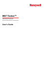
MX7 Tecton™
Hand-Held Computer
Microsoft® Windows® Mobile 6.5 Operating System
User's Guide
Disclaimer
Honeywell International Inc. (“HII”) reserves the right to make changes in specifications and other information contained in this
document without prior notice, and the reader should in all cases consult HII to determine whether any such changes have
been made. The information in this publication does not represent a commitment on the part of HII.
HII shall not be liable for technical or editorial errors or omissions contained herein; nor for incidental or consequential damages
resulting from the furnishing, performance, or use of this material.
This document contains proprietary information that is protected by copyright. All rights are reserved. No part of this document
may be photocopied, reproduced, or translated into another language without the prior written consent of HII.
© 2011-2012 Honeywell International Inc. All rights reserved.
Web Address: www.honeywellaidc.com
RFTerm is a trademark or registered trademark of EMS Technologies, Inc. in the United States and/or other countries.
Microsoft® Windows, ActiveSync®, MSN, Outlook®, Windows Mobile®, the Windows logo, and Windows Media are
registered trademarks or trademarks of Microsoft Corporation.
Marvell® is a registered trademark of Marvell Technology Group Ltd., or its subsidiaries in the United States and other
countries.
Summit Data Communications, Inc. Summit Data Communications, the Summit logo, and “The Pinnacle of Performance” are
trademarks of Summit Data Communications, Inc.
The Bluetooth® word mark and logos are owned by the Bluetooth SIG, Inc.
Symbol® is a registered trademark of Symbol Technologies. MOTOROLA, MOTO, MOTOROLA SOLUTIONS and the
Stylized M Logo are trademarks or registered trademarks of Motorola Trademark Holdings, LLC and are used under license.
Hand Held is a trademark of Hand Held Products, Inc., a subsidiary of Honeywell International.
Wavelink®, the Wavelink logo and tagline, Wavelink Studio™, Avalanche Management Console™, Mobile Manager™, and
Mobile Manager Enterprise™ are trademarks of Wavelink Corporation, Kirkland.
RAM® and RAM Mount™ are both trademarks of National Products Inc., 1205 S. Orr Street, Seattle, WA 98108.
Acrobat® Reader © 2012 with express permission from Adobe Systems Incorporated.
Other product names or marks mentioned in this document may be trademarks or registered trademarks of other companies
and are the property of their respective owners.
Patents
For patent information, please refer to www.honeywellaidc.com/patents.
Limited Warranty
Refer to www.honeywellaidc.com/warranty_information for your product’s warranty information.
Table of Contents
Chapter 1: Introduction
1-1
About this Guide
1-1
Laser Warnings and Labels
1-2
Label Location
1-2
Label
1-2
Components
1-3
Front
1-3
Back
1-4
I/O Port and Cables
1-5
Scanner / Imager Aperture
1-7
Handle
1-7
Handstrap
1-7
Keypads
1-8
55 Key Delete Primary ANSI Keypad
1-8
55 Key Backspace Primary ANSI Keypad
1-8
32 Key Numeric-Alpha Keypad
1-9
Chapter 2: Set Up A New MX7 Tecton
2-1
Hardware Setup
2-1
Software Setup
2-1
Device Unlocked / Device Locked
2-2
Battery
2-3
Connect or Remove the Battery Pack
2-3
Insert/Replace Battery
2-3
Remove Battery
2-4
Hotswap the Main Battery
2-4
Charge or Recharge the Main Battery
2-5
Backlights and Indicators
2-6
Status LEDs
2-6
System Status LED
2-6
Alpha mode Status LED
2-6
Scan Status
2-6
Toggle Vibrate Indicator
2-7
Tapping the Touchscreen with a Stylus
2-8
Touchscreen
2-9
Calibrating the Touchscreen
2-9
Adjusting the Display Backlight Timer
2-9
Apply the Touchscreen Protective Film
2-9
Using the Input Panel / Virtual Keyboard
2-10
i
Set Time Zone
2-11
Set Power Timers
2-12
Adjust Sounds and Notifications
2-13
Setup Terminal Emulation Parameters
2-14
Using the AppLock Switchpad
2-15
Using the Keypad
2-15
Using the Touchscreen
2-15
Connecting Bluetooth Devices
Taskbar Connection Indicator
Reboot Sequences
2-16
2-17
Suspend / Resume
2-17
Warmboot
2-17
Cold Boot / Restart
2-17
Attaching the Handstrap
2-18
Attaching the Trigger Handle
2-19
Adjust Headset / Microphone and Secure Cable
2-20
Connecting the Headset Cable
2-21
Cleaning the Touchscreen and Scanner Aperture
2-22
Startup Help
2-23
Continuous Scan Mode
Chapter 3: Connecting Cables to the MX7 Tecton
2-23
3-1
Connecting the USB Client and Power Cable
3-1
Connecting the Serial and Power Cable
3-2
Connecting an External Power Supply
3-3
Connecting Vehicle Power
3-4
DC to DC Power Supply Installation
3-4
Connecting Electrical Cables to Power Sources
3-4
Wiring Schematic
3-5
Connect Vehicle Electrical Connection
3-5
Vehicle 12V Bare Wire Adapter
3-7
Vehicle Cable Connection Cable (Fuse Not Shown)
3-7
Connecting the Power Cable to the Vehicle
3-8
Connect Vehicle 12 VDC Connection
3-9
Connect Power Supply to Vehicle Cradle
3-10
Cradle Power Connector Port
Chapter 4: Product Agency Compliance - MX7 Tecton
Laser Light Safety Statement
Chapter 5: Technical Assistance
ii
2-16
3-10
4-1
4-3
5-1
Chapter 1: Introduction
The MX7 Tecton™ with Microsoft Windows®Mobile 6.5 operating system is a rugged, portable, hand-held mobile computer
capable of wireless data communications. The MX7 Tecton can transmit information using an 802.11 network card and it can
store information for later transmission through an RS-232 or USB port. The MX7CS (Cold Storage) device functions normally
in various temperature ranges.
The MX7 Tecton is vertically oriented and features backlighting for the display. Keypads are available in 55-key alphanumeric
and 32-key numeric-alpha versions.
This device can be scaled from a limited function batch computer to an integrated wireless scanning computer. A trigger handle
is available as an accessory.
The stylus attached to the handstrap is used to assist in entering data and configuration. Protective film for the touchscreen is
available as an accessory.
The MX7 Tecton is powered by a 2200mAh Lithium-Ion main battery pack and an internal Super-capacitor (Super-cap) battery.
About this Guide
This MX7 Tecton User's Guide provides instruction for the end-user or system administrator to follow when setting up a new
MX7 Tecton.
This user's guide has been developed for a MX7 Tecton with a Microsoft® Windows® Mobile® 6.5 operating system.
1-1
Laser Warnings and Labels
l
Do not look into the laser’s lens.
l
Do not stare directly into the laser beam.
l
Do not remove the laser caution labels from the MX7 Tecton.
l
Do not connect the laser bar code aperture to any other device. The laser bar code aperture is certified for use with the
MX7 Tecton only.
Caution
Laser radiation when open. Please read the caution labels. Use of controls, adjustments or performance of
procedures other than those specified herein may result in hazardous radiation exposure.
Label Location
Label
1-2
Components
Front
1. Scanner/Imager Aperture
6. Blue Key (Sticky Key)
2. Speaker
7. Scan Status LED
3. System Status LED
8. Cable Port
4. Scan Button
9. On / Off Button
5. Orange Key (Sticky Key)
10. Alpha Lock LED (32-Key only)
Diamond Keys
1-3
Back
1. Scanner/Imager Aperture
2. Stylus and Stylus Pocket
3. Trigger Handle Attach Points
4. Main Battery
5. Battery Fastener
6. Cable Port
1-4
I/O Port and Cables
Cable: Multipurpose RS-232 and Power
MX7055CABLE
Cable: Multipurpose USB and Power
MX7052CABLE
Adapter/Cable : Audio
MX7060CABLE
1-5
Adapter: RS-232 PC port to D9 male
MX7058CABLE
1-6
Scanner / Imager Aperture
1. Scanner / Imager Aperture
2. MX7 Tecton Front
Caution: Never stare directly into the beam aperture.
If Continuous Scan Mode has been enabled (default is disabled), the laser is always on and decoding. Caution: Laser beam
is emitted continuously. Do not stare into the laser beam.
Handle
1. Imager / Scanner
Aperture
2. Trigger
3. Handle
4. Tether Attach Point
Handstrap
1. Handstrap
2. Handstrap Retainer Bracket and mounting screws
3. Handstrap Clip
1-7
Keypads
55 Key Delete Primary ANSI Keypad
1. System Status LED
2. Volume Control Icon
3. Display Brightness Icon
4. Diamond Key
5. Scan Button
6. Enter Key
7. Orange Key (Sticky Key)
8. Blue Key (Sticky Key)
9. On Off Button
10. Scan Status LED
Spc and Del key location
55 Key Backspace Primary ANSI Keypad
1. System Status LED
2. Volume Control Icon
3. Display Brightness Icon
4. Diamond Key
5. Scan Button
6. Enter Key
7. Orange Key (Sticky Key)
8. Blue Key (Sticky Key)
9. On Off Button
10. Scan Status LED
Spc and Bksp key location
1-8
32 Key Numeric-Alpha Keypad
1. System Status LED
2. Alpha Status LED
3. Diamond Keys
4. Scan Button
5. Enter Key
6. Alph Key
7. Orange Key (Sticky Key)
8. Blue Key (Sticky Key)
9. On Off Button
10. Scan Status LED
1-9
1-10
Chapter 2: Set Up A New MX7 Tecton
This page lists a quick outline of the steps you might take when setting up a new MX7 Tecton. More instruction for each step is
listed later in this guide. Please refer to the MX7 Tecton for Windows Mobile Reference Guide for additional information and
instruction.
Contact your representative if you need additional help.
Note:
Installing or removing accessories should be performed on a clean, well-lit surface. When necessary,
protect the work surface, the MX7 Tecton, and components from electrostatic discharge.
This user's guide has been developed for a MX7 Tecton with a Microsoft® Windows® Mobile® 6.5 operating system.
Hardware Setup
1. Connect accessories.
2. Connect cables.
3. Insert/connect a fully charged battery
4. If the screen does not automatically display, press the Power key.
Software Setup
Hardware setup should be completed before software setup begins.
1. If prompted, calibrate Touch screen
2. Set Date and Time Zone
3. Set Power Timers
4. Set Speaker Volume
5. Pair Bluetooth devices
6. Set Wireless client parameters
7. Set terminal emulation parameters
8. Reboot to save changed settings
9. Set the AppLock parameters
10. Set the DCWedge parameters
Please refer to the MX7 Tecton for Windows Mobile Reference Guide for additional information and instruction.
Note:
Low Power Scanner does not support aim mode. Any attempt to adjust the aiming beam using SE955
programming bar codes in the Integrated Scanner Programming Guide will fail. The Low Power
scanner does not decode Codablock, Code93i, Matrix 2 of 5 or Telepen symbologies.
2-1
Device Unlocked / Device Locked
The MX7 Tecton can be locked manually by tapping Device unlocked on the Today screen. By default, this option is included
on the Today screen. Care should be taken to not accidentally tap this area of the Today screen. Lock can be removed from the
Today screen by selecting the Start | Settings | Personal | Today | Items tab.
The MX7 Tecton can also be configured to Lock automatically after a defined period of inactivity.
This setting is accessed via Start | Settings | Lock | Password tab. By default, this option is Disabled.
When the MX7 Tecton is locked, the Today screen displays Device locked by default. Click Unlock at the lower part of the
screen:
2-2
l
If there is no password or PIN set, click Unlock on the next screen to unlock the MX7 Tecton. The MX7 Tecton is
returned to normal operation.
l
If there is a password or PIN set, enter the password/PIN and click Unlock. If several unsuccessful attempts are made,
the MX7 Tecton can be configured to display a password hint.
Battery
Connect or Remove the Battery Pack
The MX7 Tecton will not function unless the battery pack is in place and securely latched.
Be sure to place the unit in Suspend Mode before removing the battery. Failing to properly place the device in Suspend mode
will result in a loss of all unsaved data.
An MX7 Tecton will retain data, while the main battery is removed and replaced with a fully charged main battery, for 5 minutes.
Important: When the internal battery power is Low or Very Low connect the AC adapter to the MX7 Tecton before replacing the
main battery.
Note:
The battery should not be replaced in a dirty, harsh or hazardous environment. When the battery is
not connected to the MX7 Tecton, any dust or moisture that enters the battery well or connector may
transfer to the battery/well terminals, potentially causing damage.
Warning : Only use Honeywell MX7A380BATT / MX7392BATT or a Low Temperature (CS) Battery : MX7A381BATT /
MX7393BATT (Blue label) batteries as replacements.
Insert/Replace Battery
To insert the main battery, complete the following steps:
1. Detach the bottom hook of the handstrap (if installed).
2. Tilt the end (without the latch) of the fully charged battery pack into the upper end of the battery compartment, and firmly
press the other end until it is fully inserted into the battery compartment
3. Push down on the battery until the retaining clip clicks into place.
4. Replace the handstrap clip in its holder (if installed).
The MX7 Tecton draws power from the battery immediately upon successful connection.
Check battery status by tapping the battery icon at the top right of the Today screen or tap Start | Settings | System | Power
| Battery. Main battery level, internal battery level, status and other details are displayed.
2-3
Remove Battery
To remove the battery, complete the following steps:
1. Place the MX7 Tecton in Suspend mode.
2. Detach the bottom hook of the handstrap (if installed).
3. Slide the battery retaining clip down to release the main battery.
4. Pull the battery up and out of the battery well.
Place the discharged battery pack in a powered battery charger.
Hotswap the Main Battery
Place the MX7 Tecton in Suspend Mode. Honeywell recommends any work in progress be saved prior to replacing the battery
pack.
Simply replace the discharged battery with a fully-charged battery. An MX7 Tecton, with a fully charged internal battery, will
retain data during a battery hotswap for 5 minutes.
2-4
Charge or Recharge the Main Battery
Warning : Only use Honeywell MX7A380BATT / MX7392BATT or a Low Temperature (CS) Battery : MX7A381BATT /
MX7393BATT (Blue label) batteries as replacements.
Note:
The MX7 Tecton Battery Charger is designed for an indoor, protected environment.
New batteries must be fully charged prior to use.
The main battery can be recharged in an AC powered Battery Charger after the battery has been removed from the MX7 Tecton
or its packing material when new.
The main battery while in the MX7 Tecton can be recharged using several different methods.
Note:
An external power source is required before the main battery in the MX7 Tecton will recharge.
The main battery can be recharged while it is in the MX7 Tecton:
l
by connecting the MX7 Tecton AC power adapter to the I/O connector at the base of the MX7 Tecton.
l
by docking the MX7 Tecton in a powered desk cradle
l
by docking the MX7 Tecton in a powered vehicle cradle
l
or by connecting the car power adapter (CLA) to the I/O connector at the base of the MX7 Tecton.
Note:
An uninterrupted external power source (wall AC adapters) transfers power to the computer’s internal
charging circuitry which, in turn, recharges the main battery and internal battery. Frequent connection
to an external power source, if feasible, is recommended to maintain internal battery charge status as
the internal battery cannot be recharged by a dead or missing main battery.
2-5
Backlights and Indicators
Status LEDs
The MX7 Tecton System Status LED is located at the top left of the keypad, below the F3 key. The Alpha Mode LED is located
below the F4 key on the 32-key keypad.
LEDs (Light Emitting Diodes) are located on the front of the MX7 Tecton. They are:
1. System Status LED indicates power management status.
2. Alpha Mode Status LED applies to the 32-key keypad only.
System Status LED
Blinking Red
Battery power fail; critical suspend mode
Steady Red
Main battery low
Blinking Green
Display turned off
Yellow / Amber
A few seconds when Power key is pressed
No Color
No user intervention required.
Alpha mode Status LED
Steady Green
Device is in “Alpha” character input mode
No Color
Device is in “Numeric” key input mode
Scan Status
An oval indicator situated below the keypad and next to the On button.
Steady Green
Good scan
Steady Amber
Decoder engine storing changed parameters
Steady Red
Scan in progress
No Color
Scanner / Imager ready for use or no scanner installed.
2-6
Toggle Vibrate Indicator
The MX7 Tecton vibration motor is activated when a scan is completed successfully (good scan vibration) or with a failure
(scan key released before good scan, timeout, or rejected because of Data Options configuration).
The vibrations can be detected under the handstrap or through the trigger handle.
Use the Speaker Volume / Vibrate Icon in the top right corner of the Today screen to toggle sound and/or vibration on or off.
Vibration can also be set using Start | Settings | System | Data Collection | Notification tab. Since the Data Collection Wedge
uses the operating system interface to sound beeps, if the volume/vibrate icon is set to anything other than On, Wedge beeps
do not sound. Wedge vibration is not affected by these settings.
2-7
Tapping the Touchscreen with a Stylus
Note:
Always use the point of the stylus for tapping or making strokes on the touch screen.
Never use an actual pen, pencil, or sharp/abrasive object to write on the touch screen.
Hold the stylus as if it were a pen or pencil. Touch an element on the screen with the tip of the stylus then remove the stylus
from the screen.
Firmly press the stylus into the stylus holder when the stylus is not in use.
Using a stylus is similar to moving the mouse pointer then left-clicking icons on a desktop computer screen.
Using the stylus to tap icons on the touch screen is the basic action that can:
l
Open applications
l
Choose menu commands
l
Select options in dialog boxes or drop-down boxes
l
Drag the slider in a scroll bar
l
Select text by dragging the stylus across the text
l
Place the cursor in a text box prior to typing in data
l
Place the cursor in a text box prior to retrieving data using a scanner/imager or an input/output device connected to a
serial port.
A stylus replacement kit is available.
2-8
Touchscreen
Calibrating the Touchscreen
If the touchscreen is not responding properly to stylus taps, you may need to recalibrate the touchscreen.
Recalibration involves tapping the center of a target. If you miss the center, keep the stylus on the screen, slide it over the
target's center, and then lift the stylus.
To recalibrate the screen, select Start | Settings | System | Screen | General tab.
To begin, tap the Align Screen button on the screen with the stylus.
Follow the instructions on the screen. Tap the OK button when complete, if necessary.
Adjusting the Display Backlight Timer
Start | Settings | System | Backlight
The backlight settings use the Honeywell set of default timeouts.
When the backlight timer expires, the display backlight and the keypad backlight turn off.
Default values are 30 seconds for Battery, 1 minute for External and both the check boxes are enabled.
Apply the Touchscreen Protective Film
First, clean the touchscreen of fingerprints, lint particles, dust and smudges.
Remove the protective film from its container. Remove any protective backing from the film sheet by lifting the backing from a
corner of the film. Discard the backing.
Apply the film to the touchscreen starting at one side and smoothing it across the display. If air bubbles appear, raise the film
slightly and continue smoothing the film across the display until it covers the glass surface of the display. If dust, lint or
smudges are trapped between the protective film and the glass display, remove the protective film, clean the display and apply
the protective film again.
Contact your representative about protective film packs designed specifically for your MX7 Tecton touchscreen.
2-9
Using the Input Panel / Virtual Keyboard
The virtual keyboard is always available when needed e.g. text entry.
Place the cursor in the text entry field and, using the stylus:
l
Tap the Shift key to type one capital letter.
l
Tap the CAPS key to type all capital letters.
l
Tap the áü key to access symbols.
Some applications do not automatically display the Input Panel. In this case, do the following to use the Input Panel:
l
Tap the keyboard icon in the taskbar. Tapping the keyboard icon in the taskbar is a toggle action (On / Off).
l
Move the cursor into the text entry field when you want to enter data using the Input Panel.
When finished entering data, tap the icon in the Taskbar again.
2-10
Set Time Zone
Note:
The first time it is powered up, or the device returns from a Clean Boot, the MX7 Tecton may reset
the Time to the factory default value.
To set the Time Zone, tap the Date/Time on the Today screen or tap Start | Settings | Clock and Alarms icon.
Select the physical time zone. If required, adjust the time and calendar date and tap ok.
2-11
Set Power Timers
Tap Start | Settings | Power | Advanced tab. Adjust the timer values and tap OK. When the timer expires, the MX7 Tecton
enters Suspend Mode.
2-12
Adjust Sounds and Notifications
Note:
An application may override the control of the speaker volume. Turning off sounds saves power and
prolongs battery life.
The speaker is located on the front of the device above the MX7 Tecton logo. The audio volume can be adjusted to a
comfortable level for the listener. Operational tones are emitted from the speaker.
Sounds for Events and Programs are enabled by default. Notifications are disabled by default.
Tap the speaker icon in the top right corner. Move the slider up and down to adjust the sound. Vibrate can be toggled on and off.
2-13
Setup Terminal Emulation Parameters
Before you make a host connection, you will, at a minimum, need to know:
l
the alias name or IP address (Host Address) and
l
the port number (Telnet Port) of the host system to properly set up your host session.
1. Make sure the mobile client network settings are configured and functional. If you are connecting over wireless LAN
(802.11x), make sure your mobile client is communicating with the Access Point.
2. From Start | Program, run RFTerm or tap the RFTerm icon on the desktop.
3. Select Session | Configure from the application menu and select the "host type" that you require. This will depend on
the type of host system that you are going to connect to; i.e. 3270 mainframe, AS/400 5250 server or VT host.
4. Enter the "Host Address" of the host system that you wish to connect to. This may either be a DNS name or an IP
address of the host system.
5. Update the telnet port number, if your host application is configured to listen on a specific port. If not, just use the
default telnet port.
6. Select OK.
7. Select Session | Connect from the application menu or tap the "Connect" button on the Tool Bar. Upon a successful
connection, you should see the host application screen displayed.
To change options such as Display, Colors, Cursor, Bar Code, etc., please refer to these sections in the RFTerm Reference
Guide for complete descriptions of these and other features.
2-14
Using the AppLock Switchpad
Switchpad Icon in Taskbar
Click the switchpad icon in the taskbar.
A checkmark on the switchpad menu indicates applications currently active or available for Launching by the MX7 Tecton user.
When Keyboard, on the Switchpad Menu, is selected, the default input method (Input Panel, Transcriber, or custom input
method) is activated.
Using the Keypad
One switch key sequence (or hotkey) is defined by the Administrator for the end-user to use when switching between locked
applications. This is known as the Activation key.
When the switch key sequence is pressed on the keypad, the next application in the AppLock configuration is moved to the
foreground and the previous application moves to the background. The previous application continues to run in the background.
MX7 Tecton key presses affect the application in focus only.
Using the Touchscreen
The figure shown above is an example and is shown only to aid in describing how the user can switch between applications
using a stylus.
When the user taps the Switchpad icon with the stylus, a menu pops up listing the applications available to the user. The user
can tap an application name in the popup menu and the selected application is brought to the foreground. The previous
application continues to run in the background. Stylus taps affect the application in focus only. When the user needs to use the
Input Panel, they tap the Keyboard option. Input Panel taps affect the application in focus only.
2-15
Connecting Bluetooth Devices
Before connecting to Bluetooth Devices:
l
The system administrator has discovered, paired, connected and disconnected (using LXEZ Pairing ) Bluetooth devices
for each MX7 Tecton.
l
The system administrator has enabled and disabled LXEZ Pairing parameters for the MX7 Tecton.
l
The system administrator has also assigned a Computer Friendly Name using LXEZ Pairing for the MX7 Tecton.
To connect Bluetooth devices, the MX7 Tecton should be as close as possible and in direct line of sight (distances up to 32.8
feet or 10 meters) with the targeted Bluetooth device during the discovery and pairing process.
If the devices are in Suspend, tap the power key to wake the MX7 Tecton.
Using the correct procedure, wake the targeted Bluetooth device if necessary.
There may be audible or visual signals as both devices discover and pair with each other.
Taskbar Connection Indicator
MX7 Tecton is connected to one or more of the targeted Bluetooth device(s).
MX7 Tecton is not connected to any Bluetooth device.
MX7 Tecton is ready to connect with any Bluetooth device.
MX7 Tecton is out of range of all paired Bluetooth device(s). Connection is inactive.
There may be audible or visual signals from paired devices as they move back into range and re-connect with the Bluetooth
hardware in the MX7 Tecton.
2-16
Reboot Sequences
When the Windows Mobile Today panel is displayed or an application begins, the power up sequence is complete. If you have
previously saved your settings, they will be restored on reboot. Application panel changes are saved when ok is tapped on an
application properties panel.
During the processes that follow there may be small delays while the wireless client connects to the network and Bluetooth
relationships establish or re-establish.
Suspend / Resume
Quickly tapping the Power key places the MX7 Tecton in Suspend mode. Quickly tapping the Power key again, pressing any
key, pressing the trigger (on the trigger handle), or tapping the touchscreen, returns the MX7 Tecton from Suspend. The
System LED blinks green when the video display is Off.
or
Hold down the Power key and then the Enter key until the screen blanks. Release the keys and the MX7 Tecton resumes.
Warmboot
Select Start > Settings > System > Registry and click Warmboot. The unit reboots and all programs are re-launched. When the
Today panel is displayed or an application begins, the warm boot sequence is complete.
Cold Boot / Restart
Temporary data not saved is lost. All programs are re-launched, programs installed from CAB files are reinstalled. Previously
saved user settings are restored. Restart may also be called cold boot. Hold down the Blue key, the Scan key and the Power
key until the screen blanks. Release the keys and the MX7 Tecton cold boots.
Be sure to press the Scan key not the Enter key. Pressing the Enter key begins a suspend/resume function instead of a cold
boot function.
2-17
Attaching the Handstrap
Note:
Either the trigger handle is attached to the MX7 Tecton or the handstrap is attached, not both. In the
absence of a trigger handle, the handstrap should be used at all times. The handstrap is pre-installed
on a MX7 Tecton that is purchased without a trigger handle.
1. Handstrap Retainer Bracket
2. Handstrap and tethered stylus
3. Handstrap Clip
Tool Required: Phillips #1 screwdriver (not supplied)
1. Place the MX7 Tecton with the screen facing down, on a flat stable surface.
2. Attach the handstrap retainer bracket to the MX7 Tecton with the screws and washers provided.
3. Slip the Handstrap Clip into the bracket at the base of the MX7 Tecton.
4. Making sure the closed loop fastener surfaces on the handstrap are facing up, slide the strap through the pin in the
bottom bracket and the clip.
5. Fold each end of the strap over so that the closed loop fastener surfaces mate evenly.
6. Test the strap's connection making sure the MX7 Tecton is securely connected to each end of the handstrap's
connectors.
Check the closed loop fastener, retainer bracket and clip connections frequently. If they have loosened, they must be tightened
or replaced before the MX7 Tecton is placed into service again.
2-18
Attaching the Trigger Handle
Pressing the trigger on the trigger handle activates the integrated scanner and functions the same as the Scan key on the
keypad. With the handle installed the Scan key on the keypad remains active. The trigger duplicates the operation.
l
The handle is built of a durable, flexible plastic.
l
The handle will not detach from the MX7 Tecton if the unit is dropped.
l
The trigger handle is a mechanical device. Battery or external A/C power is not
required for operation.
l
The trigger handle does not need to be removed when replacing the main battery
pack.
l
The trigger handle might also be called a pistol grip.
Equipment needed: Torque wrench capable of torquing to 3±1 in/lb (.34±.11 N/m).
Either the trigger handle or the handstrap is attached, not both. Honeywell recommends that, in the absence of a trigger handle,
the handstrap be used at all times.
1. Place the MX7 Tecton with the screen facing down, on a flat stable surface.
2. Remove the handstrap, if installed.
3. Remove the battery.
4. Slide the locking tab on the underside of the trigger handle into the slot at the back of the battery compartment and press
it firmly into place.
5. Ensure that the battery can be inserted into the battery compartment before securing the trigger handle in place.
6. Attach the trigger handle to the MX7 Tecton (as shown above) with the screws provided.
7. Torque the pan head screws to 3±1 in/lb (.34±.11 N/m).
8. Secure the strap tether to the trigger handle.
9. Place the stylus in the stylus holder in the trigger handle.
Periodically check the trigger handle for wear and the connection for tightness. If the handle gets worn or damaged, it must be
replaced. If the trigger handle connection loosens, it must be tightened or replaced before the MX7 Tecton is placed in service.
2-19
Adjust Headset / Microphone and Secure Cable
The headset consists of an earpiece, a microphone, a clothing clip and a cable. The headset attaches to the audio cable end of
the voice cable which attaches to the MX7 Tecton.
Align the audio connector and the headset quick connect cable end. Firmly push the cable ends together until they click and
lock in place.
Do not twist the microphone boom when adjusting the microphone. The microphone should be adjusted to be about two finger
widths from your mouth.
Make sure the microphone is pointed at your mouth. Note the small “Talk” label near the mouthpiece. Make sure the Talk label
is in front of your mouth. The microphone cable can be routed over or under clothing.
Under Clothing
l
Leave the cable exposed only at the top of the collar.
l
Be sure to leave a small loop of cable to allow movement of your head.
Over Clothing
l
Use clothing clips to hold the cable close to your body.
l
Tuck the cable under the belt, but leave a small loop where it goes under the belt.
l
Do not wear the cable on the front of your body. It may get in your way or get caught on protruding objects.
2-20
Connecting the Headset Cable
Headset
1. Microphone
2. Headphones
3. Connects to voice cable end of voice cable
MX7 Tecton Voice Cable
Connect the MX7 Tecton voice cable I/O connector to the I/O port on the MX7 Tecton. The MX7 Tecton internal microphone
and speaker are automatically disabled.
Slide the voice cable ends together until they click shut. Do not twist or bend the connectors.
The MX7 Tecton is ready for voice-enabled applications.
2-21
Cleaning the Touchscreen and Scanner Aperture
Note:
These instructions are for components made of glass. If there is a removable protective film sheet on
the display, remove the film sheet before cleaning the screen.
Keep fingers and rough or sharp objects away from the bar code reader scanning aperture and the mobile device touchscreen.
If the glass becomes soiled or smudged, clean only with a standard household cleaner such as Windex® without vinegar or
use Isopropyl Alcohol. Dampen the cloth with the cleaner and then wipe the surface.
Do not use paper towels or harsh-chemical-based cleaning fluids since they may result in damage to the glass surface. Use a
clean, damp, lint-free cloth.
Do not scrub optical surfaces. If possible, clean only those areas which are soiled. Lint and particulates can be removed with
clean, filtered canned air.
2-22
Startup Help
Contact your representative if you need more help.
Can’t change the date/time or
adjust the volume.
AppLock is installed and may be running in User Mode on the MX7 Tecton. AppLock user
mode restricts access to the control panels.
Touchscreen is not accepting
stylus taps or needs recalibration.
See Also: "Calibrating the Touchscreen" when the touchscreen needs recalibration,
or
if the touchscreen is not accepting stylus taps, press Ctrl+Esc to force the Start Menu to
appear. Use the tab, backtab, arrow keys and Enter to move the highlight to Start | Settings
| Control Panel | Registry | Warmboot. Press Enter and the MX7 Tecton warmboots.
There may be slight delays while the wireless client connects to the network, authorization
MX7 Tecton seems to lockup as for voice-enabled applications complete, and Bluetooth relationships establish or re-estabsoon as it is rebooted.
lish.
When an application begins, the MX7 Tecton is ready for use.
New batteries must be fully charged prior to first use. Li-Ion batteries (like all batteries) gradNew MX7 Tecton main batteries ually lose their capacity over time (in a linear fashion) and never just stop working. This is
don't last more than a few hours. important to remember – the MX7 Tecton is always ‘on’ even when in the Suspend state
and draws battery power at all times.
Continuous Scan Mode
If Continuous Scan Mode has been enabled (factory default setting is 'Disabled'), the laser (or imager) is always on and
decoding.
Caution: Laser beam is emitted continuously. Do not stare into the laser beam.
Note:
Low Power Scanner does not support aim mode. Any attempt to adjust the aiming beam using SE955
programming bar codes in the Integrated Scanner Programming Guide will fail. The Low Power
scanner does not decode Codablock, Code93i, Matrix 2 of 5 or Telepen symbologies.
2-23
2-24
Chapter 3: Connecting Cables to the MX7 Tecton
Connecting the USB Client and Power Cable
Note:
AC/DC Adapter must be assembled before this process begins.
Note:
Do not connect AC power to the AC Adapter yet.
1. Holding the cable I/O connector, pinch the catch release buttons in until the catches are open. Connect the cable to the
MX7 Tecton I/O port by matching the shape of the I/O connector on the cable with the shape of the I/O connector at the
base of the MX7 Tecton. Release the catch release buttons.
2. Insert the AC adapter single pin cable .
3. Connect the AC Adapter to a power source (wall outlet).
4. Insert the USB client plug into the target USB Client port.
The MX7 Tecton and the USB client are connected.
3-1
Connecting the Serial and Power Cable
Note:
AC/DC Adapter must be assembled before this procedure begins.
Note:
Do not connect AC power to the AC Adapter yet.
1. Holding the cable I/O connector, squeeze the catch release buttons in until the catches are open. Connect the cable to
the MX7 Tecton I/O port by matching the shape of the I/O connector on the cable with the shape of the I/O connector at
the base of the MX7 Tecton. Release the catch release buttons.
2. Connect the AC adapter single pin cable .
3. Connect the assembled AC/DC Adapter to a power source (wall outlet).
4. Connect the RS-232 cable end to the desired serial device. Turn the thumbscrews clockwise until the connection is
finger-tight.
The MX7 Tecton and the serial device are connected.
3-2
Connecting an External Power Supply
1. Connects to AC single-pin cable end
2. AC receptacle
3. Wall plug
4. AC connection from wall to adapter
To apply external power to the MX7 Tecton follow the steps below in sequence.
1. Plug the 3 prong AC adapter cable end of the external power assembly into an AC power source (e.g. wall outlet).
2. Firmly press the female end of the power cable into the male connector on the power adapter. When AC power is being
supplied to the power adapter, the LED on the power adapter illuminates green.
3. Squeeze the catches of the I/O connector and push the cable connector into the MX7 Tecton I/O port until it clicks. The
click means the connector is seated firmly.
4. Press the power cable connector pin from the power adapter into the connector on the (USB/Power or Serial/Power)
cable attached to the base of the MX7 Tecton. External power is now being supplied to the MX7 Tecton.
Whenever possible, use the AC power adapter with the MX7 Tecton to conserve the main battery power and maintain a charge
in the internal battery.
3-3
Connecting Vehicle Power
The MX7 Tecton must have a main battery installed before docking the MX7 Tecton in a cradle.
DC to DC Power Supply Installation
For use with Honeywell power supplies:
l
9000301PWRSPLY – Power Supply, 18-60VDC with cable
l
9000302PWRSPLY – Power Supply, 60-110VDC with cable
Connecting Electrical Cables to Power Sources
The DC to DC power supply is used to provide vehicle power to the MX7 Tecton when placed in a DC powered vehicle dock.
Specifications for Electrical Supply
Input Voltage
Always observe input voltage range specified on the DC to DC power supply
Output Voltage
12 VDC ± 10%
Power
50 W
Fuse
5 A (slow blow fuse). Fuses are USER SUPPLIED
Note:
Refer to the Wiring Schematic for wiring colors and connections.
Caution: For proper and safe installation, the input power cable must be connected to a fused circuit on the vehicle. This
fused circuit requires a five Amp maximum time delay (slow blow) high interrupting rating fuse. If the supply connection is made directly to the battery, the fuse should be installed in the positive lead within 5 inches of the battery
positive (+) terminal. Note: For North America, a UL Listed fuse is to be used.
Caution:
For installation by trained service personnel only.
Warning:
Risk of ignition or explosion. Explosive gas mixture may be vented from battery. Work only in well ventilated area.
Avoid creating arcs and sparks at battery terminals.
3-4
Wiring Schematic
1. Existing Circuitry on Vehicle
2. Forklift Battery
3. Main Switch
4. 5A slow fuse close to power source
5. Power input
6. Isolated DC power output
7. Green
8. Red / Black
9. Red / White
10. Use color scheme corresponding to input wire
provided
11. Brown
12. Blue
13. Green
14. Vehicle mounted cradle
Connect Vehicle Electrical Connection
1. The vehicle cradle must be empty.
2. Begin by connecting the power cable to the MX7 Tecton's vehicle cradle. Work from this connection with the last
connection being to the vehicle’s power source.
3. Route the cable from the cradle to the DC to DC converter.
4. Cut the cable to length and strip the wire ends.
Route the power cable the shortest way possible. The cable is rated for a maximum temperature of 105°C (221°F).
When routing this cable it should be protected from physical damage and from surfaces that might exceed this
temperature. Do not expose the cable to chemicals or oil that may cause the wiring insulation to deteriorate. If the
vehicle is equipped with a panel containing Silicon Controller Rectifiers (SCR’s), avoid routing the power cable in close
proximity to these devices.Always route the cable so that it does not interfere with safe operation and maintenance of
the vehicle.
5. Remove the DC to DC converter lid screws. Put them in a safe place.
6. Remove the lid from the DC to DC converter.
7. Attach the stripped wire ends to the output side of the DC to DC converter.
8. Attach the stripped wire ends to the input side of the DC to DC converter.
9. The input and output blocks each have two + plus and two – minus connectors. Either connector in the block can be
used to connect the matching polarity wire. The input and output blocks also each have two chassis ground
connections. When connecting the MX7 Tecton cradle to vehicle power, use one chassis ground connector in each
block.
3-5
10. Wire colors depend on the type of device attached. Please refer to this illustration for wire colors.
11. Use the looms and wire ties to secure all wiring as shown above, then reattach the cover with the screws.
12. Connect the DC to DC converter to the vehicle’s electrical system.
13. While observing the fuse requirements specified here, connect the power cable as close as possible to the actual
battery terminals of the vehicle. When available, always connect to unswitched terminals in the vehicle fuse panel, after
providing proper fusing.
Note: ATTENTION: For uninterrupted power, electrical supply connections should not be made at
any point after the ignition switch of the vehicle.
14. Use proper electrical and mechanical fastening means for terminating the cable. Properly sized “crimp” type electrical
terminals are an accepted method of termination. Please select electrical connectors sized for use with 18AWG (1mm2)
conductors.
15. Provide mechanical support for the cable by securing it to the vehicle structure at approximately one foot intervals,
taking care not to over tighten and pinch conductors or penetrate outer cable jacket.
3-6
Vehicle 12V Bare Wire Adapter
Part Number: 9000A079CBL12ML3
Caution For proper and safe installation, the input power cable must be connected to a fused circuit on the vehicle. This
fused circuit requires a Amp maximum time delay (slow blow) high interrupting rating fuse. If the supply connection
is made directly to the battery, the fuse should be installed in the positive lead within 5 inches of the battery positive
(+) terminal. Note: For North America, a UL Listed fuse is to be used.
Caution
For installation by trained service personnel only.
Warning
Risk of ignition or explosion. Explosive gas mixture may be vented from battery. Work only in well ventilated area.
Avoid creating arcs and sparks at battery terminals.
Vehicle Cable Connection Cable (Fuse Not Shown)
1. To Vehicle Battery
2. To Vehicle Mounted Device
3. Green (GND)
4. Brown (DC+)
5. Blue (DC-)
6. 12 VDC
3-7
Connecting the Power Cable to the Vehicle
1. Vehicle Electrical System
2. 10 Amp Slow Blow Fuse
3. DC +
4. DC 5. Vehicle Chassis
6. Brown
7. Blue
8. Green
Note:
3-8
Correct electrical polarity is required for safe and proper installation. The cradle will not power on or
function if the cable is connected with the polarity reversed. See the following figure titled “Vehicle
Connection Wiring Color Codes” for additional wire color-coding specifics.
Connect Vehicle 12 VDC Connection
1. The power cable must be UNPLUGGED from the MX7 Tecton vehicle cradle.
2. While observing the fuse requirements specified above, connect the power cable as close as possible to the actual
battery terminals of the vehicle. When available, always connect to unswitched terminals in the vehicle fuse panel, after
providing proper fusing.
ATTENTION: For uninterrupted power, electrical supply connections should not be made at any
point after the ignition switch of the vehicle.
3. Route the power cable the shortest way possible. The cable is rated for a maximum temperature of 105°C (221°F).
When routing this cable it should be protected from physical damage and from surfaces that might exceed this
temperature. Do not expose the cable to chemicals or oil that may cause the wiring insulation to deteriorate.
Note:
If the vehicle is equipped with a panel containing Silicon Controller Rectifiers (SCR’s),
avoid routing the power cable in close proximity to these devices.
Always route the cable so that it does not interfere with safe operation and maintenance of the vehicle.
Use proper electrical and mechanical fastening means for terminating the cable. Properly sized “crimp” type
electrical terminals are an accepted method of termination. Select electrical connectors sized for use with
18AWG (1mm2) conductors.
Wiring color codes for Honeywell supplied DC input power cabling:
Vehicle Supply
Wire Color
+12VDC (DC +)
Brown
Return (DC -)
Blue
Vehicle Chassis (GND)
Green
4. Provide mechanical support for the cable by securing it to the vehicle structure at approximately one foot intervals,
taking care not to over tighten and pinch conductors or penetrate outer cable jacket.
5. Refer to the following sections to complete the power connection to the MX7 Tecton vehicle cradle.
3-9
Connect Power Supply to Vehicle Cradle
The power cable connector is L-shaped.
The long end of the L (the cable) will be facing up towards the middle strain relief cable clamp.
Align the connector pins to the vehicle cradle Power connector; firmly pushing the connector into the Power port.
Tighten the nut of the plug clockwise until the power cable is securely fastened.
Secure the cable to the cradle with the pre-installed strain relief cable clamp (see section titled Vehicle Cradle Strain Relief
Cable Clamp).
The power LED on the MX7 Tecton illuminates when it is receiving external power and an MX7 Tecton is docked.
Cradle Power Connector Port
Note:
When an external power supply is used to power this cradle, the external power supply should be UL
Listed, with LPS or Class 2 outputs rated 12V, minimum 2 Amps.
Pin Signal
3-10
Wire Color
1
Ground (CG) Green
2
Return (-)
Blue
3
+12V (+)
Brown
Chapter 4: Product Agency Compliance - MX7 Tecton
Class B Digital Device
FCC Rules, Part 15
This device complies with Part 15 of the FCC Rules [and with RSS-210 of Industry Canada]. Operation is subject to the
following two conditions:
1. This device may not cause harmful interference, and
2. This device must accept any interference received, including interference that may cause undesired operation.
NOTE: This equipment has been tested and found to comply with the limits for a Class B digital device, pursuant to Part 15 of
the FCC Rules. These limits are designed to provide reasonable protection against harmful interference in a residential
installation. This equipment generates, uses and can radiate radio frequency energy and, if not installed and used in
accordance with the instructions, may cause harmful interference to radio communications. However, there is no guarantee
that interference will not occur in a particular installation. If this equipment does cause harmful interference to radio or television
reception, which can be determined by turning the equipment off and on, the user is encouraged to try to correct the
interference by one or more of the following measures:
l
l
l
l
Reorient or relocate the receiving antenna.
Increase the separation between the equipment and the receiver.
Connect the equipment into an outlet on a circuit different from that to which the receiver is connected.
Consult the dealer or an experienced radio/TV technician for help.
Notice
Changes or modifications made to this equipment not expressly approved by Honeywell may void the FCC authorization to
operate this equipment.
EMC Directive Requirements
This is a Class B product. In a domestic environment this product may cause radio interference in which case the user may be
required to take adequate measures.
Industry Canada
This Class B digital apparatus meets all requirements of the Canadian Interference Causing Equipment Regulations. Operation
is subject to the following two conditions: (1) this device may not cause harmful interference, and (2) this device must accept
any interference received, including interference that may cause undesired operation.
Cet appareil numérique de la classe B respecte toutes les exigences du Règlement sur le matériel brouilleur du Canada. Le
présent appareil numérique n’émet pas de bruits radioélectriques dépassant les limites applicables aux appareils numériques
de Classe B prescrites dans le Règlement sur le brouillage radioélectrique édits par le ministère des Communications du
Canada.
Li-Ion Battery
When disposing of the MX7 Tecton main battery, the following precautions should be observed: The battery should be
disposed of properly. The battery should not be disassembled or crushed. The battery should not be heated above 212°F
(100°C) or incinerated.
4-1
Notice
This Class B digital apparatus complies with Canadian ICES-003. Cet appareil numérique de la classe [*] est conforme á la
norme NMB-003 du Canada.
RF Notices
This device (FCC ID: KDZLXE-MX7T and IC ID: 1995B-LXEMX7T) contains transmitter Module FCC ID: TWGSDCMSD30AG and IC ID: 6616A-SDCMSD30AG.
RF Safety Notice
Caution:
This device was tested for typical body-worn operation. Use only Honeywell tested and approved accessories to
ensure FCC Compliance. The use of third-party accessories may not comply with FCC RF exposure compliance
requirements, and should be avoided. To comply with FCC RF exposure requirements, this device must be operated in
the hand with a minimum separation distance of 2.5 cm (0.9842 inch) or more from a person's body.
Waste Electrical and Electronic Equipment (WEEE)
Important:
This symbol is placed on the product to remind users to dispose of Waste Electrical and Electronic Equipment
(WEEE) appropriately, per Directive 2002-96-EC. In most areas, this product can be recycled, reclaimed and reused when properly discarded. Do not discard labeled units with trash.
For information about proper disposal, contact your representative, or visit www honeywellaidc com.
R&TTE Directive Requirements
Dealer License - Republic of Singapore
Republic of Singapore - LXE Dealer License Number DA103458 complies with IDA
Standards.
4-2
Laser Light Safety Statement
Warning: This product uses laser light. One of the following labels is provided on the scanner. Please read the
Caution statement. (US)
Mise én garde: Ce produit utilise un rayon laser. L’une des étiquettes suivantes est apposée sur le scanneur. Veuillez lire
l’avertissement qu’elle contient. (FR)
Advertência: Este produto usa luz de laser. O scanner contém um dos seguintes avisos. Favor ler o Aviso. (PT)
Varning: Denna produkt använder laserljus. En av de nedanstående etiketterna sitter på scannern. Var god läs varningstexten.
(SE)
Advarsel: Dette produkt anvender laserlys. En af følgende mærkater anvendes på scanneren. Læs venligst
sikkerhedsforanstaltningen. (DK)
Varoitus: Tämä tuote käyttää laservaloa. Skannerissa on jokin seuraavista tarroista. Lue Huomio-kohta. (FI)
Warnung: Dieses Produkt verwendet Laserlicht. Eines der folgenden Etiketten befindet sich auf dem Scanner. Bitte lesen Sie
den Gefahrenhinweis. (DE)
Attenzione: Questo prodotto utilizza luce laser. Una delle etichette seguenti c’ ubicata sullo scanner. Si raccomanda di leggere
con attenzione le avvertenze riportate. (IT)
Advarsel: Dette utstyret bruker laserlys. En av følgende etiketter er plassert på scanneren. Les advarselen på etiketten. (NO)
Advertencia: Este producto usa luz de láser. Las etiquetas se proveen en la máquina exploradora. Por favor, lea
detenidamente la explicación para las precauciones. (ES)
Waarschuwing: Dit product gebruikt laserlicht. Een van de volgende labels is op de scanner aangebracht. Lees a.u.b. de
waarschuwing onder Oppassen. (NL)
Legend: Chinese – CN; Danish – DK; Dutch – NL; English – US; Finnish – FI; French- - FR; German – DE; Greek – GR; Italian
– IT; Japanese – JP; Korean – KR; Norwegian – NO; Portuguese – PT; Republic of China – ROC; Spanish – ES; Swedish –
SE; Turkish – TR.
4-3
4-4
Chapter 5: Technical Assistance
If you need assistance installing or troubleshooting your device, please contact us by using one of the methods below:
Knowledge Base: www.hsmknowledgebase.com
Our Knowledge Base provides thousands of immediate solutions. If the Knowledge Base cannot help, our Technical Support
Portal (see below) provides an easy way to report your problem or ask your question.
Product Service and Repair: www.honeywellaidc.com
Honeywell International Inc. provides service for all of its products through service centers throughout the world. To obtain
warranty or non-warranty service, please visit www.honeywellaidc.com and select Support > Contact Service and Repair to
see your region’s instructions on how to obtain a Return Material Authorization number (RMA #). You should do this prior to
returning the product.
Technical Support Portal: www.hsmsupportportal.com
The Technical Support Portal not only allows you to report your problem, but it also provides immediate solutions to your
technical issues by searching our Knowledge Base. With the Portal, you can submit and track your questions online and send
and receive attachments.
Web form: www.hsmcontactsupport.com
You can contact our technical support team directly by filling out our online support form. Enter your contact details and the
description of the question/problem.
Telephone: www.honeywellaidc.com/locations
For our latest contact information, please check our website at the link above.
5-1
Honeywell Scanning & Mobility
9680 Old Bailes Road
Fort Mill, SC 29707
www.honeywellaidc.com
E-EQ-MX7WMOGWW
Rev B
4/12