1
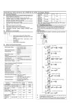
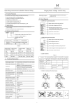
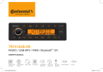
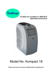
R
EN/IEC60947-5-1
Operating Instructions for ZHRV2 Series Relay
Function Features
Utilisation category
Controls its own supply voltage(True RMS measurement).
Control status is indicated by a LED.
Loss of neutral.
Voltage measurement accuracy <=1%.
Measuring frequency :50/60Hz.
The relays are designed for clip-on mounting on
rail.
AC-15
Contact capacity
Ue/Ie:240V/1.5A,415V/0.95A
Output type
1 C/O
Mounting support
35mm symmetrical DIN rail conforming to
EN/IEC 60715
Applications
Panel Diagram
Control for connection of moving equipment (site equipment,agricultural
equipment, refrigerated trucks).
Control for protection of persons and equipment against the
consequences of reverse running.
R
ZHRV2-08
Protection against the risk of a driving load (phase failure).
Normal/emergency power supply switching.
1 Functions LED
Model and Connotation
1.15 1.20
ZHRV2
1.10
1.25
2
1.05
1.30
0.1
8
0.80
—
—
—
—
—
—
●
●
—
—
—
—
8%
2s
●
●
03
1.05...1.30 0.1s...10s
0.70...0.95 0.1s...10s
—
—
—
●
04
1.05...1.30 0.1s...10s
0.70...0.95 0.1s...10s
—
—
●
●
—
—
●
●
5%...15%
0.1s...10s
●
●
05
1.15
2s
0.85
2s
06
—
—
—
—
07
1.05...1.30 0.1s...10s
0.70...0.95 0.1s...10s
5%...15%
0.1s...10s
—
●
08
1.05...1.30 0.1s...10s
0.70...0.95 0.1s...10s
5%...15%
0.1s...10s
●
●
09
1.15
2s
0.85
2s
8%
2s
—
●
10
1.15
2s
0.85
2s
8%
2s
●
●
11
1.05...1.30
2s
0.70...0.95
2s
8%
2s
●
●
220V,230V,240V,380V,400V,415VAC +/-30%
50/60Hz
Overvoltage range
1.05...1.30Ue
Undervoltage range
0.70...0.95Ue
Voltage hysteresis
P-P:6V,P-N:3.5V
II. Setting knob:
a. ×Ue: knob for setting of threshold values of overvoltage (1.05...1.30) or
under-voltage (0.70...0.95).
b. t(s): operation time delay adjusting knob 0.1s...10s.
c. Over_t(s): overvoltage operation time delay adjusting knob 0.1s...10s.
d. Under_t(s): undervoltage operation time delay adjusting knob 0.1s...
10s.
e.Asm (%): knob for setting of threshold value of unbalance 5%...15%.
Over-voltage threshold value = set value × Ue
Under - voltage threshold value = set value × Ue
Umax - Umin
Asymmetry value=
Ue
Umax: maximum phase voltage value ; Umin : minimum phase voltage value .
Function diagram
Phase failure and phase equence function diagram
Phase failure
L1
Asymmetry range
5%...15%
Asymmetry hysteresis
25%Asymmetry setting value
L2
Tripping time delay
Adjustable 0.1s...10s,10%
L3
Measurement error
<=1%over the whole range with voltage variation
Konb setting accuracy
1%of scale value
Rated insulation voltage
415V
Phase failure sensitivity
0.5Un
IP degree of protection
IP20
Pollution degree
3
Electrical durability
100000 cycles
Mechanical durability
1000000 cycles
Height above sea level
<=2000m
Operation temperature
-20℃...70℃
Relative humidity
<=50%(40℃)
Storage temperature
-25...75℃
Conventional heat current
5A
Asm(%)
Description of panel diagram:
Technical Parameters
Control ciruit frequency
15
5
I. Function LED:
a. Normal: no fault of relay indicated.
b. >U: overvoltage fault indication
c. U<: undervoltage fault indication
d. Phs.Seq: indication of input phase sequence errors
e. PhsFail: indication of phase failure fault
f. Asm: three-phase asymmetry fault indication
g. >U/<U: in case of over-voltage fault, the LED would be constantly ON ;
in case of under - voltage, the fault LED would flash .
h. >U/<U/Rst : when overvoltage fault occurs , the LED would flash at
a high frequency flash (once every 0.3s) ; in case of undervoltage
fault, the LED would flash at a low frequency (once every 1.5s) ; in case
of recovery delay , the LED would be constantly ON .
Note:●this function is available,and — this function is not availble.
Rated supply voltage
0.95
×Ue
Table 1
01
0.90
0.70
FuncPhase
Over-voltage
Asymmetry
Under-voltage
Phase
tion
sequcode Setting range Time delay Setting range Time delay Setting range Time delay ence failure
02
t(s)
10
0.85
0.75
2 Setting knob
10
×Ue
Rated control supply voltage codes :
A380,A400,A415,N220,N230,N240
A380:380VAC, A440:400VAC, A415:415VAC (P-P)
N220:220VAC, N230:230VAC, N240:240VAC (P-N)
Function code 01...11(see Table 1)
ZHRV2 series relay
6
4
Phase sequence
L1
L3
L1
L3
L2
L2
L2
L1
L3
14
11
12
Overvoltage and undervoltage function diagram
>U
Hysteresis
Hysteresis
<U
L1/L2/L3
14
To
Tu
<Tu
11
12
To:Overvoltage threshold tripping delay.
Tu:Undervoltage threshold tripping delay.
-1-
<To
Asymmetry function diagram
Set point
asymmetry
Hysteresis
0%
<Ta
Ta
14
11
12
Ta:Asymmetry threshold tripping delay.
Operating Instructions
1.Operation threshold value and operation time delay is set through setting
knob.
2.If relay detects faults during electrification, the output relay would maintain an "off-state".
3.In case of voltage fault, the relay would be disconnected after the set delay time elapses.
4.When measured voltage <= 0.5Ue, phase failure fault must have occurred .
5.When measured voltage value >= 1.5Ue, the relay would operate immediately.
Overall Dimensions
L1
L2
L3
R
14
11
12
36
66.5max
Wiring Diagram
3 phase 3 wire
3 phase 4 wire
N L1 L2 L3
L1 L2 L3
F
F
F
F
L1 L2 L3 N
L1 L2 L3
KM
KM
14 11 12
Load
14 11 12
Load
Warning
1. This product shall be installed , operated and maintained by professional personnel.
2 . Whether or not the product functions normally , user shall not dismantle or repair the said product without permission, and we shall not assume any responsibility for the accident as a result thereof.
3 . Please refer to the wiring diagram in Operation Instructions when arranging wires.
4 . Never place power input line in the same conduit with other wires with heavy current. Please use shielded wire if necessary so as not to bring about interference that may influence the normal operation of relay.
5 . Do not use this product in areas with dust , corrosive gases and with exposure to direct sunlight and rain.
6 . Never use this product in medium with explosion hazard and with gases that may corrode metals and destroy the insulation, and do not use this product in a space
with conductive dust.
7 . Please store and use this product at rated supply voltage and stated temperature , height above sea level and humidity .
8 . Failure to follow these instructions can result in death, serious injury, or equipment damage.
9. The warranty period of this product shall be 18 months under normal use .
-2-
http :// www.chtce.com