1
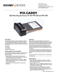
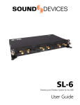
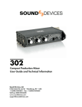
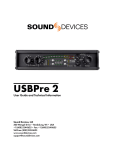
CL-6 Packing List
Thank you for purchasing the CL-6 Input Controller for the 664. Please make certain that this package
contains the listed items below.
1) CL-6 Input Controller
1) 10-pin ribbon cable with captive rubber gasket
3) 2” screws
1) Bag of colored stickers for fader knobs
1) Replacement Protective Cover with adhesive backing
1) User Guide
CL-6 Controller
User Guide and Technical Information
Sound Devices, LLC
E7556 State Road 23 and 33 • Reedsburg, WI • USA
+1 (608) 524-0625 • fax: +1 (608) 524-0655
Toll-Free: (800) 505-0625
www.sounddevices.com
[email protected]
CL-6 User Guide and Technical Information
The CL-6 Input Controller connects to the top or bottom of the 664 (see Mounting the CL-6) and includes 6 full-sized fader controls, PFL control, and highpass control, and dedicated L and R routing
buttons for Inputs 7-12. The large, backlit Record and Stop buttons provide convenient access to transport functions. Other features include large, daylight-viewable LED meters (with track arm indicators)
for tracks L, R, X1, and X2.
This User Guide is a supplement to the 664 User Guide. For full details please refer to the latest 664 User
Guide available online at http://www.sounddevices.com/download/guides/664_en.pdf
Mounting the CL-6
The CL-6 Input Controller can be mounted to the top or bottom of the 664. The following installation
instructions are the same whether mounting on the top or bottom. Begin by choosing which side the
CL-6 will be mounted to and all directions will apply to that side of the 664.
1. Power down the 664.
2. Remove the disposable protective cover from the 664’s Header using a small, flat tool (A jeweler’s screwdriver works well). The protective cover is attached with adhesive.
3. Similarly, remove the disposable protective cover from the CL-6 Header on the side that will
connect to the 664.
4. Using a Philip’s head screwdriver, remove one of the rear screws from the CL-6 (see diagram). Either screw can be removed. Remove only one rear screw. This screw will not be
used with the CL-6/664 assembly.
5. Using a Philip’s head screwdriver, remove the rear screw on the 664 that corresponds with
the screw removed in step 3. The CL-6 can be mounted upside down. Ensure that the screw
removed in this step corresponds to the desired orientation. This screw will not be used
with the CL-6/664 assembly.
6. Using a Philip’s head screwdriver, remove the left and right screws from the 664 (see diagram). These screws will not be used with the CL-6/664 assembly.
7. Connect the ribbon cable (supplied) to the Header on the 664. Carefully slide the rubber gasket into place where the ribbon cable connects to the 664.
8. With the 664 sitting on a flat, stable surface, hold the CL-6 in hand and connect the other end
of the ribbon cable to the header on the CL-6.
9. Insert the excess ribbon cable into the cavity behind the header on the CL-6 while lowering the CL-6 into position. Ensuring that the ribbon cable is fully within the cavity and not
pinched between the CL-6 and 664, and that the rubber gasket is positioned properly.
10. Using a philip’s head screwdriver, drive the 3 longer screws (supplied) through the CL-6 and
into the 664.
1
CL-6 User Guide and Technical Information
Left Screw
Multi-pin Header (Covered)
Right Screw
Rear screws
Multi-pin Header (Exposed)
Front Panel Description
4
5
1
6
7
2
8
9
3
10
11
1) Input Fader
5) Input LED
Primary control for adjusting the level of an
Indicates input signal activity. Illuminates in
input during operation. Ranges from off to +15
various colors and intensities to show signal
dB. Nominal setting is in the middle (0 dB).
level and activity. Green = signal presence (prefader), yellow = limiter activity (pre- and post2) Highpass Filter Button
fade), red = signal overload/clipping (pre- and
Push to toggle activation of Highpass Filter on
post-fade), flashing yellow = input PFL.
the Input.
6) Track R Indicator
3) Highpass Filter LED
Illuminates Blue when the Input has been
Illuminates blue to indicate Highpass filter is
routed to Track R.
engaged on the Input.
4) Track L Indicator
Illuminates Blue when the Input has been
routed to Track L.
2
Features and specifications are subject to change. Visit www.sounddevices.com for the latest documentation.
CL-6 User Guide and Technical Information
7) PFL / Input Select Switch
9) LED Bus Track Meters
Slide left: Pre-Fade Listen. Sends the input’s
Displays levels for L, R, X1, and X2 Tracks.
pre-fade signal to HP monitor mono mix. The
When the CL-6 is attached, these Track meters
664 supports simultaneous PFL of multiple
are removed from the LCD, which instead disinputs. Does not affect Master Output signal.
plays Inputs 1-12.
Slide the switch left to activate, and again to
10) Record Button
deactivate. For momentary action, hold the
Alternate, backlit Record Button. The Transport
switch left for one second or longer. The Input
Control on the 664 operates normally when the
LED flashes yellow when an input’s PFL is acCL-6 is attached. This button provides an adtive. Slide right: Input Settings. Enters the Input
ditional control point for Record.
Settings Screen where basic input setup and
input-to-output bus routing is performed. See 11) Stop Button
Input Setup and Control.
Alternate, backlit Stop Button. The Transport
Control on the 664 operates normally when the
8) Bus Track Arm LED’s
CL-6 is attached. This button provides an adIlluminate red to indicate the Track is armed
ditional control point for Stop.
for recording.
Operation
When the CL-6 is connected, the TA3 connections for Direct Inputs 1-6 on the 664 become available for
balanced, line-level input. These Inputs are numbered 7-12 respectively. Routing, ISO Track arming,
and Fader control all function the same as Inputs 1-6. see Input Setup and Control
Bus Track meters (L, R, X1, and X2) are removed from the Main Screen to make room for the meters of
Inputs 7-12:
Trim Levels
To adjust the trim level of Inputs 7-12, slide the Input’s Input Select Switch right to access the Input
Settings Screen. From the Input Settings Screen, turn the Select Encoder to adjust trim for the Input.
The trim gain will be displayed:
3
CL-6 User Guide and Technical Information
Direct Outputs 1-6
By default when the CL-6 is connected, the TA3 connections for Inputs 7-12 will function as balanced,
line-level inputs. It is possible to switch each connection independently back to a direct output for its
respective 1-6 Input. Slide the desired input 7-12 Input Select Switch right to access the Input Settings
Screen. Press the Headphone Encoder and turn it to select the DIR OUT option.
Bus Tracks (L, R, X1, and X2)
To make arming and level adjustments to the bus tracks, press the Meters repeatedly from Main
Screen until a Meter View is shown that displays the bus tracks (see “Meter Views” in 664 User Guide).
Turn the Select Encoder to highlight the desired Bus Track. With the desired track highlighted, press
the Select Encoder and turn to adjust that track’s level. To arm a track, turn the Select Encoder to highlight the track, press and hold the Meters Button, then push the Select Encoder.
4
Features and specifications are subject to change. Visit www.sounddevices.com for the latest documentation.
CL-6 User Guide and Technical Information
Quick L and R Track routing
To quickly route an input to the L or R Bus track, hold down the Input’s Highpass Filter Button, then
slide the Input Select Switch left for Track L or right for Track R. The Track L or Track R Indicator LED
will illuminate to indicate that the Input is routed to the respective track.
Highpass Filter
To engage the Highpass Filter, push the Highpass Filter Button for the desired Input. The Highpass
Filter LED will illuminate to indicate the filter is activated. Push the Highpass Filter button again to
disable the Highpass Filter.
5
CL-6 User Guide and Technical Information
Specifications
Powering
Powered by the 664.
Dimensions
1.75” x 10.2” x 2.25” (H x W x D)
Weight
21.5 oz.
Declaration of Conformity
According to EN ISO/IEC 17050-1:2004
Manufacturer’s Name:
Sound Devices, LLC
Manufacturer’s Address:
E7556 State Rd. 23 and 33
Reedsburg, WI 53959
USA
Declares under sole responsibility that the product as delivered
Product Name:
CL-6 Input Controller
Model Number:
CL-6
Product Options:
This declaration covers all options of the above products
complies with the essential requirements of the following applicable European Directives, and carries the CE marking
accordingly:
EMC Directive (2004/108/EC)
EN 55022:2006 + A1:2007
EN 55103-2:2009
First date of CE approval October 17, 2012.
This Declaration of Conformity applies to the above-listed products placed on the EU market after:
October 17, 2012
Date
6
Matt Anderson
Director of Engineering
Features and specifications are subject to change. Visit www.sounddevices.com for the latest documentation.
CL-6 User Guide and Technical Information
Warranty and Technical Support
Warranty & Service
Sound Devices, LLC warrants the CL-6 against defects in materials and workmanship for a period of
TWO (2) years from date of original retail purchase.
This is a non-transferable warranty that extends only to the original purchaser. Sound Devices, LLC
will repair or replace the product at its discretion at no charge. Warranty claims due to severe service
conditions will be addressed on an individual basis.
THE WARRANTY AND REMEDIES SET FORTH ABOVE ARE EXCLUSIVE. SOUND DEVICES, LLC
DISCLAIMS ALL OTHER WARRANTIES, EXPRESS OR IMPLIED, INCLUDING WARRANTIES OF
MERCHANTABILITY AND FITNESS FOR A PARTICULAR PURPOSE.
SOUND DEVICES, LLC IS NOT RESPONSIBLE FOR SPECIAL, INCIDENTAL, OR CONSEQUENTIAL DAMAGES ARISING FROM ANY BREACH OF WARRANTY OR UNDER ANY OTHER LEGAL THEORY. Because some jurisdictions do not permit the exclusion or limitations set forth above,
they may not apply in all cases.
For all service, including warranty repair, please contact Sound Devices for an RMA (return merchandise authorization) before sending your unit in for repair. Product returned without an RMA number
may experience delays in repair. When sending a unit for repair, please do not include accessories,
including SSD drives, CF cards, batteries, power supplies, carry cases, cables, or adapters unless instructed by Sound Devices.
Sound Devices, LLC
Service Repair RMA #XXXXX
E7556 State Road 23 and 33
Reedsburg, WI 53959 USA
telephone: (608) 524-0625
Technical Support / Bug Reports
For technical support and bug reporting on all Sound Devices products contact:
Sound Devices, LLC
E-mail: [email protected]
web: www.sounddevices.com/contact_support.htm
Telephone: +1 (608) 524-0625 / Toll-Free in the U.S.A.: (800) 505-0625
Fax: +1 (608) 524-0655
Sound Devices cannot guarantee that a given computer, software, or operating system configuration can be
used satisfactorily with CL-6 generated files based exclusively on the fact that it meets our minimum system
requirements. Please check with your software editing application to make certain that it is compatible with
the file type selected
7
CL-6 User Guide and Technical Information
Limitation of Liability
LIMITATION ON SOUND DEVICES’ LIABILITY. SOUND DEVICES, LLC SHALL NOT BE LIABLE TO THE PURCHASER OF THIS
PRODUCT OR THIRD PARTIES FOR DAMAGES, LOSSES, COSTS, OR EXPENSES INCURRED BY PURCHASER OR THIRD PARTIES AS A RESULT OF: ACCIDENT, MISUSE, OR ABUSE OF THIS PRODUCT OR UNAUTHORIZED MODIFICATIONS, REPAIRS,
OR ALTERATIONS TO THIS PRODUCT, OR FAILURE TO STRICTLY COMPLY WITH SOUND DEVICES, LLC’S OPERATING AND
INSTALLATION INSTRUCTIONS. TO THE FULLEST EXTENT PERMITTED BY LAW, SOUND DEVICES SHALL HAVE NO LIABILITY
TO THE END USER OR ANY OTHER PERSON FOR COSTS, EXPENSES, DIRECT DAMAGES, INCIDENTAL DAMAGES, PUNITIVE
DAMAGES, SPECIAL DAMAGES, CONSEQUENTIAL DAMAGES OR OTHER DAMAGES OF ANY KIND OR NATURE WHATSOEVER
ARISING OUT OF OR RELATING TO THE PRODUCTS, THESE TERMS AND CONDITIONS OR THE PARTIES’ RELATIONSHIP,
INCLUDING, WITHOUT LIMITATION, DAMAGES RESULTING FROM OR RELATED TO THE DELETION OR OTHER LOSS OF AUDIO
OR VIDEO RECORDINGS OR DATA, REDUCED OR DIMINISHED AUDIO OR VIDEO QUALITY OR OTHER SIMILAR AUDIO OR
VIDEO DEFECTS ARISING FROM, RELATED TO OR OTHERWISE ATTRIBUTABLE TO THE PRODUCTS OR THE END USER’S USE
OR OPERATION THEREOF, REGARDLESS OF WHETHER SUCH DAMAGES ARE CLAIMED UNDER CONTRACT, TORT OR ANY
OTHER THEORY. “CONSEQUENTIAL DAMAGES”s FOR WHICH SOUND DEVICES SHALL NOT BE LIABLE SHALL INCLUDE, WITHOUT LIMITATION, LOST PROFITS, PENALTIES, DELAY DAMAGES, LIQUIDATED DAMAGES AND OTHER DAMAGES AND LIABILITIES WHICH END USER SHALL BE OBLIGATED TO PAY OR WHICH END USER OR ANY OTHER PARTY MAY INCUR RELATED TO
OR ARISING OUT OF ITS CONTRACTS WITH ITS CUSTOMERS OR OTHER THIRD PARTIES. NOTWITHSTANDING AND WITHOUT
LIMITING THE FOREGOING, IN NO EVENT SHALL SOUND DEVICES BE LIABLE FOR ANY AMOUNT OF DAMAGES IN EXCESS
OF AMOUNTS PAID BY THE END USER FOR THE PRODUCTS AS TO WHICH ANY LIABILITY HAS BEEN DETERMINED TO EXIST. SOUND DEVICES AND END USER EXPRESSLY AGREE THAT THE PRICE FOR THE PRODUCTS WAS DETERMINED IN CONSIDERATION OF THE LIMITATION ON LIABILITY AND DAMAGES SET FORTH HEREIN AND SUCH LIMITATION HAS BEEN SPECIFICALLY BARGAINED FOR AND CONSTITUTES AN AGREED ALLOCATION OF RISK WHICH SHALL SURVIVE THE DETERMINATION
OF ANY COURT OF COMPETENT JURISDICTION THAT ANY REMEDY HEREIN FAILS OF ITS ESSENTIAL PURPOSE.
8
Features and specifications are subject to change. Visit www.sounddevices.com for the latest documentation.
CL-6 Rev. 1.02