1
SmartFusion2 SoC FPGA High Speed
Serial and DDR Interfaces
User’s Guide
SmartFusion2 SoC FPGA High Speed Serial and DDR Interfaces User’s Guide
Table of Contents
1 SERDESIF Block . . . . . . . . . . . . . . . . . . . . . . . . . . . . . . . . . . . . . . . . . . . . . . . . . . . . . . . . . . . . . . . . . .-5
Functional Description . . . . . . . . . . . . . . . . . . . . . . . . . . . . . . . . . . . . . . . . . . . . . . . . . . . . . . . . . . . . . . . . . . . . . . . 5
SmartFusion2 SoC FPGA Serial Protocols Overview . . . . . . . . . . . . . . . . . . . . . . . . . . . . . . . . . . . . . . . . . . . . . . . 7
Clocking and Reset . . . . . . . . . . . . . . . . . . . . . . . . . . . . . . . . . . . . . . . . . . . . . . . . . . . . . . . . . . . . . . . . . . . . . . . . 21
Configuration of SERDESIF . . . . . . . . . . . . . . . . . . . . . . . . . . . . . . . . . . . . . . . . . . . . . . . . . . . . . . . . . . . . . . . . . . 25
I/O Signal Interface of SERDESIF . . . . . . . . . . . . . . . . . . . . . . . . . . . . . . . . . . . . . . . . . . . . . . . . . . . . . . . . . . . . . 44
SERDESIF Debug Interface . . . . . . . . . . . . . . . . . . . . . . . . . . . . . . . . . . . . . . . . . . . . . . . . . . . . . . . . . . . . . . . . . 56
Glossary . . . . . . . . . . . . . . . . . . . . . . . . . . . . . . . . . . . . . . . . . . . . . . . . . . . . . . . . . . . . . . . . . . . . . . . . . . . . . . . . . 58
2 PCI Express . . . . . . . . . . . . . . . . . . . . . . . . . . . . . . . . . . . . . . . . . . . . . . . . . . . . . . . . . . . . . . . . . . . . .-59
Fully compliant physical layer device (PHY), physical coding sub-layer (PCS) . . . . . . . . . . . . . . . . . . . . . . . . . . . 59
PCIe Endpoint . . . . . . . . . . . . . . . . . . . . . . . . . . . . . . . . . . . . . . . . . . . . . . . . . . . . . . . . . . . . . . . . . . . . . . . . . . . . 59
PCIe System . . . . . . . . . . . . . . . . . . . . . . . . . . . . . . . . . . . . . . . . . . . . . . . . . . . . . . . . . . . . . . . . . . . . . . . . . . . . . 61
SERDESIF System Registers for PCIe Mode . . . . . . . . . . . . . . . . . . . . . . . . . . . . . . . . . . . . . . . . . . . . . . . . . . . . 67
Using the PCIe System . . . . . . . . . . . . . . . . . . . . . . . . . . . . . . . . . . . . . . . . . . . . . . . . . . . . . . . . . . . . . . . . . . . . . 70
SmartFusion2 SoC FPGA PCIe Power Management . . . . . . . . . . . . . . . . . . . . . . . . . . . . . . . . . . . . . . . . . . . . . . 79
PCIe Core Bridge Register Space . . . . . . . . . . . . . . . . . . . . . . . . . . . . . . . . . . . . . . . . . . . . . . . . . . . . . . . . . . . . . 83
PCIe System – I/O Signal Interface . . . . . . . . . . . . . . . . . . . . . . . . . . . . . . . . . . . . . . . . . . . . . . . . . . . . . . . . . . . 118
Appendix A: PCIe Configuration Space . . . . . . . . . . . . . . . . . . . . . . . . . . . . . . . . . . . . . . . . . . . . . . . . . . . . . . . . 122
Glossary . . . . . . . . . . . . . . . . . . . . . . . . . . . . . . . . . . . . . . . . . . . . . . . . . . . . . . . . . . . . . . . . . . . . . . . . . . . . . . . . 127
3 XAUI . . . . . . . . . . . . . . . . . . . . . . . . . . . . . . . . . . . . . . . . . . . . . . . . . . . . . . . . . . . . . . . . . . . . . . . . . .-129
SERDESIF System Registers Configurations for XAUI Mode . . . . . . . . . . . . . . . . . . . . . . . . . . . . . . . . . . . . . . .
Using the XAUI Protocol Mode . . . . . . . . . . . . . . . . . . . . . . . . . . . . . . . . . . . . . . . . . . . . . . . . . . . . . . . . . . . . . .
SmartFusion2 SoC FPGA XAUI – Timing Diagram . . . . . . . . . . . . . . . . . . . . . . . . . . . . . . . . . . . . . . . . . . . . . . .
MDIO Register Map . . . . . . . . . . . . . . . . . . . . . . . . . . . . . . . . . . . . . . . . . . . . . . . . . . . . . . . . . . . . . . . . . . . . . . .
SmartFusion2 SoC FPGA XAUI - I/O Signal Interface . . . . . . . . . . . . . . . . . . . . . . . . . . . . . . . . . . . . . . . . . . . .
Glossary . . . . . . . . . . . . . . . . . . . . . . . . . . . . . . . . . . . . . . . . . . . . . . . . . . . . . . . . . . . . . . . . . . . . . . . . . . . . . . . .
133
134
139
141
147
152
4 EPCS Interface. . . . . . . . . . . . . . . . . . . . . . . . . . . . . . . . . . . . . . . . . . . . . . . . . . . . . . . . . . . . . . . . . .-153
Using EPCS Protocol Mode . . . . . . . . . . . . . . . . . . . . . . . . . . . . . . . . . . . . . . . . . . . . . . . . . . . . . . . . . . . . . . . . .
SmartFusion2 SoC FPGA EPCS Interface – Timing Diagram . . . . . . . . . . . . . . . . . . . . . . . . . . . . . . . . . . . . . . .
SERDESIF System Registers Configurations for EPCS Mode . . . . . . . . . . . . . . . . . . . . . . . . . . . . . . . . . . . . . .
SmartFusion2 SoC FPGA EPCS Mode – I/O Signal Interface . . . . . . . . . . . . . . . . . . . . . . . . . . . . . . . . . . . . . .
Glossary . . . . . . . . . . . . . . . . . . . . . . . . . . . . . . . . . . . . . . . . . . . . . . . . . . . . . . . . . . . . . . . . . . . . . . . . . . . . . . . .
158
162
163
164
168
5 Serializer/Deserializer . . . . . . . . . . . . . . . . . . . . . . . . . . . . . . . . . . . . . . . . . . . . . . . . . . . . . . . . . . . .-169
SERDES Functional Blocks . . . . . . . . . . . . . . . . . . . . . . . . . . . . . . . . . . . . . . . . . . . . . . . . . . . . . . . . . . . . . . . . .
TX PLL and CDR PLL Operation . . . . . . . . . . . . . . . . . . . . . . . . . . . . . . . . . . . . . . . . . . . . . . . . . . . . . . . . . . . . .
SERDES Testing Operation . . . . . . . . . . . . . . . . . . . . . . . . . . . . . . . . . . . . . . . . . . . . . . . . . . . . . . . . . . . . . . . . .
SERDES Block Register . . . . . . . . . . . . . . . . . . . . . . . . . . . . . . . . . . . . . . . . . . . . . . . . . . . . . . . . . . . . . . . . . . .
SERDESIF – I/O Signal Interface . . . . . . . . . . . . . . . . . . . . . . . . . . . . . . . . . . . . . . . . . . . . . . . . . . . . . . . . . . . .
Glossary . . . . . . . . . . . . . . . . . . . . . . . . . . . . . . . . . . . . . . . . . . . . . . . . . . . . . . . . . . . . . . . . . . . . . . . . . . . . . . . .
Revision 1
170
177
179
183
230
233
3
Table of Contents
6 DDR Controller . . . . . . . . . . . . . . . . . . . . . . . . . . . . . . . . . . . . . . . . . . . . . . . . . . . . . . . . . . . . . . . . . .-235
Address Mapping . . . . . . . . . . . . . . . . . . . . . . . . . . . . . . . . . . . . . . . . . . . . . . . . . . . . . . . . . . . . . . . . . . . . . . . . . 235
7 MSS DDR Subsystem . . . . . . . . . . . . . . . . . . . . . . . . . . . . . . . . . . . . . . . . . . . . . . . . . . . . . . . . . . . .-237
Introduction . . . . . . . . . . . . . . . . . . . . . . . . . . . . . . . . . . . . . . . . . . . . . . . . . . . . . . . . . . . . . . . . . . . . . . . . . . . . . 237
MDDR Subsystem Overview . . . . . . . . . . . . . . . . . . . . . . . . . . . . . . . . . . . . . . . . . . . . . . . . . . . . . . . . . . . . . . . . 238
Functional Description . . . . . . . . . . . . . . . . . . . . . . . . . . . . . . . . . . . . . . . . . . . . . . . . . . . . . . . . . . . . . . . . . . . . . 240
MDDR Configurations . . . . . . . . . . . . . . . . . . . . . . . . . . . . . . . . . . . . . . . . . . . . . . . . . . . . . . . . . . . . . . . . . . . . . 243
DDR PHY . . . . . . . . . . . . . . . . . . . . . . . . . . . . . . . . . . . . . . . . . . . . . . . . . . . . . . . . . . . . . . . . . . . . . . . . . . . . . . . 250
Memory Initialization . . . . . . . . . . . . . . . . . . . . . . . . . . . . . . . . . . . . . . . . . . . . . . . . . . . . . . . . . . . . . . . . . . . . . . 252
Data Flow Paths . . . . . . . . . . . . . . . . . . . . . . . . . . . . . . . . . . . . . . . . . . . . . . . . . . . . . . . . . . . . . . . . . . . . . . . . . . 253
MDDR Memory Map . . . . . . . . . . . . . . . . . . . . . . . . . . . . . . . . . . . . . . . . . . . . . . . . . . . . . . . . . . . . . . . . . . . . . . 259
DDR Memory Device Examples . . . . . . . . . . . . . . . . . . . . . . . . . . . . . . . . . . . . . . . . . . . . . . . . . . . . . . . . . . . . . 262
Register Interface . . . . . . . . . . . . . . . . . . . . . . . . . . . . . . . . . . . . . . . . . . . . . . . . . . . . . . . . . . . . . . . . . . . . . . . . . 265
Glossary . . . . . . . . . . . . . . . . . . . . . . . . . . . . . . . . . . . . . . . . . . . . . . . . . . . . . . . . . . . . . . . . . . . . . . . . . . . . . . . . 371
8 Fabric Double Data Rate Subsystem . . . . . . . . . . . . . . . . . . . . . . . . . . . . . . . . . . . . . . . . . . . . . . . . .-373
FDDR Subsystem Overview . . . . . . . . . . . . . . . . . . . . . . . . . . . . . . . . . . . . . . . . . . . . . . . . . . . . . . . . . . . . . . . .
FDDR Configuration . . . . . . . . . . . . . . . . . . . . . . . . . . . . . . . . . . . . . . . . . . . . . . . . . . . . . . . . . . . . . . . . . . . . . . .
Use Case Scenario . . . . . . . . . . . . . . . . . . . . . . . . . . . . . . . . . . . . . . . . . . . . . . . . . . . . . . . . . . . . . . . . . . . . . . .
Register Interface . . . . . . . . . . . . . . . . . . . . . . . . . . . . . . . . . . . . . . . . . . . . . . . . . . . . . . . . . . . . . . . . . . . . . . . . .
Glossary . . . . . . . . . . . . . . . . . . . . . . . . . . . . . . . . . . . . . . . . . . . . . . . . . . . . . . . . . . . . . . . . . . . . . . . . . . . . . . . .
373
378
378
382
393
9 DDR Bridge . . . . . . . . . . . . . . . . . . . . . . . . . . . . . . . . . . . . . . . . . . . . . . . . . . . . . . . . . . . . . . . . . . . .-395
Features . . . . . . . . . . . . . . . . . . . . . . . . . . . . . . . . . . . . . . . . . . . . . . . . . . . . . . . . . . . . . . . . . . . . . . . . . . . . . . . .
DDR Bridges in SmartFusion2 SoC FPGA Devices . . . . . . . . . . . . . . . . . . . . . . . . . . . . . . . . . . . . . . . . . . . . . .
Functional Description . . . . . . . . . . . . . . . . . . . . . . . . . . . . . . . . . . . . . . . . . . . . . . . . . . . . . . . . . . . . . . . . . . . . .
MSS DDR Bridge Configurations . . . . . . . . . . . . . . . . . . . . . . . . . . . . . . . . . . . . . . . . . . . . . . . . . . . . . . . . . . . . .
MDDR/FDDR DDR Bridge Configuration Steps . . . . . . . . . . . . . . . . . . . . . . . . . . . . . . . . . . . . . . . . . . . . . . . . .
SYSREG Control Registers . . . . . . . . . . . . . . . . . . . . . . . . . . . . . . . . . . . . . . . . . . . . . . . . . . . . . . . . . . . . . . . . .
DDR Bridge Control Registers in MDDR and FDDR . . . . . . . . . . . . . . . . . . . . . . . . . . . . . . . . . . . . . . . . . . . . . .
Glossary . . . . . . . . . . . . . . . . . . . . . . . . . . . . . . . . . . . . . . . . . . . . . . . . . . . . . . . . . . . . . . . . . . . . . . . . . . . . . . . .
395
396
398
404
404
405
406
406
10 Soft Memory Controller Fabric Interface Controller . . . . . . . . . . . . . . . . . . . . . . . . . . . . . . . . . . . . . .-407
Introduction . . . . . . . . . . . . . . . . . . . . . . . . . . . . . . . . . . . . . . . . . . . . . . . . . . . . . . . . . . . . . . . . . . . . . . . . . . . . . 407
Functional Block Diagram . . . . . . . . . . . . . . . . . . . . . . . . . . . . . . . . . . . . . . . . . . . . . . . . . . . . . . . . . . . . . . . . . . 407
Functional Description . . . . . . . . . . . . . . . . . . . . . . . . . . . . . . . . . . . . . . . . . . . . . . . . . . . . . . . . . . . . . . . . . . . . . 408
SYSREG Control Register for SMC_FIC . . . . . . . . . . . . . . . . . . . . . . . . . . . . . . . . . . . . . . . . . . . . . . . . . . . . . . . 408
SMC_FIC Port List . . . . . . . . . . . . . . . . . . . . . . . . . . . . . . . . . . . . . . . . . . . . . . . . . . . . . . . . . . . . . . . . . . . . . . . . 409
Glossary . . . . . . . . . . . . . . . . . . . . . . . . . . . . . . . . . . . . . . . . . . . . . . . . . . . . . . . . . . . . . . . . . . . . . . . . . . . . . . . . 414
A List of Changes . . . . . . . . . . . . . . . . . . . . . . . . . . . . . . . . . . . . . . . . . . . . . . . . . . . . . . . . . . . . . . . . .-415
B Product Support . . . . . . . . . . . . . . . . . . . . . . . . . . . . . . . . . . . . . . . . . . . . . . . . . . . . . . . . . . . . . . . . .-417
Customer Service . . . . . . . . . . . . . . . . . . . . . . . . . . . . . . . . . . . . . . . . . . . . . . . . . . . . . . . . . . . . . . . . . . . . . . . .
Customer Technical Support Center . . . . . . . . . . . . . . . . . . . . . . . . . . . . . . . . . . . . . . . . . . . . . . . . . . . . . . . . . .
Technical Support . . . . . . . . . . . . . . . . . . . . . . . . . . . . . . . . . . . . . . . . . . . . . . . . . . . . . . . . . . . . . . . . . . . . . . . .
Website . . . . . . . . . . . . . . . . . . . . . . . . . . . . . . . . . . . . . . . . . . . . . . . . . . . . . . . . . . . . . . . . . . . . . . . . . . . . . . . .
Contacting the Customer Technical Support Center . . . . . . . . . . . . . . . . . . . . . . . . . . . . . . . . . . . . . . . . . . . . . .
ITAR Technical Support . . . . . . . . . . . . . . . . . . . . . . . . . . . . . . . . . . . . . . . . . . . . . . . . . . . . . . . . . . . . . . . . . . . .
4
R e vi s i o n 1
417
417
417
417
417
418
1 – SERDESIF Block
SmartFusion®2 system-on-chip (SoC) field programmable gate array (FPGA) high speed serial interface,
also known as SERDESIF, integrates functionality to support multiple high speed serial protocols. The
protocols supported in SmartFusion2 SoC FPGA devices are peripheral component interconnect
express (PCI Express®), eXtended attachment unit interface (XAUI), and serial gigabit media
independent interface (SGMII). In addition, any user defined high serial protocol implemented in the
SmartFusion2 SoC FPGA fabric can access SERDES lanes through the external physical coding
sublayer (EPCS) interface. The SERDESIF block can be configured to support single or multiple serial
protocol modes of operation. In multiple serial protocol mode, two protocols can be implemented on the
four physical lanes of the SERDESIF block.The SERDESIF block is connected to the FPGA fabric
through an AXI/AHBL interface or EPCS interface.
Functional Description
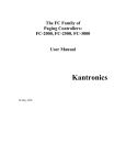
SmartFusion2 SoC FPGA devices have two hard high-speed serial interface blocks (SERDESIF0 and
SERDESIF1). These SERDESIF blocks interface with fabric, program control, and four SERDES
differential I/O pads. The program control interface can not be accessed, so it is not described in this
chapter. Figure 1-1 on page 6 shows the simplified view of the SmartFusion2 SoC FPGA SERDESIF
block. Depending on the protocol implemented, the SERDESIF blocks allow AXI/AHB/APB/EPCS
interface to the fabric. Each of these SERDESIF blocks instantiate the following blocks:
•
SERDES: This block implements the physical media attachment layer (PMA) and physical coding
sub-layer (PCS) of PCIe protocols. This PCS layer interface is compliant to the Intel PIPE 2.0
specification. It also implements the PMA calibration and control logic. The PCIe PCS
functionality can be bypassed completely in order to use the SERDES lanes for protocols other
than PCIe. This allows to use the PMA in various PHY modes and implement various protocols in
the SmartFusion2 SoC FPGA device. Refer to the "Serializer/Deserializer" section on page 169
for more information on the SERDES block.
•
PCIe system: This block implements the x1, x2, x4 lane PCIe endpoint (Regular and Reverse
mode) with an AXI/AHB interface to the fabric. The SmartFusion2 SoC FPGA PCIe is compliant
with the PCIe Base Specification 1.1 for Gen1 and PCIe Base Specification 2.0 for Gen1 or Gen2.
Refer to the "PCI Express" section on page 59 for more information on the PCIe system block.
•
XAUI Extender: This block is an XGMII extender to support the XAUI protocol through a soft IP
core in the SmartFusion2 SoC FPGA fabric. Refer to the "XAUI" section on page 129 for more
information.
•
SERDESIF system register: The SERDESIF system registers control the SERDESIF module for
single protocol or multi-protocol support implementation. These registers can be accessed
through the 32-bit APB interface and the default values of these registers can be configured using
Libero® System-on-Chip (SoC) software.
Using the SERDESIF blocks, SmartFusion2 SoC FPGA devices allow to implement the following high
speed protocols:
•
PCIe
•
XAUI protocol (10 GbE)
•
SGMII
•
User defined high speed protocols
Table 1-1 on page 7 lists the single protocol and multi-protocol implementations in the SERDESIF block,
also known as PHY modes of operation.
Revision 1
5
SERDESIF Block
SERDES
(PMA+PCIE
PCS)
SERDESIF
Block
X2 EPCS
Interface
X2 EPCS
Interface
XGMII Interface
SERDESIF
System
Register
PCIe
System IP
EPCS Lane 0 and Lane 1
XGMII Interface
XGMII Interface
PCIe L2/P2 AXI/AHB AXI/AHB
Master
Slave
Control
Interface Interface
EPCS
Lane 0 and
Lane 1
APB Slave
Interface
EPCS
Lane 2 and Lane 3
XGMII
Interface
FABRIC
XGMII
Interface
Figure 1-1 • SmartFusion2 SoC FPGA SERDESIF Block
6
XAUI
Extender
EPCS
x4-Lane
EPCS Lane 2 and Lane 3
SERDES
I/O-PADS
R e vi s i o n 1
SmartFusion2 SoC FPGA High Speed Serial and DDR Interfaces User’s Guide
Table 1-1 • SERDESIF Block usages in Single-Mode and Multi-Modes Protocols
Single/Multi-Protocol
Single protocol
Multi-protocol
Protocol
Description
PCIe
SERDESIF is configured to use PCIe x4, x2, and x1 link mode. The PCIe
link can be configured in Regular or Reversed modes. In PCIe only mode,
unused lanes are forced to RESET state and the Extender XAUI block is
put in RESET state.
XAUI
SERDESIF is configured to use all four lanes. In XAUI mode, all the lanes
are used and the PCIe System is put in RESET state.
SGMII
SERDESIF is configured to use lane3 (only) for SGMII purposes. In
SGMII-only mode, lane0, lane1, and lane2 are not used and are forced to
the RESET state. The PCIe System and XAUI blocks are put in the
RESET state.
EPCS
SERDESIF is configured to use all four lanes. In EPCS-only mode, any
serial protocol can be run though the EPCS interface to fabric using the
EPCS interface. The PCIe System and XAUI blocks are put in the RESET
state.
PCIe + EPCS
The PCIe protocol can be run on a maximum of 2-serial physical lanes in
Regular and Reverse modes. Lane0 and lane1 of SERDESIF can be used
for PCIe. Lane2 and lane3 can be used for running user defined protocol
through EPCS interface from fabric.
PCIe + SGMII
The PCIe protocol can be run on a maximum of 2-serial physical lanes in
Regular and Reverse modes. Lane0 and lane1 of SERDESIF can be used
for PCIe. Lane3 can be used for running SGMII. In this mode, lane2 is not
used.
SmartFusion2 SoC FPGA Serial Protocols Overview
The SERDESIF block supports implementing multiple high speed serial protocols. Although each of the
serial protocols are unique, all of them are layered protocol stacks and the implementation can vary
greatly from one layer to the next layer. Typically, the physical layer consists of fixed functionality that is
common to multiple packet-based protocols, while the upper layers tend to be more customizable.
Revision 1
7
SERDESIF Block
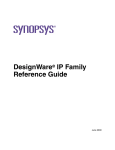
Figure 1-2 shows the functional partitioning of the physical and the upper layers of the high speed serial
protocols.
Upper Layer Functionality:
Aggregation and processing,
scheduling, bridging, memory
management etc.
PCS
Digital Logic Sub-block:
Encode/decode, link
state machines,
scrambling, alignment,
CTC
Physical
Layer
PMA
Electrical Sub-block:
SERDES, CDR, I/O
Figure 1-2 • Serial Protocol Partitioning Layers
8
R e vi s i o n 1
SmartFusion2 SoC FPGA High Speed Serial and DDR Interfaces User’s Guide
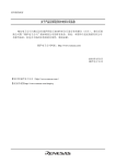
The advantage of being able to connect the FPGA logic and the SERDESIF blocks is that it allows
multiple serial protocols in the SmartFusion2 SoC FPGA devices. Figure 1-3 shows implementation of
PCIe, XAUI, and SGMII protocols using the SERDESIF block and FPGA fabric.
Link Width and Lane
Negotiation
Link Training
and Status
Reconciliation
XAUI State Machine
A/K/R Translation
CRC Generation
and Checking
Clock Tolerance
Compensation
GbE State Machine/
Auto Negotiation
Channel Alignment
(x4)
Physical Layer
Channel Alignment
8b/10b
Clock Tolerance
Compensation
MAC Layer
MAC Layer
Reconciliation
Scrambling/
Descrambling
Clock Tolerance
Compensation
MAC and Control
Physical Coding Sublayer
(PCS)
Framing
MAC and Control
Physical Coding Sublayer
(PCS)
Data Link Layer
(CRC, Control, DLLP)
Data Link Layer
Transaction Layer
Transaction
Layer
Application Layer
8b/10b
8b/10b
Word Alignment/
Link Sync
Word Alignment/
Link Sync
PMA (SERDES)
MDI
PCIe
Express
XAUI
PMA (SERDES)
MDI
Physical Medium
Attachment (PMA)
PMA (SERDES)
Physical Medium
Dependant (PMD)
Word Alignment/
Link Sync
SGMII
Figure 1-3 • Serial Protocol Using SERDESIF and FPGA Logic
The following sections briefly describe each of these serial protocols and their implementation in
SmartFusion2 SoC FPGA devices using the SERDESIF block.
Revision 1
9
SERDESIF Block
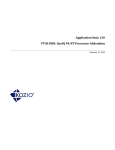
PCIe Endpoint
The SmartFusion2 SoC FPGA family supports PCIe endpoints. The PCIe endpoint supports PCIe Base
Specification 1.1 for Gen1 and PCIe Base Specification 2.0 for Gen1 (2.5 bps) or Gen2 (5.0 bps) protocol
with width of x1, x2 or x4. The application interface to the PCIe link is available through the FPGA and
can be programmed to AXI or AHB master and slave interfaces.
SERDES
I/O-PADS
SERDESIF
Block
SERDES
(PMA+PCIe
PCS)
SERDESIF
System
Register
PCIe
System IP
PCIe L2/P2 AXI/AHB AXI/AHB
Master
Slave
Control
Interface Interface
APB Slave
Interface
FABRIC
Figure 1-4 • SERDESIF Configuration for PCIe Protocol
10
R e visio n 1
SmartFusion2 SoC FPGA High Speed Serial and DDR Interfaces User’s Guide
Table 1-2 shows the possible options for implementing the PCIe link on four physical SERDES lanes.
Refer to the "PCI Express" section on page 59 for details on PCIe protocol implementation in
SmartFusion2 SoC FPGA devices.
Table 1-2 • Physical Interface Options for PCIe Endpoint in the SERDESIF Block
PHYSICAL SERDES LANES/LOGICAL LANES - Mapping
Lane0
Lane1
Lane2
Lane3
Speed
Speed
Speed
Speed
(bits per
(bits per
(bits per
(bits per
Protocol second) Protocol second) Protocol second) Protocol second)
PHY-MODE
Single Protocol
(PCIe Link mode)
Single Protocol
(PCIe Link Reversed mode)
Multi-Protocol
(PCIe Link mode)
Multi-Protocol
(PCIe Link Reversed mode)
PCIe
2.5 G
–
–
–
–
–
–
PCIe
2.5 G
PCIe
2.5 G
–
–
–
–
PCIe
2.5 G
PCIe
2.5 G
PCIe
2.5 G
PCIe
2.5 G
PCIe
5G
–
–
–
–
–
–
PCIe
5G
PCIe
5G
–
–
–
–
PCIe
5G
PCIe
5G
PCIe
5G
PCIe
5G
–
–
–
–
–
–
PCIe
2.5 G
–
–
–
–
PCIe
2.5 G
PCIe
2.5 G
–
–
–
–
–
–
PCIe
5G
–
–
–
–
PCIe
5G
PCIe
5G
PCIe
2.5 G
–
–
EPCS
–
EPCS*
–
PCIe
2.5 G
PCIe
2.5 G
EPCS*
–
EPCS
–
PCIe
5G
–
–
EPCS
–
EPCS
–
–
PCIe
5G
PCIe
5G
EPCS
–
EPCS*
–
–
PCIe
2.5 G
EPCS
–
EPCS
–
PCIe
2.5 G
PCIe
2.5 G
EPCS
–
EPCS
–
–
–
PCIe
5G
EPCS
–
EPCS
–
PCIe
5G
PCIe
5G
EPCS
–
EPCS
–
Note: * Lane3 EPCS interfaces are available in multi-protocol PHY mode and can be used for running
SGMII protocols.
Revision 1
11
SERDESIF Block
XAUI Protocol
The SERDES block in SERDESIF can be configured to support multiple serial protocols. The SERDES
block can be configured to bypass the PCS functionality and connect to the XAUI extender block and use
the 10 GbE (XAUI) protocol with a soft IP block in the FPGA.
Note: When the SERDESIF block is configured to support XAUI, it occupies all the four physical serial
lanes and it does not support any other protocol.
SERDES
I/O-PADS
SERDESIF
Block
SERDES
(PMA only)
X2 EPCS
Interface
X2 EPCS
Interface
XAUI
Extender
EPCS
x4-Lane
XGMII Interface
SERDESIF
System
Register
APB Slave
Interface
MDIO
Interface
GIGAbit
Ethernet
Soft IP
FABRIC
Figure 1-5 • SERDESIF Configuration for XAUI Protocol
Table 1-3 shows the configuration bandwidth for using XAUI in four physical SERDES lanes. Refer to the
"XAUI" section on page 129 for details on XAUI protocol implementation in SmartFusion2 SoC FPGA
devices.
Table 1-3 • Bandwidth for Implementing XAUI in SERDESIF Block
Lane0
XAUI Protocol
Single Protocol PHY mode
12
Lane1
Lane2
Speed
Speed
(bits per
(bits per
Protocol second) Protocol second) Protocol
XAUI
3.125 G
XAUI
3.125 G
R e visio n 1
XAUI
Lane3
Speed
(bits per
second)
Protocol
Speed
(bits per
second)
3.125 G
XAUI
3.125 G
SmartFusion2 SoC FPGA High Speed Serial and DDR Interfaces User’s Guide
SGMII Protocol
The SGMII protocol can be implemented in Single/Multiple-Protocol mode using the MAC block in the
microcontroller subsystem (MSS). In Single Protocol mode, the SGMII protocol can be implemented
using lane3 of the EPCS interface. Lane3 of the EPCS interface needs to be connected to the MSS
ethernet MAC through the CoreTBItoEPCS IP core block in the FPGA fabric.CoreTBItoEPCS appears
between TBI (Ten Bit Interface) and EPCS (External PCS). It has a Ten Bit transmit/receive interface on
TBI side and 20-bit transmit/receive interface on EPCS side. It will receive TBI data from MAC block and
transmit it towards the EPCS. It will also receive EPCS data and transmit it towards TBI.
In Multi-protocol mode, lane0 and lane1 of the SERDESIF block can be used for the PCIe protocol.
Table 1-4 shows the various options available for implementing SGMII in the SERDESIF block.
SERDESIF
Block
SERDES
(PMA only)
X2 EPCS
Interface
SERDESIF
System
Register
EPCS Lane 3 only
SERDES
I/O-PADS
APB Slave
Interface
CoreTBItoEPCS
FABRIC
Ethernet
MAC with
TBI Interface
MSS
Figure 1-6 • SERDESIF Configuration for SGMII Protocol
Revision 1
13
SERDESIF Block
Table 1-4 shows the various options for implementing SGMII protocol.
Table 1-4 • Various Options for Implementing SGMII in the SERDESIF Block
Lane0
SGMII Protocol
Single Protocol PHY mode
Multi-Protocol PHY mode
(PCIe Link Non-Reversed mode)
Multi-Protocol PHY mode
(PCIe Link Reversed mode)
14
Lane1
Lane2
Lane3
Speed
Speed
Speed
Speed
(bits per
(bits per
(bits per
(bits per
Protocol second) Protocol second) Protocol second) Protocol second)
–
–
–
–
–
–
SGMII
1.25 G
PCIe
2.5 G
–
–
–
–
SGMII
1.25 G
PCIe
2.5 G
PCIe
2.5 G
–
–
SGMII
1.25 G
PCIe
5G
–
–
–
–
SGMII
1.25 G
PCIe
5G
PCIe
5G
–
–
SGMII
1.25 G
–
–
PCIe
2.5 G
–
–
SGMII
1.25 G
PCIe
2.5 G
PCIe
2.5 G
–
–
SGMII
1.25 G
–
–
PCIe
5G
–
–
SGMII
1.25 G
PCIe
5G
PCIe
5G
–
–
SGMII
1.25 G
R e visio n 1
SmartFusion2 SoC FPGA High Speed Serial and DDR Interfaces User’s Guide
EPCS Protocol
By using the EPCS interface, any user defined serial protocol can be implemented in the SmartFusion2
SoC FPGA family. The SERDESIF block can be configured to bypass the embedded PCS logic in the
SERDES block and expose the EPCS interface to the fabric. The user-defined IP block in the FPGA
fabric can be connected to this EPCS interface.
SERDES
I/O-PADS
SERDES
(PMA only)
SERDESIF
Block
X2 EPCS
Interface
X2 EPCS
Interface
SERDESIF
System
Register
APB Slave
Interface
EPCS Lane 0
and Lane 1
EPCS Lane 2
and Lane 3
User IP
FABRIC
Figure 1-7 • SERDESIF Configuration for EPCS Protocol
Refer to the "EPCS Interface" section on page 153 for more information on EPCS implementation in
SmartFusion2 SoC FPGA families.
Revision 1
15
SERDESIF Block
In summary, the four SERDES physical lanes can be configured to run different serial protocols, resulting
in different modes of operation. Table 1-5 summarizes the various modes of operation of the SERDESIF
block.
Table 1-5 • Various Serial Protocol Implementation SmartFusion2 SoC FPGA Devices
PHY Physical Lanes
Lane0
Serial Protocol
PCIe protocol only mode
Modes
Lane2
Lane3
PHY Logical Lanes Vs Logical Lanes
PHY
Mode
PCIe (x4)
PCIe
Lane0
PCIe
Lane1
PCIe
Lane2
PCIe
Lane3
M0
PCIe (x2)
PCIe
Lane0
PCIe
Lane1
–
–
M1
PCIe (x1)
PCIe
Lane0
–1
–
–
M2
PCIe Reversed mode (x4)
PCIe
Lane3
PCIe
Lane2
PCIe
Lane1
PCIe
Lane0
M3
PCIe Reversed mode (x2)
–
–
PCIe
Lane1
PCIe
Lane0
M4
PCIe Reversed mode (x1)
–
–
–
PCIe-0
M5
PCIe Reversed mode (x2)
PCIe
Lane01
PCIe
Lane0
–
–
M6
PCIe Reversed mode (x1)
–
PCIe
Lane0
–
–
M7
XAUI-0
XAUI-1
XAUI-2
XAUI-3
M8
–
–
–
SGMII
M9
EPCS
EPCS
EPCS
EPCS
M10
PCIe
Lane0
PCIe
Lane01
EPCS
EPCS
M11
PCIe
Lane0
–1
EPCS
EPCS
M12
PCIe Reversed mode (x2)
PCIe
Lane01
PCIe
Lane0
EPCS
EPCS
M13
PCIe Reversed mode (x1)
–
PCIe
Lane0
EPCS
EPCS
M14
XAUI only
XAUI (x4 lane)
SGMII only
–
EPCS only
All lanes are used for user
defined protocol
Multi-Protocol (PCIe and EPCS) PCIe (x2)
(SGMII or EPCS can be
supported on lane2 and lane3)
PCIe (x1)
Notes:
1. Lane Tx-clk is used for lane0 for PCIe protocol purposes.
2. In multi-protocol mode, EPCS is available only on lane2 and lane3.
16
Lane1
R e visio n 1
SmartFusion2 SoC FPGA High Speed Serial and DDR Interfaces User’s Guide
Serial Protocols Setting Using the SERDESIF System Registers
The SERDESIF is configured to support various modes of operation. This configuration of the protocols
is through the SERDESIF system registers. These registers are configured using the APB interface. To
facilitate the configuration a GUI in Libero SoC is provided.
Table 1-6 • PCIe Mode Settings Using the SERDESIF System Register
SERDESIF System APB
Registers
Description
CONFIG_PHY_MODE[15:12] For each lane, this signal selects the protocol default settings which will set the reset
value of the register space.
CONFIG_PHY_MODE [15:12] – Defines lanelane3 settings
0000: PCIe mode lane3
0001: XAUI1 mode lane3
0010: EPCS2 (SGMII3) mode lane3
0011: EPCS (2.5 GHz) mode lane3
0100: EPCS (1.25 GHz) mode lane3
0101: EPCS (undefined) mode lane3
1111: SERDES PHY lane3 is off
CONFIG_PHY_MODE[11:8]
CONFIG_PHY_MODE [11:8] – Defines lane2 settings
0000: PCIe mode lane2
0001: XAUI mode lane2
0011: EPCS (2.5 GHz) mode lane2
0100: EPCS (1.25 GHz) mode lane2
0101: EPCS (undefined) mode lane2
1111: SERDES PHY lane2 is off
CONFIG_PHY_MODE[7:4]
CONFIG_PHY_MODE [7:4] – Defines lane1 settings
0000: PCIe mode lane1
0001: XAUI mode lane1
0011: EPCS (2.5 GHz) mode lane1
0100: EPCS (1.25 GHz) mode lane1
0101: EPCS (undefined) mode lane1
1111: SERDES PHY lane1 is off
CONFIG_PHY_MODE[3:0]
CONFIG_PHY_MODE [3:0] – Defines lane0 settings
0000: PCIe mode lane0
0001: XAUI mode lane0
0011: EPCS (2.5 GHz) mode lane0
0100: EPCS (1.25 GHz) mode lane0
0101: EPCS (undefined) mode lane0
1111: SERDES PHY lane0 is off
Notes:
1. XAUI = 10 Gbps attachment unit interface.
2. EPCS = External physical coding sub-layer
3. SGMII = Serial Gigabit Media Independent Interface
Revision 1
17
SERDESIF Block
Table 1-6 • PCIe Mode Settings Using the SERDESIF System Register (continued)
SERDESIF System APB
Registers
CONFIG_EPCS_SEL[3:0]
Description
For each lane, one bit of this signal defines whether the external PCS interface is
used or the PCIe PCS is enabled:
0: PCIe mode
1: External PCS mode
CONFIG_EPCS_SEL [3]: External PCS selection associated with lane3
CONFIG_EPCS_SEL [2]: External PCS selection associated with lane2
CONFIG_EPCS_SEL [1]: External PCS selection associated with lane1
CONFIG_EPCS_SEL [0]: External PCS selection associated with lane0
CONFIG_LINK2LANE[3:0]
This signal is used in PCIe mode to select the association of lane to link. The four bits
refer to four lanes.
Notes:
1. XAUI = 10 Gbps attachment unit interface.
2. EPCS = External physical coding sub-layer
3. SGMII = Serial Gigabit Media Independent Interface
Table 1-7 on page 18 describes the settings for the three SERDESIF system registers to force the
SERDESIF block into a specific mode of operation. Refer to the "Configuration of SERDESIF" section on
page 25 for the SERDESIF system registers description.
Table 1-7 • Implementing Protocols Using the SERDESIF System Registers
CONFIG_PHY_MODE
(4 Bits Per Lane)
Mode
CONFIG_EPCS_SEL
(1 Bit Per Lane)
CONFIG_LINK2LANE
(1 Bit Per Lane)
Lane0 Lane1 Lane2 Lane3 Lane0 Lane1 Lane2 Lane3 Lane0 Lane1 Lane2 Lane3
M0: PCIe-only mode (x4)
nr-pcie-x4
0x0
0x0
0x0
0x0
0x0
0x0
0x0
0x0
0x01
0x1
0x1
0x1
M1: PCIe-only mode (x2)
nr-pcie-x2
0x0
0x0
0xF
0xF
0x0
0x0
0x1
0x1
0x1
0x1
0x0
0x0
M2: PCIe-only mode (x1)
nr-pcie-x1
0x0
0xF
0xF
0xF
0x0
0x0
0x1
0x1
0x1
0x0
0x0
0x0
M3: PCIe-only mode with
lane reverse (x4) r-pcie-x4
0x0
0x0
0x0
0x0
0x0
0x0
0x0
0x0
0x0
0x0
0x0
0x0
M4: PCIe-only mode with
Lane reverse (x2) r-pcie-x2
0xF
0xF
0x0
0x0
0x1
0x1
0x0
0x0
0x0
0x0
0x1
0x1
M5: PCIe-only mode with
Lane reverse (x1) r-pcie-x1
0xF
0xF
0xF
0x0
0x1
0x1
0x1
0x0
0x0
0x0
0x0
0x1
M6; PCIe-only mode with
Lane reverse (x2) r-pcie-x2
0x0
0x0
0xF
0xF
0x0
0x0
0x1
0x1
0x1
0x1
0x0
0x0
M7: PCIe-only mode with
Lane reverse (x1) r-pcie-x1
0xF
0x0
0xF
0xF
0x1
0x0
0x1
0x1
0x0
0x1
0x0
0x0
M8: XAUI-only mode
(x4) xaui-x4
0x1
0x1
0x1
0x1
0x1
0x1
0x1
0x1
0x0
0x0
0x0
0x0
M9; XAUI-only mode
(x4) SRIO-x4
0x3
0x3
0x3
0x3
0x1
0x1
0x1
0x1
0x0
0x0
0x0
0x0
M10: EPCS-only mode
(x4) EPCS-mode x4
0xF
0xF
0xF
0xF
0x1
0x1
0x1
0x1
0x0
0x0
0x0
0x0
18
R e visio n 1
SmartFusion2 SoC FPGA High Speed Serial and DDR Interfaces User’s Guide
Table 1-7 • Implementing Protocols Using the SERDESIF System Registers (continued)
CONFIG_PHY_MODE
(4 Bits Per Lane)
Mode
CONFIG_EPCS_SEL
(1 Bit Per Lane)
CONFIG_LINK2LANE
(1 Bit Per Lane)
Lane0 Lane1 Lane2 Lane3 Lane0 Lane1 Lane2 Lane3 Lane0 Lane1 Lane2 Lane3
M11: PCIe-mode (x2) and
EPCS (x2) nr-pcie-x2- epcs
0x0
0x0
0xF
0xF
0x0
0x0
0x1
0x1
0x1
0x1
0x0
0x0
M12: PCIe-mode (x1) and
EPCS (x2) nr-pcie-x1-epcs
0x0
0xF
0xF
0xF
0x0
0x1
0x1
0x1
0x1
0x0
0x0
0
M13: PCIe-mode (x2) with
lane reverse and
EPCS (x2) r-pcie-x2-epcs
0x0
0x0
0xF
0xF
0x0
0x0
0x1
0x1
0x1
1
0x0
0x1
M14: PCIe-mode (x1) with
lane reverse and
EPCS (x2) r-pcie-x1-epcs
0xF
0x0
0xF
0xF
0x1
0x0
0x1
0x1
0x0
0x1
0x0
0x0
Revision 1
19
SERDESIF Block
Using the SERDESIF Macro in Libero SoC
The high speed serial interface generator available in Libero SoC allows generation of the SERDESIF
block with various protocol modes. It allows to create single and multi-protocol modes. Figure 1-8
displays the main screen for the high speed serial interface generator for single protocol mode and
Figure 1-9 on page 21 displays the main screen for high speed serial interface generator for
multi-protocol mode.
Single-protocol Mode - PCIe
Single-protocol Mode - XAUI
Single-protocol Mode - EPCS
Single-protocol Mode - SGMII
Figure 1-8 • SERDESIF Configuration for Single Protocol Mode
20
R e visio n 1
SmartFusion2 SoC FPGA High Speed Serial and DDR Interfaces User’s Guide
Multi-protocol Mode - PCIe and EPCS
Figure 1-9 • SERDESIF Configuration for Multi-Protocol Mode
Clocking and Reset
This section describes the clocking and reset scheme for the SERDESIF block.
Clocking System for SERDESIF
The clocking system in the SERDESIF block includes:
•
SERDES reference clocks
•
Serial PLL (SPLL) clocking
•
PCIe system block clocking
•
XAUI block clocking
SERDES Reference Clocks
The PMA in the SERDES block needs a reference clock on each of its lanes for Tx and Rx clock
generation through PLLs. Refer to the "Serializer/Deserializer" section on page 169 for more information
on Tx and Rx clock generation through PLLs. In order to reduce the number of chip-level I/O pads, there
are only two reference clocks (refclk_io0 and refclk_io1) in the SmartFusion2 SoC FPGA devices coming
from I/O pads. The two reference clocks, refclk_io0 and refclk_io1, are connected to I/O pads, I/O Port0
and I/O Port1. There are two additional reference clocks, fab_ref_clk and ccc_ref_clk, coming from the
fabric and clock conditioning circuitry block (CCC). For maximum flexibility, the reference clock to the four
lanes can come from either refclk_io0 or refclk_io1 I/O pads or from the internal fab_ref_clk or
ccc_ref_clk signal. Figure 1-10 shows the reference clock selection. The SERDES has four lanes, but
the two adjacent SERDES lanes share the same reference clock. Lane0 and lane1 share the same
reference clock input. Similarly, lane3 and lane 4 share the same reference clock.
PAD
PAD
CCC
FAB
refclk_io0
0
refclk_io1
1
aREFCLK[1:0]
ccc_ref_clk
2
fab_ref_clk
3
SERDES
0
LANE01_REFCLK_SEL[1:0]
1
aREFCLK[3:2]
2
3
LANE23_REFCLK_SEL[1:0]
Figure 1-10 • SERDES Reference Clock
Revision 1
21
SERDESIF Block
Figure 1-11 shows the reference clock selection in high speed serial interface generator available in
Libero SoC. It sets the MUX selection, depending on the selected reference clocks.
Figure 1-11 • SERDES Reference Clock Using High Speed Serial Interface Generator
The multiplexer select bits can be set for reference clocks come from the SERDESIF system registers.
Table 1-35 on page 40 shows the two registers (LANE01_REFCLK_SEL and
LANE23_REFCLK_SELLANE23_REFCLK_SEL) that define the clock selection for SERDES lanes.
SPLL Clocking
The SERDESIF includes an embedded PLL, which is to be used by the SERDESIF block exclusively.
This SERDES PLL is called the SPLL. It is used to reduce the skew between the Fabric and SERDESIF
module. This clocking scheme is used for PCIe and XAUI protocol modes. Refer to the "PCI Express"
section on page 59 and the "XAUI" section on page 129 for more information.
SERDESIF
PMA
Lane-0
AXI/AHB
Design for
PCIe
XAUI
Extender
deskew
SPLL
XAUI Soft
IP
deskew
GB
XAUI_FDB_CLK
PCIe System
FABRIC
XAUI_CLK_OUT
Global Clock Buffer
PCIe
XAUI
Figure 1-12 • SPLL Clocking
22
R e visio n 1
SmartFusion2 SoC FPGA High Speed Serial and DDR Interfaces User’s Guide
Figure 1-13 shows SPLL settings in the high speed serial interface generator. The SERDESIF system
register can be used to configure and can also be used this PLL.
Figure 1-13 • SPLL Clocking Configuration using High Speed Serial Interface Generator
PCIe System Block Clocking
The PCIe system is a multi-clock system. The clock domains of the PCIe system are the SERDES
reference clock, bridge interface clock, APB interface clock, and PHY clock. The SERDESIF block
handles the entire clock domain crossing. Refer to the "PCI Express" section on page 59 for details.
XAUI Clocking
In XAUI only mode, the Tx clock is generated from the PMA. The lane0 Tx clock is used for this purpose.
The Rx clock for all four lanes is passed to the XGXS receiver block with gating logic in between for low
power operation. Refer to the "XAUI" section on page 129 for details.
Revision 1
23
SERDESIF Block
Reset for SERDESIF Block
The SERDESIF block has the following RESETs at the top level. Table 1-8 lists the reset signals.
These signals are exposed to fabric based on the protocol implemented in the SERDESIF block.
Refer to the "PCI Express" section on page 59, the "XAUI" section on page 129, and the "EPCS
Interface" section on page 153 for more information on using these reset signals.
Table 1-8 • SERDESIF Block Reset Signals
Protocol
PCIe
EPCS
Reset signals
Description
SERDESIF_CORE_RESET_N
Input
PCIe core-active low
SERDESIF_PHY_RESET_N
Input
Active low SERDES reset. If it is used for any serial, the
protocol should be tied to 1’b0*.
APB_S_PRESET_N
Input
APB-slave interface asynchronous preset
EPCS_0_RESET_N
Input
EPCS interface Lane0 reset
EPCS_1_RESET_N
Input
EPCS interface lane1 reset
EPCS_2_RESET_N
Input
EPCS interface lane2 reset
EPCS_3_RESET_N
Input
EPCS interface lane3 reset
EPCS_0_RX_RESET_N
Output
EPCS interface Lane0 reset deasserted
onEPCS_0_RX_CLK
EPCS_1_RX_RESET_N
Output
EPCS interface Lane0 reset deasserted on
EPCS_1_RX_CLK
EPCS_2_RX_RESET_N
Output
EPCS interface Lane0 reset deasserted on
EPCS_2_RX_CLK
EPCS_3_RX_RESET_N
Output
EPCS interface Lane0 reset deasserted on
EPCS_3_RX_CLK
EPCS_0_TX_RESET_N
Output
EPCS interface Lane0 reset deasserted on
EPCS_0_TX_CLK
EPCS_1_TX_RESET_N
Output
EPCS interface Lane0 reset deasserted on
EPCS_1_TX_CLK
EPCS_2_TX_RESET_N
Output
EPCS interface Lane0 reset deasserted on
EPCS_2_TX_CLK
EPCS_3_TX_RESET_N
Output
EPCS interface Lane0 reset deasserted on
EPCS_3_TX_CLK
Input
APB-slave interface: PRESETN: Async-set
APB_S_PRESET_N
24
Direction
R e visio n 1
SmartFusion2 SoC FPGA High Speed Serial and DDR Interfaces User’s Guide
Table 1-8 • SERDESIF Block Reset Signals (continued)
Protocol
XAUI
Reset signals
Direction
Description
SERDESIF_PHY_RESET_N
Input
PHY_RESET_N
CORE_RESET_N
Input
External asynchronous global hard
XAUI_MDC_RESET_ OUT
XAUI_MDC_RESET
XAUI_TX_RESET_OUT
XAUI_TX_RESET
XAUI_RX_RESET_ OUT[3:0]
Output
Management data controller (MDC) synchronous reset
Input
Asynchronously resets all the MDIO registers to their default
values.
Output
Software-generated reset (register 0.15) synchronized with
tx_clk
Input
Resets the tx_core block
Output
Software-generated resets (register 0.15) synchronized with
the rx_clkiX[X=01,2,3] clocks.
XAUI_RX_RESET[3:0]
Input
Resets the XAUI extender block.
APB_S_PRESET_N
Input
APB slave interface asynchronous preset
Note: * “1'b0” means logic 0
Configuration of SERDESIF
The SERDESIF block has three regions of configuration and status registers. Configuration of the
SERDESIF is done through these registers. Configuration of top level functionality of the PCIe core,
XAUI block, and SERDES macro is also done through these registers. Figure 1-14 on page 26 shows the
memory map for the SERDESIF block. The three regions of configuration and status registers are
described below.
SERDESIF System Register
The SERDESIF system register controls the SERDESIF module for single protocol or multi-protocol
support implementation. It occupies 1 KB of the configuration memory map. The physical offset location
of the SERDESIF system register is 0x2000-0x23FF from the SERDESIF subsystem memory map.
These registers can be accessed through the 32-bit APB interface and the default values of these
registers can be configured using Libero SoC. These registers are set while configuring the high speed
serial interface generator in Libero SoC. However, the SERDESIF system registers can be updated
through the 32-bit APB interface, if required.
PCIe Core Bridge Register
The PCIe core bridge registers occupy 4 KB of the configuration memory map. These registers set the
PCIe configuration and status. These registers are set while configuring the high speed serial interface
generator in Libero SoC. These registers can also be accessed through the 32-bit APB interface. The
physical offset location of the PCIe core registers is 0x0000-0x0FFF from the SERDESIF system
memory map. Refer to the "PCI Express" section on page 59 for more information about the PCIe core
register.
SERDES Macro Register
The SERDES macro register map contains control and status information for the SERDES block and
lanes. Each block uses 256 register bytes. However, these 256 bytes are mapped to 1 KB to make 32-bit
APB output. The APB to SERDES programming interface bridge is implemented to convert the system
32-bit APB bus transactions into appropriate 8 bits. Since the SmartFusion2 SoC FPGA devices map the
4 SERDES lanes into 1KB blocks., the overall register map size is 4 KB. The physical offset location of
the SERDES macro registers from the SERDESIF system memory map is as follows:
–
0x1000-0x13FF – 1 KB – SERDES programming interface (Lane0)
Revision 1
25
SERDESIF Block
–
0x1400-0x17FF – 1 KB – SERDES programming interface (Lane1)
–
0x1800-0x1BFF – 1 KB – SERDES programming interface (Lane2)
–
0x1C00-0x1FFF – 1 KB – SERDES programming interface (Lane3)
Refer to the "Serializer/Deserializer" section on page 169 for the SERDES macro register.
1 KB
0x23FF
SERDESIF System Register
(1 KB)
0x2000
SERDES Macro RegisterLane 3 (1 KB)
4 KB
SERDES Macro RegisterLane 2 (1 KB)
SERDES Macro RegisterLane 1 (1 KB)
4 KB
SERDES Macro RegisterLane 0 (1 KB)
0x1C00
0x1800
0x1400
0x1000
PCIe Core
Bridge Register
(4 KB)
0x0000
Figure 1-14 • SERDESIF Memory Map
26
R e visio n 1
SmartFusion2 SoC FPGA High Speed Serial and DDR Interfaces User’s Guide
Figure 1-15 shows the APB implementation of three region configurations and status registers. The APB
interface is used to interfaces with FPGA fabric which will allow access to these register region as an
APB slave.
The address decoder block generates the appropriate PSEL and manages the access to these regions
of configuration and status registers.
SERDESIF
APB 32
SERDESIF System
Register
A
P
B
I
N
T
E
R
F
A
C
E
APB 32
Interface
APB
DECODER
PCIe SYSTEM
APB 32
PCIe Core Register
SERDES
APB 32
APB to SERDES
Interface
Native
8-bit
Interface
SERDES Macro
Register
Figure 1-15 • Address Decoder Logic Block Diagram
SERDESIF System Register
The SERDESIF system register memory map occupies 1 KB of configuration memory map. Physical
offset location of the SERDESIF system registers is 0x2000-0x23FF from the SERDESIF block memory
map. Table 1-9 describes the SERDESIF system registers.
Table 1-9 • SERDESIF System Registers
Register Name
Address Register
Offset
Type
Description
SER_PLL_CONFIG_LOW
0x00
R/W
Sets SERDES PLL configuration bits (LSBs).
SER_PLL_CONFIG_HIGH
0x04
R/W
Sets SERDES PLL configuration bits (MSBs).
SER_SOFT_RESET
0x08
R/W
PCIe controller, XAUI and SERDES lanes soft RESET
SER_INTERRUPT_ENABLE
0x0C
R/W
SERDES PLL lock interrupt enable
CONFIG_AXI_AHB_BRIDGE
0x10
R/W
Defines whether AXI/AHB master interface is implemented on
the master interface to fabric.
CONFIG_ECC_INTR_ENABLE
0x14
R/W
Sets ECC enable and ECC interrupt enable for PCIe
memories.
Reserved
0x18
R/W
Reserved
Reserved
0x1C
R/W
Reserved
CONFIG_PCIE_PM
0x 20
R/W
Used to inform the configuration space, the slot power, PHY
reference clock, Power mode etc.
Note: Refer to the individual register description for the reset value.
Note: R/W: Read and write allowed
R/O: 0 Read only
Revision 1
27
SERDESIF Block
Table 1-9 • SERDESIF System Registers (continued)
Register Name
Address Register
Offset
Type
Description
CONFIG_PHY_MODE_0
0x24
R/W
Selects the protocol default settings of the PHY.
CONFIG_PHY_MODE_1
0x 28
R/W
Selects PCS mode, link to lane settings.
CONFIG_PHY_MODE_2
0x2C
R/W
Sets the equalization calibration performed by the PMA control
logic of the lane or use the calibration result of adjacent lane.
CONFIG_PCIE_0
0x30
R/W
Defines PCIe vendor ID and device ID for PCIe identification
registers.
CONFIG_PCIE_1
0x34
R/W
Defines PCIe subsystem vendor ID and subsystem device ID
for PCIe identification registers.
CONFIG_PCIE_2
0x38
R/W
Defines PCIe subsystem revision ID and class code.
CONFIG_PCIE_3
0x3C
R/W
Sets PCIe link speed.
CONFIG_BAR_SIZE_0_1
0x40
R/W
Sets BAR0 and BAR1 of PCIe core register map.
CONFIG_BAR_SIZE_2_3
0x44
R/W
Sets BAR2 and BAR3 of PCIe core register map.
CONFIG_BAR_SIZE_4_5
0x48
R/W
Sets BAR4 and BAR5 of PCIe core register map.
SER_CLK_STATUS
0x4C
R/O
This register describes SERDES PLL lock information.
Reserved
0x50
R/O
–
Reserved
0x54
R/O
–
SER_INTERRUPT
0x58
SW1C SPLL/FPLL lock interrupt
SERDESIF_INTR_STATUS
0x5C
SW1C SECDED interrupt status for PCIe memories
Reserved
0x60
–
REFCLK_SEL
0x64
R/W
Reference clock selection for the four lanes of PMA.
PCLK_SEL
0x68
R/W
PCIe core clock selection
EPCS_RSTN_SEL
0x6C
R/W
EPCS reset signal selection from fabric
CHIP_ENABLES
0x70
R/O
GEN2 enable for PCIe
SERDES_TEST_OUT
0x74
R/O
Status Test out output of PCIe PHY
SERDES_FATC_RESET
0x78
R/W
Fabric alignment test circuit – reset input
RC_OSC_SPLL_REFCLK_SEL
0x7C
R/W
Reference clock selection for SPLL
SPREAD_SPECTRUM_CLK
0x80
R/W
Spread spectrum clocking configuration
CONF_AXI_MSTR_WNDW_0
0x84
R/W
PCIe AXI-master window0 configuration register - 0
CONF_AXI_MSTR_WNDW_1
0x88
R/W
PCIe AXI-master window0 configuration register - 2
CONF_AXI_MSTR_WNDW_2
0x8C
R/W
PCIe AXI-master window0 configuration register - 2
CONF_AXI_MSTR_WNDW_3
0x90
R/W
PCIe AXI-master window0 configuration register - 3
CONF_AXI_SLV_WNDW_0
0x94
R/W
PCIe AXI-slave window0 configuration register - 0
CONF_AXI_SLV_WNDW_1
0x98
R/W
PCIe AXI-slave window0 configuration register - 1
CONF_AXI_SLV_WNDW_2
0x9C
R/W
PCIe AXI-slave window0 configuration register - 2
CONF_AXI_SLV_WNDW_3
0xA0
R/W
PCIe AXI-slave window0 configuration register - 4
DESKEW_CONFIG
0xA4
R/W
PLL REF clock DESKEW register
–
Note: Refer to the individual register description for the reset value.
Note: R/W: Read and write allowed
R/O: 0 Read only
28
R e visio n 1
SmartFusion2 SoC FPGA High Speed Serial and DDR Interfaces User’s Guide
Reg00: SER_PLL_CONFIG_LOW Register (0x2000)
Table 1-10 • SER_PLL_CONFIG_LOW
Bit
Number
18:16
Name
PLL_OUTPUT_DIVISOR
Reset
Value
0x1
Description
These bits set SERDES PLL output divider value:
000: ÷1
001: ÷2
010: ÷4
011: ÷8
15:6
PLL_FEEDBACK_DIVISOR
0x2
These bits set SERDES PLL feedback divider value
(SSE = 0) (binary value + 1)
0000000000: ÷1
0000000001: ÷2
0000000010: ÷3
…
1111111111: ÷1,025
5:0
PLL_REF_DIVISOR
0x2
These bits set SERDES PLL reference divider value (binary
value+1):
000000: ÷1
000001: ÷2
000010: ÷3
…
111111: ÷65
Both REFCK and post-divide REFCK must be within the
range specified in the PLL datasheet.
Revision 1
29
SERDESIF Block
Reg04: SSER_PLL_CONFIG_HIGH Register (0x2004)
Table 1-11 • SER_PLL_CONFIG_HIGH
Bit
Number
Name
Reset
Value
Description
16
PLL_PD
0x0
A power-down (PD) signal is provided for lowest quiescent
current. When PD is asserted, the PLL powers down and
outputs are low. PD has precedence over all other functions.
15
PLL_FSE
0x0
This signal chooses between internal and external input
paths:
0: Feedback (FB) pin input
1: Internal feedback
FB should be tied off (High or Low) and not left floating when
FSE is High. FB should connect directly or through the clock
tree to PLLOUT when FSE is low. SSE is ineffective when
FSE = 0. If the FACC source multiplexer is configured to
select a clock other than the PLL output clock, then the
fddr_pll_fse signal must be set to 1, when the PLL is
powered-up.
14
PLL_MODE_3V3
0x1
Analog voltage selection
1: 3.3 V
0: 2.5 V
Selects between 2.5 V and 3.3 V analog voltage Operation
mode (wrong selection may cause PLL not to function, but will
not damage the PLL).
13
PLL_MODE_1V2
0x1
Core voltage selection
1: 1.2 V
0: 1.0 V
Selects between 1.0 V and 1.2 V core voltage Operation
mode (wrong selection may cause PLL not to function, but will
not damage the PLL).
12
PLL_BYPASS
0x1
A Bypass signal is provided which both powers down the PLL
core and bypasses it as that PLLOUT tracks REFCK. Bypass
has precedence over Reset. Microsemi recommends that
either Bypass or Reset are asserted until all configuration
controls are set in the desired working value; the power
supply and reference clocks are stable within operating range,
and the feedback path is functional. Either Bypass or Reset
may be used for power-down IDDQ testing.
11
PLL_RESET
0x1
PLL reset signal (asserted high).
10:7
PLL_LOCKCNT
0xF
These bits contain lock counter value (2^ (binary value + 5)):
0000: 32
0001: 64
…
1111: 1048576
The above mentioned lock counter values represent the
number of reference cycles present before the lock is
asserted or detected.
Note: All the registers are 32-bit. Bits, which are not shown in the table, are reserved.
30
R e visio n 1
SmartFusion2 SoC FPGA High Speed Serial and DDR Interfaces User’s Guide
Table 1-11 • SER_PLL_CONFIG_HIGH (continued)
Bit
Number
6:4
Name
PLL_LOCKWIN
Reset
Value
0x0
Description
These bits contain phase error window for lock assertion as a
fraction of divided reference period:
000: 500ppm
100: 8000ppm
001: 1000ppm
101: 16000ppm
010: 2000ppm
110: 32000ppm
011: 4000ppm
111: 64000ppm
Values are at typical process, voltage, and temperature (PVT)
only and are not PVT compensated.
3:0
PLL_FILTER_RANGE
0x9
These bits contain PLL filter range:
0000: BYPASS
0111: 18-29 MHz
0001: 1-1.6 MHz
1000: 29-46 MHz
0010: 1.6-2.6 MHz
1001: 46-75 MHz
0011: 2.6-4.2 MHz
1010: 75-120 MHz
0100: 4.2-6.8 MHz
1011: 120-200 MHz
0101: 6.8-11 MHz
0110: 11-18 MHz
Note: All the registers are 32-bit. Bits, which are not shown in the table, are reserved.
Reg08: SER_SOFT_RESET Register (0x2008)
Table 1-12 • SER_SOFT_RESET
Bit
Number
Name
Reset
Value
Description
0
PCIE_CTLR_SOFTRESET
0x1
PCIe controller soft Reset
1
XAUI_CTLR_SOFTRESET
0x1
XAUI controller soft Reset
2
SERDES_LANE0_SOFTRESET
0x1
SERDES lane0 soft Reset
3
SERDES_LANE1_SOFTRESET
0x1
SERDES lane1 soft Reset
4
SERDES_LANE2_SOFTRESET
0x1
SERDES lane2 soft Reset
5
SERDES_LANE3_SOFTRESET
0x1
SERDES lane3 soft Reset
Note: All the register are 32-bit. Bits not shown in the table are reserved.
Revision 1
31
SERDESIF Block
Reg0C: SER_INTERRUPT_ENABLE Register (0x200C)
Table 1-13 • SER_INTERRUPT_ENABLE
Bit
Number
Name
Reset
Value
3
FPLL_LOCKLOST_INT_ENABLE
0x0
This bit sets FPLL lock lost interrupt output enable.
2
FPLL_LOCK_INT_ENABLE
0x0
This bit sets FPLL lock interrupt output enable.
1
SPLL_LOCKLOST_INT_ENABLE
0x0
This bit sets SERDES PLL lock lost interrupt output enable.
0
SPLL_LOCK_INT_ENABLE
0x0
This bit sets SERDES PLL lock interrupt output enable.
Description
Reg10: CONFIG_AXI_AHB_BRIDGE Register (0x2010)
Table 1-14 • CONFIG_AXI_AHB_BRIDGE
Bit
Number
0
Name
CFGR_AXI_AHB_SLAVE
Reset
Value
0x1
Description
Defines whether AXI/AHB slave interface is implemented on
the slave interface to fabric.
0: AHB, 32-bit AHB master implemented in fabric
1: AXI, 64-bit AXI master implemented in fabric
1
CFGR_AXI_AHB_MASTER
0x1
Defines whether AXI/AHB master interface is implemented on
the master interface to fabric.
0: AHB, 32-bit AHB slave implemented in fabric
1: AXI, 64-bit AXI slave implemented in fabric
Reg14:CONFIG_ECC_INTR_ENABLE Register (0x2014)
Table 1-15 • CONFIG_ECC_INTR_ENABLE
Bit
Number
7:4
Name
CFGR_PCIE_ECC_INTR_EN
Reset
Value
0x7
Description
This bit sets ECC interrupt enable for PCIe Tx, Rx, and Rp
memories.
Bit 0
1: Rp - ECC interrupt enabled
0: ECC interrupt disabled
Bit 1
1: Rx - ECC interrupt enabled
0: ECC interrupt disabled
Bit 2
1: Tx - ECC interrupt enabled
0: ECC interrupt disabled
3:0
CFGR_PCIE_ECC_EN
0x7
This bit sets ECC enable for PCIe Tx, Rx, and Rp memories.
Bit 0
1 - Rp - ECC enabled- 1'b0: ECC - disabled
Bit-1: 1'b1 - Rx - ECC enabled- 1'b0: ECC - disabled
Bit-2: 1'b1 - Tx - ECC enabled- 1'b0: ECC - disabled
32
R e visio n 1
SmartFusion2 SoC FPGA High Speed Serial and DDR Interfaces User’s Guide
Reg18: Reserved (0x2018)
Table 1-16 • Reg18
Bit
Number
–
Name
–
Reset
Value
0x0
Description
–
Note: All the register are 32-bit. Bits not shown in the table are reserved.
Reg1C: Reserved (0x201C)
Table 1-17 • Reg1C
Bit
Number
–
Name
–
Reset
Value
0x0
Description
–
Reg20: CONFIG_PCIE_PM Register (0x2020)
Table 1-18 • CONFIG_PCIE_PM
Bit
Number
3
Name
CFGR_TX_SWING
Reset
Value
0x0
Description
Transmit swing: This signal is a per-link signal, which is
generated by each link PCIe. The PCS logic performs the
internal mapping of link to lanes.
Note: This signal is only for PCIe Gen2 controller, not for
PCIe GEN1 controller.
2
CFGR_L2_P2_ENABLE
0x0
L2/P2 enable.
1'b1: Enable L2/P2 (Default-L2P2-Enabled)
1'b1: Disable L2/P2
If L2/P2 is enabled, cfgr_pm_auxpwr should be enabled too.
1
CFGR_PM_AUX_PWR
0x0
Slot auxiliary power: This signal specifies whether the device
uses the slot auxiliary power source. This signal is used only
used if the core supports D3 cold.
1'b1: Auxiliary power source available. (default-L2P2Enabled)
1'b0: Auxiliary power source unavailable.
0
CFGR_SLOT_CONFIG
0x0
Slot clock configuration: This signal is used to inform the
configuration space, if the reference clock of the PHY is same
as that of the slot.
0: Independent clock
1: Slot clock
This signal is synchronous to CLK.
Note: All the register are 32-bit. Bits not shown in the table are reserved.
Revision 1
33
SERDESIF Block
Reg24: CONFIG_PHY_MODE_0 Register (0x2024)
Table 1-19 • CONFIG_PHY_MODE_0
Bit
Number
15:0
Name
CONFIG_PHY_MODE
Reset
Value
0x0
Description
For each lane, this signal selects the protocol default settings
of the PHY, which sets the reset value of the registers space.
For instance, the following mapping is associated to a four
lane PHY:
phy_mode[3:0]: Mode associated to lane0
phy_mode[7:4]: Mode associated to lane1
phy_mode[11:8]: Mode associated to lane2
phy_mode[15:12]: Mode associated to lane3
PHY_MODE settings:
4'b0000 - PCIEe mode
4'b0001 - XAUI mode
4'b0010 - EPCS (SGMII) mode
4'b0011 - EPCS (2.5 Ghz) mode
4'b0100 - EPCS (1.25 Ghz) mode
4'b0101 - EPCS (undefined) mode
4'b1111 - SERDES PHY lane is off
Reg28: CONFIG_PHY_MODE_1 Register (0x2028)
Table 1-20 • CONFIG_PHY_MODE_1
Bit
Number
Name
Reset
Value
Description
11:8
CONFIG_REG_LANE_SEL
0xF
Lane select: This signal defines which lanes are accessed
and must be one-hot encoded for read transaction. For write
transaction, one or several lanes can be written in the same
time when several bits are asserted.
7:4
CONFIG_LINKK2LANE
0xF
This signal is used in PCIe mode in order to select the
association of lane to link and must be one-hot encoded
(each lane can be associated only to one link).
For example, a four lane PHY, which can be configured in 1 or
2 link might have
•
pipe_lk2ln[3:0]: lane associated to link 0
•
pipe_lk2ln[7:4]: lane associated to link 1
Note: It is mandatory that this signal is static at power-up or
stable before reset de-assertion.
3:0
CONFIG_EPCS_SEL
0x0
For each lane, one bit of this signal defines whether the
external PCS interface is used or the PCIe PCS is enabled:
0b: PCIe mode
1b: External PCS mode
For instance, the mapping associated to a four lane PHY is:
epcs_sel[0]: External PCS selection associated to lane0
epcs_sel[1]: External PCS selection associated to lane1
epcs_sel[2]: External PCS selection associated to lane2
epcs_sel[3]: External PCS selection associated to lane3
34
R e visio n 1
SmartFusion2 SoC FPGA High Speed Serial and DDR Interfaces User’s Guide
Reg2C: CONFIG_PHY_MODE_2 Register (0x202C)
Table 1-21 • CONFIG_PHY_MODE_2
Bit
Number
7:0
Name
CONFIG_REXT_SEL
Reset
Value
0x0
Description
For each lane, 2 bits of this signal select whether the Tx, Rx,
and Rx equalization calibration is performed by the PMA
control logic of the lane or use the calibration result of
adjacent lane (upper or lower lanes):
00b: perform calibration using the lane calibration algorithm,
which also requires that the Rext resistor is present on board
01b: use calibration result of lower lane
10b: use calibration result of upper lane
11b: reserved
Note: All the register are 32-bit. Bits not shown in the table are reserved.
Reg30: CONFIG_PCIE_0 Register (0x2030)
Table 1-22 • CONFIG_PCIE_0
Bit
Number
Name
Reset
Value
Description
31:16
PCIE_DEVICE_ID
0x0
Specifies hardwired settings for PCIe identification registers:
Defines PCIe device ID.
15:0
PCIE_VENDOR_ID
0x0
Specifies hardwired settings for PCIe identification registers:
Defines PCIe vendor ID.
Reg34: CONFIG_PCIE_1 Register (0x2034)
Table 1-23 • CONFIG_PCIE_1
Bit
Number
Name
Reset
Value
Description
31:16
PCIE_SUB_DEVICE_ID
0x0
Specifies hardwired settings for PCIe identification registers:
Defines PCIe subsystem device ID.
15:0
PCIE_SUB_VENDOR_ID
0x0
Specifies hardwired settings for PCIe identification registers:
Defines PCIe subsystem vendor ID.
Reg38: CONFIG_PCIE_2 Register (0x2038)
Table 1-24 • CONFIG_PCIE_2
Bit
Number
Name
Reset
Value
Description
31:16
PCIE_CLASS_CODE
0x0
Specifies hardwired settings for PCIe identification registers:
Defines PCIe class code.
15:0
PCIE_REV_ID
0x0
Specifies hardwired settings for PCIe identification registers:
Defines PCIe revision ID.
Note: All the register are 32-bit. Bits not shown in the table are reserved.
Revision 1
35
SERDESIF Block
Reg3C: CONFIG_PCIE_3 Register (0x203C)
Table 1-25 • CONFIG_PCIE_3
Bit
Number
5:2
Name
K_BRIDGE_SPEC_REV
Reset
Value
0x0
Description
These bits set the PCIe specification version capability:
0000: Core is compliant with PCIe Specification 1.0a
0001: Core is compliant with PCIe Specification 1.1
0010: Core is compliant with PCIe Specification 2.0
1
K_BRIDGE_EMPH
0x0
Selectable de-emphasis: This bit selects the level of deemphasis for an upstream component when the link is
operating at 5.0 gbps speed support:
0: Indicates de-emphasis of 6 dB
1: Indicates de-emphasis of 3.5 dB
0
K_BRIDGE_SPEED
0x0
PCIe link speed support:
0: Implements link speed support for 2.5 gbps
1: Implements link speed support for 2.5 and 5.0 gbps
Reg40: CONFIG_BAR_SIZE_0_1 Register (0x2040)
Table 1-26 • CONFIG_BAR_SIZE_0_1
Bit
Number
17:13
Name
CONFIG_BAR_SIZE_1
Reset
Value
0x0
Description
These bits set the size of the BAR1 memory.
For example, 32-bit BAR:
CONFIG_BAR_SIZE_1 - 5'd21 translates to BAR0 - (2MB)
"1111_1111_1110_0000_0000_0000_0000_CONFIG_BAR_C
ONTROL_1"
12:9
CONFIG_BAR_CONTROL_1
0x0
LSB bits of BAR1 register in PCIe core register map
Bit0: Memory/IO type indicator
Bit2:1: Size of memory, 00-32-bit memory, 10 - 64-bit memory
Bit3: Prefetchable/non-prefetchable memory
8:4
CONFIG_BAR_SIZE_0
0x0
These bits set the size of the BAR0 memory.
For example, 32-bit BAR:
CONFIG_BAR_SIZE_0 - 5'd20 translates to BAR0-(1MB)
"1111_1111_1111_0000_0000_0000_0000_CONFIG_BAR_C
ONTROL_0"
3:0
CONFIG_BAR_CONTROL_0
0x0
LSB bits of BAR 0 register in PCIe core register map
Bit0: Memory/IO type indicator
Bit2:1: Size of memory, 00-32-bit memory, 10 - 64-bit memory
Bit3: Prefetchable/non-prefetchable memory
Note: All the register are 32-bit. Bits not shown in the table are reserved.
Reg44: CONFIG_BAR_SIZE_2_3 Register (0x2044)
36
R e visio n 1
SmartFusion2 SoC FPGA High Speed Serial and DDR Interfaces User’s Guide
Table 1-27 • CONFIG_BAR_SIZE_2_3
Bit
Number
17:13
Name
CONFIG_BAR_SIZE_3
Reset
Value
0x0
Description
These bits set the size of the BAR3 memory.
For example, 32-bit BAR:
CONFIG_BAR_SIZE_3 - 5'd23 translates to BAR3 - (8MB)
"1111_1111_1000_0000_0000_0000_0000_
CONFIG_BAR_CONTROL_3"
12:9
CONFIG_BAR_CONTROL_3
0x0
[3:0] LSB bits of BAR 3 register in PCIe core register map
Bit0: Memory/IO type indicator
Bit2:1: Size of memory, 00-32-bit memory, 10-64-bit memory
Bit3: Prefetchable/non-prefetchable memory
8:4
CONFIG_BAR_SIZE_2
0x0
These bits set the size of the BAR2 memory.
For example, 32-bit BAR:
CONFIG_BAR_SIZE_2 - 5'd22 translates to BAR0 - (4MB)
"1111_1111_1100_0000_0000_0000_0000_CONFIG_BAR_
CONTROL_2"
3:0
CONFIG_BAR_CONTROL_2
0x0
[3:0] LSB bits of BAR 2 register in PCIe core register map
Bit0: Memory/IO type indicator
Bit2:1: Size of memory, 00-32-bit memory, 10 - 64-bit memory
Bit3: Prefetchable/Non-prefetchable memory
Revision 1
37
SERDESIF Block
Reg48: CONFIG_BAR_SIZE_4_5 Register (0x2048)
Table 1-28 • CONFIG_BAR_SIZE_4_5
Bit
Number
17:13
Name
CONFIG_BAR_SIZE_5
Reset
Value
Description
0x0
These bits set the size of the BAR5 memory.
For example, 32-bit BAR:
CONFIG_BAR_SIZE_5 - 5'd25 translates to BAR5 - (32MB)
"1111_1110_0000_0000_0000_0000_0000_CONFIG_BAR_C
ONTROL_5"
12:9
CONFIG_BAR_CONTROL_5
0x0
[3:0] LSB bits of BAR 5 register in PCIe core register map
Bit0: Memory/IO type indicator
Bit2:1: Size of memory, 00 - 32-bit memory, 10 - 64-bit
memory
Bit3: Prefetchable/non-prefetchable memory
8:4
CONFIG_BAR_SIZE_4
0x0
These bits set the size of the BAR4 memory.
For example, 32-bit BAR:
CONFIG_BAR_SIZE_4 - 5'd24 translates to BAR4 -(16MB)
"1111_1111_0000_0000_0000_0000_0000_CONFIG_BAR_C
ONTROL_4"
3:0
CONFIG_BAR_CONTROL_4
0x0
[3:0] LSB bits of BAR 4 register in PCIe core register map
Bit0: Memory/IO type indicator
Bit2:1: Size of memory, 00-32 bit memory, 10 - 64-bit memory
Bit3: Prefetchable/non-prefetchable memory
Note: All the register are 32-bit. Bits not shown in the table are reserved.
Reg4C: SER_CLK_STATUS Register (0x204C)
Table 1-29 • SER_CLK_STATUS
Bit
Number
Name
Reset Value
Description
17:13
FAB_PLL_LOCK
0x0
Fabric PLL lock information
12:9
PLL_LOCK
0x0
SPLL lock information
Reg50: Reserved (0x2050)
Table 1-30 • Reg50
Bit
Number
–
Name
Reset Value
–
0x0
Description
–
Reg54: Reserved (0x2050
Table 1-31 • Reg54
Bit
Number
–
38
Name
–
Reset Value
0x0
Description
–
R e visio n 1
SmartFusion2 SoC FPGA High Speed Serial and DDR Interfaces User’s Guide
Reg58: SER_INTERRUPT Register (0x2058)
Table 1-32 • SER_INTERRUPT
Bit
Number
Name
Reset Value
Description
1
PLL_LOCK_INT
0x0
SPLL/FPLL lock interrupt output
0
PLL_LOCKLOST_INT
0x0
SPLL/FPLL lock lost interrupt output
Reg5C: SERDESIF_INTR_STATUS Register (0x205C)
Table 1-33 • SERDESIF_INTR_STATUS
Bit
Number
2:0
Name
SERDESIF_INTR_STATUS
Reset Value
0x0
Description
ECC interrupt status for PCIe memories
Reg60: Reserved (0x2060)
Table 1-34 • Reg60
Bit
Number
–
Name
–
Reset Value
0x0
Description
–
Note: All the register are 32-bit. Bits not shown in the table are reserved.
Revision 1
39
SERDESIF Block
Reg64: REFCLK_SEL Register (0x2064)
Table 1-35 • REFCLK_SEL
Bit
Number
3:2
Name
LANE23_REFCLK_SEL
Reset
Value
0x0
Description
Reference clock selection for lane2 and lane3 of PMA:
00: Selects refclk_io0 clock for lane0 and lane1 as reference clock
01: Selects refclk_io1 clock for lane0 and lane1 as reference clock
10: Selects ccc_ref_clk clock for lane0 and lane1 as reference
clock
11: Selects fab_ref_clk clock for lane0 and lane1 as reference
clock
1:0
LANE01_REFCLK_SEL
0x0
Reference clock selection for lane0 and lane1 of PMA:
00: Selects refclk_io0 clock for lane0 and lane1 as reference clock
01: Selects refclk_io1 clock for lane0 and lane1 as reference clock
10: Selects ccc_ref_clk clock for lane0 and lane1 as reference
clock
11: Selects fab_ref_clk clock for lane0 and lane1 as reference
clock
Reg68: PCLK_SEL Register (0x2068)
Table 1-36 • PCLK_SEL
Bit
Number
5:4
Name
Reset
Value
PIPE_PCLKIN_LANE23_SEL
0x0
Description
PIPE clock input selection for lane2 and lane3, can be selected
from one of pipeclk_out[3:0]:
00: Selects pipeclk_out[0] clock as pipeclk_in for lane2 and lane3.
01: Selects pipeclk_out[1] clock as pipeclk_in for lane2 and lane3.
10: Selects pipeclk_out[2] clock as pipeclk_in for lane2 and lane3.
11: Selects pipeclk_out[3] clock as pipeclk_in for lane2 and lane3.
3:2
PIPE_PCLKIN_LANE01_SEL
0x0
PIPE clock input selection for lane0 and lane1, can be selected
from one of pipeclk_out[3:0]:
00: Selects pipeclk_out[0] clock as pipeclk_in for lane0 and lane1.
01: Selects pipeclk_out[1] clock as pipeclk_in for lane0 and lane1.
10: Selects pipeclk_out[2] clock as pipeclk_in for lane0 and lane1.
11: Selects pipeclk_out[3] clock as pipeclk_in for lane0 and lane1.
1:0
PCIE_CORECLK_SEL
0x0
PCIe core clock selection. PCIe core clock can be selected from
one of pipeclk_out[3:0]:
00: Selects pipeclk_out[0] clock as PCIe core clock.
01: Selects pipeclk_out[1] clock as PCIe core clock.
10: Selects pipeclk_out[2] clock as PCIe core clock.
11: Selects pipeclk_out[3] clock as PCIe core clock.
Note: All the register are 32-bit. Bits not shown in the table are reserved.
40
R e visio n 1
SmartFusion2 SoC FPGA High Speed Serial and DDR Interfaces User’s Guide
Reg6C: EPCS_RSTN_SEL Register (0x206C)
Table 1-37 • EPCS_RSTN_SEL
Bit
Number
3:0
Name
FABRIC_EPCS_RSTN_SEL
Reset
Value
0x0
Description
EPCS reset signal selection from FABRIC
Reg70: CHIP_ENABLES Register (0x2070)
Table 1-38 • CHIP_ENABLES
Bit
Number
0
Name
GEN2_SUPPORTED
Reset
Value
0x1
Description
GEN2 enable for PCIe:
1: GEN2 enabled
0: GEN2 disabled
All the register are 32-bit. Bits not shown in the table are reserved.Reg74:
SERDES_TEST_OUT Register (0x2074)
Table 1-39 • SERDES_TEST_OUT
Bit
Number
31:0
Name
SERDES_TEST_OUT
Reset
Value
0x0
Description
Status TESTOUT output of PCIe PHY.
SERDES_TEST_OUT[31:24] - Debug signal for lane3
SERDES_TEST_OUT[23:16] - Debug signal for lane2
SERDES_TEST_OUT[15:80] - Debug signal for lane1
SERDES_TEST_OUT[7:0] - Debug signal for lane0
Bit[0]: Tx PLL reset
Bit[1]: Rx PLL reset
Bit[2]: Activity detected
Bit[3]: CDR PLL locked on data
Bit[4]: Tx PLL locked
Bit[5]: Rx PLL locked
Bit[7:6]: reserved
Reg78: Reserved (0x2078)
Table 1-40 • Reg78
Bit
Number
–
Name
–
Reset
Value
–
Description
–
Reg7C: RC_OSC_SPLL_REFCLK_SEL Register (0x207C)
Table 1-41 • RC_OSC_SPLL_REFCLK_SEL
Bit
Number
0
Name
RC_OSC_REFCLK_SEL
Reset
Value
0x1
Description
This bit sets RC OSC as reference clock selection for SPLL.
Revision 1
41
SERDESIF Block
Reg80: SPREAD_SPECTRUM_CLK Register (0x2080)
Table 1-42 • SPREAD_SPECTRUM_CLK
Bit
Number
Name
Reset
Value
Description
7:3
PLL_SERDESIF_SSMF
0x0
Spread spectrum clocking configuration register for feedback
divider.
2:1
PLL_SERDESIF_SSMD
0x0
Spread spectrum clocking configuration register for reference
divider.
0
PLL_SERDESIF_SSE
0x0
Spread spectrum clocking configuration register.
Reg84: CONF_AXI_MSTR_WNDW_0 Register (0x2084)
Table 1-43 • CONF_AXI_MSTR_WNDW_0
Bit
Number
31:0
Name
CONF_AXI_MSTR_WNDW_0
Reset
Value
0x0
Description
PCIe AXI-master Window0 configuration register – 0
Note: All the register are 32-bit. Bits not shown in the table are reserved.
Reg88: CONF_AXI_MSTR_WNDW_1 Register (0x2088)
Table 1-44 • CONF_AXI_MSTR_WNDW_1
Bit
Number
31:0
Name
CONF_AXI_MSTR_WNDW_1
Reset
Value
0x0
Description
PCIe AXI-master Window0 configuration register – 1
Reg8C: CONF_AXI_MSTR_WNDW_2 Register (0x208C)
Table 1-45 • CONF_AXI_MSTR_WNDW_2
Bit
Number
31:0
Name
CONF_AXI_MSTR_WNDW_2
Reset
Value
0x0
Description
PCIe AXI-master Window0 configuration register - 2
Reg90: CONF_AXI_MSTR_WNDW_3 Register (0x2090)
Table 1-46 • CONF_AXI_MSTR_WNDW_3
Bit
Number
3:0
42
Name
CONF_AXI_MSTR_WNDW_3
Reset
Value
0x0
Description
PCIe AXI-master Window0 configuration register - 3
R e visio n 1
SmartFusion2 SoC FPGA High Speed Serial and DDR Interfaces User’s Guide
Reg94: CONF_AXI_SLV_WNDW_0 Register (0x2094)
Table 1-47 • CONF_AXI_SLV_WNDW_0
Bit
Number
31:0
Name
Reset
Value
CONF_AXI_SLV_WNDW_0
0x0
Description
PCIe AXI-slave Window0 configuration register - 0
Reg98: CONF_AXI_SLV_WNDW_1 Register (0x2098)
Table 1-48 • CONF_AXI_SLV_WNDW_1
Bit
Number
31:0
Name
Reset
Value
CONF_AXI_SLV_WNDW_1
0x0
Description
PCIe AXI-slave Window0 configuration register - 1
Reg9C: CONF_AXI_SLV_WNDW_2 Register (0x209C)
Table 1-49 • CONF_AXI_SLV_WNDW_2
Bit
Number
31:0
Name
Reset
Value
CONF_AXI_SLV_WNDW_2
0x0
Description
PCIe AXI-slave Window0 configuration register - 2
RegA0: CONF_AXI_SLV_WNDW_3 Register (0x20A0)
Table 1-50 • CONF_AXI_SLV_WNDW_3
Bit
Number
3:0
Name
Reset
Value
CONF_AXI_SLV_WNDW_3
0x0
Description
PCIe AXI-slave Window0 configuration register - 3
Note: All the register are 32-bit. Bits not shown in the table are reserved.
RegA4: DESKEW_CONFIG Register (0x20A4)
Table 1-51 • DESKEW_CONFIG
Bit
Number
3:2
Name
DESKEW_PLL_FDB_CLK
Reset
Value
0x0
Description
These bits set the PLL FEEDBACK clock DESKEW register. Delay
cells addition in the path of FEEDBACK clock to PLL.
00: Bypass delay cells
01: Add 1-cells
10: Add 2-cells
11: Add 3-cells
1:0
DESKEW_PLL_REF_CLK
0x0
These bits set the PLL REF clock DESKEW register. Delay cells
addition in the path of REFERENCE clock to PLL.
00: Bypass delay cells
01: Add 1-cells
10: Add 2-cells
11: Add 3-cells
Note: All the register are 32-bit. Bits not shown in the table are reserved.
Revision 1
43
SERDESIF Block
I/O Signal Interface of SERDESIF
The SERDESIF block interfaces with the FPGA fabric and SERDES differential I/O pad. The SERDESIF
I/Os can be grouped into a number of interfaces from functional, protocol. The SERDESIF I/O signals
interface are listed below:
•
Reset interface
•
Clock reset interface
•
AXI/AHB-Lite (AHBL) master interface
•
AXI/AHBL slave interface
•
APB interface (32-bit)
•
External PCS interface (lane2 and lane3)
•
I/O pad interface
•
SPLL control and status Interface
•
PCIe interrupt and power management interface
These interface signals are multiplexed to support different serial protocols at any point of time.
Table 1-52 • SERDESIF Block-Reset Interface
Port
Type
Connected
To
CORE_RESET_N
Input
Fabric
PCIe or XAUI mode: Active reset for PCIe and
XAUI fundamental core
PHY_RESET_N
Input
Fabric
SERDES-PHY-Active low reset. If not, lanes are
used for any serial protocol. Tie it to high.
Description
APB_S_PRESET_N
Input
Fabric
Asynchronous set signal for APB slave interface.
EPCS_0_RESET_N
Input
Fabric
External EPCS interface mode: External PCS
reset control lane0 and lane1.
Output
Fabric
External EPCS interface mode (lane0 and
lane1): Clean reset deasserted on rxclk.
Output
Fabric
External EPCS interface mode (lane0 and
lane1): Clean reset deasserted on txclk.
PLL_SERDESIF_RESET
Output
SPLL
SPLL reset output
PLL_SERDESIF_PD
Output
SPLL
SPLL power-down enable
EPCS_1_RESET_N
EPCS_0_RX_RESET_N
EPCS_1_RX_RESET_N
EPCS_0_TX_RESET_N
EPCS_1_TX_RESET_N
Table 1-53 • SERDESIF Block-Clock Interface
Port
Type
Connected
To
CLK_BASE
Input
Fabric
Fabric source clock. In PCIe mode this is the
reference clock of the SPLL. PLL output clock
(pll_aclk) is used as AXI/AHB bridge clock.
APB_S_PCLK
Input
Fabric
PCLK for APB-slave interface in the SERDESIF
REFCLK_IO0
Input
I/O Pads
Clock input to be used as reference clock of PMA
for Tx PLL.
REFCLK_IO1
Input
I/O Pads
Clock input to be used as reference clock of PMA
for Tx PLL.
CCC_REF_CLK
Input
CCC
44
R e visio n 1
Description
PMA ref clock source direct from CCC
SmartFusion2 SoC FPGA High Speed Serial and DDR Interfaces User’s Guide
Table 1-53 • SERDESIF Block-Clock Interface (continued)
Port
Type
Connected
To
FAB_REF_CLK
Input
Fabric
PMA ref clock source direct from fabric
XAUI_FDB_CLK
Input
Fabric
XAUI mode feedback clock for SPLL
XAUI_CLK_OUT
Output
Fabric
XAUI SPLL clock output
EPCS_RXCLK[1:0]
Output
Fabric
External EPCS interface Rx clock for lane3 and
lane2
EPCS_TXCLK[1:0]
Output
Fabric
External EPCS interface Tx clock for lane3 and
lane2
EPCS_0_TX_CLK
Output
Fabric
External EPCS interface Tx clock for lane0
EPCS_1_TX_CLK
Output
Fabric
External EPCS interface Tx clock for lane1
EPCS_0_RX_CLK
Output
Fabric
External EPCS interface Rx clock for lane0
EPCS_1_RX_CLK
Output
Fabric
External EPCS interface Rx clock for lane1
Input
RC Osc
CLK_25_50MHZ
Description
25/50MHz RCOSC Oscillator clock
Table 1-54 • SERDESIF Block-AXI/AHB-Lite Master Interface
Type
Connected
To
AXI_M_AWID[3:0]
Output
Fabric
AXI-Master mode: AWID
AXI_M_AWADDR_AHB_M_HADDR[31:0]
Output
Fabric
AXI-Master mode: AWADDR
Port
Description
AHBL-Master mode: HADDR
AXI_M_AWLEN_AHB_M_HBURST[3:0]
Output
Fabric
AXI-Master mode: AWLEN
AHBL-Master mode: HBURST
AXI_M_AWSIZE_AHB_M_HSIZE[1:0]
Output
Fabric
AXI-Master mode: AWSIZE
AHBL-Master mode: HSIZE
AXI_M_AWBURST_AHB_M_HTRANS[1:0]
Output
Fabric
AXI-Master mode: AWBURST
AHBL-Master mode: HTRANS
AXI_M_AWVALID_AHB_M_HWRITE
Output
Fabric
AXI-Master mode: AWVALID
AHBL-Master mode: HWRITE
AXI_M_AWREADY
Input
Fabric
AXI-Master mode: AWREADY
AXI_M_WID[3:0]
Output
Fabric
AXI-Master mode: WID
AXI_M_WSTRB[7:0]
Output
Fabric
AXI-Master mode: WSTRB
AXI_M_WLAST
Output
Fabric
AXI-Master mode: WLAST
AXI_M_WVALID
Output
Fabric
AXI-Master mode: WVALID
AXI_M_WDATA_AHB_M_HWDATA[63:0]
Output
Fabric
AXI-Master mode: WDATA[63:0]
AHBL-Master mode: HWDATA[31:0]
AXI_M_WREADY_AHB_M_HREADY
Input
Fabric
AXI-Master mode: WREADY
AHBL-Master mode: HREADY
AXI_M_BID[3:0]
Input
Fabric
AXI-Master mode: BID
AXI_M_BRESP_HRESP[1:0]
Input
Fabric
AXI-Master mode: BRESP
AHBL-Master mode: HRESP
Revision 1
45
SERDESIF Block
Table 1-54 • SERDESIF Block-AXI/AHB-Lite Master Interface (continued)
Port
Type
Connected
To
AXI_M_BVALID
Input
Fabric
AXI-Master mode: BVALID
AXI_M_BREADY
Output
Fabric
AXI-Master mode: BREADY
AXI_M_ARID[3:0]
Output
Fabric
AXI-Master mode: ARID
AXI_M_ARADDR[31:0]
Output
Fabric
AXI-Master mode: ARADDR
AXI_M_ARLEN[3:0]
Output
Fabric
AXI-Master mode: ARLEN
AXI_M_ARSIZE[1:0]
Output
Fabric
AXI-Master mode: ARSIZE
AXI_M_ARBURST[1:0]
Output
Fabric
AXI-Master mode: ARBURST
AXI_M_ARVALID
Output
Fabric
AXI-Master mode: ARVALID
AXI_M_ARREADY
Input
Fabric
AXI-Master mode: ARREADY
AXI_M_RID[3:0]
Input
Fabric
AXI-Master mode: RID
AXI_M_RDATA_AHB_M_HRDATA[63:0]
Input
Fabric
Description
AXI-Master mode: RDATA[63:0]
AHBL-Master mode: HRDATA[31:0]
AXI_M_RRESP[1:0]
Input
Fabric
AXI-Master mode: RRESP
AXI_M_RLAST
Input
Fabric
AXI-Master mode: RLAST
AXI_M_RVALID
Input
Fabric
AXI-Master mode: RVALID
Output
Fabric
AXI-Master mode: RREADY
AXI_M_RREADY
Table 1-55 • SERDESIF Block-AXI /AHB-Lite - Slave Interface
Port
Type
Connected
To
AXI_S_AWID_HSEL
Input
Fabric
Description
AXI-Slave mode: AWID
AHBL-Slave mode: HSEL
AXI_S_AWADDR_AHB_S_HADDR[31:0]
Input
Fabric
AXI-Slave mode: AWADDR
AHBL-Slave mode: HADDR
AXI_S_AWLEN_AHB_S_HBURST[1:0]
Input
Fabric
AXI-Slave mode: AWLEN
AHBL-Slave mode: HBURST
AXI_S_AWSIZE_AHB_S_HSIZE[1:0]
Input
Fabric
AXI-Slave mode: AWSIZE
AHBL-Slave mode: HSIZE
AXI_S_AWBURST_AHB_S_HTRANS[1:0]
Input
Fabric
AXI-Slave mode: AWBURST
AHBL-Slave mode: HTRANS
AXI_S_AWVALID_AHB_S_HWRITE
Input
Fabric
AXI-Slave mode: AWVALID
AHBL-Slave mode: HWRITE
AXI_S_AWREADY
Output
Fabric
AXI-Slave mode: AWREADY
AXI_S_AWLOCK
Input
Fabric
AXI-Slave mode: AWLOCK
AXI_S_WID
Input
Fabric
AXI-Slave mode: WID
AXI_S_WSTRB
Input
Fabric
AXI-Slave mode: WSTRB
AXI_S_WLAST
Input
Fabric
AXI-Slave mode: WLAST
AXI_S_WVALID
Input
Fabric
AXI-Slave mode: WVALID
46
R e visio n 1
SmartFusion2 SoC FPGA High Speed Serial and DDR Interfaces User’s Guide
Table 1-55 • SERDESIF Block-AXI /AHB-Lite - Slave Interface (continued)
Port
Type
Connected
To
AXI_S_WDATA_AHB_S_HWDATA[63:0]
Input
Fabric
Description
AXI-Slave mode: WDATA[63:0]
AHBL-Slave mode: HWDATA[31:0]
AXI_S_WREADY_AHB_S_HREADYOUT
Output
Fabric
AXI-Slave mode: WREADY
AHBL-Slave mode: HREADY
AXI_S_BID
Output
Fabric
AXI-Slave mode: BID
AXI_S_BRESP_AHB_S_HRESP[1:0]
Output
Fabric
AXI-Slave mode: BRESP
AHBL-Slave mode: HRESP
AXI_S_BVALID
AXI_S_BREADY_AHB_S_HREADY
Output
Fabric
AXI-Slave mode: BVALID
Input
Fabric
AXI-Slave mode: BREADY
AHBL-Slave mode: HREADY
AXI_S_ARID[3:0]
Input
Fabric
AXI-Slave mode: ARID
AXI_S_ARADDR[31:0]
Input
Fabric
AXI-Slave mode: ARADDR
AXI_S_ARLEN[3:0]
Input
Fabric
AXI-Slave mode: ARLEN
AXI_S_ARSIZE[1:0]
Input
Fabric
AXI-Slave mode: ARSIZE
AXI_S_ARBURST [1:0]
Input
Fabric
AXI-Slave mode: ARBURST
AXI_S_ARVALID
Input
Fabric
AXI-Slave mode: ARVALID
AXI_S_ARLOCK[1:0]
Input
Fabric
AXI-Slave mode: ARLOCK
AXI_S_ARREADY
Output
Fabric
AXI-Slave mode: ARREADY
AXI_S_RID[3:0]
Output
Fabric
AXI-Slave mode: RID
AXI_S_RDATA_AHB_S_HRDATA[63:0]
Output
Fabric
AXI-Slave mode: RDATA[63:0]
AHBL-Slave mode: HRDATA[31:0]
AXI_S_RRESP[1:0]
Output
Fabric
AXI-Slave mode: RRESP
AXI_S_RLAST
Output
Fabric
AXI-Slave mode: RLAST
AXI_S_RVALID
Output
Fabric
AXI-Slave mode: RVALID
Input
Fabric
AXI-Slave mode: RREADY
AXI_S_RREADY
Table 1-56 • SERDESIF Block-APB Slave Interface
Port
Type
Connected
To
APB_S_PCLK
Input
Fabric
APB-Slave interface: PCLK
In
Fabric
APB-Slave interface: PRESETN: Async-set
APB_S_PSEL
Input
Fabric
APB-Slave interface: PSEL
APB_S_PENABLE
Input
Fabric
APB-Slave interface: PENABLE
APB_S_PWRITE
Input
Fabric
APB-Slave interface: PWRITE
APB_S_PADDR [13:0]
Input
Fabric
APB-Slave interface: PADDR
APB_S_PWDATA [31:0]
Input
Fabric
APB-Slave interface: PWDATA
Output
Fabric
APB-Slave interface: PREADY
APB_S_PRESET_N
APB_S_PREADY
Revision 1
Description
47
SERDESIF Block
Table 1-56 • SERDESIF Block-APB Slave Interface (continued)
Type
Connected
To
APB_S_PRDATA [31:0]
Output
Fabric
APB-Slave interface: PRDATA
APB_S_PSLVERR
Output
Fabric
APB-Slave interface: PSLVERR
Port
Description
Table 1-57 • SERDESIF Block-EPCS Interface (Lane2 and Lane3)
Port
Type
Connected
To
EPCS_2_PWRDN
Input
Fabric
EPCS interface (lane2and lane3): Power-down
mode of the PMA
Input
Fabric
EPCS interface (lane2 and lane3): Signal
detected (1'b0) needed for SATA
Input
Fabric
EPCS interface (lane2 and lane3): Transmit data
valid
Input
Fabric
EPCS interface (lane2 and lane3): Transmit idle
needed for SATA (OOB)
Input
Fabric
EPCS interface (lane2 and lane3): Receiver
error detected
Output
Fabric
EPCS interface (lane2 and lane3): PHY training
completed
Output
Fabric
EPCS interface (lane2 and lane3): Received
data from the PMA
Output
Fabric
EPCS interface (lane2 and lane3): Receive data
valid (if needed)
Output
Fabric
EPCS interface (lane2 and lane3): Receive idle
needed for SATA (OOB)
Output
Fabric
EPCS interface (lane2 and lane3): Clock stable
info
EPCS_3_PWRDN
EPCS_3_TX_DATA [19:0]
EPCS_3_TX_DATA [19:0]
EPCS_2_TX_VAL
EPCS_3_TX_VAL
EPCS_2_TX_OOB
EPCS_3_TX_OOB
EPCS_2_RX_ERR
EPCS_3_RX_ERR
EPCS_2_READY
EPCS_3_READY
EPCS_2_RXDATA[19:0]
EPCS_3_RXDATA[19:0]
EPCS_2_RX_VAL
EPCS_3_RX_VAL
EPCS_2_RX_IDLE
EPCS_3_RX_IDLE
EPCS_2_TX_CLK_STABLE
EPCS_3_TX_CLK_STABLE
48
R e visio n 1
Description
SmartFusion2 SoC FPGA High Speed Serial and DDR Interfaces User’s Guide
Table 1-58 • SERDESIF Block-I/O - PAD Interface
Port Name
Type
Connected
to
PCIE_x_RXDP0
Input
I/O Pads
Receive data. SERDES differential positive
input: each SERDESIF consists of 4 RX+
signals. Here x=0 for SERDESIF_0 and x=1 for
SERDESIF_1. If unused, can be left floating.
Input
I/O Pads
Receive data. SERDES differential negative
input
PCIE_x_RXDP1
PCIE_x_RXDP2
Description
PCIE_x_RXDP3
PCIE_x_RXDN0
PCIE_x_RXDN1
Each SERDESIF consists of 4 RX- signals.
Here x=0 for SERDESIF_0 and x=1 for
SERDESIF_1. If unused, can be left floating.
PCIE_x_RXDN2
PCIE_x_RXDN3
PCIE_x_TXDP0
Output
I/O Pads
PCIE_x_TXDP1
Each SERDESIF consists of 4 TX+ signals.
Here x=0 for SERDESIF_0 and x=1 for
SERDESIF_1. If unused, can be left floating.
PCIE_x_TXDP2
PCIE_x_TXDP3
PCIE_x_TXDN0
Output
I/O Pads
PCIE_x_TXDN1
PCIE_x_TXDN3
Referenc
e
I/O Pads
External reference resistor connection to
calibrate TX/RX termination value. Each
SERDESIF consists of 2 REXT signals—one for
lanes 0 and 1 and another for lanes 2 and 3.
Here x=0 for SERDESIF_0 and x=1 for
SERDESIF_1. If unused, can be left floating.
Input
I/O Pads
Reference clock differential positive. Each
SERDESIF consists of two signals
(REFCLK0_P, REFCLK1_P). These are dual
purpose I/Os; t these lines can be used for
MSIOD fabric, if SERDESIF is not activated.
Here x = 0 for SERDESIF_0 and x=1 for
SERDESIF_1. If unused, can be left floating.
Input
I/O Pads
Reference clock differential negative. Each
SERDESIF consists of two signals
(REFCLK0_P, REFCLK1_P). These are dual
purpose I/Os; these lines can be for MSIOD
fabric, if SERDESIF is not activated. Here x=0
for SERDESIF_0 and x=1 for SERDESIF_1. If
unused, can be left floating.
PCIE_x_REXTR
PCIE_x_REFCLK0P
PCIE_x_REFCLK1P
PCIE_x_REFCLK0N
Transmit data. SERDES differential negative
output
Each SERDESIF consists of 4 TX- Signals.
Here x=0 for SERDESIF_0 and x=1 for
SERDESIF_1. If unused, can be left floating.
PCIE_x_TXDN2
PCIE_x_REXTL
Transmit data. SERDES differential positive
output
Revision 1
49
SERDESIF Block
Table 1-59 • SERDESIF Block-PLL Control and Status Interface
Type
Connected
To
SPLL_LOCK
Output
Fabric
SPLL control/status information
PLL_LOCK_INT
Output
Fabric
SPLL control/status information
PLL_LOCKLOST_INT
Output
Fabric
SPLL control/status information
Input
Fabric
Fabric PLL LOCK output
Port
FAB_PLL_LOCK
Description
Table 1-60 • SERDESIF Block-PCI Express Interrupt and Power Management Interface
Port
Type
Connected
To
PCIE_INTERRUPT [3:0]
Input
Fabric
PCIe system interrupt inputs
Output
Fabric
PCIe system interrupt output
Input
Fabric
PCIe L2/P2 request from fabric
Output
Fabric
PCIe L2/P2 exit request
PCIE_SYSTEM_INT
PCIE_WAKE_REQ
PCIE_WAKE_N
50
R e visio n 1
Description
SmartFusion2 SoC FPGA High Speed Serial and DDR Interfaces User’s Guide
SERDESIF I/O Signals For Various Protocol Modes
The SERDESIF block supports implementing multiple high speed serial protocols and allows different
modes of operation. Depending on the protocol implemented, some of the interface signals become
active or inactive. The term Fabric mode is used to describe the fabric interface to SERDESIF during
various modes. Fabric mode is divided into four modes:
1. Fabric mode0 - PCIe mode of operation with AXI master and AXI slave interface
2. Fabric mode1 - PCIe mode of operation with AHBL master and AHBL slave
3. Fabric mode2 - EPCS mode of operation
4. Fabric mode3 - XAUI mode of operation
Table 1-61 shows the link between various Protocol mode and Fabric mode.
Table 1-61 • Link Between Various Protocol Mode and Fabric Mode
Mode of Operation
PCIe-only mode
Description
Fabric Mode
SERDESIF with AXI master and slave interface
Fabric mode0
SERDESIF with AHB master and slave interface
Fabric mode1
EPCS-only mode
(SGMII-only or EPCS-only mode)
SERDESIF with EPCS interface with maximum four lanes
Fabric mode2
XAUI mode
SERDESIF with XAUI mode
Fabric mode3
PCIe and EPCS mode
SERDESIF with PCIe AXI master and slave on lane0 and lane1
Fabric mode0
SERDESIF with PCIe AHBL master and slave on lane0 and
lane1
Fabric mode1
SERDESIF with EPCS interface for lane2 and lane3 (only EPCS Not applicable
lane0 and lane1 signals are over-laid)
Fabric Signals for Fabric Mode0
In Fabric mode0, AXI master and AXI slave interfaces are exposed to the SmartFusion2 SoC FPGA
fabric. The overlaid interface EPCS interface for lane0 and lane1 are not exposed to the SmartFusion2
SoC FPGA fabric. The SERDESIF can be configured to support the single or multi-protocol in Fabric
mode0 (that is, PCIe-only, or PCIe and EPCS protocol mode).
Note: The application interface to SERDESIF for PCIe protocol is AXI master and AXI slave interface.
Table 1-62 lists the SERDESIF signals and behavior in Fabric mode0.
Table 1-62 • SERDESIF Signals in Fabric Mode0
SERDESIF Non-overlaid Interface
Interface Behavior
Clock and reset interface
Active
AXI/AHBL master interface
Active (PCIe in AXI mode)
AXI/AHBL slave interface
Active (PCIe in AXI mode)
APB interface (32-bit)
Active/Inactive
EPCS interface (lane2 and lane3)
Inactive in PCIe-only protocol PHY-MODE; Active in
multi-protocol PHY-mode
I/O PAD interface
Active
MISCELLENOUS interface
Active
PLL control and status interface
Active
Revision 1
51
SERDESIF Block
All SERDESIF signals are mapped one-to-one and there is no overlaying of signals. Figure 1-16 shows
the SERDESIF I/O signals in Fabric mode0.
SERDES_IF_0
CORE_RESET_N
PHY_RESET_N
APB_S_PRESET_N
CLK_BASE
APB_S_PCLK
PCIE_INTERRUPT[3:0]
PCIE_WAKE_REQ
PCIE_PERSET_N
APB_SLAVE
AXI_SLAVE
PADs_IN REFCLK0_P
REFCLK0_N
RXD0_P
RXD0_N
RXD1_P
RXD1_N
RXD2_P
RXD2_N
RXD3_P
RXD3_N
CORE_RESET_N
PCIE_SYSTEM_INT
PLL_LOCK_INT
PHY_RESET_N
APB_S_PRESET_N PLL_LOCKLOST_INT
CLK_BASE
SPLL_LOCK
PCIE_WAKE_N
APB_S_PCLK
PCIE_EV_1US
PCIE_INTERRUPT[3:0]
PCIE_WAKE_REQ
AXI_MASTER
PADs_OUT PCIE_PERST_N
TXD0_P
APB_SLAVE
AXI_SLAVE
TXD0_N
- PADs_IN
TXD1_P
REFCLK0_P
TXD1_N
REFCLK0_N
TXD2_P
TXD2_N
RXD0_P
TXD3_P
RXD0_N
RXD1_P
TXD3_N
RXD1_N
RXD2_P
RXD2_N
RXD3_P
RXD3_N
PCIE_SYSTEM_INT
PLL_LOCK_INT
PLL_LOCKLOST_INT
SPLL_LOCK
PCIE_EV_1US
AXI_MASTER
- PADs_OUT
TXD0_P
TXD0_N
TXD1_P
TXD1_N
TXD2_P
TXD2_N
TXD3_P
TXD3_N
IP
Figure 1-16 • SERDESIF I/O Signals in Fabric Mode0
Fabric Signals for Fabric Mode1
In Fabric mode1, overlaid AHB-lite master and slave interfaces are exposed to the fabric. Overlaid
interface EPCS interface for lane0 and lane1 is not exposed to fabric. The SERDESIF block can be
configured to support single or multi-protocol in Fabric mode1 that is different PHY modes can be
supported in Fabric mode1.
Note: The application interface to SERDESIF for PCIe protocol is AHB master and AHB slave interface.
Table 1-63 lists the SERDESIF signals and behavior in Fabric mode1.
Table 1-63 • SERDESIF Signals in Fabric Mode1
SERDESIF Signal Interface
Interface Behavior
Clock and reset interface
Active
AXI/AHBL master interface
Active (PCIe in AHBL Mode)
AXI/AHBL slave interface
Active (PCIe in AHBL Mode)
APB interface (32-bit)
Active/Inactive
EPCS interface (lane2 and lane3)
Inactive
I/O pad Interface
Active
Miscellaneous interface
Active
PLL control and status interface
Active
52
R e visio n 1
SmartFusion2 SoC FPGA High Speed Serial and DDR Interfaces User’s Guide
Figure 1-17 shows the SERDESIF I/O signals in Fabric mode1.
SERDES_IF_0
CORE_RESET_N
PHY_RESET_N
APB_S_PRESET_N
CLK_BASE
APB_S_PCLK
PCIE_INTERRUPT[3:0]
PCIE_WAKE_REQ
PCIE_PERSET_N
APB_SLAVE
AHB_SLAVE
PADs_IN REFCLK0_P
REFCLK0_N
RXD0_P
RXD0_N
RXD1_P
RXD1_N
RXD2_P
RXD2_N
RXD3_P
RXD3_N
CORE_RESET_N
PCIE_SYSTEM_INT
PLL_LOCK_INT
PHY_RESET_N
APB_S_PRESET_N PLL_LOCKLOST_INT
CLK_BASE
SPLL_LOCK
PCIE_WAKE_N
APB_S_PCLK
PCIE_EV_1US
PCIE_INTERRUPT[3:0]
PCIE_WAKE_REQ
AHB_MASTER
PADs_OUT PCIE_PERST_N
TXD0_P
APB_SLAVE
AHB_SLAVE
TXD0_N
- PADs_IN
TXD1_P
REFCLK0_P
TXD1_N
REFCLK0_N
TXD2_P
TXD2_N
RXD0_P
TXD3_P
RXD0_N
RXD1_P
TXD3_N
RXD1_N
RXD2_P
RXD2_N
RXD3_P
RXD3_N
PCIE_SYSTEM_INT
PLL_LOCK_INT
PLL_LOCKLOST_INT
SPLL_LOCK
PCIE_EV_1US
AHB_MASTER
- PADs_OUT
TXD0_P
TXD0_N
TXD1_P
TXD1_N
TXD2_P
TXD2_N
TXD3_P
TXD3_N
IP
Figure 1-17 • SERDESIF I/O Signals in Fabric Mode1
Fabric Signals for Fabric Mode2
In Fabric mode2, overlaid EPCS interfaces for lane0 and lane1 are exposed to fabric. Non-overlaid
EPCS interface for lane2 and lane3 are exposed directly to fabric and is active interface. The SERDESIF
can be configured to support only single protocol in Fabric mode2. The application interface to the
SERDESIF for EPCS protocol's is EPCS interface (maximum - x4-lane). The EPCS interface for lane0
and lane1 are overlaid on AXI-master and slave interface. The EPCS interface for lane2 and lane3 are
non-overlaid interface and are directly connected to the fabric. EPCS protocols can be run with x1/x2/x4
lane support. Table 1-64 lists the SERDESIF signals and behavior in Fabric mode2.
Table 1-64 • SERDESIF Signals in Fabric Mode2
SERDESIF Signal Interface
Interface Behavior
Clock and reset interface
Active
AXI/AHBL master interface
Active (EPCS interface of lane0 and lane1 for SRIO/EPCS)
AXI/AHBL slave interface
Inactive
APB interface (32-bit)
Active/Inactive
EPCS interface (lane2 and lane3)
Active
I/O pad Interface
Active
Miscellaneous interface
Active
Revision 1
53
SERDESIF Block
Figure 1-18 shows the SERDESIF I/O signals in Fabric mode2.
SERDES_IF_0
-
EPCS_2_IN -
-
EPCS_3_IN -
-
- PADs_OUT
TXD0_P
TXD0_N
TXD1_P
TXD1_N
TXD2_P
TXD2_N
TXD3_P
TXD3_N
- EPCS_0_OUT
-
- EPCS_1_OUT
- EPCS_2_OUT
-
-
EPCS_1_IN -
APB_S_PRESET_N
PADs_OUT APB_S_PCLK
TXD0_P
APB_SLAVE
TXD0_N
- PADs_IN
TXD1_P
TXD1_N
REFCLK0_P
TXD2_P
REFCLK0_N
TXD2_N
RXD0_P
TXD3_P
RXD0_N
TXD3_N
RXD1_P
RXD1_N
EPCS_0_OUT EPCS_0_READY
RXD2_P
EPCS_0_RX_DATA[19:0]
RXD2_N
EPCS_0_RX_VAL
RXD3_P
EPCS_0_RX_IDLE
RXD3_N
EPCS_0_TX_CLK_STABLE
- EPCS_0_IN
EPCS_0_RX_RESET_N
EPCS_0_TX_DATA[19:0]
EPCS_0_TX_RESET_N
EPCS_0_PWRCN
EPCS_0_RX_CLK
EPCS_0_TX_VAL
EPCS_0_TX_CLK
EPCS_0_TX_OOB
EPCS_1_OUT EPCS_0_RX_ERR
EPCS_1_READY
EPCS_0_RESET_N
EPCS_1_RX_DATA[19:0]
- EPCS_1_IN
EPCS_1_RX_VAL
EPCS_1_TX_DATA[19:0]
EPCS_1_RX_IDLE
EPCS_1_PWRCN
EPCS_1_TX_CLK_STABLE
EPCS_1_TX_VAL
EPCS_1_RX_RESET_N
EPCS_1_TX_OOB
EPCS_1_TX_RESET_N
EPCS_1_RX_ERR
EPCS_1_RX_CLK
EPCS_1_RESET_N
EPCS_1_TX_CLK
- EPCS_2_IN
EPCS_2_OUT EPCS_2_TX_DATA[19:0]
EPCS_2_READY
EPCS_2_PWRCN
EPCS_2_RX_DATA[19:0]
EPCS_2_TX_VAL
EPCS_2_RX_VAL
EPCS_2_TX_OOB
EPCS_2_RX_IDLE
EPCS_2_RX_ERR
EPCS_2_TX_CLK_STABLE
EPCS_2_RESET_N
EPCS_2_RX_RESET_N
- EPCS_3_IN
EPCS_2_TX_RESET_N
EPCS_3_TX_DATA[19:0]
EPCS_2_RX_CLK
EPCS_3_PWRCN
EPCS_2_TX_CLK
EPCS_3_TX_VAL
EPCS_3_OUT EPCS_3_TX_OOB
EPCS_3_READY
EPCS_3_RX_ERR
EPCS_3_RX_DATA[19:0]
EPCS_3_RESET_N
EPCS_3_RX_VAL
EPCS_3_RX_IDLE
EPCS_3_TX_CLK_STABLE
EPCS_3_RX_RESET_N
EPCS_3_TX_RESET_N
EPCS_3_RX_CLK
EPCS_3_TX_CLK
- EPCS_3_OUT
-
-
APB_S_PRESET_N
APB_S_PCLK
APB_SLAVE
PADs_IN REFCLK0_P
REFCLK0_N
RXD0_P
RXD0_N
RXD1_P
RXD1_N
RXD2_P
RXD2_N
RXD3_P
RXD3_N
EPCS_0_IN -
IP
Figure 1-18 • SERDESIF I/O Signals in Fabric Mode2
Fabric Signal MUXing for Fabric Mode3
In Fabric mode3, overlaid XGMII interfaces for XAUI protocol is exposed to the SmartFusion2 SoC FPGA
fabric. The XGMII interface is overlaid on AXI-master and slave interface. The SERDESIF can be
configured to support only XAUI protocol in Fabric mode3. The application interface to the SERDESIF for
XAUI protocol is XGMII interface (x4-lane). Table 1-65 on page 55 lists the SERDESIF signals and
behavior in Fabric mode3.
54
R e visio n 1
SmartFusion2 SoC FPGA High Speed Serial and DDR Interfaces User’s Guide
Table 1-65 • SERDESIF Signals in Fabric Mode3
SERDESIF Signal Interface
Interface Behavior
Clock and reset interface
Active
AXI/AHBL master interface
Active (XGMII interface for XAUI protocol)
AXI/AHBL slave interface
Active (XGMII interface for XAUI protocol)
APB interface (32-bit)
Active/Inactive
EPCS interface (lane2 and lane3)
Inactive
IO pad interface
Active
Miscellaneous interface
Active
Figure 1-19 shows the SERDESIF I/O signals in Fabric mode3.
SERDES_IF_0
XAUI_MMD_MDC
XAUI_MMD_MDI
XAUI_MMD_MDI_EXT
XAUI_MMD_MDOE_IN
XAUI_MMD_PRTAD[4:0]
XAUI_MMD_DEMD[4:0]
XAUI_LOOPBACK_IN
XAUI_MDC_RESET
XAUI_TX_RESET
XAUI_RX_RESET
XAUI_TXD[63:0]
XAUI_TXC[7:0]
CORE_RESET_N
PHY_RESET_N
APB_S_PRESET_N
APB_S_PCLK
APB_SLAVE
PADs_IN REFCLK0_P
REFCLK0_N
RXD0_P
RXD0_N
RXD1_P
RXD1_N
RXD2_P
RXD2_N
RXD3_P
RXD3_N
XAUI_MMD_MDC
XAUI_MMD_MDI
XAUI_MMD_MDI_EXT
XAUI_MMD_MDOE_IN
XAUI_MMD_PRTAD[4:0]
XAUI_MMD_DEMD[4:0]
XAUI_LOOPBACK_IN
XAUI_MDC_RESET
XAUI_TX_RESET
XAUI_RX_RESET
XAUI_TXD[63:0]
XAUI_TXC[7:0]
CORE_RESET_N
PHY_RESET_N
APB_S_PRESET_N
APB_S_PCLK
APB_SLAVE
- PADs_IN
REFCLK0_P
REFCLK0_N
RXD0_P
RXD0_N
RXD1_P
RXD1_N
RXD2_P
RXD2_N
RXD3_P
RXD3_N
XAUI_RXD[63:0]
XAUI_RXC[7:0]
XAUI_RX_CLK
XAUI_VNDRESLO[31:0]
XAUI_VNDRESHI[31:0]
XAUI_MMD_MDO
XAUI_MMD_MDOE
XAUI_LOWPOWER
XAUI_LOOPBACK_OUT
XAUI_MDC_RESET_OUT
XAUI_TX_RESET_OUT
XAUI_RX_RESET_OUT[3:0]
XAUI_OUT_CLK
PLL_LOCK_INT
PLL_LOCKLOST_INT
SPLL_LOCK
PADs_OUT TXD0_P
TXD0_N
TXD1_P
TXD1_N
TXD2_P
TXD2_N
TXD3_P
TXD3_N
XAUI_RXD[63:0]
XAUI_RXC[7:0]
XAUI_RX_CLK
XAUI_VNDRESLO[31:0]
XAUI_VNDRESHI[31:0]
XAUI_MMD_MDO
XAUI_MMD_MDOE
XAUI_LOWPOWER
XAUI_LOOPBACK_OUT
XAUI_MDC_RESET_OUT
XAUI_TX_RESET_OUT
XAUI_RX_RESET_OUT[3:0]
XAUI_OUT_CLK
PLL_LOCK_INT
PLL_LOCKLOST_INT
SPLL_LOCK
- PADs_OUT
TXD0_P
TXD0_N
TXD1_P
TXD1_N
TXD2_P
TXD2_N
TXD3_P
TXD3_N
IP
Figure 1-19 • SERDESIF I/O Signals in Fabric Mode3
Revision 1
55
SERDESIF Block
SERDESIF Debug Interface
SERDESIF has a Debug mode mostly for debugging PCIe link. A number of internal status/error signals
are available to the fabric to be used for end-to-end system debug function. In order to keep the number
of signals interfacing between the fabric and SERDESIF block to a minimum, these debug signals are
multiplexed on PRDATA signals of the APB bus. Debug mode is enabled only when DEBUG-KEY
(8'b1010_0101) is written to DEBUG_MODE_KEY APB system register (offset - address: A8).
Table 1-66 on page 56 shows the condition when debug information is available and Table 1-67 on
page 56 shows the debug signals that are mapped to APB PRDATA bus.
Table 1-66 • Debug Information Available Conditions
Debug Mode
APB-Bus Operation
APB_PRDATA Bus Behavior
Enabled
Write
Debug information
Enabled
Read
APB - read data
Enabled
Idle
Debug information
Disabled
Do not care
APB - read data
Table 1-67 • Debug Signals Mapping to APB-Bus
APB_PRDAT Signals
APB_S_PRDATA[0]
Debug Signal
PHY_LOCK_STATUS
Description
SERDES PHY related status signals. Combined status of PHY Tx/CDR- PLL lock status. Only PHY-lanes which are used are
considered for this phy_lock_status signal generation. When any
used PLL's PHY lanes are locked, then phy_lock_status is 1'b1
else it is 1'b0.
Note: Individual PHY lane's PLL information is available in
"SERDES_TEST_OUT" register in the SERDESIF system
block.
APB_S_PRDATA[5:1]
LTSSM_R [4:0]
LTSSM state: LTSSM state encoding. Refer to LTSSM_28_24
register for more info.
APB_S_PRDATA[7:6]
ERR_PHY [1:0]
PHY error: Physical layer error
bit0: Receiver port error
bit1: Training error
APB_S_PRDATA[12:8]
ERR_DLL [4:0]
DLL error: Data link layer error
bit0: TLP error
bit1: DLLP error
bit2: Replay timer error
bit3: Replay counter rollover
bit4: DLL protocol error
APB_S_PRDATA[21:13]
ERR_TRN [8:0]
TRN error: Transaction layer error
bit0: Poisoned TLP received
bit1: ECRC check failed
bit2: Unsupported request
bit3: Completion timeout
bit4: Completer abort
bit5: Unexpected completion
bit6: Receiver overflow
bit7: Flow control protocol error
bit8: Malformed TLP
56
R e visio n 1
SmartFusion2 SoC FPGA High Speed Serial and DDR Interfaces User’s Guide
Table 1-67 • Debug Signals Mapping to APB-Bus (continued)
APB_PRDAT Signals
Debug Signal
Description
APB_S_PRDATA[22]
ERR_DL
Error ACK/NACK DLLP parameter: This signal reports that the
received ACK/NACK DLLP has a sequence number higher than
the sequence number of the last transmitted TLP.
APB_S_PRDATA[23]
TIMEOUT
LTSSM timeout: This signal serves as a flag, which indicates that
the LTSSM timeout condition is reached for the current LTSSM
state.
1b1: Timeout condition reached
1b0: No time condition reached
APB_S_PRDATA[24]
CRCERR
Received TLP with LCRC error: This signal reports that a TLP is
received that contains an LCRC error.
APB_S_PRDATA[25]
CRCINV
Received nullified TLP: This signal indicates that a nullified TLP
is received.
APB_S_PRDATA[26]
RX_ERR_DLLP
Received DLLP with LCRC error: This signal reports that a DLLP
has been received that contains an LCRC error.
APB_S_PRDATA[27]
ERR_DLLPROT
DLL protocol error at data link layer: This signal reports a DLL
protocol error.
APB_S_PRDATA[28]
RX_ERR_FRAME
DLL framing error detected: This signal indicates that received
data cannot be considered as a DLLP or TLP, in which case, a
receive port error is generated and link retraining is initiated.
APB_S_PRDATA[29]
L2-EXIT
l2_exit information signal
APB_S_PRDATA[30]
DLUP_EXIT
dlup_exit information signal
APB_S_PRDATA[31]
HOTRST_EXIT
hotrst_exit information signal
Revision 1
57
SERDESIF Block
Glossary
Acronyms
PCI Express
Peripheral component interconnect express
PCIe
PCI Express
PCS
Physical coding sublayer
SERDESIF
Serializer/deserializer interface
SGMII
serial gigabit media independent interface
XAUI
Extended attachment unit interface
List of Changes
The following table lists critical changes that were made in each revision.
Date
50200330-1/11.12
Changes
Updated Figure 1-14 (SAR 42912).
Page
26
Note: *The part number is located on the last page of the document. The digits following the slash indicate the month
and year of publication.
58
R e visio n 1
2 – PCI Express
The SmartFusion2 SoC FPGA family supports two hard high-speed serial interface blocks (SERDESIF0
and SERDESIF1). Each SERDESIF block contains a PCI Express system block, also known as a PCIe
system. The PCIe system interfaces to the FPGA fabric and the serialization/deserialization (SERDES)
block. The PCIe system IP block and SERDES block in SERDESIF implements PCIe Base Specification
Rev. 2.0 for Gen1 or Gen2. The main features of PCI Express implemented in SmartFusion2 SoC FPGA
are as follows:
•
x1, x2, x4 lane support
•
Implements native endpoint
•
PCIe Base Specification Revision 2.0 and 1.1 compliant
•
1 virtual channel (VC)
•
1 to 3, 64-bit base address registers
•
Receive, transmit and retry buffer using Dual-port RAM implementation
Fully compliant physical layer device (PHY), physical coding sub-layer (PCS)
PCIe Endpoint
The SmartFusion2 SoC FPGA supports implementing PCIe endpoint. Figure 2-1 shows the PCIe
implementation in SERDESIF.
SERDESIF Block
SERDES
(PMA and
PCIe PCS)
SERDES
I/O Pads
SERDESIF
System Register
PCIe
System IP
PCIe L2/P2
Control
AXI/AHB AXI/AHB
Master
Slave
Interface Interface
APB Slave
Interface
FPGA Fabric
Figure 2-1 • SERDESIF Configuration for PCIe Single Protocol Mode
Revision 1
59
PCI Express
Table 2-1 shows the various options for implementing a PCIe link on four physical SERDES lanes.
Table 2-1 • Options for Implementing PCIe in SERDESIF Block
Physical SERDES Lanes/Logical Lanes – Mapping
Lane0
Lane1
Protocol
Speed
(bits per
second)
Single Protocol
PCIe
(PCIe Link Mode)
Lane2
Protocol
Speed
(bits per
second)
Protocol
Speed
(bits per
second)
–
–
–
–
–
PCIe
2.5G
–
–
–
–
2.5G
PCIe
2.5G
PCIe
2.5G
PCIe
2.5G
PCIe
5G
–
–
–
–
–
–
PCIe
5G
PCIe
5G
–
–
–
–
PCIe
5G
PCIe
5G
PCIe
5G
PCIe
5G
Single Protocol
–
–
–
–
–
–
PCIe
2.5G
(PCIe Link Reversed
Mode)
–
–
–
–
PCIe
2.5G
PCIe
2.5G
PCIe
2.5G
PCIe
2.5G
PCIe
2.5G
PCIe
2.5G
–
–
–
–
–
–
PCIe
5G
–
–
–
–
PCIe
5G
PCIe
5G
PCIe
5G
PCIe
5G
PCIe
5G
PCIe
5G
–
PHY Mode
Protocol
Speed
(bits per
second)
2.5G
–
PCIe
2.5G
PCIe
Lane3
Multi Protocol
PCIe
2.5G
–
–
EPCS
–
EPCS*
(PCIe Link Mode)
PCIe
2.5G
PCIe
2.5G
EPCS
–
EPCS
–
PCIe
5G
–
–
EPCS
–
EPCS
–
5G
PCIe
5G
EPCS
–
EPCS*
–
–
–
PCIe
2.5G
EPCS
–
EPCS
–
PCIe
2.5G
PCIe
2.5G
EPCS
–
EPCS
–
–
–
PCIe
5G
EPCS
–
EPCS
–
PCIe
5G
PCIe
5G
EPCS
–
EPCS
–
PCIe
Multi Protocol
(PCIe Link ReversedMode)
Note: * Lane3 EPCS interfaces are available in multi-protocol PHY mode can be used for running SGMII protocol.
60
R e visio n 1
SmartFusion2 SoC FPGA High Speed Serial and DDR Interfaces User’s Guide
PCIe System
PCIe is a high speed, packet based, point-to-point, low pin count, serial interconnect bus. SmartFusion2
SoC FPGA has a fully hardened PCIe implementation. The PCIe system sub-block inside the SERDESIF
block implements the PCIe transaction layer and data link layer. The SERDES sub-block inside the
SERDESIF block implements the physical layer. This section describes the PCIe system and its various
sub-blocks. Figure 2-2 shows the SmartFusion2 SoC FPGA PCIe system block diagram. The main subblocks for PCIe system include:
1. PCIe IP block with AXI interface
2. AXI to AXI/AHB-Lite (AHBL) bridge
3. AXI/AHBL to AXI bridge
4. PCIe bridge registers
5. Glue logic blocks
PCIe System IP
SERDESIF
FPGA Fabric
CORE_RESET_N
Reset
Controller
PHY_CLK
MUX
PHY_RESET_N
PHY_CLK
Pad
Signals
SERDES
(PMA and PCS)
x4 PIPE
Interface
16-Bit
AXI64
Master
Interface
AXI-to-AXI/-AHBL Bridge
AXI64 Slave
AHB32 Slave
Interface
AXI64
Slave
Interface
AHBL/AXI-to-AXI Bridge
AXI64 Master
AHB32 Master
Interface
PCIe IP with AXI interface
PCIe Bridge
Registers
L2/P2
Control Logic
Lane-to-Lane
Calibration Logic
SERDESIF
System Registers
APB Interface
APB
Decoder
APB32 Master
Interface
Figure 2-2 • PCIe System Block Diagram
Revision 1
61
PCI Express
PCIe IP Block with AXI Interface
The PCIe IP block in SmartFusion2 SoC FPGA implements an x1, x2, or x4 PCIe interface that can be
configured in Endpoint mode. It is configured in Endpoint mode during the initialization phase or chip
bring-up. On the application side, it has one master interface and one slave interface. The master
interface can be a 64-bit AXI master or 32-bit advanced high performance bus (AHB) master. The slave
interface can be a 64-bit AXI slave or 32-bit AHB slave interface. The PCIe link initiates transactions to
SmartFusion2 SoC FPGA fabric through the AXI master or AHB master. SmartFusion2 SoC FPGA fabric
initiates transactions towards the PCIe link through the AXI slave or AHB slave interface. There is an
APB interface that has access to the PCIe bridge configuration registers. In addition, the APB interface
has access to the configuration register for the AXI to AXI/AHBL bridge and AXI/AHBL to AXI bridge,
which are defined in the SERDESIF system registers. Figure 2-3 shows the architecture of the PCIe IP
block.
PCIe to AXI Window0
AXI
AXI Master
PCIe to AXI Window1
PCIe to AXI Window3
PCIe to AXI Window3
IRQ
Controls
PCIe Base
IP core
AXI to PCIe Window0
AXI
AXI to PCIe Window1
AXI Slave
AXI to PCIe Window2
AXI to PCIe Window3
APB
APB Slave
PCIe Bridge Registers
Figure 2-3 • PCIe IP Block Diagram
The main sub-blocks for the PCIe IP block include:
1. PCIe base IP core
2. AXI master block
3. AXI slave block
4. PCIe to AXI window
5. AXI to PCIe window
6. PCIe bridge registers
7. APB slave interface
62
R e visio n 1
SERDES
x4 Link
SmartFusion2 SoC FPGA High Speed Serial and DDR Interfaces User’s Guide
PCIe Base IP Core
The PCIe base IP core implements a x4 PCIe endpoint link, compliant to PCIe Rev. 2.0. The following
sections describe the features of the SmartFusion2 SoC FPGA PCIe IP:
General
•
x1, x2, x4 PCIe core
•
64-bit data path
•
Supports link rate of 2.5 and 5.0 Gbps per lane
•
Suitable for endpoint
•
PCIe Base Specification Revision 2.0 and Revision 1.1 compliant
•
One virtual channel (VC0)
•
16-bit PIPE interface for x1, x2, and x4 configuration
•
Receive/transmit user application interface
•
Advanced error reporting (AER) support
•
End-to-end cyclic redundancy check (ECRC) generation, check, and forward support
Data Transfer
•
Supports all memory, configuration, and message transactions
•
Highly optimized application interface for maximum effective throughput
•
Implements type 0 configuration space for endpoint
Configuration
•
Supports 3 64-bit base address registers (BARs) or 6 32-bit BARs
Power Management and Interrupts
•
Native active state power management L0s and L1 state support
•
Power management event (PME message)
•
Up to 32 message signaled interrupts (MSI), mapped to any traffic class (TC), and interrupt (INT)
message support
•
MSI-X capability support
The PCIe base IP core implements the transaction layer and data link layer described by the PCIe Base
Specifications.
•
Transaction layer – The transaction layer (TL) contains the configuration space, which manages
communication with the user application layer: the receive and transmit channels, the receive
buffer, and flow control (FC) credits.
•
Data link layer – The data link layer (DLL) is responsible for link management, including
transaction layer packet (TLP) acknowledgement, a retry mechanism in case of a nonacknowledged packet, flow control across the link (transmission and reception), power
management, CRC generation and CRC checking, error reporting, and logging.
The PCIe IP core also utilizes a clock domain crossing (CDC) synchronizer between the data link layer
and the physical layer that enables the data link and transaction layers to operate at a frequency
independent from that of the physical layer.
Revision 1
63
PCI Express
AXI Master Block
The AXI master manages read and write transactions from the PCIe link.
Write Transaction Handling
The write transaction is handled in Big-Endian order, as required by the PCI Express Base Specification.
As PCIe transactions can be any size up to the configurable maximum payload size (2 KB) and AXI
transactions are limited to 128 bytes, a received TLP can be cut into several AXI transactions. So when
the AXI master receives a write transaction, it processes the transaction by 128-byte segments (aligned
on a 128-byte address boundary) until all of the segments in the transaction have been processed.
Read Transaction Handling
Read transactions are handled the same way as write transactions, except that before transferring the
transaction to the AXI master read channel, the PCIe IP checks for available space on the transmit
buffer. If there is not sufficient space in the transmit buffer to store PCIe completions, the PCIe IP does
not transfer the read transaction. The number of outstanding AXI master read transactions is therefore
limited by the size of the TX buffer. This is configurable in the core between 2 (512 B TX buffer), 4 (1 KB
TX buffer), and 8 (2 KB TX buffer) outstanding requests. The AXI master read channel can receive
transactions in any order, and data can be completely interleaved. However, the PCIe IP generates
completions in the order they are initiated on the link.
AXI Slave Block
The AXI slave interface forwards AXI read and write requests to the PCIe link.
Write Transaction Handling
Write transactions are only accepted if at least 128 bytes of buffer space is available in the transmit
buffer. Because AXI does not support write data interleaving, the PCIe IP stores all write requests inside
the transmit buffer (to avoid the insertion of wait states) before initiating PCIe transactions. Wait states
are only asserted for write requests if no additional outstanding requests can be stored in the buffer. The
PCIe IP then waits for the last data phase before arbitrating between read requests and completions and
checking for FC credits availability on the decoded VC. Write responses are generated as soon as the
last data phase occurs, even if the request has not been sent (because of a lack of credit or a higher
priority transaction, for example).
Read Transaction Handling
Read transactions are only accepted if at least 128 bytes of buffer space is available in the receive buffer.
If the read request is accepted, the PCIe IP generates a PCIe tag, arbitrates between write requests and
completions, then checks for available FC credits on the decoded VC. An error response is generated if
a timeout occurs or if a completion with error status is received.
PCIe to AXI Window
The PCIe base IP receives both 32-bit address and 64-bit address PCIe requests, but only 32-bit
address bits are provided to the AXI master. The PCIe to AXI address windows manage read and write
requests from the PCIe link and are used to translate a PCIe 32-bit or 64-bit base address to a 32-bit AXI
base address transaction.
AXI to PCIe Window
The AXI to PCIe address windows are used to translate a transaction’s 32-bit AXI base address to a
PCIe 32-bit or 64-bit base address in order to generate a PCIe TLP.
64
R e visio n 1
SmartFusion2 SoC FPGA High Speed Serial and DDR Interfaces User’s Guide
PCIe Bridge Registers
The PCIe bridge registers configure all configuration registers and associated functions. Refer to the
"PCIe Core Bridge Register Space" section on page 83 for more details. Most bridge registers are
configured to a fixed value during power-up, whereas the control and status registers are used via the
APB interface. Note that most of the PCIe bridge registers are actually used for the PCIe configuration
space register and it takes two clock cycles for PCIe configuration space registers to get updated after
the PCIe bridge registers are updated.
APB Slave
The APB slave interface provide APB interface to configuration PCIe Bridge Registers. Refer to the
"PCIe Bridge Registers" section on page 90 for details.
AXI to AXI/AHBL Bridge (AXI-AHB Top)
The AXI to AXI/AHBL top bridge module implements an AXI master to AXI master / AHBL master
protocol translator. This bridge appears as a 64-bit AXI slave to the PCIe 64-bit AXI master on the input
side and as a 64-bit AXI master or 32-bit / 64-bit AHB master to the AHBL slave on the output towards
the fabric. So, the bridge accepts 64-bit AXI master transactions and converts the transactions into 64-bit
AXI or 32-bit AHBL master output transactions for the fabric. Figure 2-4 shows the block diagram of the
AXI-AHB top bridge.
AXI-AHB-TOP
PCIe
AXI64
Master
Interface
AXI64
Slave
Interface
AXI-to-AHB
AXI64 Master
AHB32 Master
Interface
AXI-to-AXI
AXI64 Slave
AHB32 Slave
Interface
FPGA Fabric
Figure 2-4 • AXI-to-AXI/AHBL Bridge Block Diagram
The AXI to AXI/AHBL bridge are configured using the two SERDESIF system registers, as shown in
Figure 2-2 on page 61, for appropriate slave implementations in the fabric. Refer to the SERDESIF
system registers in the "SERDESIF Block" section on page 5 for details.
Table 2-2 • Configuration Inputs for Configuring the AXI to AXI/AHBL Bridge
F_AXI_AHB_SLAVE
Specifies whether there is an AXI/AHBL slave implemented in the fabric.
1: AXI slave implemented in fabric (default value).
0: AHB slave implemented in the fabric.
AHB_DATA_WIDTH
Specifies whether there is a 32-bit or 64-bit AHB slave in fabric. Applies only when
F_AXI_AHB_SLAVE is programmed to 0.
1: 64-bit AHB slave implemented in the fabric (default value).
0: 32 bit AHB slave implemented in the fabric.
The AXI interface has the following limitations:
1. Supports only INCR types of bursts.
2. Supports only 64-bit read/write transactions on the AXI slave interface.
Revision 1
65
PCI Express
AHBL/AXI to AXI Bridge (AHB-AXI-TOP)
The AHBL/AXI to AXI bridge module implements an AHBL/AXI master to AXI master protocol translator.
The bridge appears as a 64-bit AXI slave or 32-bit AHBL slave to the fabric 64-bit AXI master or 32-bit
AHBL master on the input side. The appearance on the output side is as 64-bit AXI master to the 64-bit
PCIe AXI slave on the PCIe side. So, the input side of the bridge accepts 32-bit AHBL master
transactions or 64-bit AXI master transactions and converts the transactions into 64-bit AXI master
output transactions. Figure 2-5 shows the block diagram of the AHBL/AXI to AXI bridge.
AXI-AHB-TOP
PCIe
AXI64
Slave
Interface
AXI64
Master
Interface
AHB-to-AXI
AXI-to-AXI
AXI64 Slave
AHB32 Slave
Interface
AXI64 Master
AHB32 Master
Interface
FPGA Fabric
Figure 2-5 • AHBL/AXI to AXI Bridge Block Diagram
The AHBL/AXI to AXI bridge can be configured using two SERDESIF system registers, as shown in
Table 2-3, for appropriate slave implementation in the fabric. These two one-bit registers are
programmable, but Libero SoC should be used to configure these bridges according to their requirement.
Refer to the SERDESIF system registers in the "SERDESIF Block" section on page 5 for details.
Table 2-3 • Configuration Inputs for Configuring AHBL/AXI to AXI Bridge
F_AXI_AHB_SLAVE
Specifies whether there is an AXI / AHBL slave implemented in the fabric.
1: AXI slave implemented in fabric (default value)
0: AHB slave implemented in fabric.
AHB_DATA_WIDTH
Specifies whether there is a 32-bit or 64-bit AHB slave in the fabric. Applies only when
F_AXI_AHB_SLAVE is programmed to 0.
1: 64-bit AHB slave implemented in the fabric (default value)
0: 32-bit AHB slave implemented in the fabric.
The AXI interface has following limitations:
1. Supports only INCR types of bursts.
2. Supports only 64-bit read/write transactions on the AXI slave interface.
Glue Logic Blocks
The PCIe system block has several small logic blocks for PCIe subsystem functionality.
•
PCIe/PHY reset Controller: This block controls the assertion and deassertion of reset to the PCIe
core, SERDES macro and other glue-logic.
L2/P2 control Logic: This block controls logic to implement the L2/P2 state.
The PCIe System supports the following features and limitations:
66
•
Supports 4 master read requests and 4 write requests
•
Supports 4 outstanding slave read requests and 4 write requests
•
Supports optional ERC generation and checking
•
Supports all memory, configuration, and message transactions
•
Supports no write data interleaving for AXI interface
•
No support for I/O or locked transactions.
•
Supports only incremental address bursts for the AXI slave and burst
R e visio n 1
SmartFusion2 SoC FPGA High Speed Serial and DDR Interfaces User’s Guide
SERDESIF System Registers for PCIe Mode
Three SERDESIF system registers must be configured to implement PCIe mode. The three registers that
define the mode of operation of the SmartFusion2 SoC FPGA SERDESIF module are as follows:
1. CONFIG_PHY_MODE
2. CONFIG_EPCS_SEL
3. CONFIG_LINKK2LANE
Table 2-4 gives the settings for the SERDESIF registers in PCIe mode.
Table 2-4 • PCIe Mode Settings Using the SERDESIF System Register
SERDESIF System APB
Registers
Description
CONFIG_PHY_MODE[15:12] For each lane, this signal selects the protocol default settings which will set the reset
value of the register space.
CONFIG_PHY_MODE [15:12] – Defines lanelane3 settings
4'b0000: PCIe mode lane3
4'b0001: XAUI1 mode lane3
4'b0010: EPCS2 (SGMII3) mode lane3
4'b0011: EPCS (2.5 GHz) mode lane3
4'b0100: EPCS (1.25 GHz) mode lane3
4'b0101: EPCS (undefined) mode lane3
4'b1111: SERDES PHY lane3 is off
CONFIG_PHY_MODE[11:8]
CONFIG_PHY_MODE [11:8] – Defines lane2 settings
4'b0000: PCIe mode lane2
4'b0001: XAUI mode lane2
4'b0011: EPCS (2.5 GHz) mode lane2
4'b0100: EPCS (1.25 GHz) mode lane2
4'b0101: EPCS (undefined) mode lane2
4'b1111: SERDES PHY lane2 is off
CONFIG_PHY_MODE[7:4]
CONFIG_PHY_MODE [7:4] – Defines lane1 settings
4'b0000: PCIe mode lane1
4'b0001: XAUI mode lane1
4'b0011: EPCS (2.5 GHz) mode lane1
4'b0100: EPCS (1.25 GHz) mode lane1
4'b0101: EPCS (undefined) mode lane1
4'b1111: SERDES PHY lane1 is off
Notes:
1. XAUI = 10 Gbps attachment unit interface.
2. EPCS = External physical coding sub-layer
3. SGMII = Serial Gigabit Media Independent Interface
4. Bits not shown here are unused.
Revision 1
67
PCI Express
Table 2-4 • PCIe Mode Settings Using the SERDESIF System Register (continued)
SERDESIF System APB
Registers
CONFIG_PHY_MODE[3:0]
Description
CONFIG_PHY_MODE [3:0] – Defines lane0 settings
4'b0000: PCIe mode lane0
4'b0001: XAUI mode lane0
4'b0011: EPCS (2.5 GHz) mode lane0
4'b0100: EPCS (1.25 GHz) mode lane0
4'b0101: EPCS (undefined) mode lane0
4'b1111: SERDES PHY lane0 is off
CONFIG_EPCS_SEL[3:0]
For each lane, one bit of this signal defines whether the external PCS interface is
used or the PCIe PCS is enabled:
1’b0: PCIe mode
1’b1: External PCS mode
CONFIG_EPCS_SEL [3]: External PCS selection associated with lane3
CONFIG_EPCS_SEL [2]: External PCS selection associated with lane2
CONFIG_EPCS_SEL [1]: External PCS selection associated with lane1
CONFIG_EPCS_SEL [0]: External PCS selection associated with lane0
CONFIG_LINK2LANE[3:0]
This signal is used in PCIe mode to select the association of lane to link. The four bits
refer to four lanes.
Notes:
1. XAUI = 10 Gbps attachment unit interface.
2. EPCS = External physical coding sub-layer
3. SGMII = Serial Gigabit Media Independent Interface
4. Bits not shown here are unused.
68
R e visio n 1
SmartFusion2 SoC FPGA High Speed Serial and DDR Interfaces User’s Guide
Table 2-5 describes the settings to be done for the three SERDESIF system registers to force the
SERDESIF into XAUI mode.
Table 2-5 • PCIe Mode Settings Using SERDESIF System Register
CONFIG_PHY_MODE
(4 bits per lane)
CONFIG_EPCS_SEL
(1 bit per lane)
CONFIG_LINK2LANE
(1 bit per lane)
Lane0
lane1
PCIe only mode (x4)
0x0
0x0
0x0
0x0
0x0
0x0
0x0
0x0
0x1
0x1
0x1
0x1
PCIe only mode (x2)
0x0
0x0
0xF
0xF
0x0
0x0
0x1
0x1
0x1
0x1
0x0
0x0
PCIe only mode (x1)
0x0
0xF
0xF
0xF
0x0
0x0
0x1
0x1
0x1
0x0
0x0
0x0
PCIe only mode with
Lane reverse (x4)
0x0
0x0
0x0
0x0
0x0
0x0
0x0
0x0
0x0
0x0
0x0
0x0
PCIe only mode with
Lane reverse (x2)
0xF
0xF
0x0
0x0
0x1
0x1
0x0
0x0
0x0
0x0
0x1
0x1
PCIe only mode with
Lane reverse (x1)
0xF
0xF
0xF
0x0
0x1
0x1
0x1
0x0
0x0
0x0
0x0
0x1
PCIe only mode with
Lane reverse (x2)
0x0
0x0
0xF
0xF
0x0
0x0
0x1
0x1
0x1
0x1
0x0
0x0
PCIe only mode with
Lane reverse (x1)
0xF
0x0
0xF
0xF
0x1
0x0
0x1
0x1
0x0
0x1
0x0
0x0
PCIe mode (x2) and
EPCS (x2)
0x0
0x0
0xF
0xF
0x0
0x0
0x1
0x1
0x1
0x1
0x0
0x0
PCIe mode (x1) and
EPCS (x2)
0x0
0xF
0xF
0xF
0x0
0x1
0x1
0x1
0x1
0x0
0x0
0x0
PCIe mode (x2) with
Lane reverse and
EPCS (x2)
0x0
0x0
0xF
0xF
0x0
0x0
0x1
0x1
0x1
0x1
0x0
0x1
PCIe mode (x1) with
Lane reverse and
EPCS (x2)
0xF
0x0
0xF
0xF
0x1
0x0
0x1
0x1
0x0
0x1
0x0
0x0
MODE
Lane2 Lane3 lane0 Lane1 Lane2 Lane3 Lane0 Lane1 Lane2 Lane3
Revision 1
69
PCI Express
Using the PCIe System
This section describes generating and configuring the SERDESIF block for PCIe mode using Libero SoC
software. It also describes various topics about clocking and resetting scheme for implementing PCIe in
SmartFusion2 SoC FPGA.
Configuring the High Speed Serial Generator for PCIe mode
The high speed serial interface generator in Libero SoC allows to configure the SERDESIF block in PCIe
mode and thus control the setting of the three SERDESIF system registers. Refer to Figure 2-6 and
Figure 2-7 for PCIe mode setting in the high speed serial interface generator.
Figure 2-6 • PCIe Single Protocol Mode Setting in High Speed Serial Interface Generator
Figure 2-7 • PCIe Multi-Protocol Mode Setting in High Speed Serial Interface Generator
70
R e visio n 1
SmartFusion2 SoC FPGA High Speed Serial and DDR Interfaces User’s Guide
Lane Reversal
The SmartFusion2 SoC FPGA PCIe system supports lane reversal capabilities and therefore provides
flexibility in the design of the board. It is possible for any user to choose to lay out the board with reversed
lane numbers and the PCIe endpoint will continue to link train successfully and operate normally. The
high speed serial interface generator in Libero SoC allows configuration of the SERDESIF block in
reverse PCIe mode. Refer to Figure 2-8.
Figure 2-8 • PCIe Protocol Mode Setting in Reverse Lane Mode
PCIe Clocking Architecture
The SmartFusion2 SoC FPGA SERDESIF, when configured in PCIe mode, has multiple clock inputs and
outputs. This section describes the PCIe clocking architecture.
SERDES Reference Clocks for PCIe Mode
The PMA in the SERDES block needs a reference clock on each of its lanes for TX and RX clock
generation through PLLs. For maximum flexibility, the reference clock to the four lanes can come from
REFCLK_IO0 or REFCLK_IO1 I/O pads or from the internal FAB_REF_CLK or CCC_REF_CLK signals.
These two reference clocks (REFCLK_IO0 and REFCLK_IO1) are connected to I/O pads. Figure 2-9
shows the reference clock selection.
Pad
Pad
CCC
Fab
REFCLK_IO0
0
REFCLK_IO1
1
CCC_REF_CLK
aREFCLK[1:0]
2
FAB_REF_CLK
3
SERDES
0
LANE01_REFCLK_SEL[1:0]
1
REFCLK[3:2]
2
3
LANE23_REFCLK_SEL[1:0]
Figure 2-9 • SERDES Reference Clock for PCIe Mode
Revision 1
71
PCI Express
Figure 2-10 shows the reference clock selection in the high speed serial interface generator available in
Libero SoC. It sets the MUX selection depending on the reference clocks selected. A 100 MHz clock
should be fed in as reference clock to SERDES 4 PMAs in XAUI mode.
Figure 2-10 • SERDES Reference Clock Using High Speed Serial Interface Generator
PCIe Clock Network
Figure 2-11 shows the PCIe clocking architecture in SmartFusion2 SoC FPGA. The 100 MHz reference
clock to SERDES PMA (for TX PLL and CDR PLL) can be selected, as explained in "SERDES
Reference Clocks for PCIe Mode" section on page 71. The PLLs generate 250 MHz or 125 MHz clocks,
depending on protocol settings and passed to PCIe System IP block. Also, the PLL settings are
calculated automatically by Libero SoC software when PCIe protocol mode is selected. The SPLL allows
reducing the skew between the fabric and SmartFusion2 SoC FPGA SERDESIF module. The APB clock
(APB_S_PCLK) is an asynchronous clock used for SERDESIF register access.
TXDP
TXDN
Gen1 2.5 GHz / 5 GHz
RXDP
RXDN
Gen1 2.5 GHz / 5 GHz
FPGA Fabric
TX
PLL
CDR
PLL
Reference
Clock (100 MHz)
500 MHz
RxCLK-x4clks
500 MHz
TxClk-x4clks
PCIe PCS
Div 2/4
APB_S_PCLK
250/125 MHz
TxClk-x4clks
CLK_BASE
PCIe
System
SERDESIF
4 to 1
MUX
250/125 MHz TxClk
Deskew
PLL_SERDESIF_REF
SPLL
Deskew
PLL_SERDESIF_FB
PLL_ACLK
Figure 2-11 • SPLL Clocking in PCIe Mode
72
R e visio n 1
SmartFusion2 SoC FPGA High Speed Serial and DDR Interfaces User’s Guide
Figure 2-12 shows SPLL settings in the high speed serial interface generator. The SPLL configuration
fields are described below:
• CLK_BASE Frequency (MHz) – The valid range for the PCIe protocol is 20 to 200 MHz. Supply
Voltage – it is to specify the SPLL core supply voltage to be either 2.5 V or 3.3 V. This selection
does not impact the SPLL frequency range. See the Microsemi SmartFusion2 SoC FPGA
Datasheet for more details on the PLL power supply requirement.
•
Lock Delay – The number of REFCLK clock cycles can be set by which the lock is delayed after
the SPLL has reached the lock condition.
Figure 2-12 • SPLL Clocking Configuration Using High Speed Serial Interface Generator
The SERDESIF system register can also be used to configure and to use this PLL.
Figure 2-6 summarizes the various clocks in PCIe mode.
Table 2-6 • Clock Signals in PCIe Mode
Clock Signal
Description
REFCLK_IO0
Reference clock for SERDES PMA
REFCLK_IO1
Reference clock for SERDES PMA
CCC_REF_CLK
Reference clock for SERDES PMA
FAB_REF_CLK
Reference clock for SERDES PMA
CLK_BASE
Fabric source clock. This is the reference clock for the SPLL.
PLL_ACLK
PLL output clock, used as the AXI/AHB bridge clock
PLL_SERDESIF_REF
Reference clock for the SPLL
APB_S_PCLK
PCLK for APB interface
Revision 1
73
PCI Express
PCIe Reset Network
The SmartFusion2 SoC FPGA SERDESIF, when configured in PCIe mode, has three reset inputs.
Figure 2-13 shows a simplified view of the reset signal in PCIe mode.
FPGA Fabric
PHY CLK
CORE_RESET_N
Sync
PCIe/PHY
Reset
Controller
SERDES
Sync
PHY_RESET_N
PCIe IP Block
APB_S_PCLK
Sync
APB_S_PRESET_N
SERDESIF
Figure 2-13 • Reset Signals in PCIe Mode
Table 2-7 shows the reset signals to use.
Table 2-7 • Reset Signals in PCIe Mode
Signal
Direction
Description
CORE_RESETN
In
Top-level fundamental asynchronous RESET to the PCIe system. It is tied to GND
when PCIe protocol mode is not used. Fundamental reset to the PCIe IP block. It
affects only those SERDES lanes which are in PCIe mode. Lanes associated with
the PCIe link should have one reset for all lanes.
PHY_RESETN
In
Top-level fundamental asynchronous RESET to the SERDES block. Any 1/2/4
lanes used for any serial protocol should be tied to 1.
APB_RESETN
In
APB asynchronous reset to all APB registers
Base Address Registers
The high speed serial interface generator in Libero SoC allows the base address register (BAR) for the
endpoint configuration. SmartFusion2 SoC FPGA PCIe implementation supports up to six 32-bit BARs or
three 64-bit BARs. The BARs can be one of two sizes:
32-bit BARs: The address space can be as small as 16 bytes or as large as 2 gigabytes. Used for
memory to I/O.
64-bit BARs: The address space can be as small as 128 bytes or as large as 8 exabytes. Used for
memory only.
74
R e visio n 1
SmartFusion2 SoC FPGA High Speed Serial and DDR Interfaces User’s Guide
The PCIe bridge register defines the BAR setting. Each BAR register is 32 bits, but BARs can be
combined to make a 64-bit BAR. For example, BAR0 (address offset 010h) and BAR1 (address offset
014h) define the type and size of BAR01 of the PCIe native endpoint. BAR01 can be memory-mapped
prefetchable (64-bit BAR) or non-prefetchable (32-bit BAR).
32-Bit Memory BAR
Base Address
P
0 = Non-Prefetchable
1 = Prefetchable
Type
0
00 = 4 GB Space
Memory
Indicator
64-Bit Memory BAR
Upper 32 Bits
Base Address
0 = Non-Prefetchable
1 = Prefetchable
P
Type
0
10 = 16 GB Space Memory
Indicator
Figure 2-14 • BAR Settings in High Speed Serial Interface Generator
Libero SoC can also be used to configure the individual fields of the 6 BARs. Refer to Figure 2-15. The
BAR registers share the options below:
•
Width – The width on even registers can be 32 bits or 64 bits. If an even register is selected to be
64 bits wide, the subsequent (odd) register serves as the upper half. Otherwise, the width on odd
registers is restricted to 32 bits.
•
Size – The size setting can range from 4 KB to 2 GB.
•
Type – The type can toggle between memory and I/O.
•
Prefetchable – This option is enabled only on even registers with a 64-bit width.
Figure 2-15 • BAR Settings in High Speed Serial Interface Generator
Revision 1
75
PCI Express
Address Translation on the AXI Master Interface
The address space for PCIe is different from the AXI address space. To access one address space from
another address space requires an address translation process.
The PCIe IP can receive both 32-bit address and 64-bit address PCIe requests, but only 32-bit address
bits are provided to the AXI master. In order to manage address translation, the PCIe IP can implement
up to 4 AXI master address windows, which can be mapped to 3 BARs in the main PCIe IP core. Each
AXI master address window implemented can be mapped to a BAR, and several address windows can
be mapped to the same BAR. When transferring PCIe receive requests to the AXI Master, the PCIe IP
automatically removes the decoded BAR base address, then performs a windows match using the PCIe
offset address. If a match is found, the bridge then maps the corresponding AXI base address.
For example, in Figure 2-16, four BARS are enabled in the bridge; two 64-bit BARS (BAR01 and
BAR23), and two 32-bit BARS (BAR4 and BAR5). All AXI master windows are utilized. BAR01 is
connected to AXI master window 0. AXI Master window 1 is mapped to the lower 64 bytes of BAR23, and
AXI master window 2 is mapped to the upper 64 bytes of BAR23. AXI master window 3 is connected to
BAR4. BAR5 is not mapped to an AXI window; its offset is passed directly to the AXI master and
translation is not performed:
To configure AXI_MASTER_WINDOW[0], for example, APB write operations are performed:
•
First APB write: APB_PADDr = 100h, APBPWDATA = FFF0 0000
•
Second APB write: APB_PADDR = 104h, APBPWDATA = FFF0 0001
•
Third APB write: APB_PADDR = 108h, APBPWDATA = 0000 0001
•
Fourth APB write: APB_PADDR = 10Ch, APBPWDATA = 0000 0000
Local Device Address Space
Host Processor Address Space
PCIe Full Address
ABF0 0000
ABF0 0FFC
BAR4
CDA0 0000
CDA0 0FFC
BAR5
AAAA AAAA 0000 0000
PCIe Offset Address
AXI Full Address
BAR01
Window0
BAR23
Window1
BAR4
Window2
BAR01
AAAA AAAA 0000 FFFC
BAR5
BBBB BBBB 0000 0000
BAR23
BBBB BBBB 0000 FFFC
0000 0000
BAR5 Direct
0000 0FFC
Window1
0001 8000
0001 FFFC
Window2
0005 0000
0005 7FFFC
Window3
C000 0000
C000 0FFC
Window0
FFF0 0000
FFF0 FFFC
Window3
Figure 2-16 • 16 PCIe to AXI Master Address Translation
If window size is not enabled or if the PCIe offset address is located in a BAR but not in any of the
windows, address translation is not performed. In this case, the PCIe base address is removed to create
the AXI address and, for BARs larger than 4 KB, MSBs are ignored.
76
R e visio n 1
SmartFusion2 SoC FPGA High Speed Serial and DDR Interfaces User’s Guide
AXI Slave Interface Address Translation
The bridge can be configured up to 4 AXI slave address windows to handle address translation on
read/write requests initiated by the AXI. The AXI slave address windows are used to translate a
transaction’s 32-bit AXI base address to a PCIe 32-bit or 64-bit base address in order to generate a PCIe
TLP. The slave address windows can also be used to generate the following PCIe parameters:
•
TC selection: Indicates the PCIe traffic class in the PCIe packet header.
•
RO bit selection: Generates the PCIe TLP using a selectable relaxed ordering bit.
•
No snoop bit selection: Generates the PCIe TLP using a selectable no snoop bit.
The following example shows address translation when AXI slave address windows 0 and 2 target two
different region of the host memory and AXI slave address window 1 targets a PCIe memory-mapped
device (enabling peer-to-peer transactions). Window 3 is not used in this example.
Local Device
Address Space
Host Processor
Address Space
0x00000000
PCIeFull Address
AXI Full Address
0x00000000
Host Memory
0x40000000
Window0
Window1
0x80000000
Window2
Window3
PCIe
Memory-Mapped
PCIe-to-AXI Bridge
0xC0000000
0xFF000000
0xFFFFFFFF
0xFFFFFFFF
Figure 2-17 • AXI Slave to PCIe Address Translation
If AXI slave windows are not enabled, address translation is not performed and AXI slave requests are
transferred to the PCIe IP core with defaults of TC=0, RO=0, and NS=0.
PCIe System Credit Settings
The SmartFusion2 SoC FPGA PCIe system has 2 KB of receive buffer (RAM) and 1 KB of transmit and
replay buffer (RAM). The following sections describe credit setting and flow control.
Maximum Payload Size
TLP size is restricted by the capabilities of both link partners. After the link is trained, the root complex
sets the MAX_PAYLOAD_SIZE value in the device control register. The PCIe system
MAX_PAYLOAD_SIZE (Maximum Payload Size register) is 256 Bytes with a 64-bit AXI interface.
Revision 1
77
PCI Express
Replay Buffer
The replay buffer, located in the data link layer and common to all VCs, stores a copy of a transmitted
TLP until the transmitted packet is acknowledged by the receiving side of the link. Each stored TLP
includes the header, an optional data payload (of which the maximum size is determined by the
maximum payload size parameter), an optional ECRC, the sequence number, and the link cyclic
redundancy check (LCRC) field. In general, the replay size is required to be greater than two times
MAX_PAYLOAD_SIZE (512 bytes). The SmartFusion2 SoC FPGA PCIe system has a replay buffer size
of 1 KB each, which is four times MAX_PAYLOAD_SIZE.
Transmit Buffer
The transmit buffer (TX buffer) stores the read data payload from the AXI master as well as the write data
payload from the AXI slave. The size of the TX buffer depends on the number of outstanding read/write
transactions. In general, the transmit size is required to be greater than two times MAX_PAYLOAD_SIZE
(512 bytes). The SmartFusion2 SoC FPGA PCIe system has a transmit buffer size of 1 KB each, which is
four times MAX_PAYLOAD_SIZE.
Receive Buffer
The receive buffer is located in the transaction layer and accepts incoming TLPs from the link and then
sends them to the application layer for processing. Receive buffer resources are either implemented per
VC or per link. The receive buffer stores TLPs based on the type of transaction, not the TC of a
transaction. Types of transactions include posted transactions, non-posted transactions, and completion
transactions.
A transaction always has a header but does not necessarily have data. The receive buffer accounts for
this distinction, maintaining separate resources for the header and data of each type of transaction. To
summarize, distinct buffer resources are maintained per an initialized VC for each of the following
elements:
•
Posted transactions, header (PH)
•
Posted transactions, data (PD)
•
Non-posted transactions, header (NPH)
•
Non-posted transactions, data (NPD)
•
Completion transactions, header (CPLH)
•
Completion transactions, data (CPLD)
TLPs are stored in the RX buffer in 64-bit addressing format, with each AXI slave read outstanding
request consuming 16 credits (128 bytes) plus headers and data credits consuming 1 credit each (16
bytes).
For example, a core with four outstanding AXI slave read requests, 1 VC and a maximum payload size of
256 bytes will have the RX buffer minimum memory requirements shown in Table 2-8.
Table 2-8 • Credit Calculation
Type of Credit
Memory Required
VC0/VC1 completion data payload
1 KB (4 x 128 bytes)
VC0 posted header
16 credits (16 x 16 bytes)
VC0 posted data payload
64 credits (64 x 16 bytes)
VC0 non-posted header
16 credits (16 x 16 bytes)
78
R e visio n 1
SmartFusion2 SoC FPGA High Speed Serial and DDR Interfaces User’s Guide
Receive Buffer Calculations
The receive buffer levels on one side of a link have no relation to the receive buffer levels on the other
side of a link. The size of the receive buffer has a significant impact on system performance. The receive
buffer size calculation depends on the AXI interface cumulative MAX_PAYLOAD_SIZE in one transfer
(maximum length of AXI of 64-bit 16x8) and default credit settings. The size of the receive buffer should
be equal to or more than the RHS credit buffer requirement.
Receive buffer = CPLD(completion data) + PDVC0(pd_cred0) + PHVC0(ph_cred0) + NPHVC0
(nph_cred0)
EQ 1
For example,
•
A core with 4 outstanding read requests needs 128 × 4 = 512 bytes of space in the RX buffer
to accommodate incoming completion packets (1 KByte)
•
One header credit each for posted and non-posted header requests that are received (256 + 256
bytes)
•
Posted data credit of 64 credits with 16 bytes for each credit (512 bytes)
The total is 128 × 4 (completion data) + 256 (posted header) + 256 (non-posted-header) + 512 (posted
data) to get the receive buffer size. Note that this is less than 2 KBytes.
SmartFusion2 SoC FPGA PCIe Power Management
This section describes the power management scheme in SmartFusion2 SoC FPGA PCIe
implementation.
Power Domain Implementation
In SmartFusion2 SoC FPGA devices, the FPGA and PCIe link (including PMA, PCS, and PCIe controller)
are combined in a single chip, so they have a separate power supplies. Figure 2-18 shows the
SmartFusion2 SoC FPGA power rails.
PCIExVDD
PCIExVDDIO
PMA
Macro
Block
PMA
Control
Logic
PCIe PCS
(Lane0)
PMA
Macro
Block
PMA
Control
Logic
PCIe PCS
(Lane0)
PCIe System
FPGA Fabric
Common
Logic
Pad
Signals
PMA
Macro
Block
PMA
Control
Logic
PCIe PCS
(Lane0)
PMA
Macro
Block
PMA
Control
Logic
PCIe PCS
(Lane0)
Figure 2-18 • SmartFusion2 SoC FPGA Power Supply to the PCIe Link implementation
Revision 1
79
PCI Express
Legacy Power Management
The PCIe bridge register space defines the capabilities of the PCIe bridge in term of legacy power
management (PME support, auxiliary current requirement, etc.). In addition, the Power Management
Control and Status register displays the current power management state. The PM data and PM scale
value array can define the power consumed in each power state. Refer to the "PCIe Bridge Registers"
section on page 65 for more information.
PCIe Power Management
PCIe active state power management (ASPM) defines link power management states that a PCIe
physical link is permitted to enter in response to software driven D-state transitions or active state link
power management activities. The PCIe protocol defines the following low power link states.
Table 2-9 • PCIe Low Power States
Low Power State
Description
L0s
Autonomous electrical idle: This state reduces power during short intervals of idle. Devices must
transition to L0s independently on each direction of the link.
L1
Directed electrical idle: The L1 state reduces power when the downstream port directs the
upstream ports. This state saves power in two ways:
• Shutting down the transceiver circuitry and associated PLL
• Significantly decreasing the number of internal core transitions
L2
In this state, a beacon or WAKE# signal is required to reinitialize the Link. Auxiliary power is still
available, however.
L2/L3 ready
This state prepares the PCIe link for the removal of main power and the reference clock.
SmartFusion L2_P2 Entry/Exit
Traditionally, the PCIe specification states to implement two power domains if L2/P2 state support is
implemented in the PCIe link: Vaux and Vmain. The root-complex power management logic
supplies/controls the power through the connector to the whole PCIe fabric.
SmartFusion2 SoC FPGA Implementation of L2/P2 State
SmartFusion2 SoC FPGA devices have a single power domain (Vmain) and achieve pseudo-L2 state.
Vmain is derived from the SmartFusion2 SoC FPGA chip supply itself. L2 entry follows the PCIe
specification. The L2 exit is implemented differently, but complies to the PCIe specification requirements.
80
R e visio n 1
SmartFusion2 SoC FPGA High Speed Serial and DDR Interfaces User’s Guide
SmartFusion2 SoC FPGA L2 Entry Sequence
L2 entry on the downstream component can be initiated upstream through the switch/root port (RP).
L2 Entry Initiated by Upstream Component – RP/Switch
1. The root complex (RC)/switch broadcasts PM_TURN_OFF data link layer packets (DLLPs) to
part/whole of the downstream components.
2. The endpoint (EP) can accept/reject PM_TURN_OFF DLLP, transmitting
PM_REQUEST_ACK/Nak DLLPs accordingly.
3. The EP can delay transmitting PM_Request_Ack DLLPs by disabling the PM_ENABLE bit on
power-up. By default, the PM_ENABLE bit is 1.
4. Delaying L2 entry: On power-up, the local processor must disable the PM_ENABLE bit (0). Once
the L2 entry request (L2_Req) is received, an interrupt is generated to the local processor, which
can complete pending tasks and re-enable the PM_ENABLE bit to generate the
PM_REQUEST_ACK DLLP.
No L2 Entry Request
from RC/Switch
PCIe – Link in Active State (L0)
L2 Entry Request from RC/SW
Condition – False?
Condition?
No new TLP/DLLPs should be pending to be transmitted;
TX link should have enough credits to transfer TLP/DLLPs after L2 exit.
EP supports L2.
EP should have transmitted PM_REQUEST_ACK to RP.
Condition - True?
PCIe link transitions into L2
State, alDDQ is asserted.
Figure 2-19 • L2 Entry Flow Diagram– Initiated by RC/SW
5. The EP transmitting PM_REQUEST_ACK DLLPs and SERDES transitions into the L2 state, and
the status is reflected on the PIPE interface (PowerDown[1:0] and PhyStatus outputs from the
SERDES, which indicate whether the SERDES transitioned into L2 state).
6. The PCIe system waits for PowerDown[1:0] on the PIPE interface to go to L2 state (11) and
PhyStatus to be asserted asynchronously.
7. Once the two conditions are met, the EP is ready to go into L2 state and aIDDQ (which forces all
analog circuitry to switch-off for power saving) is asserted.
Before transmitting PM_REQUEST_ACK DLLP, the EP should meet all protocol requirements. This is
taken care of by the PCIe IP core:
•
No new TLPs or DLLPs should be pending for transmission.
•
The TX link should have enough credits to transfer TLPs/DLLPs after L2 exit.
•
The EP supports L2.
•
The EP should have transmitted PM_REQUEST_ACK to the RP.
Revision 1
81
PCI Express
SmartFusion2 SoC FPGA L2 Exit Sequence
L2 Exit Sequence Initiated by EP
8. When the EP needs to exit L2, the application layer/fabric asserts WAKE_REQ (active high
signal) to the SmartFusion2 SoC FPGA SERDESIF block.
9. The SmartFusion2 SoC FPGA SERDESIF block (l2_p2_ctrl logic) in L2 state detects
WAKE_REQ and the SmartFusion2 SoC FPGA SERDESIF configured as an EP can request exit
from the L2 state by asserting the WAKE_N (WAKE#) output signal.
10. Once WAKE# (WAKE_N) is asserted, aIDDQ is deasserted and fundamental reset is applied to
the PCIe IP Core and PHY(SERDES) and released. Link training starts again.
L2 Exit Sequence Initiated by RP
1. When the RP/switch needs to wake the EP, it asserts the PERST# (PERST_N) side band signal.
2. Once the PERST# signals is asserted, aIDDQ is deasserted and fundamental reset is asserted to
the PCIe core and SERDES. The link starts training in a normal way.
This case of exit is valid only in the case of the PCIe connector using the PERST# side band signal.
PERST# is the PERST_N input signal on the SmartFusion2 SoC FPGA SERDESIF – active low signal.
No L2 Exit Request
from RC/EP
PCIe – Link in Active State (L2)
L2 Exit Request
from EP
L2 Exit Request
from RC
WAKE_REQ = 1
from Fabric
PCIe link is in L2/P2 state.
L2_P2_CTRL – FSM is in L2 state.
On WAKE_REQ, L2_P2_CTRL – FSM
exits L2 state and asserts PCIe-Core
and SERDES reset for one clock cycle,
and alDDQ is deasserted.
WAKE_N is asserted.
Figure 2-20 • L2 Exit Flow Diagram – Initiated by RC/SW
82
R e visio n 1
PCIe link is in L2/P2 state.
L2_P2_CTRL – FSM is in L2 state.
On PERST_N deassertion,
L2_P2_CTRL – FSM exits L2 state
and asserts PCIe-Core and SERDES
reset for one clock cycle, and
alDDQ is deasserted.
SmartFusion2 SoC FPGA High Speed Serial and DDR Interfaces User’s Guide
PCIe Core Bridge Register Space
The PCIe core bridge register space is used to configure PCIe core settings at power-up. These registers
are 32 bits wide and accessed via the APB bus from the SmartFusion2 SoC FPGA fabric. The PCIe
system block registers consist of the following:
•
Read-only registers that report configuration space control and status registers to the AXI side
through the APB bus
•
Read/write registers that report PCIe configuration space capability that must be configured at
power-up
•
Bridge settings that must be configured at power-up, such as local interrupt mapping to MSI and
test mode
•
Control/status registers that can be used by the AXI bus to control bridge behavior during an
operation
Most bridge registers are hardwired to a fixed value.
These registers are described in the next section according to their function:
•
Information registers: These registers provide device, system, and bridge identification
information.
•
Bridge configuration registers: These registers enable configuration of bridge functionality.
•
Power management registers: These registers enable configuration of the power management
capabilities of the bridge.
•
Address mapping registers: These registers provide address mapping for AXI master and slave
windows. These windows are used for address translation.
•
Endpoint interrupt registers: These registers are used in Endpoint mode to manage interrupts.
•
Root port interrupt registers: These registers are used in Root Port mode to manage interrupts.
These registers are not used in SmartFusion2 SoC FPGA PCIe implementation.
•
PCIe control and status Registers: These read-only registers enable the local processor to
check useful information related to the PCIe interface status. This enables the local processor to
detect when the bridge’s PCIe interface is initialized and to monitor PCI link events.
•
Configuration registers: These registers are used in Root Port mode only to perform a
configuration write or read on the PCIe bus.
•
Input/Output control registers: These registers are used in Root Port mode only to perform an
I/O write or read on the PCIe bus. These registers are not used in SmartFusion2 SoC FPGA PCIe
implementation.
Information Registers
The registers listed in Table 2-10 provide device, system, and bridge identification information.
Table 2-10 • Information Registers
Register Name
Address
Offset
Register
Type
Description
VID_DEVID
000h
R/W or RO Identifies the manufacturer of the device or application.
See the PCIe specification for details.
CLASS_CODE
008h
R/W or RO Identifies the manufacturer of the device or application.
See the PCIe specification for details.
CAPTURED_BUS_DEVICE_NB
03Ch
SUBSYSTEM_ID
02Ch
INFO
16Ch
RO
Reports the bus and device number of the endpoint
device for each configuration write TLP received.
R/W or RO Identifies the manufacturer of the device or application.
See the PCIe specification for details.
RO
This register reports the bridge version.
Revision 1
83
PCI Express
Bridge Configuration Registers
The registers listed in Table 2-11 enable to configure bridge functionality.
Table 2-11 • Bridge Configuration Registers
Register
Byte
Offset
State
Description
PCIE_CONFIG
204h
R/W or RO This register sets the PCIe Configuration.
BAR0
010h
R/W or RO The BAR0 size registers define the type and size of BAR0 of
the PCIe native endpoint. This register combines with BAR1
for defining the type and size of BAR01 of the PCIe native
endpoint.
BAR1
010h
R/W or RO The BAR1 size registers define the type and size of BAR1 of
the PCIe native endpoint. This register combines with BAR0
for defining the type and size of BAR01 of the PCIe native
endpoint.
BAR2
010h
R/W or RO The BAR2 size registers define the type and size of BAR2 of
the PCIe native endpoint. This register combines with BAR3
for defining the type and size of BAR01 of the PCIe native
endpoint.
BAR3
010h
R/W or RO The BAR3 size registers define the type and size of BAR3 of
the PCIe native endpoint. This register combines with BAR2
for defining the type and size of BAR23 of the PCIe native
endpoint.
BAR4
010h
R/W or RO The BAR4 size registers define the type and size of BAR4 of
the PCIe native endpoint. This register combines with BAR5
for defining the type and size of BAR45 of the PCIe native
endpoint.
BAR5
010h
R/W or RO The BAR5 size registers define the type and size of BAR5 of
the PCIe native endpoint. This register combines with BAR4
for defining the type and size of BAR45 of the PCIe native
endpoint.
TC_VC_MAPPING
038h
AER_ECRC_CAPABILITY
050h
VC1_CAPABILITY
054h
RO
Reserved
MAX_PAYLOAD_SIZE
058h
RO
This register sets the payload size.
CLKREQ
05Ch
RO
Reserved
CREDIT_ALLOCATION[0]
0B0h
These registers enable the posted credit distribution of the RX
buffer at device power-up. Credit allocation is balanced
between posted and non-posted requests. Non-posted data
credits minimum value is 1.
CREDIT_ALLOCATION[1]
0B0h
These registers enable the non-posted credit distribution of
the RX buffer at device power-up. Credit allocation is balanced
between posted and non-posted requests. Non-posted data
credits minimum value is 1 credit, but Microsemi recommends
setting it to the same value as the non-posted header credit.
84
RO
This register reports the TC-to-VC mapping configured for
each PCIe traffic channel.
R/W or RO This register defines whether the bridge supports AER and
ECRC generation/check and whether AER/ECRC is
implemented. ECRC generation and check bits can only be
set if AER is implemented.
R e visio n 1
SmartFusion2 SoC FPGA High Speed Serial and DDR Interfaces User’s Guide
Table 2-11 • Bridge Configuration Registers (continued)
Register
Byte
Offset
CREDIT_ALLOCATION[2]
0B0h
RO or R/W Reserved
K_CNT_CONFIG[0]
300h
RO or R/W This register enables the configuration of default control
settings.
K_CNT_CONFIG[1]
304h
RO or R/W This register enables the configuration of default control
settings.
K_CNT_CONFIG[2]
308h
RO or R/W This register enables the configuration of default control
settings.
K_CNT_CONFIG[3]
30Ch
RO or R/W This register enables the configuration of default control
settings.
K_CNT_CONFIG[4]
310h
RO or R/W This register enables the configuration of default control
settings.
K_CNT_CONFIG[5]
314h
RO or R/W This register enables the configuration of default control
settings.
ERROR_COUNTER[0]
0A0h
RO or R/W This register has four 8-bit counters for the four error sources.
To clear the register content, the bridge must perform a write
transaction (any value) to the register.
ERROR_COUNTER[1]
0A4h
RO or R/W This register has four 8-bit counters for the four error sources.
To clear the register content, the bridge must perform a write
transaction (any value) to the register.
ERROR_COUNTER[2]
0A8h
RO or R/W This register has four 8-bit counters for the four error sources.
To clear the register content, the bridge must perform a write
transaction (any value) to the register.
ERROR_COUNTER[3]
0ACh
RO or R/W This register has four 8-bit counters for the four error sources.
To clear the register content, the bridge must perform a write
transaction (any value) to the register.
State
Description
Power Management Registers
The registers listed in Table 2-11 enable to configure the power management capabilities of the bridge.
Table 2-12 • Bridge Configuration Registers
Register
Byte
Offset
State
Description
LTSSM
044h
R/W or RO This register can be used to monitor the core state or to
select a specific test mode on bits [31:16] and to control L2
entry on bits [15:0].
POWER_MGT_CAPABILITY
010h
R/W or RO The power management capability register enables the local
processor to configure power management capability.
PM_DATA_SCALE[0]
070h
PM_DATA_SCALE[1]
074h
PM_DATA_SCALE[2]
078h
R/W or RO There are four PM data and scale registers that define the
PM data value of the device for each possible power state
R/W or RO
defined by the PCI power management specification, used in
R/W or RO conjunction with the PM scale field.
PM_DATA_SCALE[3]
07Ch
R/W or RO
Revision 1
85
PCI Express
Table 2-12 • Bridge Configuration Registers (continued)
Register
Byte
Offset
State
Description
ASPM_L0S_CAPABILITY
060h
R/W or RO This register defines the endpoint L0s acceptable latency
and the number of fast training sequences (FTS) required by
the SERDES to resynchronize its receiver on incoming data,
depending on clock mode configuration (separated clock or
common clock). The number of FTS required in separated
clock mode must be higher than that required in common
clock mode. The bridge automatically computes the ASPM
L0s exit latency based on these two register values, and on
the maximum payload size of the control register. The
selected NFTS field is that transmitted by the link training
and status state machine (LTSSM) to the opposite
component in order to define the number of FTS that the
opposite component must send to be sure that the device
receiver has re-locked onto incoming data.
ASPM_L0S_GEN2
260h
This register defines the endpoint L0s acceptable latency
and the number of FTS required by the SERDES to
resynchronize its receiver on incoming data, depending on
clock mode configuration (separate clock or common clock)
at 5.0 Gbps. The number of FTS required in separated clock
mode must be higher than that required in common clock
mode. The bridge automatically computes the ASPM L0s
exit latency based on these two register values and the
maximum payload size of the control register. The selected
NFTS field is that transmitted by the LTSSM to the opposite
component in order to define the number of FTS that the
opposite component must send to be sure that the device
receiver has re-locked onto incoming data.
ASPM_L1_CAPABILITY
064h
R/W or RO This register defines the endpoint L1 acceptable latency and
the number of FTS required. The endpoint L1 acceptable
latency is used to enable or disable ASPM L1 entry by
comparing its value to the maximum ASPM L1 exit latency of
all components in the hierarchy (plus 1 microsecond per
switch). If the ASPM L1 acceptable latency is lower than the
maximum ASPM L1 exit latency, then ASPM L1 entry will not
be enabled.
TIMEOUT_COMPLETION
068h
R/W or RO This signal defines four timeout ranges for the completion
timeout mechanism.
86
R e visio n 1
SmartFusion2 SoC FPGA High Speed Serial and DDR Interfaces User’s Guide
Address Mapping Registers
The registers listed in Table 2-13 provide the address mapping for AXI master and slave windows. These
windows are used for address translation.
Table 2-13 • Address Mapping Registers
Address
Offset
Register
Type
AXI_SLAVE_WINDOW0[0]
0C0h
AXI_SLAVE_WINDOW0[1]]
0C4h
RO or
R/W
There are four register sets that define the address
mapping for AXI slave window 0.
AXI_SLAVE_WINDOW0[2]
0C8h
AXI_SLAVE_WINDOW0[3]
0CCh
AXI_SLAVE_WINDOW1[0]
0D0h
AXI_SLAVE_WINDOW1[1]
0D4h
RO or
R/W
There are four register sets that define the address
mapping for AXI slave window 1.
AXI_SLAVE_WINDOW1[2]
0D8h
AXI_SLAVE_WINDOW1[3]
0DCh
AXI_SLAVE_WINDOW2[0]
0E0h
AXI_SLAVE_WINDOW2[1]]
0E4h
RO or
R/W
There are four register sets that define the address
mapping for AXI slave window 2.
AXI_SLAVE_WINDOW2[2]
0E8h
AXI_SLAVE_WINDOW2[3]
0ECh
AXI_SLAVE_WINDOW3[0]
0F0h
AXI_SLAVE_WINDOW3[1]
0F4h
RO or
R/W
There are four register sets that define the address
mapping for AXI slave window 3.
AXI_SLAVE_WINDOW3[2]
0F8h
AXI_SLAVE_WINDOW3[3]
0FCh
AXI_MASTER_WINDOW0[0]
100h
AXI_MASTER_WINDOW0[1]
104h
RO or
R/W
There are four register sets that define the address
mapping for AXI master window 0.
AXI_MASTER_WINDOW0[2]
108h
AXI_MASTER_WINDOW0[3]
10Ch
AXI_MASTER_WINDOW1[0]
110h
AXI_MASTER_WINDOW1[1]
114h
RO or
R/W
There are four register sets that define the address
mapping for AXI master window 1.
AXI_MASTER_WINDOW1[2]
118h
AXI_MASTER_WINDOW1[3]
11Ch
AXI_MASTER_WINDOW2[0]
120h
AXI_MASTER_WINDOW2[1]
124h
RO or
R/W
There are four register sets that define the address
mapping for AXI master window 2.
AXI_MASTER_WINDOW2[2]
128h
AXI_MASTER_WINDOW2[3]
12Ch
Register Name
Description
Revision 1
87
PCI Express
Table 2-13 • Address Mapping Registers
Address
Offset
Register
Type
AXI_MASTER_WINDOW3[0]
130h
AXI_MASTER_WINDOW3[1]
134h
RO or
R/W
There are four register sets that define the address
mapping for AXI master window 3.
AXI_MASTER_WINDOW3[2]
138h
AXI_MASTER_WINDOW3[3]
13Ch
PREFETCH_IO_WINDOW
184h
RO or
R/W
This register sets the I/O window type. When BARs are
used rather than windows, this register is hardwired to 0.
Register Name
Description
Endpoint Interrupt Registers
The PCIe IP core can generate interrupts through the input signal. This signal may be required by a
device in order to interrupt the host processor, call its device drivers, or report application layer-specific
events or errors. The input signal can be configured for as many as 32 different input interrupt sources.
The INT_BITS parameter of the bridge defines the number of interrupt bits for this signal.
Table 2-14 • Endpoint Interrupt Registers
Address
Offset
Register
Type
MSI[0]
080h
RO or
R/W
This register defines 8 MSI_MAP0 registers, with up to
32 possible MSI messages.
MSI[1]
084h
RO or
R/W
This register defines 8 MSI_MAP1 registers, with up to
32 possible MSI messages.
MSI[2]
088h
RO or
R/W
This register defines 8 MSI_MAP2 registers, with up to
32 possible MSI messages.
MSI[3]
08Ch
RO or
R/W
This register defines 8 MSI_MAP3 registers, with up to
32 possible MSI messages.
MSI[4]
090h
RO or
R/W
This register defines 8 MSI_MAP4 registers, with up to
32 possible MSI messages.
MSI[5]
094h
RO or
R/W
This register defines 8 MSI_MAP5 registers, with up to
32 possible MSI messages.
MSI[6]
098h
RO or
R/W
This register defines 8 MSI_MAP6 registers, with up to
32 possible MSI messages.
MSI[7]
09Ch
RO or
R/W
This register defines 8 MSI_MAP7 registers, with up to
32 possible MSI messages.
MSI_CTRL_STATUS
040h
R/W or
RO
This register sets MSI control and status. All bits are RO
except the number of MSI requested and the multiple
message enable fields, which are R/W. Up to 32 MSI
messages can be requested by the device, although the
PCI software can allocate less than the number of MSI
requested. This information can be read by the local
processor through the multiple message enable field of
the register.
Register Name
88
Description
R e visio n 1
SmartFusion2 SoC FPGA High Speed Serial and DDR Interfaces User’s Guide
Root Port Interrupt Registers
These registers are not implemented in SmartFusion2 SoC FPGA PCIe endpoints.
PCIe Control and Status Registers
The following registers are read-only registers that enable the local processor to check useful information
related to the PCIe interface status, such as when the PCIe interface is initialized and monitoring of PCI
link events. A complete description of these registers can be found in the PCIe specifications.
Table 2-15 • PCIe Control and Status Registers
Register Name
Address
Offset
Register
Type
CFG_PRMSCR
004h
RO
The command and status register of PCI configuration space.
PCIE_DEVSCR
030h
RO
This register reports the current value of the PCIe device control and
status register. It can be monitored by the local processor when
relaxed ordering and no snoop bits are enabled in the system.
PCIE_DEV2SCR
230h
RO
This register reports the current value of the PCIe device control and
status register. It can be monitored by the local processor when
relaxed ordering and no snoop bits are enabled in the system. This
register is used when link speed is set to 5.0 Gbps.
PCIE_LINKSCR
034h
RO
This register reports the current value of the PCIe link control and
status register. It can be monitored by the local processor when
relaxed ordering and no snoop bits are enabled in the system.
PCIE_LINK2SCR
234h
RO
This register reports the current value of the PCIe link control and
status register. It can be monitored by the local processor when
relaxed ordering and no snoop bits are enabled in the system. This
register is used when link speed is set to 5.0 Gbps.
CFG_PMSCR
04Ch
RO
This register reports the current values of the XpressRich2 core’s
power management control status register.
SLOTCAP
154h
Reserved
SLOTCSR
158h
Reserved
ROOTCSR
15Ch
Reserved
Description
Configuration Registers
These registers are not implemented in SmartFusion2 SoC FPGA PCIe endpoints.
Input/Output Control Registers
These registers are not implemented in SmartFusion2 SoC FPGA PCIe endpoints.
Revision 1
89
PCI Express
PCIe Bridge Registers
The following section describes all the PCIe bridge registers in detail.
VID_DEVID Register (000h)
Table 2-16 • VID_DEVID
Bit
Number
Name
Reset Value
Description
31:16
Device ID
0x110A
Identifies the manufacturer of the device or application. The values are
assigned by PCI-SIG. The default value, 110A, is the Vendor ID for
Microsemi.
15:0
Vendor ID
0x1556
The field Identifies the manufacturer of the device or application. The
values are assigned by PCI-SIG. The default value, 1556, is the
Vendor ID for Microsemi.
CFG_PRMSCR Register (004h)
Table 2-17 • CFG_PRMSCR
Bit
Number
31:0
Name
Class Code
Reset Value
0x00100000
Description
The command and status register of PCI configuration space.
CLASS_CODE Register (008h)
Table 2-18 • CLASS_CODE
Bit
Number
Name
Reset Value
Description
31:16
CLASS_CODE
0x0000
Identifies the manufacturer of the device or application. The values are
assigned by PCI-SIG.
15:0
RESERVED0
0x0000
Identifies the manufacturer of the device or application. The values are
assigned by PCI-SIG.
BAR0 Register (010h)
Table 2-19 • BAR0
Bit
Number
Name
Reset Value
31:4
BAR0_31_4
3
BAR0_3
0x1
Identifies the ability of the memory space to be prefetched.
2:1
BAR0_2_1
0x10
Set to '00' to indicate anywhere in 32-bit address space.
0
BAR0_0
0x0
Memory space indicator
90
0x000000
Description
Defines the type and size of BAR0 of the PCIe native endpoint.
R e visio n 1
SmartFusion2 SoC FPGA High Speed Serial and DDR Interfaces User’s Guide
BAR1 Register (014h)
Table 2-20 • BAR1
Bit
Number
Name
Reset Value
0x000000
Description
31:4
BAR1_31_4
The register defines the type and size of BAR1 of the PCIe native
endpoint.
3
BAR1_3
0x0
Identifies the ability of the memory space to be prefetched.
2:1
BAR1_2_1
0x00
Set to '00' to indicate anywhere in 32-bit address space.
0
BAR1_0
0x0
Memory space indicator.
BAR2 Register (018h)
Table 2-21 • BAR2
Bit
Number
Name
Reset Value
0x000000
Description
31:4
BAR2_31_4
The register defines the type and size of BAR0 of the PCIe native
endpoint.
3
BAR2_3
0x1
Identifies the ability of the memory space to be prefetched.
2:1
BAR2_2_1
0x10
Set to '00' to indicate anywhere in 32-bit address space.
0
BAR2_0
0x0
Memory space indicator.
BAR3 Register (01Ch)
Table 2-22 • BAR3
Bit
Number
Name
Reset Value
0x000000
Description
31:4
BAR3_31_4
The register defines the type and size of BAR1 of the PCIe native
endpoint.
3
BAR3_3
0x0
Identifies the ability of the memory space to be prefetched.
2:1
BAR3_2_1
0x00
Set to '00' to indicate anywhere in 32-bit address space.
0
BAR3_0
0x0
Memory space indicator.
BAR4 Register (020h)
Table 2-23 • BAR4
Bit
Number
Name
Reset Value
0x000000
Description
31:4
BAR4_31_4
The register defines the type and size of BAR0 of the PCIe native
endpoint.
3
BAR4_3
0x1
Identifies the ability of the memory space to be prefetched.
2:1
BAR4_2_1
0x10
Set to '00' to indicate anywhere in 32-bit address space.
0
BAR4_0
0x0
Memory space indicator.
Revision 1
91
PCI Express
BAR5 Register (024h)
Table 2-24 • BAR5
Bit
Number
Name
31:4
BAR5_31_4
3
Reset Value
Description
0x000000
The register defines the type and size of BAR1 of the PCIe
native endpoint.
BAR5_3
0x0
Identifies the ability of the memory space to be prefetched.
2:1
BAR5_2_1
0x00
Set to '00' to indicate anywhere in 32-bit address space.
0
BAR5_0
0x0
Memory space indicator.
Reserved (028h)
Table 2-25 • Reserved (028h)
Bit
Number
Name
Reserved
Reset Value
Description
0x00000000 Reserved
SUBSYSTEM_ID Register (02Ch)
Table 2-26 • SUBSYSTEM_ID
Bit
Number
Name
Reset
Value
31:16
SUBSYSTEM_ID
0x110A
This field further qualifies the manufacturer of the device or
application. This value is typically the same as the Device ID.
15:0
SUBSYSTEM_VENDOR_ID
0x1556
This field further qualifies the manufacturer of the device or
application.
Description
PCIE_DEVSCR Register (030h)
Table 2-27 • PCIE_DEVSCR
Bit
Number
31:0
Name
PCIE_DEVSCR
Reset
Value
Description
0x00000000 Device control and status: This register reports the current
value of the PCIe device control and status register. It can be
monitored by the local processor when relaxed ordering and
no snoop bits are enabled in the system.
PCIE_LINKSCR Register (034h)
Table 2-28 • PCIE_LINKSCR
Bit
Number
31:0
92
Name
PCIE_LINKSCR
Reset
Value
Description
0x00000050 This register reports the current value of the PCIe link control
and status register. It can be monitored by the local
processor when relaxed ordering and no snoop bits are
enabled in the system.
R e visio n 1
SmartFusion2 SoC FPGA High Speed Serial and DDR Interfaces User’s Guide
TC_VC_MAPPING Register (038h)
Table 2-29 • TC_VC_MAPPING
Bit
Number
Name
Reset
Value
Description
31:24
TC_VC_MAPPING_31_24
0x0
Reserved
23:21
TC_VC_MAPPING_23_21
0x0
Mapping for TC7
20:18
TC_VC_MAPPING_20_18
0x0
Mapping for TC6
17:15
TC_VC_MAPPING_17_15
0x0
Mapping for TC5
14:12
TC_VC_MAPPING_14_12
0x0
Mapping for TC4
11:9
TC_VC_MAPPING_11_9
0x0
Mapping for TC3
8:6
TC_VC_MAPPING_8_6
0x0
Mapping for TC2
5:3
TC_VC_MAPPING_5_3
0x0
Mapping for TC1
2:0
TC_VC_MAPPING_2_0
0x0
Mapping for TC0 (always 0)
CAPTURED_BUS_DEVICE_NB Register (03Ch)
Table 2-30 • CAPTURED_BUS_DEVICE_NB
Bit
Number
31:0
Name
Reset
Value
CAPTURED_BUS_DEVICE_NB
Description
This register reports the bus and device number of the
endpoint device for each configuration write TLP received.
MSI_CTRL_STATUS Register (03Ch)
Table 2-31 • MSI_CTRL_STATUS
Bit
Number
Name
Reset
Value
Description
31:24
MSI_CTRL_STATUS_31_24
These bits are hardwired to 00000000.
23
MSI_CTRL_STATUS_23
This bit is hardwired to 1.
22:20
MSI_CTRL_STATUS_22_20
Multiple message enable
19:17
MSI_CTRL_STATUS_19_17
Number of MSI requested
16
MSI_CTRL_STATUS_16
MSI is enabled.
15:0
MSI_CTRL_STATUS_15:0
This bits are hardwired to 0x7805.
Revision 1
93
PCI Express
LTSSM Register (044h)
Table 2-32 • LTSSM
Bit
Number
Name
31:29
LTSSM_31_29
28:24
LTSSM_28_24
Reset
Value
Description
Reserved
These bits set LTSSM state encoding (RO):
00000: Detect.quiet
00001: Detect.Active
00010: Polling.Active
00011: Polling.Compliance
00100: Polling.Configuration
00101: Reserved (ex polling.Speed)
00110: Configuration.Linkwidth.Start
00111: Configuration.Linkwidth.Accept
01000: Configuration.Lanenum.Accept
01001: Configuration.Lanenum.Wait
01010: Configuration.Complete
01011: Configuration.Idle
01100: Recovery.RcvrLock
01101: Recovery.RcvrCfg
01110: Recovery.Idle
01111: L0
10000: Disabled
10001: Loopback.Entry
10010: Loopback.Active
10011: Loopback.Exit
10100: Hot Reset
10101: L0s (transmit)
10110: L1.entry
10111: L1.Idle
11000: L2.idle
11001: L2.TransmitWake
11010: Recovery.Speed
11011 - 11111: Reserved
23:20
LTSSM_23_20
Reserved
19
LTSSM_19
This bit forces compliance pattern (R/W).
18
LTSSM_18
This bit fully disables power management (R/W).
17
LTSSM_17
This bit sets master loopback (R/W).
16
LTSSM_16
This bit disables scrambling (R/W).
15:2
LTSSM_15_2
Reserved
1
LTSSM_1
This bit indicates if PME_TURN_OFF was received (RO).
0
LTSSM_0
This bit acknowledges PME_TURN_OFF (R/W).
94
R e visio n 1
SmartFusion2 SoC FPGA High Speed Serial and DDR Interfaces User’s Guide
POWER_MGT_CAPABILITY Register (048h)
Table 2-33 • POWER_MGT_CAPABILITY
Bit
Number
Name
Reset
Value
Description
31:27
POWER_MGT_CAPABILITY_31_27
These bits set PME support.
26
POWER_MGT_CAPABILITY_26
This bit sets D2 support. If this field is cleared,
PME_SUPPORT bit 29 must also be cleared.
25
POWER_MGT_CAPABILITY_25
This bit sets D1 support. If this field is cleared,
PME_SUPPORT bit 28 must also be cleared.
24:22
POWER_MGT_CAPABILITY_24_22
These bits set maximum current required.
21
POWER_MGT_CAPABILITY_21
This bit sets device specification initialization.
20:19
POWER_MGT_CAPABILITY_20_19
Reserved
18
POWER_MGT_CAPABILITY_18
This bit sets PCI power management interface
specification version; hardwired to 011b (PCIe Spec. v1.1)
17:0
POWER_MGT_CAPABILITY_17_0
Reserved
CFG_PMSCR Register (04Ch)
Table 2-34 • CFG_PMSCR
Bit
Number
31:0
Name
Reset
Value
CFG_PMSCR
Description
This register reports the current values of the PCIe IP
core’s power management control Status register.
AER_ECRC_CAPABILITY Register (050h)
Table 2-35 • AER_ECRC_CAPABILITY
Bit
Number
Name
Reset
Value
Description
31:3
AER_ECRC_CAPABILITY_31_3
Reserved
2
AER_ECRC_CAPABILITY_2
This register defines whether advanced error reporting
(AER) is implemented or not.
1
AER_ECRC_CAPABILITY_1
This register defines ECRC generation.
0
AER_ECRC_CAPABILITY_0
This register defines ECRC check.
VC1_CAPABILITY Register (054h)
Table 2-36 • VC1_CAPABILITY
Bit
Number
31:0
Name
Reset
Value
Description
Reserved
Revision 1
95
PCI Express
MAX_PAYLOAD_SIZE Register (058h)
Table 2-37 • MAX_PAYLOAD_SIZE
Bit
Number
Name
Reset
Value
31:3
2:0
Description
Reserved
MAX_PAYLOAD_SIZE_2_0
This register bits sets the payload size.
Permitted values are:
000: 128 bytes
001: 256 bytes
010: 512 bytes
011: 1 Kbytes
100: 2 Kbytes
CLKREQ Register (05Ch)
Table 2-38 • CLKREQ
Bit
Number
Name
Reset
Value
Description
31:1
CLKREQ_31_1
Reserved
0
CLKREQ_0
When set to 1, the ExpressCard CLKREQ# is implemented.
This bit is tied to 0.
ASPM_L0S_CAPABILITY Register (05Ch)
Table 2-39 • ASPM_L0S_CAPABILITY
Bit
Number
Name
Reset
Value
Description
31
ASPM_L0S_CAPABILITY _31
NFTS_COMCLK in common clock mode
23:16
ASPM_L0S_CAPABILITY _23_16
NFTS_SPCLK in separated clock mode
15:10
ASPM_L0S_CAPABILITY _15_10
Reserved
9:7
ASPM_L0S_CAPABILITY _9_7
L0s exit latency for separate clock
6:4
ASPM_L0S_CAPABILITY _6_4
L0s exit latency for common clock
3:1
ASPM_L0S_CAPABILITY _3_1
Endpoint L0s acceptable latency
ASPM_L0S_CAPABILITY _0
Reserved
0
ASPM_L1_CAPABILITY Register (064h)
Table 2-40 • ASPM_L1_CAPABILITY
Bit
Number
Name
Reset
Value
Description
31:24
ASPM_L1_CAPABILITY_31_24
NFTS_COMCLK in common clock mode at 5.0 Gbps
23:16
ASPM_L1_CAPABILITY_23_16
NFTS_SPCLK in separated clock mode at 5.0 Gbps
15:4
ASPM_L1_CAPABILITY_15_4
Reserved
3:0
ASPM_L1_CAPABILITY_3_0
Number of electrical idle exit (EIE) symbols sent before
transmitting the first FTS
96
R e visio n 1
SmartFusion2 SoC FPGA High Speed Serial and DDR Interfaces User’s Guide
TIMEOUT_COMPLETION Register (068Ch)
Table 2-41 • TIMEOUT_COMPLETION
Bit
Number
Name
Reset
Value
Description
31:4
TIMEOUT_COMPLETION_31_4
Reserved
3:0
TIMEOUT_COMPLETION_3_0
This register defines four timeout ranges for the completion
timeout mechanism. Bits are set as given below to show
timeout value ranges supported.
0000: Completion timeout programming not supported – the
function must implement a timeout value in the range 50 μs to
50 ms.
0001: Range A
0010: Range B
0011: Ranges A and B
0110: Ranges B and C
0111: Ranges A, B, and C
1110: Ranges B, C and D
1111: Ranges A, B, C, and D
All other values are reserved.
Completion timeout range supported:
Range A: 50 us to 10 ms
Range B: 10 ms to 250 ms
Range C: 250 ms to 4 s
Range D: 4 s to 64 s
PCIE_LINK_CAPABILITIES Register (06Ch)
Table 2-42 • PCIE_LINK_CAPABILITIES
Bit
Number
Name
Reset
Value
31:0
Description
Reserved
PCIE_LINK_STATUS_CTRL Register (070h)
Table 2-43 • PCIE_LINK_STATUS_CTRL
Bit
Number
31:0
Name
Reset
Value
Description
Reserved
Revision 1
97
PCI Express
PM_DATA_SCALE[0] Register (070h)
Table 2-44 • PM_DATA_SCALE[0]
Bit
Number
Name
Reset
Value
Description
31:24
PM_DATA_SCALE_0_31_24
These bits set the register that defines Data3 of the PM data
value of the device for each possible power state defined by the
PCI power management specification, used in conjunction with
the PM scale field.
23:16
PM_DATA_SCALE_0_23_16
These bits set the register that defines Data2 of the PM data
value of the device for each possible power state defined by the
PCI power management specification, used in conjunction with
the PM scale field.
15:8
PM_DATA_SCALE_0_15_8
These bits set the register that defines Data1 of the PM data
value of the device for each possible power state defined by the
PCI power management specification, used in conjunction with
the PM scale field.
7:0
PM_DATA_SCALE_0_7_0
These bits set the register that defines Data0 of the PM data
value of the device for each possible power state defined by the
PCI power management specification, used in conjunction with
the PM scale field.
PM_DATA_SCALE[1] Register (074h)
Table 2-45 • PM_DATA_SCALE[1]
Bit
Number
Name
Reset
Value
Description
31:24
PM_DATA_SCALE_1_31_24
These bits set the register that defines Data7 of the PM data
value of the device for each possible power state defined by the
PCI power management specification, used in conjunction with
the PM scale field.
23:16
PM_DATA_SCALE_1_23_16
These bits set the register that defines Data6 of the PM data
value of the device for each possible power state defined by the
PCI power management specification, used in conjunction with
the PM scale field.
15:8
PM_DATA_SCALE_1_15_8
These bits set the register that defines Data5 of the PM data
value of the device for each possible power state defined by the
PCI power management specification, used in conjunction with
the PM scale field.
7:0
PM_DATA_SCALE_1_7_0
These bits set the register that defines Data4 of the PM data
value of the device for each possible power state defined by the
PCI power management specification, used in conjunction with
the PM scale field.
98
R e visio n 1
SmartFusion2 SoC FPGA High Speed Serial and DDR Interfaces User’s Guide
PM_DATA_SCALE[2] Register (078h)
Table 2-46 • PM_DATA_SCALE[2]
Bit
Number
Name
Reset
Value
Description
31:26
PM_DATA_SCALE_2_31_26
Reserved
25:24
PM_DATA_SCALE_2_25_24
These bits set the register that defines data scale 3 of the PM
data value of the device for each possible power state defined by
the PCI power management specification, used in conjunction
with the PM scale field.
23:18
PM_DATA_SCALE_2_23_18
Reserved
17:16
PM_DATA_SCALE_2_17_16
These bits set the register that defines data scale 2 of the PM
data value of the device for each possible power state defined by
the PCI power management specification, used in conjunction
with the PM scale field.
15:10
PM_DATA_SCALE_2_15_10
Reserved
9:8
PM_DATA_SCALE_2_9_8
These bits set the register that defines data scale 1 of the PM
data value of the device for each possible power state defined by
the PCI power management specification, used in conjunction
with the PM scale field.
7:2
PM_DATA_SCALE_2_7_2
Reserved
1:0
PM_DATA_SCALE_2_1_0
These bits set the register that defines data scale 0 of the PM
data value of the device for each possible power state defined by
the PCI power management specification, used in conjunction
with the PM scale field.
Revision 1
99
PCI Express
PM_DATA_SCALE[3] Register (07Ch)
Table 2-47 • PM_DATA_SCALE[3]
Bit
Number
Name
Reset
Value
Description
31:26
PM_DATA_SCALE_3_31_26
Reserved
25:24
PM_DATA_SCALE_3_25_24
These bits set the register that defines data scale 7 of the PM
data value of the device for each possible power state defined by
the PCI power management specification, used in conjunction
with the PM scale field.
23:18
PM_DATA_SCALE_3_23_18
Reserved
17:16
PM_DATA_SCALE_3_17_16
These bits set the register that defines data scale 6 of the PM
data value of the device for each possible power state defined by
the PCI power management specification, used in conjunction
with the PM scale field.
15:10
PM_DATA_SCALE_3_15_10
Reserved
9:8
PM_DATA_SCALE_3_9_8
These bits set the register that defines data scale 5 of the PM
data value of the device for each possible power state defined by
the PCI power management specification, used in conjunction
with the PM scale field.
7:2
PM_DATA_SCALE_3_7_2
Reserved
1:0
PM_DATA_SCALE_3_1_0
These bits set the register that defines data scale 4 of the PM
data value of the device for each possible power state defined by
the PCI power management specification, used in conjunction
with the PM scale field.
MSI[0] Register (080h)
Table 2-48 • MSI[0]
Bit
Number
Name
Reset
Value
Description
31:27
MSI0_31_27
These bits set MSI_Offset[3] of MSI_MAP0.
26:24
MSI0_26_24
These bits set MSI_TC[1] of MSI_MAP0.
23:19
MSI0_23_19
These bits set MSI_Offset[3] of MSI_MAP0.
18:16
MSI0_18_16
These bits set MSI_TC[3] of MSI_MAP0.
15:11
MSI0_15_11
These bits set MSI_Offset[2] of MSI_MAP0.
10:8
MSI0_10_8
These bits set MSI_TC[2] of MSI_MAP0.
7:3
MSI0_7_3
These bits set MSI_Offset[1] of MSI_MAP0.
2:0
MSI0_2_0
These bits set MSI_TC[1] of MSI_MAP0.
100
R e vi s i o n 1
SmartFusion2 SoC FPGA High Speed Serial and DDR Interfaces User’s Guide
MSI[1] Register (084h)
Table 2-49 • MSI[1]
Bit
Number
Name
Reset
Value
Description
31:27
MSI1_31_27
These bits set MSI_Offset[3] of MSI_MAP1.
26:24
MSI1_26_24
These bits set MSI_TC[1] of MSI_MAP1.
23:19
MSI1_23_19
These bits set MSI_Offset[3] of MSI_MAP1.
18:16
MSI1_18_16
These bits set MSI_TC[3] of MSI_MAP1.
15:11
MSI1_15_11
These bits set MSI_Offset[2] of MSI_MAP1.
10:8
MSI1_10_8
These bits set MSI_TC[2] of MSI_MAP1.
7:3
MSI1_7_3
These bits set MSI_Offset[1] of MSI_MAP1.
2:0
MSI1_2_0
These bits set MSI_TC[1] of MSI_MAP1.
MSI[2] Register (088h)
Table 2-50 • MSI[2]
Bit
Number
Name
Reset
Value
Description
31:27
MSI2_31_27
These bits set MSI_Offset[3] of MSI_MAP2.
26:24
MSI2_26_24
These bits set MSI_TC[1] of MSI_MAP2.
23:19
MSI2_23_19
These bits set MSI_Offset[3] of MSI_MAP2.
18:16
MSI2_18_16
These bits set MSI_TC[3] of MSI_MAP2.
15:11
MSI2_15_11
These bits set MSI_Offset[2] of MSI_MAP2.
10:8
MSI2_10_8
These bits set MSI_TC[2] of MSI_MAP2.
7:3
MSI2_7_3
These bits set MSI_Offset[1] of MSI_MAP2.
2:0
MSI2_2_0
These bits set MSI_TC[1] of MSI_MAP2.
MSI[3] Register (08Ch)
Table 2-51 • MSI[3]
Bit
Number
Name
Reset
Value
Description
31:27
MSI3_31_27
These bits set MSI_Offset[3] of MSI_MAP3.
26:24
MSI3_26_24
These bits set MSI_TC[1] of MSI_MAP3.
23:19
MSI3_23_19
These bits set MSI_Offset[3] of MSI_MAP3.
18:16
MSI3_18_16
These bits set MSI_TC[3] of MSI_MAP3.
15:11
MSI3_15_11
These bits set MSI_Offset[2] of MSI_MAP3.
10:8
MSI3_10_8
These bits set MSI_TC[2] of MSI_MAP3.
7:3
MSI3_7_3
These bits set MSI_Offset[1] of MSI_MAP3.
2:0
MSI_2_0
These bits set MSI_TC[1] of MSI_MAP3.
Revision 1
101
PCI Express
MSI[4] Register (090h)
Table 2-52 • MSI[4]
Bit
Number
Name
Reset
Value
Description
31:27
MSI4_31_27
These bits set MSI_Offset[3] of MSI_MAP4.
26:24
MSI4_26_24
These bits set MSI_TC[1] of MSI_MAP4.
23:19
MSI4_23_19
These bits set MSI_Offset[3] of MSI_MAP4.
18:16
MSI4_18_16
These bits set MSI_TC[3] of MSI_MAP4.
15:11
MSI4_15_11
These bits set MSI_Offset[2] of MSI_MAP4.
10:8
MSI4_10_8
These bits set MSI_TC[2] of MSI_MAP4.
7:3
MSI4_7_3
These bits set MSI_Offset[1] of MSI_MAP4.
2:0
MSI4_2_0
These bits set MSI_TC[1] of MSI_MAP4.
MSI[5] Register (094h)
Table 2-53 • MSI[5]
Bit
Number
Name
Reset
Value
Description
31:27
MSI5_31_27
These bits set MSI_Offset[3] of MSI_MAP5.
26:24
MSI5_26_24
These bits set MSI_TC[1] of MSI_MAP5.
23:19
MSI5_23_19
These bits set MSI_Offset[3] of MSI_MAP5.
18:16
MSI5_18_16
These bits set MSI_TC[3] of MSI_MAP5.
15:11
MSI5_15_11
These bits set MSI_Offset[2] of MSI_MAP5.
10:8
MSI5_10_8
These bits set MSI_TC[2] of MSI_MAP5.
7:3
MSI5_7_3
These bits set MSI_Offset[1] of MSI_MAP5.
2:0
MSI5_2_0
These bits set MSI_TC[1] of MSI_MAP5.
MSI[6] Register (098h)
Table 2-54 • MSI[6]
Bit
Number
Name
Reset
Value
Description
31:27
MSI6_31_27
These bits set MSI_Offset[3] of MSI_MAP6.
26:24
MSI6_26_24
These bits set MSI_TC[1] of MSI_MAP6.
23:19
MSI6_23_19
These bits set MSI_Offset[3] of MSI_MAP6.
18:16
MSI6_18_16
These bits set MSI_TC[3] of MSI_MAP6.
15:11
MSI6_15_11
These bits set MSI_Offset[2] of MSI_MAP6.
10:8
MSI6_10_8
These bits set MSI_TC[2] of MSI_MAP6.
7:3
MSI6_7_3
These bits set MSI_Offset[1] of MSI_MAP6.
2:0
MSI6_2_0
These bits set MSI_TC[1] of MSI_MAP6.
102
R e vi s i o n 1
SmartFusion2 SoC FPGA High Speed Serial and DDR Interfaces User’s Guide
MSI[7] Register (09Ch)
Table 2-55 • MSI[7]
Bit
Number
Name
Reset
Value
Description
31:27
MSI7_31_27
These bits set MSI_Offset[3] of MSI_MAP7.
26:24
MSI7_26_24
These bits set MSI_TC[1] of MSI_MAP7.
23:19
MSI7_23_19
These bits set MSI_Offset[3] of MSI_MAP7.
18:16
MSI7_18_16
These bits set MSI_TC[3] of MSI_MAP7.
15:11
MSI7_15_11
These bits set MSI_Offset[2] of MSI_MAP7.
10:8
MSI7_10_8
These bits set MSI_TC[2] of MSI_MAP7.
7:3
MSI7_7_3
These bits set MSI_Offset[1] of MSI_MAP7.
2:0
MSI7_2_0
These bits set MSI_TC[1] of MSI_MAP7.
ERROR_COUNTER[0] Register (0A0h)
Table 2-56 • ERROR_COUNTER[0]
Bit
Number
31:14
Name
Reset
Value
ERROR_COUNTER0_31_24
Description
Eight-bit counter that reports the following error source:
A3: DLLP error
23:16
ERROR_COUNTER0_23_16
Eight-bit counter that reports the following error source:
A2: TLP error
15:8
ERROR_COUNTER0_15_8
Eight-bit counter that reports the following error source:
A1: Training error (not supported)
7:0
ERROR_COUNTER0_7_0
Eight-bit counter that reports the following error source:
A0: Receiver port error
ERROR_COUNTER[1] Register (0A4h)
Table 2-57 • ERROR_COUNTER[1]
Bit
Number
31:14
Name
ERROR_COUNTER1_31_24
Reset
Value
Description
Eight-bit counter that reports the following error source:
A7: Poisoned TLP received error
23:16
ERROR_COUNTER1_23_16
Eight-bit counter that reports the following error source:
A6: Data link layer protocol error
15:8
ERROR_COUNTER1_15_8
Eight-bit counter that reports the following error source:
A5: Replay number rollover error
7:0
ERROR_COUNTER1_7_0
Eight-bit counter that reports the following error source:
A4: Replay time error
Revision 1
103
PCI Express
ERROR_COUNTER[2] Register (0A8h)
Table 2-58 • ERROR_COUNTER[2]
Bit
Number
31:14
Name
Reset
Value
ERROR_COUNTER2_31_24
Description
Eight-bit counter that reports the following error source:
AB: Completer abort error
23:16
ERROR_COUNTER2_23_16
Eight-bit counter that reports the following error source:
AA: Completion timeout error
115:8
ERROR_COUNTER2_15_8
Eight-bit counter that reports the following error source:
A9: Unsupported request error
7:0
ERROR_COUNTER2_7_0
Eight-bit counter that reports the following error source:
A8: ECRC error
ERROR_COUNTER[3] Register (0ACh)
Table 2-59 • ERROR_COUNTER[3]
Bit
Number
31:14
Name
Reset
Value
ERROR_COUNTER3_31_24
Description
Eight-bit counter that reports the following error source:
AF: Malformed TLP error
23:16
ERROR_COUNTER3_23_16
Eight-bit counter that reports the following error source:
AE: Flow control protocol error
15:8
ERROR_COUNTER3_15_8
Eight-bit counter that reports the following error source:
AD: Receiver overflow error
7:0
ERROR_COUNTER3_7_0
Eight-bit counter that reports the following error source:
AC: Unexpected completion error
REDIT_ALLOCATION[0] Register
Table 2-60 • CREDIT_ALLOCATION[0]
Bit
Number
Name
Reset
Value
Description
31:28
CREDIT_ALLOCATION0_31_28
Reserved
27:16
CREDIT_ALLOCATION0_27_16
VC0 posted header/data credit pd_cred0
15:8
CREDIT_ALLOCATION0_15_8
Reserved
7:0
CREDIT_ALLOCATION0_7_0
VC0 posted header/data credit ph_cred0
104
R e vi s i o n 1
SmartFusion2 SoC FPGA High Speed Serial and DDR Interfaces User’s Guide
CREDIT_ALLOCATION[1] Register (0B4h)
Table 2-61 • CREDIT_ALLOCATION[1]
Bit
Number
Name
Reset
Value
Description
31:28
CREDIT_ALLOCATION1_31_28
Reserved
27:16
CREDIT_ALLOCATION1_27_16
VC0 non-posted header/data credit npd_cred0
15:8
CREDIT_ALLOCATION1_15_8
Reserved
7:0
CREDIT_ALLOCATION1_7_0
VC0 non-posted header/data credit nph_cred0
CREDIT_ALLOCATION[2] Register (0B8h)
Table 2-62 • CREDIT_ALLOCATION[2]
Bit
Number
31:0
Name
Reset
Value
Description
Reserved
Reserved
CREDIT_ALLOCATION[3] Register (0BCh)
Table 2-63 • CREDIT_ALLOCATION[3]
Bit
Number
31:0
Name
Reset
Value
Reserved
Description
Reserved
AXI_SLAVE_WINDOW0[0] Register (0C0h)
Table 2-64 • AXI_SLAVE_WINDOW0[0]
Bit
Number
Name
31:12
AXI_SLAVE_WINDOW00_31_12
11:0
Reserved
Reset
Value
Description
Base address AXI slave window 0
AXI_SLAVE_WINDOW0[1] Register (0C4h)
Table 2-65 • AXI_SLAVE_WINDOW0[1]
Bit
Number
Name
Reset
Value
Description
31:12
AXI_SLAVE_WINDOW01_31_12
Size of AXI Slave window 0
11:1
AXI_SLAVE_WINDOW01_31_12
Reserved
0
AXI_SLAVE_WINDOW01_0
Enable bit of AXI slave window 0
Revision 1
105
PCI Express
AXI_SLAVE_WINDOW0[2] Register (0C8h)
Table 2-66 • AXI_SLAVE_WINDOW0[2]
Bit
Number
Name
Reset
Value
Description
31:12
AXI_SLAVE_WINDOW02_31_12
LSB of base address PCIe window 0
11:5
AXI_SLAVE_WINDOW02_11_5
Reserved
4:2
AXI_SLAVE_WINDOW02_4_2
AXI slave window 0 traffic class (TC)
1
AXI_SLAVE_WINDOW02_1
AXI Slave window 0 relaxed ordering (RO)
0
AXI_SLAVE_WINDOW02_0
AXI Slave window 0 no snoop (NS)
AXI_SLAVE_WINDOW0[3] Register (0CCh)
Table 2-67 • AXI_SLAVE_WINDOW0[3]
Bit
Number
31:0
Name
Reset
Value
AXI_SLAVE_WINDOW03_31_12
Description
MSB of base address PCIe window 0
AXI_SLAVE_WINDOW1[0] Register (0D0h)
Table 2-68 • AXI_SLAVE_WINDOW1[0]
Bit
Number
Name
Reset
Value
Description
31:12
AXI_SLAVE_WINDOW10_31_12
Base address AXI slave window 1
11:0
Reserved
Reserved
AXI_SLAVE_WINDOW1[1] Register (0D4h)
Table 2-69 • AXI_SLAVE_WINDOW1[1]
Bit
Number
Name
Reset
Value
Description
31:12
AXI_SLAVE_WINDOW11_31_12
Size of AXI slave window 1
11:1
AXI_SLAVE_WINDOW11_31_12
Reserved
0
AXI_SLAVE_WINDOW11_0
Enable bit of AXI slave window 1
AXI_SLAVE_WINDOW1[2] Register (0D8h)
Table 2-70 • AXI_SLAVE_WINDOW1[2]
Bit
Number
Name
Reset
Value
Description
31:12
AXI_SLAVE_WINDOW12_31_12
LSB of base address PCIe window 1
11:5
AXI_SLAVE_WINDOW12_11_5
Reserved
4:2
AXI_SLAVE_WINDOW12_4_2
AXI slave window 0 traffic class (TC)
1
AXI_SLAVE_WINDOW12_1
AXI slave window 0 relaxed ordering (RO)
0
AXI_SLAVE_WINDOW12_0
AXI slave window 0 no snoop (NS)
106
R e vi s i o n 1
SmartFusion2 SoC FPGA High Speed Serial and DDR Interfaces User’s Guide
AXI_SLAVE_WINDOW1[3] Register (0DCh)
Table 2-71 • AXI_SLAVE_WINDOW1[3]
Bit
Number
31:0
Name
Reset
Value
AXI_SLAVE_WINDOW13_31_12
Description
MSB of base address PCIe window 1
AXI_SLAVE_WINDOW2[0] Register (0E0h)
Table 2-72 • AXI_SLAVE_WINDOW2[0]
Bit
Number
Name
31:12
AXI_SLAVE_WINDOW20_31_12
11:0
Reserved
Reset
Value
Description
Base address AXI slave window 2
AXI_SLAVE_WINDOW0[1] Register (0E4h)
Table 2-73 • AXI_SLAVE_WINDOW2[1]
Bit
Number
Name
Reset
Value
Description
31:12
AXI_SLAVE_WINDOW21_31_12
Size of AXI slave window 2
11:1
AXI_SLAVE_WINDOW22_31_12
Reserved
0
AXI_SLAVE_WINDOW21_0
Enable bit of AXI slave window 2
AXI_SLAVE_WINDOW0[2] Register (0E8h)
Table 2-74 • AXI_SLAVE_WINDOW2[2]
Bit
Number
Name
Reset
Value
Description
31:12
AXI_SLAVE_WINDOW22_31_12
LSB of base address PCIe window 2
11:5
AXI_SLAVE_WINDOW22_11_5
Reserved
4:2
AXI_SLAVE_WINDOW22_4_2
AXI slave window 0 traffic class (TC)
1
AXI_SLAVE_WINDOW22_1
AXI slave window 0 relaxed ordering (RO)
0
AXI_SLAVE_WINDOW22_0
AXI slave window 0 no snoop (NS)
AXI_SLAVE_WINDOW3[3] Register (0ECh)
Table 2-75 • AXI_SLAVE_WINDOW2[3]
Bit
Number
31:0
Name
AXI_SLAVE_WINDOW23_31_12
Reset
Value
Description
MSB of base address PCIe window 3
Revision 1
107
PCI Express
AXI_SLAVE_WINDOW3[0] Register (0F0h)
Table 2-76 • AXI_SLAVE_WINDOW3[0]
Bit
Number
Name
31:12
AXI_SLAVE_WINDOW30_31_12
11:0
Reserved
Reset
Value
Description
Base address AXI slave window 3
AXI_SLAVE_WINDOW3[1] Register (0F4h)
Table 2-77 • AXI_SLAVE_WINDOW3[1]
Bit
Number
Name
Reset
Value
Description
31:12
AXI_SLAVE_WINDOW31_31_12
Size of AXI slave window 3
11:1
AXI_SLAVE_WINDOW1_31_12
Reserved
0
AXI_SLAVE_WINDOW31_0
Enable bit of AXI slave window 3
AXI_SLAVE_WINDOW3[2] Register (0F8h)
Table 2-78 • AXI_SLAVE_WINDOW3[2]
Bit
Number
Name
Reset
Value
Description
31:12
AXI_SLAVE_WINDOW32_31_12
LSB of base address PCIe window 3
11:5
AXI_SLAVE_WINDOW32_11_5
Reserved
4:2
AXI_SLAVE_WINDOW32_4_2
AXI slave window 0 traffic class (TC)
1
AXI_SLAVE_WINDOW32_1
AXI Slave window 0 relaxed ordering (RO)
0
AXI_SLAVE_WINDOW32_0
AXI Slave window 0 no snoop (NS)
AXI_SLAVE_WINDOW3[3] Register (0FCh)
Table 2-79 • AXI_SLAVE_WINDOW3[3]
Bit
Number
31:0
Name
Reset
Value
AXI_SLAVE_WINDOW33_31_12
Description
MSB of base address PCIe window 0
AXI_MASTER_WINDOW0[0] Register (100h)
Table 2-80 • AXI_MASTER_WINDOW0[0]
Bit
Number
Name
Reset
Value
Description
31:12
AXI_MASTER_WINDOW00_31_12
Base address AXI master window 0
11:0
Reserved
Reserved
108
R e vi s i o n 1
SmartFusion2 SoC FPGA High Speed Serial and DDR Interfaces User’s Guide
AXI_MASTER_WINDOW0[1] Register (104h)
Table 2-81 • AXI_MASTER_WINDOW0[1]
Bit
Number
Name
Reset
Value
Description
31:12
AXI_MASTER_WINDOW01_31_12
Size of AXI master window 0
11:1
AXI_MASTER_WINDOW01_31_12
Reserved
0
AXI_MASTER_WINDOW01_0
Enable bit of AXI master window 0
AXI_MASTER_WINDOW0[2] Register (108h)
Table 2-82 • AXI_MASTER_WINDOW0[2]
Bit
Number
Name
Reset
Value
Description
31:12
AXI_MASTER_WINDOW02_31_12
LSB of base address PCIe window 0
11:5
AXI_MASTER_WINDOW02_11_5
Reserved
5:0
AXI_MASTER_WINDOW02_5_0
These bits set the BAR. To select a BAR, set the
following values:
0x01: BAR0 (32-bit BAR) or BAR0/1 (64-bit BAR)
0x02: BAR1 (32-bit BAR) only
0x04: BAR2 (32-bit BAR) or BAR2/3 (64-bit BAR)
0x08: BAR3 (32-bit BAR) only
0x10: BAR4 (32-bit BAR) or BAR4/5 (64-bit BAR)
0x20: BAR5 (32-bit BAR) only
AXI_MASTER_WINDOW0[3] Register (10Ch)
Table 2-83 • AXI_MASTER_WINDOW0[3]
Bit
Number
31:0
Name
Reset
Value
AXI_MASTER_WINDOW03_31_12
Description
MSB of base address PCIe window 0
AXI_MASTER_WINDOW1[0] Register (110h)
Table 2-84 • AXI_MASTER_WINDOW1[0]
Bit
Number
Name
Reset
Value
Description
31:12
AXI_MASTER_WINDOW10_31_12
Base address AXI master window 1
11:0
Reserved
Reserved
AXI_MASTER_WINDOW1[1] Register (114h)
Table 2-85 • AXI_MASTER_WINDOW1[1]
Bit
Number
Name
Reset
Description
Value
31:12
AXI_MASTER_WINDOW11_31_12
Size of AXI master window 1
11:1
AXI_MASTER_WINDOW11_31_12
Reserved
0
AXI_MASTER_WINDOW11_0
Enable bit of AXI master window 1
Revision 1
109
PCI Express
AXI_MASTER_WINDOW1[2] Register (118h)
Table 2-86 • AXI_MASTER_WINDOW1[2]
Bit
Number
Name
Reset
Value
Description
31:12
AXI_MASTER_WINDOW12_31_12
LSB of base address PCIe window 1
11:5
AXI_MASTER_WINDOW12_11_5
Reserved
5:0
AXI_MASTER_WINDOW12_5_0
These bits set the BAR. To select a BAR, set the
following values:
0x01: BAR0 (32-bit BAR) or BAR0/1 (64-bit BAR)
0x02: BAR1 (32-bit BAR) only
0x04: BAR2 (32-bit BAR) or BAR2/3 (64-bit BAR)
0x08: BAR3 (32-bit BAR) only
0x10: BAR4 (32-bit BAR) or BAR4/5 (64-bit BAR)
0x20: BAR5 (32-bit BAR) only
AXI_MASTER_WINDOW1[3] Register (11Ch)
Table 2-87 • AXI_MASTER_WINDOW1[3]
Bit
Number
31:0
Name
Reset
Value
AXI_MASTER_WINDOW13_31_12
Description
MSB of base address PCIe window 1
AXI_MASTER_WINDOW2[0] Register (120h)
Table 2-88 • AXI_MASTER_WINDOW2[0]
Bit
Number
Name
Reset
Value
Description
31:12
AXI_MASTER_WINDOW20_31_12
Base address AXI master window 2
11:0
Reserved
Reserved
AXI_MASTER_WINDOW0[1] Register (124h)
Table 2-89 • AXI_MASTER_WINDOW2[1]
Bit
Number
Name
Reset
Value
Description
31:12
AXI_MASTER_WINDOW21_31_12
Size of AXI master window 2
11:1
AXI_MASTER_WINDOW22_31_12
Reserved
0
AXI_MASTER_WINDOW21_0
Enable bit of AXI master window 2
110
R e vi s i o n 1
SmartFusion2 SoC FPGA High Speed Serial and DDR Interfaces User’s Guide
AXI_MASTER_WINDOW0[2] Register (128h)
Table 2-90 • AXI_MASTER_WINDOW2[2]
Bit
Number
Name
Reset
Value
Description
31:12
AXI_MASTER_WINDOW22_31_12
LSB of base address PCIe window 2
11:5
AXI_MASTER_WINDOW22_11_5
Reserved
5:0
AXI_MASTER_WINDOW22_5_0
These bits set the BAR. To select a BAR, set the
following values:
0x01: BAR0 (32-bit BAR) or BAR0/1 (64-bit BAR)
0x02: BAR1 (32-bit BAR) only
0x04: BAR2 (32-bit BAR) or BAR2/3 (64-bit BAR)
0x08: BAR3 (32-bit BAR) only
0x10: BAR4 (32-bit BAR) or BAR4/5 (64-bit BAR)
0x20: BAR5 (32-bit BAR) only
AXI_MASTER_WINDOW3[3] Register (12Ch)
Table 2-91 • AXI_MASTER_WINDOW2[3]
Bit
Number
31:0
Name
Reset
Value
AXI_MASTER_WINDOW23_31_12
Description
MSB of base address PCIe window 3
AXI_MASTER_WINDOW3[0] Register (130h)
Table 2-92 • AXI_MASTER_WINDOW3[0]
Bit
Number
Name
Reset
Value
Description
31:12
AXI_MASTER_WINDOW30_31_12
Base address AXI master window 3
11:0
Reserved
Reserved
AXI_MASTER_WINDOW3[1] Register (134h)
Table 2-93 • AXI_MASTER_WINDOW3[1]
Bit
Number
Name
Reset
Value
Description
31:12
AXI_MASTER_WINDOW31_31_12
Size of AXI master window 3
11:1
AXI_MASTER_WINDOW1_31_12
Reserved
0
AXI_MASTER_WINDOW31_0
Enable bit of AXI master window 3
Revision 1
111
PCI Express
AXI_MASTER_WINDOW3[2] Register (138h)
Table 2-94 • AXI_MASTER_WINDOW3[2]
Bit
Number
Name
Reset
Value
Description
31:12
AXI_MASTER_WINDOW32_31_12
LSB of base address PCIe window 3
11:5
AXI_MASTER_WINDOW32_11_5
Reserved
5:0
AXI_MASTER_WINDOW32_5_0
These bits set the BAR. To select a BAR, set the following
values:
0x01: BAR0 (32-bit BAR) or BAR0/1 (64-bit BAR)
0x02: BAR1 (32-bit BAR) only
0x04: BAR2 (32-bit BAR) or BAR2/3 (64-bit BAR)
0x08: BAR3 (32-bit BAR) only
0x10: BAR4 (32-bit BAR) or BAR4/5 (64-bit BAR)
0x20: BAR5 (32-bit BAR) only
AXI_MASTER_WINDOW3[3] Register (13Ch)
Table 2-95 • AXI_MASTER_WINDOW3[3]
Bit
Number
31:0
Name
Reset
Value
AXI_MASTER_WINDOW33_31_12
Description
MSB of base address PCIe window 0
IMASK Register (140h)
Table 2-96 • IMASK
Bit
Number
31:0
Name
Reset
Value
IMASK _31_0
Description
Reserved
ISTATUS Register (144h)
Table 2-97 • ISTATUS
Bit
Number
31:0
Name
Reset
Value
ISTATUS _31_0
Description
Reserved
ICMD Register (148h)
Table 2-98 • ICMD
Bit
Number
31:0
Name
Reset
Value
ICMD _31_0
Description
Reserved
IRTATUS Register (14Ch)
Table 2-99 • IRTATUS
Bit
Number
31:0
112
Name
IRTATUS _31_0
Reset
Value
Description
Reserved
R e vi s i o n 1
SmartFusion2 SoC FPGA High Speed Serial and DDR Interfaces User’s Guide
MSIADDR Register (150h)
Table 2-100 • IMSIADDR
Bit
Number
31:0
Name
Reset
Value
Description
IMSIADDR_31_0
Reserved
SLOTCAP Register (154h)
Table 2-101 • SLOTCAP
Bit
Number
31:0
Name
Reset
Value
Description
SLOTCAP_31_0
Reserved
SLOTCSR Register (158h)
Table 2-102 • SLOTCSR
Bit
Number
31:0
Name
Reset
Value
SLOTCSR _31_0
Description
Reserved
ROOTCSR Register (15Ch)
Table 2-103 • ROOTCSR
Bit
Number
31:0
Name
Reset
Value
ROOTCSR _31_0
Description
Reserved
CFG_CONTROL Register (160h)
Table 2-104 • CFG_CONTROL
Bit
Number
31:0
Name
Reset
Value
CFG_CONTROL_31_0
Description
Reserved
CFG_WRITE_DATA Register (164h)
Table 2-105 • CFG_WRITE_DATA
Bit
Number
31:0
Name
Reset
Value
CFG_WRITE_DATA_31_0
Description
Reserved
CFG_READ_DATA Register (168h)
Table 2-106 • CFG_READ_DATA
Bit
Number
31:0
Name
CFG_READ_DATA_31_0
Reset
Value
Description
Reserved
Revision 1
113
PCI Express
INFO Register (016Ch)
Table 2-107 • INFO
Bit
Number
Name
Reset
Value
Description
31:12
INFO_31_12
Bridge version
11:0
INFO_11_0
Reserved
IO_CONTROL Register (170h)
Table 2-108 • IO_CONTROL
Bit
Number
31:0
Name
Reset
Value
IO_CONTROL_31_0
Description
Reserved
IO_ADDR Register (174h)
Table 2-109 • IO_ADDR
Bit
Number
31:0
Name
Reset
Value
IO_ADDR_31_0
Description
Reserved
IO_WRITE_DATA Register (178h)
Table 2-110 • IO_WRITE_DATA
Bit
Number
31:0
Name
Reset
Value
IO_WRITE_DATA_31_0
Description
Reserved
IO_READ_DATA Register (17Ch)
Table 2-111 • IO_READ_DATA
Bit
Number
31:0
Name
Reset
Value
IO_READ_DATA_31_0
Description
Reserved
CFG_FBE Register (180h)
Table 2-112 • CFG_FBE
Bit
Number
31:0
Name
Reset
Value
CFG_FBE _31_0
Description
Reserved
PREFETCH_IO_WINDOW Register (184h)
Table 2-113 • PREFETCH_IO_WINDOW
Bit
Number
31:0
114
Name
PREFETCH_IO_WINDOW_31_0
Reset
Value
Description
Reserved
R e vi s i o n 1
SmartFusion2 SoC FPGA High Speed Serial and DDR Interfaces User’s Guide
PCIE_CONFIG Register (204h)
Table 2-114 • PCIE_CONFIG
Bit
Number
Name
Reset
Value
Description
31:5
PCIE_CONFIG_31_5
Reserved
4
PCIE_CONFIG_4
Selects the level of de-emphasis for an upstream component
when the link speed is 5.0 Gbps.
3:0
PCIE_CONFIG_3_0
Sets PCIe Specification version capability:
0000: Core is compliant with PCIe Specification 1.0a or 1.1
0001: Core is compliant with PCIe Specification 1.0a or 1.1
0010: Core is compliant with PCIe Specification 2.0
PCIE_DEV2SCR Register (230h)
Table 2-115 • PCIE_DEV2SCR
Bit
Number
31:0
Name
Reset
Value
PCIE_DEV2SCR_31_0
Description
This register reports the current value of the PCIe device control
and status register. It can be monitored by the local processor
when relaxed ordering and no snoop bits are enabled in the
system. This register is used when link speed is set to 5.0 Gbps.
PCIE_LINK2SCR Register (234h)
Table 2-116 • PCIE_LINK2SCR
Bit
Number
31:0
Name
Reset
Value
PCIE_INK2SCR_31_0
Description
This register reports the current value of the PCIe Link Control and
Status register. It can be monitored by the local processor when
Relaxed Ordering and No Snoop bits are enabled in the system.
This register is used when link speed is set to 5.0 Gbps.
ASPM_L0S_GEN2 Register (260h)
Table 2-117 • ASPM_L0S_GEN2
Bit
Number
Name
Reset
Value
Description
31:24
ASPM_L0S_GEN2_31_24
NFTS_COMCLK in common clock mode at 5.0 Gbps
23:16
ASPM_L0S_GEN2_23_16
NFTS_SPCLK in separated clock mode at 5.0 Gbps
15:4
ASPM_L0S_GEN2_15_4
Reserved
3:0
ASPM_L0S_GEN2_3_0
Number of electrical idle exit (EIE) symbols sent before
transmitting the first FTS
Revision 1
115
PCI Express
K_CNT_CONFIG[0] Register (300h)
Table 2-118 • K_CNT_CONFIG[0]
Bit
Number
Name
Reset
Value
Description
31:6
K_CNT_CONFIG0_31_6
If k_fix[30] = 1, these bits are hardwired to their default values. If
k_fix[30] = 0, the bits are reserved.
5:2
K_CNT_CONFIG0_5_2
If k_fix[30] = 1, these bits are hardwired to their default values. If
k_fix[30] = 0, the bits are defined.
The configurable power-down timeout sets the maximum time (in
ms) allowed for the PHY to acknowledge a power-down transition.
This timeout prevent an LTSSM freeze caused by a missing PHY
acknowledge after a power-down request. The default value of 0
means that no timeout is used.
1:0
K_CNT_CONFIG0_1_0
MSBs of the latency setting, these bits set the latency for the
assertion of the PIPE signal TXELECIDLE after the electrical idle
order set (EIOS) is sent.
K_CNT_CONFIG[1] Register (304h)
Table 2-119 • K_CNT_CONFIG[1]
Bit
Number
Name
Reset
Value
Description
31:30
K_CNT_CONFIG1_31_30
LSBs of the latency setting. These bits set the latency for the
assertion of the PIPE signal, TXELECIDLE, after the electrical idle
order set (EIOS) is sent.
29:15
K_CNT_CONFIG1_29_15
These bits set the timeout value for the replay timer. When set to 0,
the core defaults to the PCIe Specification value.
14:0
K_CNT_CONFIG1_14_0
These bits set the timeout value for the ACK latency timer. When
set to 0, the core defaults to the PCIe Specification value.
K_CNT_CONFIG[2] Register (308h)
Table 2-120 • K_CNT_CONFIG[2]
Bit
Number
Name
Reset
Value
Description
31:24
K_CNT_CONFIG2_31_24
These bits set the flow control timeout check (in units of 1 µs).
23:21
K_CNT_CONFIG2_23_21
Not used
20:16
K_CNT_CONFIG2_20_16
These bits set update flow control credit timer (in units of 1 µs).
15:11
K_CNT_CONFIG2_15_11
These bits set L0s/L1 entry latency (in units of 256 ns).
10:6
K_CNT_CONFIG2_10_6
These bits set FC init timer (in units of 256 ns).
5:0
K_CNT_CONFIG2_5_0
Reserved
116
R e vi s i o n 1
SmartFusion2 SoC FPGA High Speed Serial and DDR Interfaces User’s Guide
K_CNT_CONFIG[3] Register (30Ch)
Table 2-121 • K_CNT_CONFIG[3]
Bit
Number
Name
Reset
Value
Description
31:21
K_CNT_CONFIG3_31_21
These bits set the SKP OS scheduling counter.
20:1
K_CNT_CONFIG3_21_0
These bits set the recovery speed counter. It counts 1 ms
using UCLK when the LTSSM state is Recovery. Speed
(applies to 5.0 Gbps configuration speed only). See the PCIe
specification for more information.
0
K_CNT_CONFIG3_0
MSB of power-down transition delay counter. It delays the
transition to power-down phase when a TXELECIDLE signal
is asserted in states where the RXELECIDLE signal is not
used (such as L0s, detect, disable, and hot reset). The
recommended value of this counter is 10.
K_CNT_CONFIG[4] Register (310h)
Table 2-122 • K_CNT_CONFIG[4]
Bit
Number
Name
Reset
Value
Description
31:25
K_CNT_CONFIG4_31_25
LSBs of power-down transition delay counter: It delays the
transition to power-down phase when a TXELECIDLE signal
is asserted in states where the RXELECIDLE signal is not
used (such as L0s, detect, disable and hot reset). The
recommended value of this counter is 10.
24:21
K_CNT_CONFIG4_24_21
These bits are used for stopping dummy insertion at the CDC
transmit FIFO when the Almost Full condition is reached.
Used when a user clock is implemented and CDC
compensates for plesiochronous relation. When set to 0000,
the core defaults to 1011.
20
K_CNT_CONFIG4_20
Reserved
19:12
K_CNT_CONFIG4_19_12
These bits set number of clock cycles for inferring electrical
idle exit when core RX lanes are in the L0s state.
11:8
K_CNT_CONFIG4_11_8
These bits set the RX CDC Almost Full condition, which
indicates when the CDC receive FIFO is almost full. When set
to 0000, the core defaults to 1011.
7:4
K_CNT_CONFIG4_7_4
These bits set the TX CDC Almost Full condition, which
indicates when the CDC transmit FIFO is almost full. When
set to 0000, the core defaults to 1011.
3:0
K_CNT_CONFIG4_3_0
Reserved
K_CNT_CONFIG[5] Register (314h)
Table 2-123 • K_CNT_CONFIG[5]
Bit
Number
31:0
Name
K_CNT_CONFIG5_31_0
Reset
Value
Description
Reserved
Revision 1
117
PCI Express
PCIe System – I/O Signal Interface
The SmartFusion2 SoC FPGA PCIe system block interfaces with the FPGA fabric on one side and
SERDES block on the other side. The PCIe system block interface signals to fabric are shown below.
1. AXI/AHBL master interface
2. AXI/AHBL slave interface
3. APB interface (32-bit)
4. PCIe system clock interface
5. PCIe system reset Interface
6. PCIe interrupt and power management interface
Table 2-124 • PCIe System AXI/AHBL Master Interface
Port
Type
Description
Connected to
M_AWID[3:0]
Output
AXI master mode: AWID
Fabric
M_AWADDR_HADDR[31:0]
Output
AXI master mode: AWADDR
Fabric
AHBL master mode: HADDR
M_AWLEN_HBURST[3:0]
Output
AXI master mode: AWLEN
Fabric
AHBL master mode: HBURST
M_AWSIZE_HSIZE[1:0]
Output
AXI master mode: AWSIZE
Fabric
AHBL master mode: HSIZE
M_AWBURST_HTRANS[1:0]
Output
AXI master mode: AWBURST
Fabric
AHBL master mode: HTRANS
M_AWVALID_HWRITE
Output
AXI master mode: AWVALID
Fabric
AHBL master mode: HWRITE
M_AWREADY
Input
AXI master mode: AWREADY
Fabric
M_WID[3:0]
Output
AXI master mode: WID
Fabric
M_WSTRB[7:0]
Output
AXI master mode: WSTRB
Fabric
M_WLAST
Output
AXI master mode: WLAST
Fabric
M_WVALID
Output
AXI master mode: WVALID
Fabric
M_WDATA_HWDATA
Output
AXI master mode: WDATA
Fabric
AHBL master mode: HWDATA
M_WREADY_HREADY
Input
AXI master mode: WREADY
Fabric
AHBL master mode: HREADY
M_BID[3:0]
Input
AXI master mode: BID
Fabric
M_BRESP_HRESP[1:0]
Input
AXI master mode: BRESP
Fabric
AHBL master mode: HRESP
M_BVALID
Input
AXI master mode: BVALID
Fabric
M_BREADY
Output
AXI master mode: BREADY
Fabric
M_ARID[3:0]
Output
AXI master mode: ARID
Fabric
M_ARADDR[31:0]
Output
AXI master mode: ARADDR
Fabric
M_ARLEN[3:0]
Output
AXI master mode: ARLEN
Fabric
M_ARSIZE[1:0]
Output
AXI master mode: ARSIZE
Fabric
118
R e vi s i o n 1
SmartFusion2 SoC FPGA High Speed Serial and DDR Interfaces User’s Guide
Table 2-124 • PCIe System AXI/AHBL Master Interface (continued)
Port
Type
Description
Connected to
M_ARBURST[1:0]
Output
AXI master mode: ARBURST
Fabric
M_ARVALID
Output
AXI master mode: ARVALID
Fabric
M_ARREADY
Input
AXI master mode: ARREADY
Fabric
M_RID[3:0]
Input
AXI master mode: RID
Fabric
M_RDATA_HRDATA[63:0]
Input
AXI master mode: RDATA
Fabric
AHBL master mode: HRDATA
M_RRESP[1:0]
Input
AXI master mode: RRESP
Fabric
M_RLAST
Input
AXI master mode: RLAST
Fabric
M_RVALID
Input
AXI master mode: RVALID
Fabric
AXI master mode: RREADY
Fabric
M_RREADY
Output
Table 2-125 • PCIe System AXI/AHBL Slave Interface
Port
Type
Description
Connected to
S_AWID_HSEL
Input
AXI slave mode: AWID
Fabric
S_AWADDR_HADDR
Input
AXI slave mode: AWADDR
Fabric
AHBL slave mode: HADDR
S_AWLEN_HBURST
Input
AXI slave mode: AWLEN
Fabric
AHBL slave mode: HBURST
S_AWSIZE_HSIZE
Input
S_AWBURST_HTRANS
Input
AXI slave mode: AWSIZE
Fabric
AHBL slave mode: HSIZE
AXI slave mode: AWBURST
Fabric
AHBL slave mode: HTRANS
S_AWVALID_HWRITE
Input
AXI slave mode: AWVALID
Fabric
AHBL slave mode: HWRITE
S_AWREADY
Output
AXI slave mode: AWREADY
Fabric
S_AWLOCK
Input
AXI slave mode: AWLOCK
Fabric
S_WID
Input
AXI slave mode: WID
Fabric
S_WSTRB
Input
AXI slave mode: WSTRB
Fabric
S_WLAST
Input
AXI slave mode: WLAST
Fabric
S_WVALID
Input
AXI slave mode: WVALID
Fabric
S_WDATA_HWDATA
Input
AXI slave mode: WDATA
Fabric
AHBL slave mode: HWDATA
S_WREADY_HREADYOUT
Output
AXI slave mode: WREADY
Fabric
AHBL slave mode: HREADY
S_BID
Output
AXI slave mode: BID
Fabric
S_BRESP_HRESP
Output
AXI slave mode: BRESP
Fabric
AHBL slave mode: HRESP
S_BVALID
S_BREADY_HREADY
Output
Input
AXI slave mode: BVALID
Fabric
AXI slave mode: BREADY
Fabric
AHBL slave mode: HREADY
S_ARID
Input
AXI slave mode: ARID
Revision 1
Fabric
119
PCI Express
Table 2-125 • PCIe System AXI/AHBL Slave Interface
S_ARADDR
Input
AXI slave mode: ARADDR
Fabric
S_ARLEN
Input
AXI slave mode: ARLEN
Fabric
S_ARSIZE
Input
AXI slave mode: ARSIZE
Fabric
S_ARBURST
Input
AXI slave mode: ARBURST
Fabric
S_ARVALID
Input
AXI slave mode: ARVALID
Fabric
Input
S_ARLOCK
AXI slave mode: ARLOCK
Fabric
S_ARREADY
Output
AXI slave mode: ARREADY
Fabric
S_RID
Output
AXI slave mode: RID
Fabric
S_RDATA_HRDATA
Output
AXI slave mode: RDATA
Fabric
S_RRESP
Output
AXI slave mode: RRESP
Fabric
S_RLAST
Output
AXI slave mode: RLAST
Fabric
S_RVALID
Output
AXI slave mode: RVALID
Fabric
AXI slave mode: RREADY
Fabric
S_RREADY
Input
Table 2-126 • PCIe System APB Slave Interface
Port
Type
Description
Connected to
APB_PSEL
Input
APB slave interface: PSEL
Fabric
APB_PENABLE
Input
APB slave interface: PENABLE
Fabric
APB_PWRITE
Input
APB slave interface: PWRITE
Fabric
APB_PADDR[13:0]
Input
APB slave interface: PADDR
Fabric
APB_PWDATA[31:0]
Input
APB slave interface: PWDATA
Fabric
APB_PREADY
Output APB slave interface: PREADY
Fabric
APB_PRDATA[31:0]
Output APB slave interface: PRDATA
Fabric
APB_PSLVERR
Output APB slave interface: PSLVERR
Fabric
Table 2-127 • PCIe System Clock Signals
Port
Type
Description
CLK_BASE
Input
Fabric source clock. In PCIe mode, this is the
reference clock of the SPLL. The PLL output clock
(PLL_ACLK) is used as the AXI/AHB bridge clock.
APB_CLK
Input
PCLK for APB slave interface in SERDESIF
Connected to
Fabric
SPLL_LOCK
Output SPLL control/status information
Fabric
PLL_LOCK_INT
Output SPLL control/status information
Fabric
PLL_LOCKLOST_INT
Output SPLL control/status information
Fabric
Table 2-128 • PCIe System Reset Signals
Ports
Type
Description
Connected to
CORE_RESET_N
In
PLDA-PCIe core active low
Fabric
PHY_RESET_N
In
Active low – SERDES – reset.
Fabric
If not used for any serial protocol should be tied 0.
APB_S_PRESET_N
120
In
APB slave interface – PRESETN: Async set
R e vi s i o n 1
Fabric
SmartFusion2 SoC FPGA High Speed Serial and DDR Interfaces User’s Guide
Table 2-129 • SmartFusion2 SoC FPGA PCIe I/O PAD Interface
Port Name
PCIE_x_RXDP0
Type
Input
PCIE_x_RXDP1
PCIE_x_RXDP2
Connecte
d to
Description
I/O Pads Receive data. SERDES differential positive input: each SERDESIF
consists of 4 RX+ signals. Here x = 0 for SERDESIF_0 and x = 1 for
SERDESIF_1. If unused, can be left floating.
PCIE_x_RXDP3
PCIE_x_RXDN0
Input
I/O Pads Receive data. SERDES differential negative input
Each SERDESIF consists of 4 RX- signals. Here x = 0 for
SERDESIF_0 and x = 1 for SERDESIF_1. If unused, can be left
floating.
Output
I/O Pads Transmit data. SERDES differential positive output
Each SERDESIF consists of 4 TX+ signals. Here x = 0 for
SERDESIF_0 and x = 1 for SERDESIF_1. If unused, can be left
floating.
Output
I/O Pads Transmit data. SERDES differential negative output
Each SERDESIF consists of 4 TX- Signals. Here x = 0 for
SERDESIF_0 and x = 1 for SERDESIF_1. If unused, can be left
floating.
PCIE_x_RXDN1
PCIE_x_RXDN2
PCIE_x_RXDN3
PCIE_x_TXDP0
PCIE_x_TXDP1
PCIE_x_TXDP2
PCIE_x_TXDP3
PCIE_x_TXDN0
PCIE_x_TXDN1
PCIE_x_TXDN2
PCIE_x_TXDN3
PCIE_x_REXTL
PCIE_x_REXTR
Reference I/O Pads External reference resistor connection to calibrate TX/RX termination
value. Each SERDESIF consists of 2 REXT signals—one for lanes 0
and 1 and another for lanes 2 and 3. Here x = 0 for SERDESIF_0 and x
= 1 for SERDESIF_1. If unused, can be left floating.
PCIE_x_REFCLK0P
Input
PCIE_x_REFCLK1P
PCIE_x_REFCLK0N
Input
I/O Pads Reference clock differential positive. Each SERDESIF consists of two
signals (REFCLK0_P, REFCLK1_P). These are dual purpose I/Os;
these lines can be used for MSIOD fabric, if SERDESIF is not
activated. Here x = 0 for SERDESIF_0 and x = 1 for SERDESIF_1. If
unused, can be left floating.
I/O Pads Reference clock differential negative. Each SERDESIF consists of two
signals (REFCLK0_P, REFCLK1_P). These are dual purpose I/Os;
these lines can be used for MSIOD fabric, if SERDESIF is not
activated. Here x = 0 for SERDESIF_0 and x = 1 for SERDESIF_1. If
unused, can be left floating.
Table 2-130 • PCIe Interrupt and Power Management Interface
Port
Type
PCIE_INTERRUPT[3:0]
Input
PCIe system interrupt inputs
Fabric
Output
PCIe system interrupt output
Fabric
PCIE_SYSTEM_INT
Description
Connected to
PCIE_P[35:0]
Input
PC bits from fabric
Fabric
WAKE_REQ
Input
L2/P2 implementation: l2 request from G4M/fabric
Fabric
L2/P2 implementation: l2 exit request to RP
Fabric
WAKE_N
Output
Revision 1
121
PCI Express
Appendix A: PCIe Configuration Space
The PCIe base IP core transaction layer (TL) contains the 4 KB configuration space. The configuration
space implements all configuration registers and associated functions. It manages BAR and window
decoding, interrupt/MSI message generation, power management negotiation, and error handling. For
upstream ports, the configuration space is accessed through the PCIe link using Type 0 requests. Type 1
requests are forwarded to the application layer. For downstream ports, the configuration space is
accessed through the application interface using Type 0 requests. Type 1 requests are forwarded to the
PCIe link. The first 256 bytes of the configuration space are the function’s configuration space, and the
remaining configuration space is PCIe extended configuration space (see Figure 2-21).
FFFh
Extended
Configuration
Space
for PCI Express
parameters and
capabilities (not
available on legacy
operating systems)
PCI Express
Extended
Configuration
Space
(not visible on
legacy operating
systems)
PCI Express
Capability Structure
Capabioity needed
by BIOS or by
driver software on
non PCI Express
aware operating
systems
0FFh
PCI Configuration
Space (available on
legacy operating
systems through
legacy PCI
mechanisms)
03Fh
PCI 3.0 Compatible
Configuration Space
Header
000h
Figure 2-21 • PCIe Configuration Space
122
R e vi s i o n 1
SmartFusion2 SoC FPGA High Speed Serial and DDR Interfaces User’s Guide
Common Configuration Space Header
Table 2-131 shows the common configuration space header. SmartFusion2 SoC FPGA PCIe common
configuration space includes the following registers:
•
Type 0 configuration settings
•
MSI capability structure
•
MSI-X capability structure
•
Power management capability structure
•
PCIe capability structure
For comprehensive information about these registers, refer to PCIe Base Specification Revision 1.0a, 1.1
or 2.0 specifications.
Table 2-131 • Configuration Inputs for AHBL/AXI to AXI Bridge
31:24
23:16
15:8
7:0
TYPE 0 configuration registers
Byte Offset
000h..03Ch
Reserved
040h
PLDA CSR
044h
Reserved
048h..04Ch
MSI capability structure (optional)
050..05Ch
Reserved
060h..064h
MSI-X capability structure (optional)
68h..70h
Power management capability structure
078..07Ch
PCI Express capability structure
080h..0BCh
SSID / SSVID capability structure (optional)
0C0h..0C4h
Reserved
0C8h..0FCh
PCIe Extended Capability Structure
Table 2-132 shows the PCIe extended capability structure. SmartFusion2 SoC FPGA PCIe common
configuration space includes the following registers:
•
Virtual channel capability structure
•
PCIe advanced error reporting (AER) extended capability structure
Table 2-132 • PCIe Extended Capability Structure (Function 0)
31:24
23:16
15:8
7:0
Byte Offset
Virtual channel capability structure
100h..16Ch
Reserved
170h..17Ch
VC arbitration table
180h..1FCh
Port VC0 arbitration table (reserved)
200h..23Ch
Reserved
400h..7FCh
AER
800h..834h
Revision 1
123
PCI Express
Type 0 Configuration Settings
Table 2-133 shows the type 0 configuration settings.
Table 2-133 • Type 0 Configuration Register
31:24
23:16
15:8
7:0
Device ID
Vendor ID
000h
Status
Command
004h
Class Code
BIST
Byte Offset
Header Type
Latency Timer
Revision ID
008h
Cache Line Size
00Ch
Base address 0
010h
Base address 1
014h
Base address 2
018h
Base address 3
01Ch
Base address 4
020h
Base address 5
024h
028h
Subsystem ID
Subsystem Vendor ID
02Ch
Expansion ROM base address
030h
Capabilities PTR
034h
038h
Int. pin
Int. line
03Ch
IP Core Status Register
Table 2-134 illustrates the content of the IP Core Status Register.
Table 2-134 • IP Core Status Register
31:28
Reserved
27:16
15:4
3:0
Core version
PLDA signature
Reserved
MSI Capability Structure
Table 2-135 illustrates the content of the MSI capability structure.
Table 2-135 • MSI Capability Structure Register
31:24
23:16
Message control
15:8
7:0
Byte Offset
Next pointer
Cap ID
050h
Message address
054h
Message upper address
058h
Message data
124
R e vi s i o n 1
05Ch
SmartFusion2 SoC FPGA High Speed Serial and DDR Interfaces User’s Guide
MSI-X Capability Structure
Table 2-136 illustrates the content of the MSI-X capability structure.
Table 2-136 • MSI-X Capability Structure Register
31:24
23:16
15:8
Message control
7:3
Next pointer
2:0
Capability ID
Byte Offset
068h
Table offset
Table BIR
06Ch
PBA offset
PBA BIR
070h
Power Management Capability Structure
Table 2-137 illustrates the content of the power management capability structure.
Table 2-137 • Power Management Capability Structure
31:24
23:16
Capabilities register
Data
PM control/status
15:8
7:0
Byte Offset
Next cap PTR
Cap ID
078h
Power management status and control
07Ch
bridge extensions
PCIe Capability Structure
Table 2-138 illustrates the content of the PCIe capability structure.
Table 2-138 • PCIe Capability Structure Register
31:24
23:16
Capabilities register
15:8
7:0
Byte Offset
Next cap PTR
cap ID
080h
Device capabilities
Device status
084h
Device control
Link capabilities
Link status
08Ch
Link control
Slot capabilities
Slot status
088h
090h
094h
Slot control
098h
Root control
09Ch
Root status
0A0h
Device capabilities 2
0A4h
Device status 2
Device control 2
Link capabilities 2
Link status 2
0ACh
Link control 2
Revision 1
0A8h
0B0h
125
PCI Express
SSID/SSVID Capability Structure
Table 2-139 illustrates the content of the SSID / SSVID capability structure.
Table 2-139 • SSID / SSVID Capability Structure Register
31:24
23:16
Reserved
15:8
7:0
Byte Offset
Next cap PTR
Capability ID
0C0h
SSID
SSVID
0C4h
Virtual Channel Capability Structure
Table 2-140 shows the virtual channel capability structure for Function 0.
Table 2-140 • Virtual Channel Capability Register
31:24
23:16
15:8
Next cap PTR
Vers.
7:0
Extended cap ID
100h
Port VC cap 1
104h
VAT offset
VC arbit. cap
Port VC status
Port VC control
PAT offset 0 (31:24)
Byte Offset
10Ch
VC resource capability register (0)
110h
VC resource control register (0)
VC resource status register (0)
108h
114h
Reserved
118h
PCIe AER Extended Capability Structure
Table 2-141 shows the advanced error reporting (AER) extended capability structure for Function 0. For
Functions 1 - 7, the byte offset is from 100h to 134h.
Table 2-141 • PCIe AER Extended Capability Structure
31:24
23:16
15:8
Byte Offset
PCIe enhanced capability header
800h
Uncorrectable error status register
804h
Uncorrectable error mask register
808h
Uncorrectable error severity register
80Ch
Correctable error status register
810h
Correctable error mask register
814h
Advanced error capabilities and control register
818h
Header log register
81Ch
Root error command
82Ch
Root error status
830h
Error source identification register
126
7:0
Correctable error source ID register
R e vi s i o n 1
834h
SmartFusion2 SoC FPGA High Speed Serial and DDR Interfaces User’s Guide
Glossary
Acronyms
AXI
Advanced extensible interface
EP
Endpoint
PCI Express
Peripheral component interconnect express
PCIe
PCI Express
SERDES
Serializer/deserializer
SERDESIF
Serializer/deserializer interface
XAUI
Extended attachment unit interface
Revision 1
127
3 – XAUI
The SERDESIF block can be configured to support the 10 Gigabit attachment unit interface (XAUI)
protocol. Figure 3-1 shows the XAUI implementation in SmartFusion2 SoC FPGA devices. The
SERDESIF block provides the XGXS functionality. The XAUI extender block connects a 10Gb Ethernet
MAC to SERDES physical medium attachment (PMA) logic. In addition, the XAUI extender block has a
management data input/output (MDIO) interface allowing MDIO manageable device to program the
MDIO registers.
SERDES
I/O-PADS
X2 EPCS
Interface
SERDES
(PMA only)
XAUI
Extender
EPCS
x4 Lane
X2 EPCS
Interface
XGMII Interface
SERDESIF
System
Register
SERDESIF
Block
APB Slave
Interface
MDIO Master
Interface
10G Ethernet MAC
Soft IP
FABRIC
Figure 3-1 • XAUI Implementation in SmartFusion2 SoC FPGA
Table 3-1 shows the options for implementing XAUI on 4-physical SERDES lanes.
Table 3-1 • XAUI Implementation in SmartFusion2 SoC FPGA
Lane0
XAUI Protocol
Single Protocol PHY mode
Lane1
Lane2
Lane3
Protocol
Speed
Protocol
Speed
Protocol
Speed
Protocol
Speed
XAUI
3.125G
XAUI
3.125G
XAUI
3.125G
XAUI
3.125G
Revision 1
129
XAUI
XAUI Overview
XAUI is a standard for extending the 10 Gb media independent interface (XGMII) between the media
access control (MAC) and PHY layer of 10Gb Ethernet (10 GbE). The XGMII extender, which is
composed of an XGMII extender sublayer (XGXS) at the MAC end, an XGXS at the PHY end, and an
XAUI between them, is to extend the operational distance of the XGMII and to reduce the number of
interface signals. XAUI is a four lane serial interface and each lane is a differential pair and the data on
each lane is 8B/10B encoded before the transmission. XAUI has the following features:
•
Simple signal mapping to the XGMII
•
Independent transmit and receive data paths
•
Four lanes conveying the XGMII 64-bit data and control
•
Differential signaling with low voltage swing (1600 mV(p-p))
•
Self-timed interface allowing jitter control to the physical coding sublayer (PCS)
•
Shared technology with other 10 Gb/s interfaces
•
Shared functionality with other 10 Gb/s Ethernet blocks
•
Utilization of 8b/10b encoding
This chapter introduces the XAUI extender block inside SERDESIF block and provides detailed
information on using this block.
XAUI Extender Block
This section describes the functionality and interfaces of the XAUI extender sub-block in SERDESIF for
the XGMII. This block implements:
•
IEEE 802.3ae clauses 47and 48, mandatory and optional features. This function is located
between the reconciliation sublayer (RS) and the PCS.
•
IEEE 802.3ae, clause 45, to provide control and status through the MDIO interface.
The main features of the module are:
•
Full compliance with IEEE 802.3
•
IEEE 802.3ae, clause 45, MDIO interface
•
IEEE 802.3ae, clause 48, state machines
•
IEEE 802.3ae, annex 48A, jitter test pattern support
•
IEEE 802.3, clause 36, 8B/10B encoding compliance
•
IEEE 802.3, PICs compliance matrix
•
Pseudorandom idle insertion (PRBS Polynomial X7 + X3 + 1)
•
Clock frequency of 156.25 MHz
•
Double-width single data rate (SDR) XGMII interface - 156.25 MHz
•
Low power mode
•
PHY-XS and DTE-XS loopback
•
Tolerance of lane skew up to 16ns (50 UI)
XAUI Extender Block - Functional Overview
Figure 3-2 on page 131 shows the XAUI extender sub-block. This module is connected to the SERDES
PMA block through two x2 EPCS interface (2*twox2 EPCS interface=x4 EPCS interface) blocks, and to
the FPGA fabric via an XGMII interface. There are three major blocks:
130
•
Transmit block: This block is responsible for encoding the XGMII data (using 8B/10B). The
output to the transmit block is an 80-bit interface (20 bits per lane). The PMA in the SERDES
receives this 80-bit data and transmit it onto the XAUI bus.
•
Receive block: This block receives 8B/10B encoded data and four recovered clocks from an
external XAUI SERDES PMA. The receive block performs the comma alignment on the data,
phase aligns the four lanes of data, and performs the 8B/10B decode function.
R e vi s i o n 1
SmartFusion2 SoC FPGA High Speed Serial and DDR Interfaces User’s Guide
•
Management block: The management block is the MDIO interface to the design registers.
The transmit and receive frequencies are set at 156.25 MHz.
XAUI Extender
Transmit Block
FABRIC
Management Block
X2 EPCS
Interface
X2 EPCS
Interface
SERDES
(PMA only
Mode)
Receive Block
Figure 3-2 • XAUI Extender Block Diagram
SERDESIF System Registers for XAUI Mode
Three SERDESIF system registers need to be configured to implement XAUI mode. The three registers
that define the mode of operation of SmartFusion2 SoC FPGA SERDESIF module are:
•
CONFIG_PHY_MODE[15:0]
•
CONFIG_EPCS_SEL[3:0]
•
CONFIG_LINKK2LANE[3:0]
Revision 1
131
XAUI
Table 3-2 • XAUI Mode Settings using SERDESIF System Register
SERDESIF System APB
Registers
Description
CONFIG_PHY_MODE[15:0] For each lane, this signal selects the protocol default settings which will set the reset
value of the registers space.
CONFIG_PHY_MODE[15:12] - Defines Lane3 settings
•
4'b0000: PCIE mode Lane3
•
4'b0001: XAUI mode Lane3
•
4'b0010: EPCS (SGMII) mode Lane3
•
4'b0011: EPCS (2.5 GHz) mode Lane3
•
4'b0100: EPCS (1.25 GHz) mode Lane3
•
4'b0101: EPCS (undefined) mode Lane3
•
4'b1111: SERDES PHY Lane3 is off
CONFIG_PHY_MODE[15:12] - Defines Lane2 settings
•
4'b0000: PCIE mode Lane2
•
4'b0001: XAUI mode Lane2
•
4'b0011: EPCS (2.5 GHz) mode Lane2
•
4'b0100: EPCS (1.25 GHz) mode Lane2
•
4'b0101: EPCS (undefined) mode Lane2
•
4'b1111: SERDES PHY Lane2 is off
CONFIG_PHY_MODE[7:4] - Defines Lane1 settings
•
4'b0000: PCIE mode Lane1
•
4'b0001: XAUI mode Lane1
•
4'b0011: EPCS (2.5 GHz) mode Lane1
•
4'b0100: EPCS (1.25 GHz) mode Lane1
•
4'b0101: EPCS (undefined) mode Lane1
•
4'b1111: SERDES PHY Lane0 is off
CONFIG_PHY_MODE[3:0] - Defines Lane0 settings
CONFIG_EPCS_SEL[3:0]
•
4'b0000: PCIE mode Lane0
•
4'b0001: XAUI mode Lane0
•
4'b0011: EPCS (2.5 GHz) mode Lane0
•
4'b0100: EPCS (1.25 GHz) mode Lane0
•
4'b0101: EPCS (undefined) mode Lane0
•
4'b1111: SERDES PHY Lane0 is off
For each lane, one bit of this signal defines whether the external PCS interface is used
or the PCI-express PCS is enabled:
•
0b: PCI-express mode
•
1b: External PCS mode
CONFIG_EPCS_SEL[3]: External PCS selection associated to Lane3
CONFIG_EPCS_SEL[2]: External PCS selection associated to Lane2
CONFIG_EPCS_SEL[1]: External PCS selection associated to Lane1
CONFIG_EPCS_SEL[0]: External PCS selection associated to Lane0
CONFIG_LINKK2LANE[3:0] This signal is used in PCIe mode in order to select the association of lane to link. The 4
bits refers to four lanes.
132
R e vi s i o n 1
SmartFusion2 SoC FPGA High Speed Serial and DDR Interfaces User’s Guide
Table 3-3 describes the settings for the three SERDESIF system registers to force the SERDESIF into
XAUI mode.
Table 3-3 • XAUI Mode Settings Using SERDESIF System Register
CONFIG_PHY_MODE[15:0]
(4 bits per lane)
Mode
XAUI x4
Lane3
CONFIG_EPCS_SEL[3:0]
(1-bit per lane)
Lane2 Lane1 Lane0
1
1
1
CONFIG_LINKK2LANE[3:0]
(1-bit per lane)
Lane3
Lane2
Lane1
Lane0
Lane3
Lane2
Lane1
Lane0
1
1
1
1
0
0
0
0
1
SERDESIF System Registers Configurations for XAUI Mode
The SmartFusion2 SoC FPGA SERDESIF sub-system has three regions of configuration and status
registers which can be accessed by the 32-bit APB bus:
•
SERDESIF System Registers: The SERDESIF system registers control the SERDESIF module
for single-protocol or multi-protocol support implementation.
•
PCIe Core Bridge Register Space: The PCIE core configuration and status registers occupy 4
kbytes of configuration memory map.
•
SERDES Macro Registers: The SERDES macro register map contains control and status
information of the SERDES block and lanes.
In the XAUI mode, the PCIe-core registers are not used. Only the SERDESIF system register and the
SERDES macro register are used for the XAUI mode. Table 3-4 shows the SERDESIF system registers,
which need to be configured for XAUI mode of operation. Refer to the "SERDESIF Block" section on
page 5 for detailed description of the register.
Table 3-4 • SERDESIF System Registers in EPCS Mode
Register Name
Address Register
Offset
Type
Description
SER_PLL_CONFIG_LOW
0x00
R/W
Sets SERDESIF PLL configuration bits (LSBs)
SER_PLL_CONFIG_HIGH
0x04
R/W
Sets SERDESIF PLL configuration bits (MSBs)
SER_SOFT_RESET
0x08
R/W
All 6 bits are used for soft reset. Since PCIe IP is not used, it is
recommended to put IP into Reset state. In the XAUI mode, each
SERDES-lane needs to be put into Non-Reset state as all four
lanes are used in the XAUI mode.
SER_INTERRUPT_ENABLE
0x0C
R/W
SERDES PLL lock interrupt enable
CONFIG_PHY_MODE_0
0x24
R/W
For each lane, this signal selects the protocol default settings of
the PHY which will set the reset value of the registers space.
Refer to the CONFIG_PHY_MODE in Table 3-2 on page 132 for
more information.
CONFIG_PHY_MODE_1
0x 28
R/W
Selects PCS mode, link to lane settings. Refer to the
CONFIG_EPCS_SEL in Table 3-2 on page 132 for detail.
CONFIG_PHY_MODE_2
0x2C
R/W
Sets the equalization calibration. It is performed by the PMA
control logic of the lane or use the calibration result of adjacent
lane.
SER_CLK_STATUS
0x4C
R/O
This register describes the SERDES PLL and fabric PLL lock
information.
SER_INTERRUPT
0x58
SW1C SPLL/FPLL lock interrupt.
SERDESIF_INTR_STATUS
0x5C
SW1C Error correction coding (ECC) interrupt status.
REFCLK_SEL
0x64
R/W
LANE01_REFCLK_SEL and LANE23_REFCLK_SEL bits are
used for the reference clock selection for the four lanes of PMA.
Revision 1
133
XAUI
Table 3-4 • SERDESIF System Registers in EPCS Mode (continued)
Register Name
Address Register
Offset
Type
Description
PCLK_SEL
0x68
R/W
PIPE_PCLKIN_LANE01_SEL and PIPE_PCLKIN_LANE23_SEL
bits are used for PIPE clock input selection for the lanes.
EPCS_RSTN_SEL
0x6C
R/W
EPCS reset signal selection from fabric.
DESKEW_CONFIG
0xA4
R/W
PLL REF clock DESKEW register.
Using the XAUI Protocol Mode
This section describes customizing the SERDESIF block and generating the XAUI mode from Libero®
System-on-Chip (SoC) device. It describes the clock and reset network when using the XAUI mode. It
also describes the MDIO interface and running loopback mode.
Configuring High Speed Serial Generator for XAUI Mode
The high speed serial interface generator in Libero SoC allows to configure the SERDESIF block in the
XAUI mode and controls the setting of the three SERDESIF system registers. Refer to Figure 3-3 for the
XAUI mode setting in high speed serial interface generator.
Figure 3-3 • XAUI Mode Setting in High Speed Serial Interface Generator
XAUI Mode Clocking
When the SmartFusion2 SoC FPGA SERDESIF is configured in the XAUI mode, it has multiple clock
inputs and outputs. This section describes the XAUI clocking scheme.
134
R e vi s i o n 1
SmartFusion2 SoC FPGA High Speed Serial and DDR Interfaces User’s Guide
SERDES Reference Clocks for the XAUI Mode
The PMA in the SERDES block needs a reference clock on each of its lanes for Tx and Rx clock
generation through PLLs. For maximum flexibility, the reference clock to the four lanes can come from
either REFCLK_IO0 or REFCLK_IO1 I/O pads or from internal fab_ref_clk or ccc_ref_clk signal. These
two reference clocks (REFCLK_IO0 and REFCLK_IO1) are connected to I/O pad, I/O Port0, and I/O
Port1. Figure 3-4 shows the reference clock selection.
PAD
PAD
CCC
FAB
refclk_io0
0
refclk_io1
1
aREFCLK[1:0]
ccc_ref_clk
2
fab_ref_clk
3
SERDES
0
LANE01_REFCLK_SEL[1:0]
1
aREFCLK[3:2]
2
3
LANE23_REFCLK_SEL[1:0]
Figure 3-4 • SERDES Reference Clock for XAUI Mode
Figure 3-5 shows the reference clock selection in high speed serial Interface generator available in
Libero SoC. It sets the MUX selection depending on the selected reference clocks. 156.25 MHz clock
should be fed in as the reference clock to SERDES 4-PMAs in the XAUI-mode.
Figure 3-5 • SERDES Reference Clock using High Speed Serial Interface Generator
XAUI Mode Clock Network
In the XAUI mode, data is exchanged from soft IP in the fabric and XAUI extender inside SERDESIF
block. Figure 3-6 shows in the XAUI clocking scheme. The 156.25 MHz reference clock to SERDES
PMA (for Tx PLL and CDR PLL) can be selected as explained in the previous section. The PLLs
generate 156.25 MHz clocks and send 4-Rx and 4-Tx clocks through the EPCS interface.
Note: The PLL settings are calculated automatically by the Libero SoC device when the XAUI protocol
mode is selected.
The Lane0 Tx clock is MUXed and fed into as reference clock of SPLL and XAUI extender block. This is
done to reduce the skew between the fabric and SmartFusion2 SoC FPGA SERDESIF module. The 4Rx clocks are fed into the XAUI extender block, where lane de-skewing is done and only one Rx-clock is
given out to the FPGA fabric. The APB clock (APB_S_PCLK) is an asynchronous clock used for
SERDESIF register access.
Revision 1
135
XAUI
Note: SPLL is used to reduce the skew between the fabric and SmartFusion2 SoC FPGA SERDESIF
module. However, it is required to connect the XAUI_CLK_OUT with XAUI_FDB_CLK signal in the
fabric through global network, as shown in Figure 3-6. Also, it is needed to connect transmit and
receive clock to XAUI soft IP.
TXDP
TXDN
3.125 Ghz
RXDP
RXDN
3.125 Ghz
FABRIC
SERDES
CLK_BASE
Reference Clock (156.25 Mhz)
CDR
PLL
TX
PLL
APB_S_PCLK
156.25 Mhz
TxClk-x4 Clks
156.25 Mhz
RxClk-x4 Clks
156.25 Mhz
RxClk-x4 Clks
SERDESIF
XAUI
Extender
4 to 1
Mux
156.25 Mhz
TxClk
XAUI
Soft
IP
deskew
PLL_SERDESIF_REF
SPLL
deskew
PLL_SERDESIF_FB
GB
XAUI_FDB_CLK
PLL_ACLK
XAUI_CLK_OUT
Figure 3-6 • SPLL Clocking in XAUI Mode
Figure 3-7 shows SPLL settings in high speed serial interface generator. The SERDESIF system register
can also be selected to configure and use this PLL.
Figure 3-7 • SPLL Clocking Configuration Using High Speed Serial Interface Generator
136
R e vi s i o n 1
SmartFusion2 SoC FPGA High Speed Serial and DDR Interfaces User’s Guide
Table 3-5 summarizes the various clocks in the XAUI mode.
Table 3-5 • Clock Signals in the XAUI Mode
Clock Signal
Description
REFCLK_IO0
Reference clock for SERDES - PMA - PLLs
REFCLK_IO1
Reference clock for SERDES - PMA - PLLs
CCC_REF_CLK
Reference clock for SERDES - PMA - PLLs (Do not use this clock as reference clock).
FAB_REF_CLK
Reference clock for SERDES - PMA - PLLs (Do not use this clock as reference clock)
PLL_SERDESIF_REF
Reference clock for SPLL.
EPCS_TXCLK[0] - Lane0 EPCS Tx clock is fed as reference clock in XAUI mode
PLL_SERDESIF_FB
Feed through of XAUI_IN_CLK as feedback clock to SPLL
PLL_ACLK
SPLL clock output (SPLL to G4M_SERDESIF)
XAUI_OUT_CLK
SPLL clock output (PLL_ACLK)
XAUI_IN_CLK
Feedback clock for SPLL (Fabric to G4M_SERDESIF)
MMD_MDC
MDIO clock
EPCS_RXCLK
XAUI - XGMII interface receive clock for XAUI-MAC (four lanes Rx-data is phase aligned to
this clock)
XAUI Mode Reset
When the SmartFusion2 SoC FPGA SERDESIF is configured in the XAUI mode, it has multiple reset
inputs. Figure 3-8 shows the reset signals and how they are connected internally. The CORE_RESET_N
input is the external asynchronous reset input XAUI extender block, XAUI_MDC_RESET input
asynchronously resets all the MDIO registers, XAUI_TX_RESET input resets the TX block register and
XAUI_RX_RESET input resets the RX block register. Refer to Table 3-26 for detail.
Power-up
CORE_RESET_N
epcs_rstn[3:0]
FABRIC
XAUI_MDC_RESET
Reset
Glue Logic
mdc_reset
tx_reset
SERDES
mstr_reset
XAUI_TX_RESET
XAUI
Extender
XAUI_RX_RESET
RX_RESET[3:0]
epcs_ready[3:0]
Figure 3-8 • XAUI Reset Scheme
Revision 1
137
XAUI
MDIO Interface
Figure 3-9 shows a system block diagram that describes how the XAUI extender and an MDIOmanageable device (MMD) are connected to a station management entity (STA). In this case, the STA is
the A-XGMAC.
To External Device
FABRIC
SERDESIF
XAUI_MMD_MDI_EXT
10 Gig
MAC
(STA)
XAUI_MMD_MDI
XAUI_MMD_MDO
XAUI_MMD_MDOE_IN
XAUI_MMD_MDOE_IN
XAUI_MMD_MDI
XAUI Extender
XAUI_MMD_MDO
XAUI_MMD_MDOE
Figure 3-9 • MDIO System Block Diagram
XAUI Mode Loopback Test Operation
The XAUI extender block can be placed in the Loopback mode for testing purpose. It can be placed in
multiple loopback operations.
XAUI - Near End Loopback Test
Bit 14 of Reg00 can be used to enable the Loopback. When the Loopback mode is enabled, the transmit
output is shunted back into the receive input. For the Loopback mode to work appropriately, the transmit
clock is also shunted back into the receive clock inputs. The Loopback test data needs to be fed from the
XGMII interface available to fabric.
XAUI - Far End Loopback Test
In the XAUI far end loopback test, the transmit interface of the XAUI extender block is connected to the
EPCS interface of the SERDES block. In this case, the SERDES block is put in the Loopback mode,
where serial data from transmit side is fed into the serial receive interface. Apart from covering the
transmit and receive block of XAUI extender, it also tests the PMA data path validity. The XAUI_
LOOPBACK_IN signal is used for this Loopback mode.
138
R e vi s i o n 1
SmartFusion2 SoC FPGA High Speed Serial and DDR Interfaces User’s Guide
SmartFusion2 SoC FPGA XAUI – Timing Diagram
The following sections show the timing relations between clock and data for the three interfaces of the
XAUI extender. Each section discusses an interface in detail. Refer to the SmartFusion2 SoC FPGA
datasheet for the detail timing number.
Transmit Interface
Figure 3-10 shows the XGMII transmit timing diagram. The transmit data and control signals are source
centered on the transmit clock per requirements of IEEE 802.3ae, clause 46. Furthermore, all four lanes
of data are synchronous with a common clock.
XAUI_TX_CLK
XAUI_TXD
S
D
XAUI_TXC
0x1
0x0
XAUI_TXD
D
D
XAUI_TXC
D
D
D
D
I
0xF
D
0x0
D
D
T
I
0xC
0xF
Figure 3-10 • Transmit XGMII Interface Timing Diagram
Revision 1
139
XAUI
Receive Interface
Figure 3-11 shows the XGMII receive timing diagram. The receive data and control signals are
edge-aligned with the receive clock rx_clk. To be fully compliant with IEEE 802.3ae, the data and control
signals should be source centered on rx_clk. In the SmartFusion2 SoC FPGA devices, the XAUI
extender will be interfaced with a soft 10G MAC in the fabric within the same device eliminating the need
to source center the data. All four lanes of data are synchronous with the common clock rx_clk.
XAUI_RX_CLK
XAUI_RXD
S
D
XAUI_RXC
0x1
0x0
D
D
D
T
0xC
I
I
0xF
Figure 3-11 • Receive XGMII Interface Timing Diagram
MMD Read Timing
Figure 3-12 shows the timing diagram for an XS MDIO Registers read. The MMD_MDO may be a tristate
signal in which the tristate buffer is controlled by mmd_mdoe.
<read/read inc>
XAUI_MMD_MDC
XAUI_MMD_MDO
XAUI_MMD_MDOE
Figure 3-12 • MMD Internal Interface: Read to TA Timing
140
R e vi s i o n 1
<Z>
<0>
SmartFusion2 SoC FPGA High Speed Serial and DDR Interfaces User’s Guide
MMD Write Timing
Figure 3-13 shows the timing diagram for an XS MDIO Registers write. By design, mmd_mdoe must not
be asserted during a write operation. Refer to the IEEE 802.3ae specification, clause 45, for a complete
definition.
<idle>
<0>
<0>
XAUI_MMD_MDC
XAUI_MMD_MDI
XAUI_MMD_MDOE
Figure 3-13 • MMD Internal Interface: Start Interface
MDIO Register Map
Table 3-6 shows the description of MDIO registers.
Table 3-6 • MDIO Registers
Register
Name
Reset
Value
Read /
Writable
Device
Address
0x0000
Reg00
TBD
R/W
04h/05h
XS control 1 register
0x0001
Reg01
TBD
R
04h/05h
XS status 1 register
0x 0002
Reg02
TBD
R
04h/05h
XS device identifier register low
0x0003
Reg03
TBD
R
04h/05h
XS device identifier register high
0x0004
Reg04
TBD
R
04h/05h
XS speed ability register
0x0005
Reg05
TBD
R
04h/05h
XS devices in package register low
0x0006
Reg06
TBD
R
04h/05h
XS devices in package register high
0x0007
–
TBD
N/A
04h/05h
Reserved
0x0008
Reg07
TBD
R
04h/05h
XS status 2
–
TBD
N/A
04h/05h
Reserved.
0x000e
Reg08
TBD
R
04h/05h
XS package identifier register low
0x000f
Reg09
TBD
R
04h/05h
XS package identifier register high
–
TBD
N/A
04h/05h
Reserved
0x0018
Reg10
TBD
R
04h/05h
10G XGXS lane status register
0x0019
Reg11
TBD
R/W
04h/05h
10G XGXS test control register
–
TBD
N/A
04h/05h
Reserved
0x8000
Reg12
TBD
R/W
04h/05h
Vendor-specific reset Lo 1
0x8001
Reg13
TBD
R/W
04h/05h
Vendor-specific reset Lo 2
0x8002
Reg14
TBD
R/W
04h/05h
Vendor-specific reset Hi 1
0x8002
Reg15
TBD
R/W
04h/05h
Vendor-specific reset Hi 1
–
TBD
N/A
04h/05h
Reserved
Register Address
0x0009 to 0x000d
0x0010 to 0x0017
0x001a to 0x7fff
0x8004 to 0xffff
Revision 1
Description
141
XAUI
Table 3-7 • Depicts Definition of XS Control 1 Register
Reg00: XS Control 1
Bit
Number
15
Name
Reset
Reset
Value
0x0
Description
The XAUI extender block is reset when this bit is set to 1. It returns to 0
when the reset is complete (self-clearing).
1'b1: Block reset
1'b0: Normal operation
14
Loopback
0x0
The XAUI extender block loops the transmit signal back into the
receiver.
1'b0: Disable loopback
1'b1: Enable loopback
13
Speed selection
0x1
This bit is speed selection bits and is set to 1'b1 in order to make
compatible with clause 22.
1'b0: Unspecified
1'b1: 10 Gbs and above
Any write to this bit will be ignored.
12
Reserved
0x0
–
11
Low power mode
0x0
When set to 1, the SERDES block is placed in a Low power mode. Set
to 0 to return to normal operation.
1'b0: Normal operation
1'b1: Low power mode
10:7
Reserved
0x0
–
6
Speed selection
0x1
This bit is set to 1'b1 in order to make compatible with clause 22.
1'b0: Unspecified
1'b1: 10 Gbs and above
5:2
Speed selection
0x0
The speed of the PMA/PMD may be selected using bits 5 through 2.
1 x x x: Reserved
x 1 x x: Reserved
x x 1 x: Reserved
0 0 0 1: Reserved
0 0 0 0: 10 Gb/s
Any write to this bit will be ignored.
1:0
Reserved
0x0
–
Table 3-8 • Depicts Definition of XS Status 1 Register
Reg01: M-XGXS (PHY/DTE)XS Status 1
Bit
Number
Name
Reset
Value
Description
15:8
Reserved
0x0
–
7
Fault
0x0
This bit is set if either the Tx or Rx fault bit is set in status register 2
(03:07).
1'b0: No fault detected
1'b1: Fault detected
6:3
142
Reserved
0x0
–
R e vi s i o n 1
SmartFusion2 SoC FPGA High Speed Serial and DDR Interfaces User’s Guide
Table 3-8 • Depicts Definition of XS Status 1 Register (continued)
Reg01: M-XGXS (PHY/DTE)XS Status 1
Bit
Number
2
Name
PHY/DTE
transmit/receive link
status
Reset
Value
0x0
Description
When read as a one, the receive link is up.
1'b0: Link down
1'b1: Link up
The receive link status bit is implemented with latching low behavior.
1
Low power ability
0x1
When read as a one, it indicates that the Low power feature in
supported.
1'b10: Low power not supported
1'b1: Low power is supported
0
Reserved
0x0
–
Table 3-9 • Depicts Definition of XS Device Identifier Low Register
Reg02: M-XGXS (PHY/DTE)XS ID Low
Bit
Number
15:0
Name
Organizationally unique
identifier (OUI)
Reset
Value
0x0
Description
Reg02 and Reg03 provide a 32-bit value, which may constitute a
unique identifier for a particular type of SERDES. The identifier shall be
composed of the 3rd through 24th bits of the OUI assigned to the
device manufacturer by the IEEE, a 6-bit model number, and a 4-bit
revision number.
This Reg02 sets bits 3:18 of the OUI. Bit 3 of the OUI is located in bit
15 unique identifier of the register, and bit 18 of the OUI is located in bit
0 of the register.
Table 3-10 • Definition of XS Device Identifier High Register
Reg03: M-XGXS (PHY/DTE)XS ID High
Bit
Number
Name
Reset
Value
Description
15:10
OUI
0x0
Bits 19:24 of the OUI. Bit 19 of the OUI is located in bit 15 of the
register, and bit 24 of the OUI is located in bit 10 of the register.
9:4
Manufacturer model
number
0x0
Bits 5:0 of the manufacturer model number. Bit 5 of the model number
is located in bit 9 of the register, and bit 0 of the model number is
located in bit 4 of the register.
3:0
Revision number
0x0
Bits 3:0 of the manufacturer model number. Bit 3 of the revision
number is located in bit 3 of the register, and bit 0 of the revision
number is located in bit 0 of the register.
Table 3-11 • Depicts Definition of XS Speed Ability Register
Reg04: M-XGXS (PHY/DTE)XS Speed Ability
Bit
Number
Name
Reset
Value
Description
15:10
Reserved
0x0
–
9:4
10g capable
0x1
1'b0: Not 10g capable
1'b0: 10g capable
Revision 1
143
XAUI
Table 3-12 • Depicts Definition of XS Devices in Package Low Register
Reg05: M-XGXS (PHY/DTE)XS Devices in Package Low
Bit
Number
Reset
Value
Name
Description
15:6
Reserved
0x0
–
5
DTE XS present
0x1
1'b0: DTE XS not present in the package
1'b1: DTE XS present in the package
4
PHY XS present
0x0
1'b0: PHY XS not present in the package
1'b1: PHY XS present in the package
3
PCS present
0x0
1'b0: PCS not present in the package
1'b1: PCS present in the package
2
WIS present
0x0
1'b0: WIS not present in the package
1'b1: WIS present in the package
1
PMD/PMA present
0x0
1'b0: PMD/PMA not present in the package
1'b1: PMD/PMA present in the package
0
Clause 22 register
present
0x0
1'b0: Clause 22 registers not present in the package
1'b1: Clause 22 registers present in the package
Table 3-13 • Depicts Definition of XS Devices in Package High Register
Reg06: M-XGXS (PHY/DTE)XS Devices in Package High
Bit
Number
15
14
13:0
Name
Reset
Value
Vendor-specific device2
present
0x0
Vendor-specific device1
present
0x0
Reserved
0x0
Description
1'b0: Vendor-specific device 2 not present
1'b1: Vendor-specific device 2 present
1'b0: Vendor-specific device 1 not present
1'b1: Vendor-specific device 1 present
–
Table 3-14 • Depicts Definition of XS Status 2 Register
Reg07: M-XGXS (PHY/DTE)XS Status 2
Bit
Number
15:14
Name
Device present
Reset
Value
0x0
Description
2'b10: Device responding at this address.
2'b11: No device responding at this address.
2'b01: No device responding at this address.
2'b00: No device responding at this address.
13:12
Reserved
0x0
–
11
Transmit fault
0x0
1'b0: No transmit fault
1'b1: Transmit fault
Latched high, clear on read
10
Receive fault
0x0
1'b0: No receive fault
1'b1: Receive fault
Latched high, clear on read
9:0
144
Reserved
0x0
–
R e vi s i o n 1
SmartFusion2 SoC FPGA High Speed Serial and DDR Interfaces User’s Guide
Table 3-15 • Depicts Definition of XS Package ID Low Register
Reg08: M-XGXS (PHY/DTE)XS Package ID Low
Bit
Number
15:0
Name
OUI
Reset
Value
0x0
Description
Reg08 and Reg 09 provide a 32-bit value, which may constitute a
unique identifier for a particular type of package that the SERDES is
instantiated within. The identifier shall be composed of the 3rd through
24th bits of the OUI assigned to the package manufacturer by the
IEEE, plus a 6-bit model number, and a 4-bit revision number.
Reg08 sets bits 3:18 of the OUI. Bit 3 of the OUI is located in bit 15
unique identifier of the register, and bit 18 of the OUI is located in bit 0
of the register.
Table 3-16 • Depicts Definition of XS Package ID High Register
Reg09: M-XGXS (PHY/DTE)XS Package ID High
Bit
Number
Name
Reset
Value
Description
15:10
OUI
0x0
Bits 19:24 of the OUI. Bit 19 of the OUI is located in bit 15 of the
register, and bit 24 of the OUI is located in bit 10 of the register.
9:4
Manufacturer model
number
0x0
Bits 5:0 of the manufacturer model number. Bit 5 of the model number
is located in bit 9 of the register, and bit 0 of the model number is
located in bit 4 of the register.
3:0
Revision number
0x0
Bits 3:0 of the manufacturer model number. Bit 3 of the revision number
is located in bit 3 of the register, and bit 0 of the revision number is
located in bit 0 of the register.
Table 3-17 • Depicts Definition of XGXS Lane Status Register
Reg10: 10G PHY/DTE XGXS Lane Status
Bit
Number
Name
Reset
Value
15:13
Reserved
12
PHY/DTE XGXS lane
alignment status
0x0
Pattern testing ability
0x1
11
–
Description
–
1'b0: Lanes not aligned
1'b1: Lanes aligned
1'b0: (PHY/DTE)XS is unable to generate test patterns
1'b1: (PHY/DTE)XS is able to generate test patterns
10
PHY XGXS loopback
ability
9:4
Reserved
3
Lane3 synced
0x1
1'b0: PHY XGXS does not has the ability to perform a loopback
1'b1: PHY XGXS has the ability to perform a loopback
–
0x0
–
When read as a one, this register indicates that the receive Lane3 is
synchronized.
1'b0: Lane3 is not synced
1'b1: Lane3 is synced
2
Lane2 synced
0x0
When read as a one, this register indicates that the receive Lane2 is
synchronized.
1'b0: Lane2 is not synced
1'b1: Lane2 is synced
Revision 1
145
XAUI
Table 3-17 • Depicts Definition of XGXS Lane Status Register
Reg10: 10G PHY/DTE XGXS Lane Status
Bit
Number
1
Name
Lane1 synced
Reset
Value
0x0
Description
When read as a one, this register indicates that the receive Lane1 is
synchronized.
1'b0: Lane1 is not synced
1'b1: Lane1 is synced
0
Lane0 synced
0x0
When read as a one, this register indicates that the receive Lane1 is
synchronized.
1'b0: Lane0 is not synced
1'b1: Lane0 is synced
Table 3-18 • Depicts Definition of XGXS Test Control Register
Reg11: 10G PHY/DTE XGXS Test Control
Bit
Number
Name
15:3
Reserved
2
Transmit test pattern
enabled
Reset
Value
–
0x0
Description
–
When this bit is set to a one, pattern testing is enabled on the transmit
path.
1'b0: Transmit/receive test pattern disabled
1'b1: Transmit/receive test pattern enabled
1:0
Test pattern select
0x0
The test pattern is used when enabled pattern testing is selected using
these bits:
2'b00: High-frequency test pattern
2'b01: Low-frequency test pattern
2'b10: Mixed-frequency test pattern
2'b11: Reserved
Table 3-19 • Depicts Definition of Vendor-Specific Reset Low 1 Register
Reg12: Vendor-Specific Reset Low 1
Bit
Number
15:0
Name
Reserved
Reset
Value
TBD
Description
General purpose registers that are connected to the output port
XAUI_VNDRRESLO[15:0]. Typically used for external device control.
Table 3-20 • Depicts Definition of Vendor-Specific Reset Low 2 Register
Reg13: Vendor-Specific Reset Low 2
Bit
Number
15:0
146
Name
Reserved
Reset
Value
TBD
Description
General purpose registers that are connected to the output port
XAUI_VNDRRESLO[31:16]. Typically used for external device control.
R e vi s i o n 1
SmartFusion2 SoC FPGA High Speed Serial and DDR Interfaces User’s Guide
Table 3-21 • Depicts Definition of Vendor-Specific Reset High 1 Register
Reg14: Vendor-Specific Reset High 2
Bit
Number
15:0
Reset
Value
Name
Reserved
TBD
Description
General purpose registers that are connected to the output port
XAUI_VNDRRESLI[15:0]. Typically used for external device control.
Table 3-22 • Depicts Definition of Vendor-Specific Reset High 2 Register
Reg15: Vendor-Specific Reset High 2
Bit
Number
15:0
Reset
Value
Name
Reserved
TBD
Description
General purpose registers that are connected to the output port
XAUI_VNDRRESLI[31:16]. Typically used for external device control.
SmartFusion2 SoC FPGA XAUI - I/O Signal Interface
The SmartFusion2 SoC FPGA SERDESIF in XAUI mode interfaces with the fabric and differential I/O
pads. The SmartFusion2 SoC FPGA SERDESIF I/Os can be grouped into a number of interfaces by
functional, protocol implemented (PHY mode), and easy representation point of view. Following is the list
of XAUI mode I/O interface signals:
•
MDIO interface signals
•
XGMII transmit interface signals
•
XGMII receive interface signals
•
Reset signals
•
SPLL clocking signals
•
I/O - PAD interface
•
Miscellaneous control signal
Table 3-23 • SmartFusion2 SoC FPGA XAUI Extender Block MDIO Interface
Port
Type
Description
XAUI_MMD_MDC
Input
MDIO I/F clock. 40 MHz or less.
XAUI_MMD_MDI
Input
MDIO data input from bidirectional pad.
XAUI_MMD_MDI_ EXT
Input
Serial data output of another block that is responding to a host read
transaction.
XAUI_MMD_MDO
Output
MDIO data output to bidirectional pad.
XAUI_MMD_ MDOE
Output
MDIO data output enable. Used to control bidirectional pad. It is active high.
XAUI_MMD_ MDOE_IN
Input
MDIO data output enable input. Used to force mmd_mdi high in an idle
state. It is active high.
XAUI_MMD_PRTAD[4:0]
Input
Static signal that defines the port address of the XAUI extender block
instantiated. Access to the MDIO registers is granted only if the port
address specified in the mdi stream matches this input.
XAUI_MMD_ DEVID[4:0]
Input
Static signal that defines the device ID of the XAUI extender block
instantiated. Access to the MDIO registers is granted only if the device id
(DEVID) specified in the mmd_mdi stream matches this input. For the PHYXS, this value should be 04h. For the DTE-XS, this value should be 05h.
Revision 1
147
XAUI
Table 3-23 • SmartFusion2 SoC FPGA XAUI Extender Block MDIO Interface (continued)
Port
Type
Description
XAUI_VNDRRESLO[31:0]
Output
General-purpose register for vendor use, reset low. The output of two 16-bit
registers (address 0x8000 and 0x8001) that are set low on reset for
general-purpose use.
XAUI_VNDRRESHI[31:0]
Output
General-purpose register for vendor use, reset high. The output of two
16-bit registers (address 0x8002 and 0x8003) that are set high on reset for
general-purpose use.
Table 3-24 • SmartFusion2 SoC FPGA XAUI Extender Block XGMII Transmit Interface Signal
Port
Type
Description
XAUI_TX_CLK
Input
Transmit clock source centered with txd. The clock that drives the XAUI
extender transmit block provided by the XGMII interface. The active edge is
source centered on the XGMII transmit data and control. Refer to the IEEE
802.3ae, clause 46, for a complete definition.
XAUI_TXD[63:0]
Input
Transmit data input from the XGMII. The signal has the following lane
definitions:
Lane0, row0: txd[7:0]
Lane1, row0: txd[15:8]
Lane2, row0: txd[23:16]
Lane3, row0: txd[31:24]
Lane0, row1: txd[39:32]
Lane1, row1: txd[47:40]
Lane2, row1: txd[55:48]
Lane3, row1: txd[63:56]
The row0 lanes are leading the row1 lanes in time. Refer to the IEEE
802.3ae, clause 46, for a complete definition.
XAUI_TXC[7:0]
Input
Transmit data lane control signals. The signal has the following lane
definitions:
Lane0, row0: txc[0]
Lane1, row0: txc[1]
Lane2, row0: txc[2]
Lane3, row0: txc[3]
Lane0, row1: txc[4]
Lane1, row1: txc[5]
Lane2, row1: txc[6]
Lane3, row1: txc[7]
The row0 lanes are leading the row1 lanes in time. Refer to the IEEE
802.3ae, clause 46, for a complete definition.
148
R e vi s i o n 1
SmartFusion2 SoC FPGA High Speed Serial and DDR Interfaces User’s Guide
Table 3-25 • SmartFusion2 SoC FPGA XAUI Extender Block XGMII Receive Interface Signal
Port
Type
Description
XAUI_RX_CLK
Output
Receive clock synchronous with Rxd, clock synchronous with the output
XGMII data Rxd. Equal to the input recovered clock rx_clki0. Refer to the
IEEE 802.3ae, clause 46, for a complete definition.
XAUI_RXD[63:0]
Output
Receive data output to the XGMII. The signal has the following lane
definitions:
Lane0, row0: rxd[7:0]
Lane1, row0: rxd[15:8]
Lane2, row0: rxd[23:16]
Lane3, row0: rxd[31:24]
Lane0, row1: rxd[39:32]
Lane1, row1: rxd[47:40]
Lane2, row1: rxd[55:48]
Lane3, row1: rxd[63:56]
The row0 lanes are leading the row1 lanes in time. Refer to the IEEE
802.3ae, clause 46, for a complete definition.
XAUI_RXC[7:0]
Output
Receive lane data control signals. The signal has the following lane
definitions:
Lane0, row0: rxc[0]
Lane1, row0: rxc[1]
Lane2, row0: rxc[2]
Lane3, row0: rxc[3]
Lane0, row1: rxc[4]
Lane1, row1: rxc[5]
Lane2, row1: rxc[6]
Lane3, row1: rxc[7]
The row0 lanes are leading the row1 lanes in time. Refer to the IEEE
802.3ae, clause 46, for a complete definition.
Table 3-26 • SmartFusion2 SoC FPGA XAUI Extender Block Reset Signals
Port
Type
CORE_RESET_N
Input
External asynchronous reset input. Must be asserted for at least two clock
cycles of the host clock mmd_mdc for a full reset of the XAUI extender to
occur. It is active high.
PHY_RESET_N
Input
Active low SERDES reset. If this port is not used for any serial protocol, it
should be tied 1'b0.
XAUI_MDC_RESET_
OUT
Output
MDC synchronous reset. This reset is asynchronously asserted by
mstr_reset and synchronously deasserted with the mmd_mdc clock.
Typically, this output is connected to the mdc_reset input. It is active high.
XAUI_MDC_RESET
Input
Asynchronously resets all the MDIO registers to their default values. This
pin is connected directly to set/reset ports of all flops in the mmd_mdc clock
domain. Typically, this input is connected to the mdc_reset_out signal.
Output
Software-generated reset (register 0.15) synchronized with tx_clk. This
signal will be held high whenever low power mode is enabled. This signal is
asynchronously asserted by the software-generated reset and
synchronously deasserted with tx_clk. It is active high. Typically, this output
is connected to the tx_reset input.
XAUI_TX_RESET_OUT
Description
Revision 1
149
XAUI
Table 3-26 • SmartFusion2 SoC FPGA XAUI Extender Block Reset Signals (continued)
Port
Type
Description
XAUI_TX_RESET
Input
Resets the tx_core block. This pin is connected directly to set/reset ports of
all flops in the tx_clk clock domain. It is active high. Typically, this is
connected to the tx_reset_out signal.
XAUI_RX_RESET_
OUT[3:0]
Output
Software-generated resets (register 0.15) synchronized with the rx_clkiX
[X=01, 2, 3] clocks. These signals will be held high whenever low power
mode is enabled. These signals are asynchronously asserted by the
software-generated reset and synchronously deasserted with the rx_clkiX. It
is active high. Typically, this output is connected to the rx_reset input.
XAUI_RX_RESET
Input
Resets the XAUI extender block. These pins are connected to set/reset
ports of all flops in the corresponding rx_clkiX [X=01, 2, 3] clock domain.
Refer to the "XAUI Mode Reset" section on page 137 section for detail.
Table 3-27 • SmartFusion2 SoC FPGA XAUI Extender Block Clocking Signal
Port
XAUI_OUT_CLK
XAUI_FB_CLK
Type
Output
Input
Description
XAUI mode feedback clock from for SPLL.
XAUI mode fabric clock (this clock is driven by SPLL output clock in the
XAUI mode).
Table 3-28 • SmartFusion2 SoC FPGA XAUI Mode I/O - PAD Interface
Port
Type
Description
RXD0_P, RXD1_P,
Input
SERDES differential positive input for each lane: Rx+
Input
SERDES differential negative input for each lane: Rx-
Output
SERDES differential positive output for each lane: Tx+
Output
SERDES differential negative output for each lane: Tx-
RXD2_P, RXD3_P
RXD0_N, RXD1_N
RXD2_N, RXD3_N
TXD0_P, TXD1_P
TXD2_P, TXD3_P
TXD0_N, TXD1_N
TXD2_N, TXD3_N
REXT[3:0]
Input
Common external resistance
VDDPLL[3:0]
Input
Power - Supply - PLL
PLL_REF_RETURN[3:0]
Input
PLL - Reference return - PLL
VDDIO[3:0]
Input
Power - Supply - Vmain
VSSIO[3:0]
Input
Power - Supply - Vss
VAUX[3:0]
Input
Power - Supply - Vaux
150
R e vi s i o n 1
SmartFusion2 SoC FPGA High Speed Serial and DDR Interfaces User’s Guide
Table 3-29 • SmartFusion2 SoC FPGA XAUI Extender Block Miscellaneous Control Signal
Port
XAUI_ LOOPBACK_OUT
XAUI_ LOOPBACK_IN
XAUI_ LOWPOWER
Type
Description
Output
Loopback mode enable out. This signal is asserted when the XAUI extender
block is placed in loopback. Typically, this signal is shunted back into the
input XAUI_ LOOPBACK_IN port, in which case, loopback is implemented
in the XAUI extender block. However, this signal can be used to control the
loopback function on a PMA in the SERDES block in place of the mxgxs
loopback function.
Input
Loopback mode enable in. When asserted, the XAUI PMA output data
signals are shunted back into the input signals. For loopback to function
appropriately, the XGMII transmit clock tx_clk must be shunted back into the
PMA recovered clock inputs.
Output
SERDES low power status. When set to 1, the SERDES block is placed in a
low power state.
Revision 1
151
XAUI
Glossary
Acronyms
MAC
Media access control
MDIO
Management data input/output
PCS
Physical coding sublayer
PHY
Physical layer
PMA
Physical medium attachment
PRBS
Pseudo-random bit sequence
RS
Reconciliation sublayer
SERDESIF
Serializer/deserializer interface
XAUI
Extended attachment unit interface
XGMII
10 Gb media independent interface
152
R e vi s i o n 1
4 – EPCS Interface
The SmartFusion2 SoC FPGA SERDESIF block integrates the functionality of supporting multiple high
speed serial protocols, such as peripheral component interconnect express (PCIe) 2.0, eXtended
attachment unit interface (XAUI), and serial gigabit media independent interface (SGMII). In addition, the
SmartFusion2 SoC FPGA SERDESIF block is available as a standalone serialize and de-serializer
(SERDES) with the external physical coding sublayer interface (EPCS interface) available to the fabric;
to implement PCS logic in the fabric. This allows any user-defined high-speed serial protocol to be
implemented through the SmartFusion2 SoC FPGA field programmable gate array (FPGA) fabric. The
EPCS interface is available to the FPGA fabric and this has 20-bit transmit and 20-bit receive signals.
Any standard protocol or user-defined serial protocol can be chosen to implement. The SERDESIF block
can be configured
Single-protocol mode, where the EPCS interface can be configured as x4-lane or x2.The SERDESIF
block can also be configured in Single-protocol mode where only Lane2 and Lane3 are available for the
EPCS interface and Lane1 and Lane2 are used for the PCIe protocol link implementation.
Following are the main features of the EPCS interface in SmartFusion2 SoC FPGA:
1. The SERDES lanes EPCS interface can be available to FPGA fabric to allow any serial protocol
up to 4-lanes in the fabric.
2. Each lane has 20-bit Rx/Tx External PCS Interface.
3. SERDES Tx PLL and Rx PLLs can be programmed.
4. 32-bit Advanced Peripheral Bus (APB) interface for the SERDES Register programming.
SERDESIF Protocol Mode with EPCS Interface
SERDESIF with the EPCS interface can be configured as Single-protocol mode or Multi-protocol mode,
Table 4-1, Table 4-2 on page 154, and Table 4-3 on page 154 show a detailed description of the EPCS
interface usage in Single-protocol and Multi-protocol mode.
Table 4-1 • EPCS Interface Usage in Single-protocol and Multi-protocol Mode
Single/Multi
Protocol
Description
Single-protocol
EPCS Protocol mode only
Configured to use maximum 4 lanes. In EPCS mode, the userdefined serial protocol can be run though the EPCS interface to
the fabric using the EPCS interface. The XGMII Extender
Sublayer (XGXS)-core and PCIe-core are put in RESET state.
Multi-protocol
PCIe Protocol mode and
EPCS Protocol mode
Configured to use x2 and x1 lane PCIe mode. (lane0 and
lane1 are used for the PCIe link). Any user-defined/other serial
protocol can be run though the EPCS interface. Lane2 and
lane3 can be used for this purpose.
Revision 1
153
EPCS Interface
Table 4-2 • EPCS Interface and SERDES Lane Mapping in Multi-protocol Mode
PHYSICAL SERDES LANES/LOGICAL LANES – Mapping
PHY MODE
PCIe Protocol
Lane0
Lane1
Lane2
Lane3
Protocol
Speed
Protocol
Speed
Protocol
Speed
Protocol
Speed
Multi-protocol
PCIe
2.5G
*
–
EPCS
–
EPCS
–
PHY mode
PCIe
2.5G
PCIe
2.5G
EPCS
–
EPCS
–
(PCIe link Nonreversed mode)
PCIe
5G
*
–
EPCS
–
EPCS
–
PCIe
5G
PCIe
5G
EPCS
–
EPCS
–
*
–
PCIe
2.5G
EPCS
–
EPCS
–
PCIe
2.5G
PCIe
2.5G
EPCS
–
EPCS
–
*
–
PCIe
5G
EPCS
–
EPCS
–
PCIe
5G
PCIe
5G
EPCS
–
EPCS
–
Multi-protocol
PHY mode
(PCIe link reversed
mode)
Table 4-3 describes the EPCS interface usage in Single-protocol mode.
Table 4-3 • EPCS Interface and SERDES Lane Mapping in Single-protocol Mode
Single Protocol
EPCS Mode
Lane0
Lane1
Lane2
Lane3
EPCS
–
–
–
EPCS
EPCS
–
–
–
–
EPCS
–
–
–
EPCS
EPCS
EPCS
EPCS
EPCS
EPCS
Note: The link speed when configured as the EPCS interface is user-defined. Appropriate phase-locked
loop (PLL) settings define the link-speed. Refer to the "Serializer/Deserializer" section on page 169
for setting the TX PLL and the RX PLL.
EPCS Implementation in SERDESIF Block
The SmartFusion2 SoC FPGA SERDESIF block includes SERDES, PCIe system, XAUI extender, APB
decoder, and several glue logic blocks (x2 EPCS INTERFACE, PCIe L2/P2 control etc.). The SERDES
sub-block includes the physical medium attachment (PMA) macro and physical coding sublayer (PCS)
logic for PCIe. For further details, refer to the "Serializer/Deserializer" section on page 169. During the
EPCS implementation, the SERDES PCS logic is bypassed and the PMA interface is passed to the fabric
via the x2 EPCS interface blocks.
154
R e vi s i o n 1
SmartFusion2 SoC FPGA High Speed Serial and DDR Interfaces User’s Guide
In Single-protocol mode, the x4 EPCS interface is available to the FPGA fabric and in Multi-protocol
mode, the x2 EPCS interface is available to the fabric.
PMA Hard
Macro
PMA
Control Logic
PMA Hard
Macro
PMA
Control Logic
x2 EPCS
INTERFACE
PMA Control
Registers
PMA Hard
Macro
PMA
Control Logic
PMA Hard
Macro
PMA
Control Logic
Lane – 3
EPCS Interface
Lane – 2
EPCS Interface
Common Logic
x2 EPCS
INTERFACE
Lane – 1
EPCS Interface
Lane – 0
EPCS Interface
32 APB Interface
Figure 4-1 • EPCS Implementation of the SERDESIF Block in Single Protocol Mode
Figure 4-1 shows the SERDESIF block internal architecture during the EPCS Single-protocol mode. The
SmartFusion2 SoC FPGA EPCS mode facilitates to use 4-lanes of the SERDES exposed to the FPGA
fabric with a 20-bit EPCS interface. You have full control over the PLL configurations in the SERDES
using APB interface to generate the required serial link frequencies. This EPCS interface is suitable to
run any protocol MAC and PCS in the FPGA fabric and uses the PMA macro for implementing any
standard (SRIO, INTERLAKEN etc.) or user-defined serial protocol.
SERDESIF System Registers for EPCS Mode
Three SERDESIF System registers need to be configured to implement the EPCS interface. The three
registers that define the mode of operation of the SmartFusion2 SoC FPGA SERDESIF module are:
1. CONFIG_PHY_MODE
2. CONFIG_EPCS_SEL
3. CONFIG_LINKK2LANE
Revision 1
155
EPCS Interface
Table 4-4 • EPCS Mode Settings Using The SERDESIF System Register
SERDESIF System APB Registers
CONFIG_PHY_MODE[15:0]
Description
For each lane, this signal selects the protocol default settings which sets the
reset value of the registers space.
CONFIG_PHY_MODE[15:12]: Defines Lane3 settings
• 4'b0000: PCIE mode Lane3
•
4'b0001: XAUI mode Lane3
•
4'b0010: EPCS (SGMII) mode Lane3
•
4'b0011: EPCS (2.5 GHz) mode Lane3
•
4'b0100: EPCS (1.25 GHz) mode Lane3
•
4'b0101: EPCS (undefined) mode Lane3
•
4'b1111: SERDES PHY Lane3 is off
CONFIG_PHY_MODE[11:8]: Defines Lane2 settings
• 4'b0000: PCIE mode Lane2
•
4'b0001: XAUI mode Lane2
•
4'b0011: EPCS (2.5 GHz) mode Lane2
•
4'b0100: EPCS (1.25 GHz) mode Lane2
•
4'b0101: EPCS (undefined) mode Lane2
•
4'b1111: SERDES PHY Lane2 is off
CONFIG_PHY_MODE[7:4]: Defines Lane1 settings
• 4’b0000: PCIE mode Lane1
•
4’b0001: XAUI mode Lane1
•
4’b0011: EPCS (2.5 GHz) mode Lane1
•
4’b0100: EPCS (1.25 GHz) mode Lane1
•
4’b0101: EPCS (undefined) mode Lane1
•
4’b1111: SERDES PHY Lane1 is off
CONFIG_PHY_MODE[3:0]: Defines Lane0 settings
• 4'b0000: PCIE mode Lane0
•
CONFIG_EPCS_SEL[3:0]
4'b0001: XAUI mode Lane0
•
4'b0011: EPCS (2.5 GHz) mode Lane0
•
4'b0100: EPCS (1.25 GHz) mode Lane0
•
4'b0101: EPCS (undefined) mode Lane0
•
4'b1111: SERDES PHY Lane0 is off
For each lane, one bit of this signal defines whether the external PCS
interface is used or the PCI-Express PCS is enabled:
• 0b: PCI-Express mode
•
1b: External PCS mode
CONFIG_EPCS_SEL[3]: External PCS selection associated to Lane3
CONFIG_EPCS_SEL[2]: External PCS selection associated to Lane2
CONFIG_EPCS_SEL[1]: External PCS selection associated to Lane1
CONFIG_EPCS_SEL[0]: External PCS selection associated to Lane0
CONFIG_LINKK2LANE[3:0]
156
This signal is used in PCIe mode in order to select the association of lane to
link. The 4 bits refer to 4 lanes.
R e vi s i o n 1
SmartFusion2 SoC FPGA High Speed Serial and DDR Interfaces User’s Guide
Note:
1. EPCS (2.5 GHz) mode is a subset of the EPCS Interface mode where the SERDES registers are
configured for 2.5-GHz link speed with a 20-bit interface at the EPCS.
2. EPCS (1.25 GHz) mode is a subset of the EPCS Interface mode where the SERDES registers
are configured for 1.25-GHz link speed with a 10-bit interface at the EPCS.
3. EPCS (undefined) mode is also a subset of the EPCS interface where the SERDES registers
default values are programmed to 32’d0. An APB interface is needed or programming the link
speed and EPCS bit width.
4. EPCS (SGMII) mode Lane3 is also a subset of the EPCS interface where only SERDES Lane3 is
used for the SGMII protocol purposes. No other lanes are active in this mode. This feature
enables to quickly configure the SERDES into the Single-protocol SERDES-SGMII mode.
Table 4-5 describes the settings to be done for the three SERDESIF System registers to force the
SERDESIF into EPCS mode.
Table 4-5 • EPCS Mode Settings Using SERDESIF System Register
CONFIG_PHY_MODE
(4 bits per lane)
SERDESIF
MODE
Lane
0
Lane
1
Lane
2
CONFIG_EPCS_SEL
(1-bit per lane)
Lane
3
CONFIG_LINKK2LANE
(1-bit per lane)
Lane
0
Lane
1
Lane
2
Lane
3
Lane
0
Lane
1
Lane
2
Lane
3
EPCS – Single mode only (Non-reversed mode)
EPCS-x4
3/4/5
3/4/5
3/4/5
3/4/5
1
1
1
1
0
0
0
0
EPCS-x2
3/4/5
3/4/5
F
F
1
1
1
1
0
0
0
0
EPCS-x1
3/4/5
F
F
F
1
1
1
1
0
0
0
0
EPCS – Single mode only (Reversed mode)
EPCS-x4
3/4/5
3/4/5
3/4/5
3/4/5
1
1
1
1
0
0
0
0
EPCS-x2
F
F
3/4/5
3/4/5
1
1
1
1
0
0
0
0
EPCS-x1
F
F
F
3/4/5
1
1
1
1
0
0
0
0
Multi mode – PCIe (Non–reversed mode)
nr-pcie-x2EPCS
0
0
3/4/5
3/4/5
0
0
1
1
1
1
0
0
nr-pcie-x1-epcs
0
F
3/4/5
3/4/5
0
1
1
1
1
0
0
0
Multi mode – PCIe (Reversed mode)
r-pcie-x2-epcs
0
0
3/4/5
3/4/5
0
0
1
1
1
1
0
0
r-pcie-x1-epcs
0
0
3/4/5
3/4/5
1
0
1
1
0
1
0
0
Note: The register values are Hex.
Revision 1
157
EPCS Interface
Using EPCS Protocol Mode
This section describes the customizing and generating the EPCS from the Libero® System-on-Chip
(SoC) software. It also describes the clock and reset network when using EPCS mode. It describes the
SERDES external register calibration in EPCS mode.
Configuring High Speed Serial Generator for EPCS Mode
The high speed serial interface generator in the Libero SoC allows to configure the SERDESIF block in
EPCS mode to control the setting of the three SERDESIF System registers. Refer to Figure 4-2 and
Figure 4-3 for EPCS mode setting in the high speed serial interface generator.
Figure 4-2 • EPCS Single Protocol Mode Setting in High Speed Serial Interface Generator
Figure 4-3 • EPCS Multi Protocol Mode Setting in High Speed Serial Interface Generator
158
R e vi s i o n 1
SmartFusion2 SoC FPGA High Speed Serial and DDR Interfaces User’s Guide
EPCS Reset Network
Figure 4-4 shows the reset network for the EPCS interface x4-lanes implementation. All 4-lanes reset
inputs EPCS_0_RESET_N, EPCS_1_RESET_N, EPCS_2_RESET_N, and EPCS_3_RESET_N are
gated with the power valid signal from the SmartFusion2 SoC FPGA program control and again with
SERDES_LANEx_SOFTRESET (x=0,1,2,3).
Note: The SERDES_LANEx_SOFTRESET signals are controlled by the SERDESIF System register
SERDESIF_SOFT_RESET (active low reset signal for each lane), which can be programmed using
the APB3 interface.
EPCS_x_RESET_N and SERDES_LANEx_SOFTRESET before using the EPCS interface.
FABRIC
SERDESIF
Power up
EPCS_0_RESET_N
SERDES _LANE 0 _SOFTRESET
I/O PADS
EPCS_2_RESET_N
SERDES _LANE 1 _SOFTRESET
SERDES
( PMA only )
EPCS_1_RESET_N
SERDES _LANE 2 _SOFTRESET
EPCS_3_RESET_N
SERDES _LANE 3 _SOFTRESET
Figure 4-4 • EPCS Implementation of the SERDESIF Block
Revision 1
159
EPCS Interface
EPCS Clock Network
Figure 4-5 shows the SERDESIF clock network for EPCS mode. The SERDES lanes reference clock
(aRefClk[3:0]) can be sourced from refclk_io0, refclk_io1, fab_ref_clk, or ccc_refclk. This reference clock
can be selected for the SERDES lane using the Libero SoC SERDESIF configurator, as shown in
Figure 4-6.
PAD
PAD
PAD
0
1
ccc_ref_clk
2
fab_ref_clk
reg_clk
4 to 1 MUX
PAD
refclk_io0
refclk_io1
Fabric
aREFCLK[1:0]
3
0
2
epcs_rxclk [1]
epcs_rxclk [0]
lane01_refclk_sel
4 to 1 MUX
1
APB_S_PCLK
epcs_rxclk[3:0]
epcs_rxclk_1
aREFCLK[3:2]
epcs_rxclk_0
3
epcs_txclk [1]
lane23_refclk_sel
epcs_txclk [0]
epcs_txclk[3:0]
epcs_txclk_1
epcs_txclk_0
SERDES
Figure 4-5 • EPCS Clock Network
Figure 4-6 • SERDES Reference Clock Selection Using SERDESIF Configurator
In EPCS mode, it is needed to configure and control the SERDES block to implement the user-defined
protocol. This can be done using the SERDES registers, which are accessed by the APB bus. The APB
bus interface clock (APB_S_PCLK) is used for this purpose.
Refer to the "Serializer/Deserializer" section on page 169 for the details regarding the SERDES register
detail.
160
R e vi s i o n 1
SmartFusion2 SoC FPGA High Speed Serial and DDR Interfaces User’s Guide
EPCS SERDES Calibration and External Resistor Configuration
An external resistor is required for the PMA hard macro in order to perform an impedance calibration
(transmit, receive, and receiver equalization). The external resistor input signal needs to be connected to
the Rext input signal of the physical layer (PHY). This calibration is automatically performed by the PMA
control logic after the reset de-assertion and generally takes less than 100 µs. At the end of the
calibration, the PHY logic computes all the calibration logic parameters and applies the corresponding
settings and automatically drives “Electrical Idle 1” (also called EI1) on the transmit driver. It requires
another 100 µs to physically establish the Electrical Idle condition. The driving data on the link can only
be performed when the initial calibration is completed and whatever the protocol, the PMA hard macro is
in EI1 Tx driver state when this calibration is completed. The end of the calibration is signaled by the
PMA macro through the “EPCS_READY” signal.
The SERDESIF System Register
CONFIG_REXT_SEL register is used to select whether the calibration is performed by the PMA control
logic at the lane or use the calibration result from the adjacent lane. The SmartFusion2 SoC FPGA
SERDESIF has 2 external resistors connected to Lane0 and Lane2. Lane1 and Lane3 need to get
calibrated using the register from adjacent lane. Using this register, each lane can be independently
configured to use the calibration results from its own calibration circuitry (00b), from one of the upper
lanes (10b) or from one of the lower lanes (01b). Thus, several consecutive lanes can be configured to
take the calibration result from the lower or upper lane. These lanes can be enabled for instance for a 4lane implementation to have a single external resistor for 4 lanes, or 1 external resistor (1 for each group
of 2 lanes). Also, the external resistor is not expected to be located on functional Lane0; it can be located
on any lane of the multi-lane link. Even if using the calibration results of another lane, each lane can still
be finely tuned independently with the other lanes in term of Tx pre-emphasis and Rx equalization.
Revision 1
161
EPCS Interface
SmartFusion2 SoC FPGA EPCS Interface – Timing Diagram
The Tx clock (aTXclk) and Rx clock (aRXClk) of SERDES are directly provided to the external PCS
interface through the EPCS_x_TX_CLK (x: 0, 1, 2, 3) and EPCS_x_RX_CLK (x: 0, 1, 2, 3) output signals.
These signals must be used as transmit clock and receive clock by the external PCS logic and thus a
clock tree is required to be implemented on each of these signals.
The transmit data EPCS_X_TXDATA (x: 0, 1, 2, 3) must be generated using rising edge of the
EPCS_x_TX_CLK and captured back by the SERDES block as shown in Figure 4-7.
aTxClkp
1
EPCS_x_TX_CLK
2
EPCS_x_TX_VAL
EPCS_X_TXDATA[19:0]
First Data
Last Data
Tsetup
Thold
1: Delay introduced by the clock tree on a TxClkp
2: Clock-to-out delay and routing delay
Figure 4-7 • EPCS Transmit Interface Timing Diagram
The EPCS_X_RXDATA (x: 0, 1, 2, 3) is captured using the rising edge of EPCS_x_RX_CLK (x: 0, 1, 2, 3)
as shown in Figure 4-8.
epcs_rxclk
EPCS_X_RXDATA[19:0]
Valid Data Window
Figure 4-8 • EPCS Receive Interface Timing Diagram
All other external PCS signals are considered asynchronous with respect to the epcs_rxclk or epcs_txclk
clocks.
162
R e vi s i o n 1
SmartFusion2 SoC FPGA High Speed Serial and DDR Interfaces User’s Guide
SERDESIF System Registers Configurations for EPCS Mode
The SmartFusion2 SoC FPGA SERDESIF subsystem has 3 regions of configuration and status
registers, which can be accessed by the 32-bit APB bus:
• SERDESIF System Registers: The SERDESIF System registers control the SERDESIF module
for single-protocol or multi-protocol support implementation.
•
PCIe Core Bridge Register Space: The PCIe core configuration and status registers occupy 4
KBytes of configuration memory map.
•
SERDES Macro Registers: The SERDES macro register map contains control and status
information of the SERDES block and lanes.
During EPCS mode, the PCIe core registers are not used. Only the SERDESIF System registers and the
SERDES macro register are used for EPCS mode. Table 4-6 shows the SERDESIF system registers
which need to be configured for EPCS mode of operation. Refer to the "SERDESIF Block" section on
page 5 for a detailed description of the register.
Table 4-6 • SERDESIF System Registers in EPCS Mode
Register Name
SER_PLL_CONFIG_HIGH
Address
Offset
0x04
SER_SOFT_RESET
0x08
CONFIG_PHY_MODE_0
0x24
CONFIG_PHY_MODE_1
0x 28
CONFIG_PHY_MODE_2
0x2C
REFCLK_SEL
0x64
PCLK_SEL
0x68
EPCS_RSTN_SEL
0x6C
Register
Description
Type
R/W
Bit 11 and bit 16 of the SERDES PLL configuration are used. It is
recommended to keep the SPLL in reset and power down state
as the SPLL is not used in EPCS mode.
R/W
All 6 bits are used for soft reset. Since the PCIe and XAUI-IPs are
not used, it is recommended to put them into reset state. In EPCS
mode, each SERDES-lane can be put into the reset state
depending on the requirement.
R/W
For each lane, this signal selects the protocol default settings of
the PHY which sets the reset value of the registers space. Refer
to CONFIG_PHY_MODE in Table 4-4 on page 156 for further
details.
R/W
Selects PCS mode, link to lane settings. Refer to
CONFIG_EPCS_SEL in Table 4-4 on page 156 for further details.
R/W
Sets the equalization. Calibration is performed by the PMA
control logic of the lane or the calibration result of the adjacent
lane.
R/W
LANE01_REFCLK_SEL and LANE23_REFCLK_SEL bits are
used for the reference clock selection for the four lanes of the
PMA.
R/W
PIPE_PCLKIN_LANE01_SEL and PIPE_PCLKIN_LANE23_SEL
bits are used for the PIPE clock input selection for the lanes.
R/W
The EPCS resets signal selection from the FPGA fabric.
Revision 1
163
EPCS Interface
SmartFusion2 SoC FPGA EPCS Mode – I/O Signal Interface
The SmartFsuion2 SERDESIF EPCS interface can be configured for Single-protocol/Multi-protocol
mode. In Single-protocol mode, all the x4 SERDES lanes of the EPCS interface are exposed to the
FPGA fabric. In Multi-protocol mode only two SERDES lanes (Lane2, and Lane3) of the EPCS interface
are exposed to the FPGA fabric. Because of this configuration, the EPCS interface for Lane2 and Lane3
is directly connected to the FPGA fabric and the EPCS interface for Lane0 and Lane1 are overlaid on the
AXI-Master and slave interface. Refer to the "Serializer/Deserializer" section on page 169 for further
details. Table 4-7, Table 4-8 on page 165, and Table 4-9 on page 167 show the list of EPCS mode I/O
signals interface.
Table 4-7 • EPCS Mode I/O – PAD Interface
Connecte
d to
Port Name
Type
PCIE_x_RXDP0
Input
I/O Pads Receive data. SERDES differential positive input: each SERDESIF
consists of 4 RX+ signals. Here x = 0 for SERDESIF_0 and x = 1
for SERDESIF_1. If unused, can be left floating.
Input
I/O Pads Receive data. SERDES differential negative input
PCIE_x_RXDP1
Description
PCIE_x_RXDP2
PCIE_x_RXDP3
PCIE_x_RXDN0
Each SERDESIF consists of 4 RX- signals. Here x = 0 for
SERDESIF_0 and x = 1 for SERDESIF_1. If unused, can be left
floating.
PCIE_x_RXDN1
PCIE_x_RXDN2
PCIE_x_RXDN3
PCIE_x_TXDP0
Output
I/O Pads Transmit data. SERDES differential positive output
Each SERDESIF consists of 4 TX+ signals. Here x = 0 for
SERDESIF_0 and x = 1 for SERDESIF_1. If unused, can be left
floating.
PCIE_x_TXDP1
PCIE_x_TXDP2
PCIE_x_TXDP3
PCIE_x_TXDN0
Output
I/O Pads Transmit data. SERDES differential negative output
Each SERDESIF consists of 4 TX- Signals. Here x = 0 for
SERDESIF_0 and x = 1 for SERDESIF_1. If unused, can be left
floating.
PCIE_x_TXDN1
PCIE_x_TXDN2
PCIE_x_TXDN3
PCIE_x_REXTL
Reference
I/O Pads External reference resistor connection to calibrate TX/RX
termination value. Each SERDESIF consists of 2 REXT signals—
one for lanes 0 and 1 and another for lanes 2 and 3. Here x = 0 for
SERDESIF_0 and x = 1 for SERDESIF_1. If unused, can be left
floating.
Input
I/O Pads Reference clock differential positive. Each SERDESIF consists of
two signals (REFCLK0_P, REFCLK1_P). These are dual purpose
I/Os; these lines can be used for MSIOD fabric, if SERDESIF is not
activated. Here x = 0 for SERDESIF_0 and x = 1 for SERDESIF_1.
If unused, can be left floating.
Input
I/O Pads Reference clock differential negative. Each SERDESIF consists of
two signals (REFCLK0_P, REFCLK1_P). These are dual purpose
I/Os; these lines can be used for MSIOD fabric, if SERDESIF is not
activated. Here x = 0 for SERDESIF_0 and x = 1 for SERDESIF_1.
If unused, can be left floating.
PCIE_x_REXTR
PCIE_x_REFCLK0P
PCIE_x_REFCLK1P
PCIE_x_REFCLK0N
164
R e vi s i o n 1
SmartFusion2 SoC FPGA High Speed Serial and DDR Interfaces User’s Guide
Table 4-8 • SERDESIF Block – EPCS Interface
Port
Type
Connected to
Description
epcs_0_pwrdn
Input
Fabric
EPCS interface Power-down mode of the SERDES (PMA)
Lane0
epcs_1_pwrdn
Input
Fabric
EPCS interface Power-down mode of the SERDES (PMA)
Lane1
epcs_2_pwrdn
Input
Fabric
EPCS interface Power-down mode of the SERDES (PMA)
Lane2
epcs_3_pwrdn
Input
Fabric
EPCS interface Power-down mode of the SERDES (PMA)
Lane3
epcs_0_tx_data[19:0]
Input
Fabric
EPCS interface transmit data from SERDES(PMA) Lane0
epcs_1_tx_data[19:0]
Input
Fabric
EPCS interface transmit data from SERDES (PMA) Lane1
epcs_2_tx_data[19:0]
Input
Fabric
EPCS interface transmit data from SERDES (PMA) Lane2
epcs_3_tx_data[19:0]
Input
Fabric
EPCS interface transmit data from SERDES (PMA) Lane3
epcs_0_tx_val
Input
Fabric
EPCS interface transmit data valid from Lane0
epcs_1_tx_val
Input
Fabric
EPCS interface transmit data valid from Lane1
epcs_2_tx_val
Input
Fabric
EPCS interface transmit data valid from Lane2
epcs_3_tx_val
Input
Fabric
EPCS interface transmit data valid from Lane3
epcs_0_tx_oob
Input
Fabric
EPCS interface Lane0 transmit idle needed for SATA
(OOB)
epcs_1_tx_oob
Input
Fabric
EPCS interface Lane1 transmit idle needed for SATA
(OOB)
epcs_2_tx_oob
Input
Fabric
EPCS interface Lane2 transmit idle needed for SATA
(OOB)
epcs_3_tx_oob
Input
Fabric
EPCS interface Lane3 transmit idle needed for SATA
(OOB)
epcs_0_rx_err
Input
Fabric
EPCS interface Lane0 receiver error detected
epcs_1_rx_err
Input
Fabric
EPCS interface Lane1 receiver error detected
epcs_2_rx_err
Input
Fabric
EPCS interface Lane2 receiver error detected
epcs_3_rx_err
Input
Fabric
EPCS interface Lane3 receiver error detected
epcs_0_rESET_N
Input
Fabric
EPCS interface Lane0 reset
epcs_1_rESET_N
Input
Fabric
EPCS interface Lane1 reset
epcs_2_rESET_N
Input
Fabric
EPCS interface Lane2 reset
epcs_3_rESET_N
Input
Fabric
EPCS interface Lane3 reset
epcs_0_ready
Output
Fabric
EPCS interface Lane0 PHY training completed
epcs_1_ready
Output
Fabric
EPCS Interface Lane1 PHY training completed
epcs_2_ready
Output
Fabric
EPCS interface Lane2 PHY training completed
epcs_3_ready
Output
Fabric
EPCS interface Lane3 PHY training completed
epcs_0_rxdata[19:0]
Output
Fabric
EPCS interface Lane0 received data from the
SERDES(PMA)
epcs_1_rxdata[19:0]
Output
Fabric
EPCS interface Lane1 received data from the
SERDES(PMA)
Revision 1
165
EPCS Interface
Table 4-8 • SERDESIF Block – EPCS Interface (continued)
Port
Type
epcs_2_rxdata[19:0]
Connected to
Fabric
EPCS interface Lane2 received data from the SERDES
(PMA)
Fabric
EPCS interface Lane3 received data from the SERDES
(PMA)
Output
Fabric
EPCS interface Lane0 receive data valid
Output
Fabric
EPCS interface Lane1 receive data valid
Output
Fabric
EPCS interface Lane2 receive data valid
Output
Fabric
EPCS interface Lane3 receive data valid
Fabric
EPCS interface Lane0 receive idle needed for SATA
(OOB)
Fabric
EPCS interface Lane1 receive idle needed for SATA
(OOB)
Fabric
EPCS interface Lane2 receive idle needed for SATA
(OOB)
Fabric
EPCS interface Lane3 receive idle needed for SATA
(OOB)
Output
Fabric
EPCS interface Lane0 clock stable info
Output
Fabric
EPCS interface Lane1 clock stable info
EPCS interface Lane2 clock stable info
Output
epcs_3_rxdata[19:0]
Output
epcs_0_rx_val
epcs_1_rx_val
epcs_2_rx_val
epcs_3_rx_val
epcs_0_rx_idle
Output
epcs_1_rx_idle
Output
epcs_2_rx_idle
Output
epcs_3_rx_idle
Output
epcs_0_tx_clk_stable
epcs_1_tx_clk_stable
epcs_2_tx_clk_stable
Description
Output
Fabric
epcs_3_tx_clk_stable
Output
Fabric
EPCS interface Lane3 clock stable info
epcs_0_Rx_RESET_N
Output
Fabric
EPCS interface Lane0 clean reset de-asserted on
EPCS_0_RX_CLK
epcs_1_Rx_RESET_N
Output
Fabric
EPCS interface Lane0 clean reset de-asserted on
EPCS_1_RX_CLK
epcs_2_Rx_RESET_N
Output
Fabric
EPCS interface Lane0 clean reset de-asserted on
EPCS_2_RX_CLK
epcs_3_Rx_RESET_N
Output
Fabric
EPCS interface Lane0 clean reset de-asserted on
EPCS_3_RX_CLK
epcs_0_Tx_RESET_N
Output
Fabric
EPCS interface Lane0 clean reset de-asserted on
EPCS_0_TX_CLK
epcs_1_Tx_RESET_N
Output
Fabric
EPCS interface Lane0 clean reset de-asserted on
EPCS_1_TX_CLK
epcs_2_Tx_RESET_N
Output
Fabric
EPCS interface Lane0 clean reset de-asserted on
EPCS_2_TX_CLK
epcs_3_Tx_RESET_N
Output
Fabric
EPCS interface Lane0 clean reset de-asserted on
EPCS_3_TX_CLK
epcs_0_TX_CLK
Output
Fabric
EPCS interface Lane0 Tx Clock
epcs_1_TX_CLK
Output
Fabric
EPCS interface Lane1 Tx Clock
epcs_2_TX_CLK
Output
Fabric
EPCS interface Lane2 Tx Clock
epcs_3_TX_CLK
Output
Fabric
EPCS interface Lane3 Tx Clock
epcs_0_Rx_CLK
Output
Fabric
EPCS interface Lane0 Rx Clock
epcs_1_Rx_CLK
Output
Fabric
EPCS interface Lane1 Rx Clock
epcs_2_Rx_CLK
Output
Fabric
EPCS interface Lane2 Rx Clock
166
R e vi s i o n 1
SmartFusion2 SoC FPGA High Speed Serial and DDR Interfaces User’s Guide
Table 4-8 • SERDESIF Block – EPCS Interface (continued)
Port
epcs_3_Rx_CLK
Type
Connected to
Output
Fabric
Description
EPCS interface Lane3 Rx Clock
Table 4-9 • SERDESIF Block – APB Slave Interface
Port
Type
Description
APB_S_PCLK
Input
APB-Slave interface: PCLK
Fabric
APB_S_PRESET_N
Input
APB-Slave interface: PRESETN: Async-Set
Fabric
APB_S_PSEL
Input
APB-Slave interface: PSEL
Fabric
APB_S_PENABLE
Input
APB-Slave interface: PENABLE
Fabric
APB_S_PWRITE
Input
APB-Slave interface: PWRITE
Fabric
APB_S_PADDR[13:0]
Input
APB-Slave interface: PADDR
Fabric
APB_S_PWDATA[31:0]
Input
APB-Slave interface: PWDATA
Fabric
APB_S_PREADY
Output APB-Slave interface: PREADY
Fabric
APB_S_PRDATA[31:0]
Output APB-Slave interface: PRDATA
Fabric
APB_S_PSLVERR
Output APB-Slave interface: PSLVERR
Fabric
Revision 1
Connected to
167
EPCS Interface
Glossary
EPCS
External Physical Coding Sublayer
FPGA
Field programmable gate array
PCIe
Peripheral component interconnect express
SERDES
Serialize and de-serializer
SGMII
Serial gigabit media independent interface
XAUI
eXtended attachment unit interface
168
R e vi s i o n 1
5 – Serializer/Deserializer
SmartFusion2 SoC FPGA family has two hard high-speed serial interface blocks: SERDESIF0 and
SERDESIF1. Each SERDESIF block has a serializer/deserializer (SERDES) macro block that fully
implements physical media attachment (PMA) and the PCI Express (PCIe) physical coding sublayer
(PCS). PMA includes the SERDES, TX and RX buffers, clock generator, and clock recovery circuitry. The
PCS contains the 8b/10b encoder/decoder, RX detection, and elastic buffer for the PCI Express physical
coding sublayer. Figure 5-1 shows the SERDES macro block diagram.
The PCS layer interface is compliant to the Intel PHY Interface for the PCI Express Architecture v2.00
specification (PIPE). The PCIe PCS functionality can be bypassed completely in order to use the
SERDES macro for protocols other than PCIe through an external PCS interface. The PCIe PCS is fully
configurable in terms of number of lanes and number of links, each link configurable from 1 to 4 lanes. In
addition, the multi-lane instance can be dissociated at power-up to distinguish between lanes used for
PCIe and lanes used for other protocols through the external PCS interface.
PMA Macro
Block
PMA Control
Logic
PCIe PCS
(Lane0)
PMA Macro
Block
PMA Control
Logic
PCIe PCS
(Lane1)
EPCS
or XAUI
Extender
I/O
External PCS
Interface
Common Logic
PIPE
Interface
PMA Macro
Block
PMA Control
Logic
PCIe PCS
(Lane2)
PMA Control
Logic
PCIe PCS
(Lane3)
PCIe
System
I/O
PMA Macro
Block
Power
Management
Interface
Register Space
Interface
APB bus
Auxiliary Power
Wake-Up Logic
Figure 5-1 • SERDES Macro Block Diagram
The SERDES macro block has 2 major interfaces:
1. PIPE interface for PCIe protocol (maximum 16 bits)
2. EPCS interface for implementing any protocol other than PCIe (maximum 20 bits)
Revision 1
169
Serializer/Deserializer
Each lane of SERDES macro can be configured independently at power-up in a specific mode, using the
SERDES macro registers. These registers are used to control the multi-function SERDES macro
parameters to configure the SERDES in a specific mode. Refer to the "Serial Protocols Setting Using the
SERDESIF System Registers" section on page 17 in the "SERDESIF Block" chapter, for details about
setting serial protocols. The SERDES macro register allows control of the parameters corresponding to
PLL frequency, baud rate, output voltage, de-emphasis, RX equalization, and parallel data path width for
the PCS logic. These registers can be modified after power-up through the register space interface
signals on a per-lane basis or all lanes together. These registers can be accessed through the APB
interface and load the SERDES parameters after power-up or simply change the output voltage
amplitude or de-emphasis due to a high bit error rate seen on a specific lane.
SERDES Functional Blocks
The following section briefly describes the various sub-blocks of the SERDES block in one lane.
Figure 5-2 shows the simplified SERDES block diagram for single lane implementation. The SERDES
block in each lane includes the following:
•
PMA macro block
•
PCIe PCS block
TX
Serializer
TXDP
TXDN
Transmit
Phase
Matching
FIFO
8b/10b
Encoder
TX PLL
PMA
Calibration
and
Control
Impedance
and Offset
Calibration
PMA
Macro
Block
PCIe
System
PCI Express
PCS Block
RX PLL
RXDP
RXDN
RX
Deserializer
Receive
Capture
Logic
Word
Alignment
Figure 5-2 • SERDES Macro for Single Lane Implementation
170
R e vi s i o n 1
Elastic
Buffer
8b/10b
Decoder
SmartFusion2 SoC FPGA High Speed Serial and DDR Interfaces User’s Guide
PMA Macro Block
The PMA macro contains all high-speed analog logic as well as TX PLL and CDR PLL, calibration, and
the voltage offset cancellation mechanism. Figure 5-3 shows a simplified functional block diagram of the
PMA macro. Each of the PMA macro blocks includes three main sub-functions:
•
Transmitter (TX) macro
•
Receiver (RX) macro
•
Clock (PLL) macro
Beacon
Driver
Beacon Data
Far End Rx
Detect
Amplitude
Pre and
Post Cursor
Settings
Transmit
Macro
TXDP
Serializer
TX Data
TX Div
Baud Clk
Transmitter
TXDN
÷16
TX Clk (aTXClkp)
Tx Clk
Stable
TX PLL
Clock
Macro
Impedance
Calibrator
REXT
Reference
Clock
÷
Ref Clk
Stable
Skip Bit
Rx Div
Baud Clk
RXDP
CDR PLL
Reciever
with CTLE
÷16
RXDN
RX Clk (aRXClkp)
Rx Data
÷
Deserializer
AD
Activity Detect
Schmitt Out
Equilization
Control
Receive
Macro
AC JTAG Out
Figure 5-3 • Block Diagram of PMA Macro Block
Revision 1
171
Serializer/Deserializer
TX Macro
The TX macro receives 8-bit,16-bit, or 20-bit (maximum 20-bit) dataword synchronous with a TX clock,
serialized into a single stream of differential transmitted data transmitted to the lane. The transmitter
supports multi-level output drive and multi-level transition (pre and post cursor) emphasis while
maintaining proper impedance. Refer to the "SERDES Block Register" section on page 183 for details.
RX Macro
The RX macro receives the serialized data from the lane, deserializes this into 10-bit or 20-bit (maximum
20-bit) digital dataword (RX data), and provides the deserialized data synchronous to the recovered link
clock (RX clock).
Note: The TX clock and RX clock do not need to be identical in frequency.
The receiver also incorporates programmable continuous time linear equalization while maintaining
proper input impedance. Refer to the "SERDES Block Register" section on page 183 for details.
172
R e vi s i o n 1
SmartFusion2 SoC FPGA High Speed Serial and DDR Interfaces User’s Guide
Clock Macro
The clock macro in the PMA contains one transmit PLL (TX PLL) and one clock data recovery PLL (CDR
PLL), which allow the TX and RX data paths to operate in asynchronous frequencies using different
reference clock inputs. Figure 5-4 shows the overview of the clock macro with some associated signals.
For applications where the TX and RX data paths operate in the same line rate range, the RX PLL can be
shared between the TX and RX data paths and the TX PLL can be powered down to conserve power.
Refer to "TX PLL and CDR PLL Operation" on page 177.
TXDN
TXDP
TX Data[0]
TX Data[10]
TX Div Baud Clk
TX Clk
TX PLL
÷16
M
Reference
Clock
(aRefClk)
F
CDR PLL
N
Bit_Clk
M
RXDP
T_Clk
S_Clk
F
N
RXDN
Loop Near-End
RX Div Baud Clk
÷16
RX Clk
RX Data[19]
RX Data[0]
Figure 5-4 • TX PLL and CDR PLL in PMA
Revision 1
173
Serializer/Deserializer
Each of the PLLs (TX PLL and CDR PLL) contains the necessary dividers and output high (BitClk, S_Clk,
T_Clk) and low frequency (aTXClk, aRXClk) clocks. The TX clock (aTXclk) and RX clock (aRXClk) are
divided down and pipelined versions of the high frequency clocks BitClk and S_Clk. The TX divider baud
clock and RX divider baud clock are divided by 16 versions of the high frequency clocks BitClk and
S_Clk. The TX clock and RX clock are complementary. The exact frequencies of the clocks are
determined by the reference clock (aRefClk) and divide ratio settings (M, N and F). The divide ratio
settings—M, N, and F—can be programmed from the APB interface on the SERDESIF block. Refer to
the SmartFusion2 SoC FPGA Datasheet for the aRefClk, BitClk, S_Clk, and T_Clk operating ranges.
The relationships between FREF, FBaudClock, FBusClock and bus width are as shown in EQ 1 through
EQ 4.
FVCO = (FREF) * M * N * F
EQ 1
FBaudClock = FVCO / M = (FREF) * N * F
EQ 2
FBusClock = FBaud-clock / N = (FREF) * F
EQ 3
Bus width = FBaud-clock / FBus-clock = N
EQ 4
Note: FBaudClock in TX PLL is the EPCS_TX_CLK for EPCS mode, FBaudClock in CDR PLL is the
EPCS_RX_CLK for EPCS mode, and bus width is the EPCS bus width.
TX clock will only be present and at the correct frequency if all the following are true:
•
Reference clock is present and at correct frequency
•
M, N, and F are correctly set
•
TX PLL is on
•
TX clock trees are on
•
Power-down mode is off and initialization is done
The RX clock will only be present and at the correct frequency (with high frequency internal S and T
clocks aligned to the bitstream) if all of the following are true:
•
Reference clock is initially present and at the correct frequency
•
M, N, and F are correctly set
•
TX PLL is on, at correct frequency and TX clock is present (PMA controlled mode)
•
Serial bitstream is present and valid
•
Deserializer circuitry is on
•
Receivers are on
Refer to the "TX PLL and CDR PLL Operation" section on page 177 for more information on using the TX
and CDR PLL.
174
R e vi s i o n 1
SmartFusion2 SoC FPGA High Speed Serial and DDR Interfaces User’s Guide
Physical Coding Sublayer Block
The PCS block implements 8b/10b encoder/decoder, RX detection, and elastic buffer for the PCIe
protocol. It has transmitter and receiver blocks.
Transmitter Block
The Transmitter block consists of an 8b/10b encoder and a phase matching first-in-first-out (FIFO), as
shown in Figure 5-5. The transmitter block passes the input data in the PCLK domain (PIPE clock
domain) to the PMA hard macro in the TX clock domain.
PIPE
Interface
CLK MUX
aTXClk
aTXClkp
CLK
Divider
PIPE_PCLKOUT
To
PCIe
System
Single
Lane PMA
Hard
Macro
TXDP
TXDN
aRefClk
TX Data
MUX
Phase
Matching
FIFO
TX Clock Domain
PIPE_PCLKIN
8b/10b
Txdata0
Txdatak0
PCLK Clock Domain
Figure 5-5 • Transmit Clock and Transmit Datapath
The reference clock (aRefClk) is the per-lane PCIe reference clock, which is generally the PCIe 100 MHz
reference clock. During multiple lane implementations, the clock is sent to each PMA single lane macro
and skew between lanes is finely controlled. Effectively, each PMA macro generates a transmit clock TX
clock, from which is generated the pipe clock (generated by one lane) used by the PCIe controller and
also used by PCS logic in all lanes. The reference clock signal (aRefClk) is also sent to the CLK MUX
block in order to bypass the transmit clock when this clock is not available.
This CLK MUX block is a clock multiplexer used for enabling glitchless operation at power-up and during
speed changes. When the link transitions from 2.5 Gbps to 5 Gbps (or vice versa), the PMA TX PLL and
PMA settings are modified by the PCS logic. While the TX clock frequency is still 500 MHz, the datapath
is changed from 5-bit (2.5 Gbps) to 10-bit (5 Gbps,) which might generate glitches on both the TX clock
and RX clock provided by the PMA. In order to ensure glitchless operation, the PCLK provided to the
PIPE interface is shut down prior to changing the PMA settings and restarted sometime later, when the
PLL is stable again (this PCLK shut-down is done inside the clock divider clkdiv module).
The TX clock (atxclk) is a 500 MHz clock in PCIe mode and is the clock used by some blocks of the PMA
control logic for calibration purposes and PMA hard macro control. This clock is used for generating the
parallel transmit data TX data as well as other functions such as the TX driver and RX calibration
settings, idle detection logic, and RX offset cancellation logic. This clock is generated and used inside
each lane as a multiple SERDES.
The clkdiv module is used to generate PIPE clock for the PCIe controller, which must also be fed back to
each lane on pipe_pclkin signal. In order to generate a 125 MHz, 250 MHz, or 500 MHz clock from the
500 MHz aTXClk, this block implements a divider by 1, 2, or 4, which depends on the PHY settings and
current rate. On top of clock division, this block also shuts down the clock.
The PIPE_PCLKOUT signal is the output signal of the PCS and is generated on a per-lane basis.
Revision 1
175
Serializer/Deserializer
The phase matching FIFO is used to recapture the transmitted data generated on the PCLK clock
domain back to the aTXClk domain, considering the two clocks are fully independent (asynchronous).
The TX data MUX performs the multiplexing between data coming from the PCIe PCS and the external
PCS. Depending on the settings of the clock divider logic, this block also serializes the PCS valid data
bus width into the PMA expected data width.
The 8b/10b encoder implements an 8-bit to 10-bit encoder that encodes 8-bit data or control characters
into 10-bit symbols. The 8b/10b decoder uses two lookup tables (the D and K tables) to decode the 10-bit
symbol stream into 8-bit data (D) or control (K) characters plus the D/K# signal.
Receiver Block
The Receiver block consists of receive capture logic, word alignment logic, elastic buffer, and an 8b/10b
decoder, as shown in Figure 5-6.
aRxClkp
CLK
Down
CLK
Divider
Single
Lane PMA
Hard
Macro
RXDP
RXDN
To
PCIe
System
RXCLK
Elastic
Buffer
aRXDo[19:0]
Capture
Register
Word
Aligner
8b/10b
CDR Clock Domain PCLK Clock Domain
Figure 5-6 • Receive Clock and Receive Datapath
The CLK Down block shuts down the receive clock when it is not stable and glitch-free. The CLK divider
function on the RX path is very similar to the one on the transmit side. The capture register is clocked
directly by RXCLK (output of clock divider) rising edge which is a “divide by” and delayed version of the
RX clock from the PMA hard macro. The elastic buffers (also known as elasticity buffers, synchronization
buffers, and elastic stores) are used to ensure data integrity when bridging two different clock domains.
Each receiver lane incorporates a 10b/8b Decoder which is fed from the Elastic Buffer. The 8b/10b
Decoder uses two lookup tables (the D and K tables) to decode the 10-bit symbol stream into 8-bit Data
(D) or Control (K) characters plus the D/K# signal.
SERDES in External PCS Mode
The SERDES block can be used in other modes, other than PCIe. For this purpose, the SERDES block
includes an external PCS (ECPS) interface that enables it to assign each implemented PHY lane to a
different protocol. The selection between the EPCS and the PCIe PCS is performed by the
CONFIG_EPCS_SEL register in the SERDESIF block, enabling it to assign each implemented lane
independently to PCIe and other protocols. This signal must be used in conjunction with the
CONFIG_PHY_MODE register, which defines the selected protocol characteristics. In EPCS mode, the
PCIe PCS dedicated part of the SERDES block is not used; only the common PMA macro and PMA
control logic are used.
176
R e vi s i o n 1
SmartFusion2 SoC FPGA High Speed Serial and DDR Interfaces User’s Guide
TX PLL and CDR PLL Operation
This section covers how to configure and use the TX PLL and clock data CDR PLL.
Powering the TX PLL On and Off
Powering on the TX PLL from cold start is done using the aTXPLLRstB signal, which is connected to
TXPLL_RST (bit 4 of the PHY_RESET_OVERRIDE register). In PCS driven mode, the PCS deasserts
aTXPLLRstB after VDD and aRefClk are stable, as shown in Figure 5-7. In EPCS mode, aTXPLLRstB is
deasserted using the APB interface. The PLL starts to acquire lock after the deassertion of aTXPLLRstB.
During TXPLL reset, aRefClk is bypassed and produced at the outputs of PLL. During bypass mode,
aTXClk is a divided down version of aRefClk per M, N, and F settings of the TX PLL.
Proper values for aRefClk frequency and M, N, F settings of TX PLL should be supplied to the PLL prior
to deassertion of aTXPLLRstB. The PCS must initialize these to correct values before coming out of
reset. The TX PLL OUTPUT IS STABLE WHEN THE ATXCLKSTABLE SIGNAL IS ASSERTED. This
signal is routed to the fabric in EPCS mode.
VDD
VDDIO
VDDPLL
aRefClk
Unstable
Stable
aTxPLLRstB
Figure 5-7 • Transmit Clock and Transmit Datapath
Powering off the TX PLL is done using the aTXPLLRstB signal, which is connected to the TXPLL_RST
(bit4 of PHY_RESET_OVERRIDE register). If the TX PLL was powered down by asserting aTXPLLRstB
for deep power savings, exit from power-down should follow the same procedure as described for
powering on the TX PLL. Note that TXPLL is bypassed in this mode, and if aRefClk was present while
aTXPLLRstB was asserted, the outputs of the PLL will toggle with aRefClk but at a divided down
frequency.
While the TX PLL is operational (and in lock) it is possible to shut down both the BitClk tree and aTXClk
for intermediate power savings and faster bring-up time by the assertion of TXHF_CLKDN (bit6 of
PHY_RESET_OVERRIDE register). The TXHF_CLKDN signal, when set, disables the TX PLL VCO by
applying a static zero to the PMA aTXHfClkDnB signal. The aTXHfClkDnB signal functions to inhibit the
output buffers of the PLL without interfering with the loop, hence not affecting lock. It is also important to
note that the output driver has to be brought to an idle condition before shutting down BitClk; shutting
down BitClk could result in a static High or Low at the TXDP/TXDN pins if the driver is not brought to idle,
which would cause undesirable DC shifts on an AC-coupled transmission line.
Changing the TX PLL Mode of Operation
Once the TX PLL has acquired lock, any change of mode setting is accomplished by the suitable change
of M, N, and F settings of the TX PLL. Note that a change of mode setting does not instantaneously
change the frequencies of aTXClk and BitClock, but will change the frequencies within a few aTXClk
cycles, depending on the state of the internal PLL registers when mode change is applied. The TXPLL
design does not guarantee that no runt pulses or glitches occur on the clocks during mode changes. So,
care should be taken when changing the PLL setting during operation mode.
Revision 1
177
Serializer/Deserializer
Powering the CDR PLL On and Off
The sequence of operations for powering up the CDR PLL from cold start is similar to that of the TX PLL,
using the aCDRPLLRstB signal connected to RXPLL_RST (bit5 of PHY_RESET_OVERRIDE register),
except that proper values for CDR PLL M, N, and F have to be provided. The TX PLL should be up and
stable and a bitstream should be present at RXDP and RXDN. If the CDR PLL was powered down for
deep power savings, exit from power-down should follow the same sequence of operations as described
for powering up from system cold start. A bypass operation similar to that of the TX PLL would also
result.
While the CDR PLL is operational (and in lock to aRefClk) it is possible to shut down the S_CLK and
T_CLK trees for intermediate power savings and faster lock to bitstream time by the assertion of
RXHF_CLKDN (bit 7 of PHY_RESET_OVERRIDE register). The RXHF_CLKDN bit, when set, disables
the RX PLL VCO settings by applying a static zero to the PMA aRXHfClkDnb signal. The aRXClk signal
will still be functional in this case, but within specified bounds of accuracy linked to Refclk. Note that
since S_Clk and T_Clk are not operational, bitstream lock cannot be achieved and the PCS will park the
CDR PLL in frequency acquisition mode, which locks to aRefClk.
Acquiring Bit Lock for CDR PLL
There are two modes of lock where the CDR PLL can be trained to the incoming bitstream:
•
PCS driven mode
•
PMA driven mode
The steps for acquiring bit lock are similar in both modes. Bit 3 of the CR0 register (PMA driven mode)
puts the CDR PLL in PMA driven mode or PCS driven mode. In PMA driven mode,
CDR_PLL_MANUAL_CR (CDR PLL manual control register) controls the bit lock steps. Both modes of
lock require two steps for training the CDR PLL to the incoming bitstream for the lock:
1. Frequency lock: The frequency lock (FL) operation whereby the CDR PLL locks to the reference
clock. The sampling clock at the receiver is not aligned to the center of the data eye during this
step.
2. Phase lock: The phase lock (PL) operation whereby CDR PLL acquires phase and small
frequency deviation lock to the bitstream. The sampling clock at the receiver will be aligned to the
center of the data eye after this step. It is imperative that the bitstream be valid upon entering
phase lock. There are two further steps for phase lock:
–
Coarse phase lock, which has a higher range of frequency acquisition (± 5000 ppm of static
frequency difference). This step is always a transient step before embarking on fine phase
lock.
–
Fine phase lock, which has a lower range of frequency acquisition (± 300 ppm static
frequency difference).
Figure 5-8 shows CDR locking.
Frequency Lock
Phase Lock (coarse)
5 µs
Phase Lock (fine)
0.5 µs
0.25 µs
aCDRDiagln = 1
aRxFDlp[1] = 0
aCDRDiagln = 1
aRxFDlp[1] = 1
CDRPLL in Lock if
Serial Data Present
x
(from cold start/reset)
aCDRDiagln = 0
aRxFDlp[1] = 0
0.5 µs
(from FD prompt)
Start Frequency
Detection
If and when frequency difference
exceeds preset threshold, go
back to frequency acquisition.
Figure 5-8 • CDR Bit Locking
178
R e vi s i o n 1
aCDRDiagln = 1
aRxFDlp[1] = 1
SmartFusion2 SoC FPGA High Speed Serial and DDR Interfaces User’s Guide
Bit 3 of the SERDES_TEST_OUT register in the SERDESIF block, also known as CDR PLL locked on
data (aCDRDiagOut), indicates the current state of the internal frequency detector. Bit 5 of the
SERDES_TEST_OUT register in the SERDESIF block, also known as CDR PLL locked (aRXClkStable),
indicates when CDR is locked. However, note that the non-assertion of aCDRDiagOut or the assertion of
aRXClkStable do not indicate lock to the bitstream. They indicate that the CDR PLL frequency is not
grossly out of range of the bitstream frequency. The only indicator for correct lock to the bitstream is
detection of no errors in the decoded stream.
Changing CDR PLL Mode of Operation (speed)
Once the CDR PLL has acquired lock, any change of mode settings is accomplished by the suitable
change of CDR PLL M, N, and F settings. Note that a valid bitstream has to have been present for the
CDR PLL to correctly bit-lock. If a change of mode setting is desired with no change in VCO frequency, a
certain amount of time will be required for the CDR PLL to reacquire bit-lock. This kind of change of
mode setting does not disturb the PLL frequency lock significantly, but due to phase re-acquisition, the
jitter specifications of the PLL may be violated for a few transient bit periods, with associated loss of
received bits. If a change of mode setting is desired, resulting in a change in VCO frequency, it must be
noted that the CDR PLL will have to go through the entire acquisition process, including frequency lock.
The CDR PLL design does not guarantee that no runt pulses or glitches occur on the clocks during mode
changes. So care should be taken when changing the PLL setting during operation mode.
SERDES Testing Operation
This section covers how to configure the SERDES in loopback to test the signal integrity of the SERDES
block.
Serial Loopback
Serial loopback modes are specialized configurations of the SERDES datapath where the datastream is
folded back to the source. Typically, a specific traffic pattern is transmitted and then compared to check
for errors. Loopback test modes fall into two broad categories:
•
Near-end serial loopback mode: The SERDES block provides support for near-end serial
loopback for test purposes. When the LPBK_EN bit (bit1 of the PRBS_CTRL register) is set, the
serial data is fed back to the CDR block and the CDR block extracts clock and data generated by
the PCS, as shown in Figure 9. Loopback may be operated in full frequency mode (PLLs active)
or bypass mode (PLLs bypassed).
•
Far-end serial loopback mode: The SERDES block can also be configured in far-end serial
loopback mode. In this mode, the transmit data is looped back to received data at the far end of
the link, as shown by green line in Figure 5-9 on page 180.
Loopback testing can be used either during development or in deployed equipment for fault isolation. The
traffic patterns used can be application traffic patterns or specialized pseudo-random patterns.
Revision 1
179
Serializer/Deserializer
TXDN
TX Data[0]
TXDP
TX Data[19]
RXDP
T_DAT
CDR PLL
T_CLK
S_CLK
S_DAT
RXDN
Loop Near-End
RX Data[19]
RX Data[0]
Figure 5-9 • Serial Loopback
180
R e vi s i o n 1
SmartFusion2 SoC FPGA High Speed Serial and DDR Interfaces User’s Guide
Pseudo-Random Bit Sequences Pattern Generator
Pseudo-random bit sequences (PRBS) are commonly used to test the signal integrity of SERDES. The
SERDES block allows pattern generation using the PRBS_CTRL register. This pattern can be looped
back in the PMA and verified as explained in the "Pseudo-Random Bit Sequences Pattern Checker"
section. The following bits describe the PRBS pattern generation feature:
•
PRBS_GEN: This signal starts the PRBS pattern transmission.
•
PRBS_TYP[1:0]: This signal defines the type of PRBS pattern which is applied. PRBS7 when set
to 00b, PRBS11 when set to 01b, PRBS23 when set to 10b, and PRBS31 when set to 11b.
Table 5-1 • ERDES Macro PRBS Patterns
Name
Polynomial
Length of
Sequence
Descriptions
PRBS-7
1 + X6 + X7
27– 1 bits
Used to test channels with 8b/10b.
PRBS-15
1 + X14 + X15
215 – 1 bits
ITU-T Recommendation O.150, Section 5.3. PRBS-15 is often used for
jitter measurement because it is the longest pattern the Agilent DCA-J
sampling scope can handle.
PRBS-23
1 + X18 + X23
223 – 1 bits
ITU-T Recommendation O.150, Section 5.6. PRBS-23 is often used for
non-8B/10B encoding scheme. One of the recommended test patterns
in the SONET specification.
PRBS-31
1 + X28 + X31
231 – 1 bits
ITU-T Recommendation O.150, Section 5.8. PRBS-31 is often used for
non-8b/10b encoding schemes. A recommended PRBS test pattern for
10 Gigabit Ethernet. See IEEE 802.3ae-2002.
Pseudo-Random Bit Sequences Pattern Checker
The SERDES block includes a built-in PRBS checker to test the signal integrity of the channel. Using the
internal PMA loopback, this pattern checker allows SERDES to check the four industry-standard PRBS
patterns mentioned in the "Pseudo-Random Bit Sequences Pattern Generator" section. The
PRBS_CTRL register and PRBS_ERRCNT register allow pattern checking.
•
LPBK_EN: The LPBK_EN signal, bit 1 of the PRBS_CTRL register, puts the PMA macro block in
near-end loopback (serial loopback from TX back to RX). PRBS tests can be done using the
near-end loopback of the PMA macro or using any far-end loopback implemented in the opposite
component.
•
PRBS_CHK: The PRBS_CHK signal, bit 6 of the PRBS_CTRL register, starts the PRBS pattern
checker. Refer to the PRBS_CTRL register for more information.
•
PRBS_ERRCNT: The PRBS_ERRCNT register reports the number of PRBS errors detected
when the PRBS test is applied. Refer to PRBS_ERRCNT register for more information.
Revision 1
181
Serializer/Deserializer
Custom Pattern Generator and Checking
The SERDES block allows generation of a user-defined pattern and checking the pattern using far-end
loopback mode. The SERDES block allows pattern generation using PRBS related registers. The
following bits describe the custom pattern generation feature:
182
•
CUSTOM_PATTERN[79:0]: The custom pattern registers (register offset 0X190 to 0X1CC)
enables to program a custom pattern. Refer to the custom pattern registers (starting with
CUSTOM_PATTERN_7_0 on page 217) for more information.
•
CUST_SEL (CUSTOM_PATTERN_CTRL[0]): This signal replaces the PRBS data transmitted on
the link by the custom pattern. Note that the PRBS_SEL register must also be set for transmitting
the custom pattern on the link.
•
CUST_TYP (CUSTOM_PATTERN_CTRL[3:1]): This signal defines whether the custom pattern
generated on the link is generated by the custom pattern register or by one of the hard-coded
patterns:
–
000b: Custom pattern register
–
100b: All-zero pattern (0000…00)
–
101b: All-one pattern (1111…11)
–
110b: Alternated pattern (1010…10)
–
111b: Dual alternated pattern (1100…1100)
•
CUST_CHK (CUSTOM_PATTERN_CTRL[4]): This bit enables the error counter.
•
CUST_SKIP (CUSTOM_PATTERN_CTRL[5]): This register is used in RX word alignment manual
mode.
•
CUST_AUTO (CUSTOM_PATTERN_CTRL[6]): This allows the word alignment to be performed
automatically by a state machine that checks whether the received pattern is word-aligned with
the transmitted pattern and to automatically use the PMA CDR PLL skip bit function to find the
alignment.
•
CUST_ERROR (CUSTOM_PATTERN_CTRL[3:0]): When the custom pattern checker is enabled,
this status register reports the number of errors detected by the logic when the custom word
aligner is in synchronization. It starts counting only after a first matching pattern has been
detected.
•
CUST_SYNC (CUSTOM_PATTERN_CTRL[4]): This bit reports that the custom pattern is wordaligned.
•
CUST_STATE (CUSTOM_PATTERN_CTRL[7:5]): This register reports the current state of the
custom pattern word alignment state machine.
R e vi s i o n 1
SmartFusion2 SoC FPGA High Speed Serial and DDR Interfaces User’s Guide
SERDES Block Register
The SERDES block registers are part of the SERDESIF register space. There are three regions of
configuration and status registers in the SERDESIF block. Configuration of the top level functionality of
the PCIe core, XAUI block, and SERDES macro is also done through these registers. These three
regions of registers are as follows:
•
SERDESIF System Registers
•
PCIe Core Bridge Register Space
•
SERDES Macro Registers
The SERDES macro register contains the control and status information of SERDES for each lane. Each
SmartFusion2 SoC FPGA SERDES block has four SERDES lanes. The location of SERDES macro
registers in the SERDESIF system memory map are as follows:
•
0x1000-0x13FF – 1 Kbyte, SERDES macro register lane0
•
0x1400-0x17FF – 1 Kbyte, SERDES macro register lane1
•
0x1800-0x1BFF – 1 Kbyte, SERDES macro register lane2
•
0x1C00-0x1FFF – 1 Kbyte, SERDES macro register lane3
The 1 Kbyte register space can be divided between the protocol-specific read/write register and generic
purpose register.
• Configuration PHY registers (offset 0x000 to 0x03C): These 16 registers are protocol-specific,
with a reset value depending on the selected protocol, according to CONFIG_PHY_MODE
register settings. For example, PLL_F_PCLK_RATIO register may have different reset values for
PCIe and XAUI mode. Also, note that for PCIe Gen1 features are configured using these 16 8-bit
registers.
•
PCIe 5 Gbps PHY registers (offset 0x040 to 0X0BC): These 32 registers are specific to the PCIe
protocol when running at 5 Gbps.
•
SERDES Electrical Parameter registers (offset 0X0C0 to 0X18C): These 48 registers are
internally reported values of parameters programmed inside the SERDES block.
•
SERDES Testing registers (offset 0X190 to 0x1FC): These registers are used for testing the
SERDES block.
•
SERDES Recompute register (offset 0x200): This register is a command register that requires
PMA control logic to recompute the SERDES parameter based on the new set of register values
programmed.
•
SERDES PRBS Error Counter registers (offset 0x204 to 0x400): There are 14 registers that are
used for bit error rate testing. These registers are for Lane0,1,2, or 3 and the only difference
between Lane0,1,2 or 3 is the base address specifying which lane it is for. The rest of the register
spaces are unused.
Table 5-2 • SERDES Macro Registers
Offset
(Hex)
Register Name
Reset
Value
Type
Description
0X000
CR0
0x80
RW Control register 0
0X004
ERRCNT_DEC
0x20
RW Clock count for error counter decrement
0X008
RXIDLE_MAX_ERRCNT_THR
0x48
or 0xF8
RW Error counter threshold – RX0 idle detect maximum
latency
Reset value for PCIe mode: 0x48
Reset value for other mode: 0xF8
0X00C
IMPED_RATIO
0x80
RW TX impedance ratio
Revision 1
183
Serializer/Deserializer
Table 5-2 • SERDES Macro Registers (continued)
Offset
(Hex)
0X010
Register Name
PLL_F_PCLK_RATIO
Reset
Value
0x24,
0x34,
or 0x00
Type
Description
RW PLL F settings and PCLK ratio
Reset value for PCIe mode:
0x24: 16-bit pipe interface and 250 MHz PCLK
0x34: 16-bit pipe interface and other PCLK
0x24: 8-bit pipe interface
Reset value for other modes: 0x00
0X014
PLL_M_N
0x04,
0x13,
or 0x69
RW PLL M and N settings
Reset value for PCIe mode: 0x04
Reset value for XAUI mode: 0x13
Reset value for EPCS mode: 0x69
0X018
CNT250NS_MAX
0x7C,
0x27,
or 0x1F
RW 250 ns timer base count
Reset value for PCIe mode: 0x7C
Reset value for XAUI mode: 0x27
Reset value for EPCS mode: 0x1F
0X01C
RE_AMP_RATIO
0x00
RW RX equalization amplitude ratio
0X020
RE_CUT_RATIO
0x00
RW RX equalization cut frequency
0X024
TTX_AMP_RATIO
0x80
RW TX amplitude ratio
0X028
TX_PST_RATIO
0x15
or 0x00
RW TX post-cursor ratio
Reset value for PCIe mode: 0x15
Reset value for XAUI mode: 0x15
Reset value for EPCS mode: 0x00
0X02C
TX_PRE_RATIO
0x00
RW TX pre-cursor ratio
0X030
ENDCALIB_MAX
0x10
RW End of calibration counter
0X034
CALIB_STABILITY_COUNT
0x38
RW Calibration stability counter
0X038
POWER_DOWN
0x00
RW Power-down feature
0X03C
RX_OFFSET_COUNT
0x70
RW RX offset counter
0X040
PLL_F_PCLK_RATIO_5GBPS
0x24
or 0x04
RW PLL F settings and PCLK ratio (in PCIe 5 Gbps
speed)
0x24: 16-bit pipe
0x04: 8-bit pipe
0X044
PLL_M_N_5GBPS
0x09
RW PLL M and N settings (in PCIe 5 Gbps speed)
0X048
CNT250NS_MAX_5GBPS
0x7C
RW 250 ns timer base count (in PCIe 5 Gbps speed)
0X04C
Reserved
0X050
TX_PST_RATIO_DEEMP0_FULL
0x15
RW TX Post-Cursor ratio with TXDeemp = 0, Full swing
0X054
TX_PRE_RATIO_DEEMP0_FULL
0x00
RW TX pre-cursor ratio TXDeemp = 0, full swing
0X058
TX_PST_RATIO_DEEMP1_FULL
0x20
RW TX post-cursor ratio with TXDeemp = 1, Full swing
0X05C
TX_PRE_RATIO_DEEMP1_FULL
0x00
RW TX pre-cursor ratio TXDeemp = 1, full swing
0X060
TX_AMP_RATIO_MARGIN0_FULL
0x80
RW TX amplitude ratio TXMargin = 0, full swing
184
R e vi s i o n 1
SmartFusion2 SoC FPGA High Speed Serial and DDR Interfaces User’s Guide
Table 5-2 • SERDES Macro Registers (continued)
Offset
(Hex)
Register Name
Reset
Value
0X064
TX_AMP_RATIO_MARGIN1_FULL
0x78
RW TX amplitude ratio TXMargin = 1, full swing
0X068
TX_AMP_RATIO_MARGIN2_FULL
0x68
RW TX amplitude ratio TXMargin = 2, full swing
0X06C
TX_AMP_RATIO_MARGIN3_FULL
0x60
RW TX amplitude ratio TXMargin = 3, full swing
0X070
TX_AMP_RATIO_MARGIN4_FULL
0x58
RW TX amplitude ratio TXMargin = 4, full swing
0X074
TX_AMP_RATIO_MARGIN5_FULL
0x50
RW TX amplitude ratio TXMargin = 5, full swing
0X078
TX_AMP_RATIO_MARGIN6_FULL
0x48
RW TX amplitude ratio TXMargin = 6, full swing
0X07C
TX_AMP_RATIO_MARGIN7_FULL
0x40
RW TX amplitude ratio TXMargin = 7, full swing
0X080
RE_AMP_RATIO_DEEMP0
0x00
RW RX equalization amplitude ratio TXDeemp = 0
0X084
RE_CUT_RATIO_DEEMP0
0x00
RW RX equalization cut frequency TXDeemp = 0
0X088
RE_AMP_RATIO_DEEMP1
0x00
RW RX equalization amplitude ratio TXDeemp = 1
0X08C
RE_CUT_RATIO_DEEMP1
0x00
RW RX equalization cut frequency TXDeemp = 1
0X090
TX_PST_RATIO_DEEMP0_HALF
0x15
RW TX post-cursor ratio with TXDeemp = 0, half swing
0X094
TX_PRE_RATIO_DEEMP0_HALF
0x00
RW TX pre-cursor ratio TXDeemp = 0, half swing
0X098
TX_PST_RATIO_DEEMP1_HALF
0x20
RW TX post-cursor ratio with TXDeemp = 1, half swing
0X09C
TX_PRE_RATIO_DEEMP1_HALF
0x00
RW TX pre-cursor ratio TXDeemp = 1, half swing
0X090
TX_AMP_RATIO_MARGIN0_HALF
0x50
RW TX amplitude ratio TXMargin = 0, half swing
0X0A4
TX_AMP_RATIO_MARGIN1_HALF
0x58
RW TX amplitude ratio TXMargin = 1, half swing
0X0A8
TX_AMP_RATIO_MARGIN2_HALF
0x48
RW TX amplitude ratio TXMargin = 2, half swing
0X0AC
TX_AMP_RATIO_MARGIN3_HALF
0x40
RW TX amplitude ratio TXMargin = 3, half swing
0X0A0
TX_AMP_RATIO_MARGIN4_HALF
0x38
RW TX amplitude ratio TXMargin = 4, half swing
0X0B4
TX_AMP_RATIO_MARGIN5_HALF
0x30
RW TX Amplitude ratio TXMargin = 5, Half swing
0X0B8
TX_AMP_RATIO_MARGIN6_HALF
0x28
RW TX amplitude ratio TXMargin = 6, half swing
0X0BC
TX_AMP_RATIO_MARGIN7_HALF
0x20
RW TX amplitude ratio TXMargin = 7, half swing
0X0C0
PMA_STATUS
0x00
RO PMA status
0X0C4
TX_SWEEP_CENTER
0x00
RO TX sweep center
0X0C8
RX_SWEEP_CENTER
0x00
RO RX sweep center
0X0CC
RE_SWEEP_CENTER
0x00
RO RX equalization sweep center
0X0D0
ATXDRR_7_0
0x00
RO Receiver shift loader parameter 0
0X0D4
ATXDRR_14_8
0x00
RO Receiver shift loader parameter 1
0X0D8
ATXDRP_DYN_7_0
0x00
RO Transmitter P shift loader parameter 0-0
0X0DC
ATXDRP_DYN_15_8
0x00
RO Transmitter P shift loader parameter 0-1
0X0E0
ATXDRP_DYN_20_16
0x00
RO Transmitter P shift loader parameter 0-2
0X0E4
ATXDRA_DYN_7_0
0x00
RO Transmitter A shift loader parameter 0-0
0X0E8
ATXDRA_DYN_15_8
0x00
RO Transmitter A shift loader parameter 0-1
0X0EC
ATXDRA_DYN_20_16
0x00
RO Transmitter A shift loader parameter 0-2
Type
Revision 1
Description
185
Serializer/Deserializer
Table 5-2 • SERDES Macro Registers (continued)
Offset
(Hex)
Register Name
Reset
Value
Type
Description
0X0F0
ATXDRT_DYN_7_0
0x00
RO Transmitter T shift loader parameter 0-0
0X0F4
ATXDRT_DYN_15_8
0x00
RO Transmitter T shift loader parameter 0-1
0X0F8
ATXDRT_DYN_20_16
0x00
RO Transmitter T shift loader parameter 0-2
0X0FC
ATXDRP_EI1_7_0
0x00
RO Transmitter P shift loader parameter 1-0
0X100
ATXDRP_EI1_15_8
0x00
RO Transmitter P shift loader parameter 1-0
0X104
ATXDRP_EI1_20_16
0x00
RO Transmitter P shift loader parameter 1-2
0X108
ATXDRA_EI1_7_0
0x00
RO Transmitter A shift loader parameter 1-0
0X10C
ATXDRA_EI1_15_8
0x00
RO Transmitter A shift loader parameter 1-1
0X110
ATXDRA_EI1_20_16
0x00
RO Transmitter A shift loader parameter 1-2
0X114
ATXDRT_EI1_7_0
0x00
RO Transmitter T shift loader parameter 1-0
0X118
ATXDRT_EI1_15_8
0x00
RO Transmitter T shift loader parameter 1-1
0X11C
ATXDRT_EI1_20_16
0x00
RO Transmitter T shift loader parameter 1-2
0X120
ATXDRP_EI2_7_0
0x00
RO Transmitter P shift loader parameter 2-0
0X124
ATXDRP_EI2_15_8
0x00
RO Transmitter P shift loader parameter 2-1
0X128
ATXDRP_EI2_20_16
0x00
RO Transmitter P shift loader parameter 2-2
0X12C
ATXDRA_EI2_7_0
0x00
RO Transmitter A shift loader parameter 2-0
0X130
ATXDRA_EI2_15_8
0x00
RO Transmitter A shift loader parameter 2-1
0X134
ATXDRA_EI2_20_16
0x00
RO Transmitter A shift loader parameter 2-2
0X138
ATXDRT_EI2_7_0
0x00
RO Transmitter T shift loader parameter 2-0
0X13C
ATXDRT_EI2_15_8
0x00
RO Transmitter T shift loader parameter 2-1
0X140
ATXDRT_EI2_20_16
0x00
RO Transmitter T shift loader parameter 2-2
0X144
OVERRIDE_CALIB
0x00
RW Override calibration register
0X148
FORCE_ATXDRR_7_0
0x00
RW Force receiver shift loader parameter 0
0X14C
FORCE_ATXDRR_15_8
0x00
RW Force receiver shift loader parameter 1
0X150
FORCE_ATXDRR_20_16
0x00
RW Force receiver shift loader parameter 2
0X154
FORCE_ATXDRP_7_0
0x00
RW Force transmitter P shift loader parameter 0
0X158
FORCE_ATXDRP_15_8
0x00
RW Force transmitter P shift loader parameter 1
0X15C
FORCE_ATXDRP_20_16
0x00
RW Force transmitter P shift loader parameter 2
0X160
FORCE_ATXDRA_7_0
0x00
RW Force transmitter A shift loader parameter 0
0X164
FORCE_ATXDRA_15_8
0x00
RW Force transmitter A shift loader parameter 1
0X168
FORCE_ATXDRA_20_16
0x00
RW Force transmitter A shift loader parameter 2
0X16C
FORCE_ATXDRT_7_0
0x00
RO Force transmitter T shift loader parameter 0
0X170
FORCE_ATXDRT_15_8
0x00
RO Force transmitter T shift loader parameter 1
0X174
FORCE_ATXDRT_20_16
0x00
RO Force transmitter T shift loader parameter 2
0X178
RXD_OFFSET_CALIB_RESULT
0x00
RO RXD offset calibration result
186
R e vi s i o n 1
SmartFusion2 SoC FPGA High Speed Serial and DDR Interfaces User’s Guide
Table 5-2 • SERDES Macro Registers (continued)
Offset
(Hex)
Register Name
Reset
Value
Type
Description
0X17C
RXT_OFFSET_CALIB_RESULT
0x00
RO RXT offset calibration result
0X180
SCHMITT_TRIG_CALIB_RESULT
0x00
RO Schmitt trigger calibration result
0X184
FORCE_RXD_OFFSET_CALIB
0x00
RW Force RXD offset calibration settings
0X188
FORCE_RXT_OFFSET_CALIB
0x00
RW Force RXT offset calibration settings
0X18C
FORCE_SCHMITT_TRIG_CALIB
0x00
RW Force Schmitt trigger calibration settings
0X190
PRBS_CTRL
0x00
RW PRBS control register
0X194
PRBS_ERRCNT
0x00
RO PRBS error counter register
0X198
PHY_RESET_OVERRIDE
0x00
RW PHY reset override register
0X19C
PHY_POWER_OVERRIDE
0x00
RW PHY power override register
0X190
CUSTOM_PATTERN_7_0
0x00
RW Custom pattern byte 0
0X1A4
CUSTOM_PATTERN_15_8
0x00
RW Custom pattern byte 1
0X1A8
CUSTOM_PATTERN_23_16
0x00
RW Custom pattern byte 2
0X1AC
CUSTOM_PATTERN_31_24
0x00
RW Custom pattern byte 3
0X1A0
CUSTOM_PATTERN_39_32
0x00
RW Custom pattern byte 4
0X1B4
CUSTOM_PATTERN_47_40
0x00
RW Custom pattern byte 6
0X1B8
CUSTOM_PATTERN_55_48
0x00
RW Custom pattern byte 6
0X1BC
CUSTOM_PATTERN_63_56
0x00
RW Custom pattern byte 7
0X1C0
CUSTOM_PATTERN_71_64
0x00
RW Custom pattern byte 8
0X1C4
CUSTOM_PATTERN_79_72
0x00
RW Custom pattern byte 9
0X1C8
CUSTOM_PATTERN_CTRL
0x00
RW Custom pattern control
0X1CC
CUSTOM_PATTERN_STATUS
0x00
RO Custom pattern status register
0X1D0
PCS_LOOPBBACK_CTRL
0x00
RW PCS loopback control
0X1D4
GEN1_TX_PLL_CCP
0x00
RW Gen1 transmit PLL current charge pump
0X1D8
GEN1_RX_PLL_CCP
0x00
RW Gen1 receive PLL current charge pump
0X1DC
GEN2_TX_PLL_CCP
0x00
RW Gen2 receive PLL current charge pump
0X1E0
GEN2_RX_PLL_CCP
0x00
RW Gen2 receive PLL current charge pump
0X1E4
CDR_PLL_MANUAL_CR
0x00
RW CDR PLL manual control
0x1E80x1FC
Reserved
0X200
UPDATE_SETTINGS
0x00
WO Update settings command register
0X2000x27C
Reserved
0X280
PRBS_ERR_CYC_FIRST_7_0
0x00
RO PRBS first error cycle counter register bits [7:0]
0X284
PRBS_ERR_CYC_FIRST_15_8
0x00
RO PRBS first error cycle counter register bits [15:8]
0X288
PRBS_ERR_CYC_FIRST_23_16
0x00
RO PRBS first error cycle counter register bits [23:16]
0X28C
PRBS_ERR_CYC_FIRST_31_24
0x00
RO PRBS first error cycle counter register bits [31:24]
Revision 1
187
Serializer/Deserializer
Table 5-2 • SERDES Macro Registers (continued)
Offset
(Hex)
Register Name
Reset
Value
Type
Description
0X290
PRBS_ERR_CYC_FIRST_39_32
0x00
RO PRBS first error cycle counter register bits [39:32]
0X294
PRBS_ERR_CYC_FIRST_47_40
0x00
RO PRBS first error cycle counter register bits [47:40]
0X298
PRBS_ERR_CYC_FIRST_49_48
0x00
RO PRBS first error cycle counter register bits [49:48]
0X29C0x2A0
Reserved
0X2A0
PRBS_ERR_CYC_FIRST_7_0
0x00
RO PRBS last error cycle counter register bits [7:0]
0X2A4
PRBS_ERR_CYC_FIRST_15_8
0x00
RO PRBS last error cycle counter register bits [15:8]
0X2A8
PRBS_ERR_CYC_FIRST_23_16
0x00
RO PRBS last error cycle counter register bits [23:16]
0X2AC
PRBS_ERR_CYC_FIRST_31_24
0x00
RO PRBS last error cycle counter register bits [31:24]
0X2B0
PRBS_ERR_CYC_FIRST_39_32
0x00
RO PRBS last error cycle counter register bits [39:32]
0X2B4
PRBS_ERR_CYC_FIRST_47_40
0x00
RO PRBS last error cycle counter register bits [47:40]
0X2B8
PRBS_ERR_CYC_FIRST_49_48
0x00
RO PRBS last error cycle counter register bits [49:48]
0X2BC0X400
Reserved
188
R e vi s i o n 1
SmartFusion2 SoC FPGA High Speed Serial and DDR Interfaces User’s Guide
SERDES Block Register Bit Definitions
The following tables give bit definitions for the registers present in the SERDES block registers.
CR0: Control Register 0
Table 5-3 • CR0
Bit
Number
Name
Reset
Value
Description
7
AUTO_SHIFT
Defines whether the electrical idle 1 pattern is automatically
shifted in the SERDES macro after loading the drive pattern.
When set to 1, electrical idle I or Drive mode can be entered
within a single aTXClkp clock cycle. When set to 0, 23 clock
cycles are required to dynamically switch between electrical
idle I and Drive mode. In general, this bit is always set to 1.
6
FORCE_RX_DETECT
Forces the result of PCIe receiver detect operation to be
always detected. This register can be used on unreliable
results of RX detect operations. When set to 1, the result of
the PCIe receiver detect operation is always positive and
thus makes the PHY non-compliant to PCIe.
[5:4]
CDR_REFERENCE
These two bits are used to define the CDR reference PLL
mode. By default, these two bits must be set to 00 when
aRefClk is used for the CDR reference clock.
3
PMA_DRIVEN_MODE
This bit puts the CDR PLL in PMA driven mode. When set to
0, the PCS driven mode is selected for locking the SERDES
CDR circuitry and when set to 1, the PMA driven mode is
used.
2
CDR_PLL_DELTA
This register defines the frequency comparator threshold
value to switch from fine grain locking to frequency lock and
thus control the input signal of the PMA macro when CDR is
configured in PMA driven mode, and the equivalent function
when the PMA is configured in PCS driven mode. When set
to 0, the RX clock and TX clock must be in a 0.4% difference
range; 0.8% when set to 1.
1
SIGNAL_DETECT_THRESHOLD
This register defines the Schmitt trigger signal detection
threshold used to detect electrical idle on RX. When set to 0,
threshold is 125 mV (±40%), and when set to 1, threshold is
180 mV (±33%).
0
TX_SELECT_RX_FEEDBACK
This register must be set to 0 when aRefclk is used for TX
PLL. Set to 1 when the CDR PLL is used as TX PLL
reference clock.
Note: This register can be reprogrammed when the PHY is under reset or when calibration has completed (PMA is
ready).
Revision 1
189
Serializer/Deserializer
ERRCNT_DEC Register
Table 5-4 • ERRCNT_DEC
Bit
Number
[7:0]
Name
Reset
Value
ERRCNT_DEC
Description
In PCS driven mode, the PMA control logic counts the number of errors
detected by the PCS logic in order to decide to switch back to frequency
lock mode of the CDR PLL. This counter is used to decrement the error
counter every 16*errcnt_dec[7:0] aTXClk clock cycles.
Note: This register can be reprogrammed when the PHY is under reset or when calibration has completed (PMA is
ready).
RXIDLE_MAX_ERRCNT_THR Register
Table 5-5 • RXIDLE_MAX_ERRCNT_THR
Bit
Number
Name
Reset
Value
Description
[7:4]
RXIDLE_MAX
This register defines the number of clock cycles required before the
activity detected output of the PMA macro and reports either electrical idle
or valid input data. This register must be set to at least 3 because the
activity detected signal is considered as metastable by the PCS logic.
[3:0]
ERRCNT_THR
In PCS driven mode, the PMA control logic counts the number of errors
detected by the PCS logic in order to decide to switch back to frequency
lock mode of the CDR PLL. This register defines the error counter
threshold value after which the CDR PLL switches back to frequency lock.
Note: This register can be reprogrammed any time during operation.
IMPED_RATIO Register
Table 5-6 • IMPED_RATIO
Bit
Number
[7:0]
Name
IMPED_RATIO
Reset
Value
Description
This register is used to fine-tune the impedance ratio of the PMA macro
with a nominal value of 100 ohms, corresponding to a multiplication factor
of 1, which is encoded 8’d128. A 150 ohm impedance corresponds to 2/3
ratio, encoded 8’d85.
Note: This register can be reprogrammed when the PHY is under reset or when calibration has completed (PMA is
ready).
190
R e vi s i o n 1
SmartFusion2 SoC FPGA High Speed Serial and DDR Interfaces User’s Guide
PLL_F_PCLK_RATIO
Table 5-7 • PLL_F_PCLK_RATIO
Bit
Number
Name
Reset
Value
Description
[7:6]
Reserved
[5:4]
DIV_MODE0
This register defines the ratio between PCLK and aTXClk. PCLK is used
by the PCIe PCS logic as well as by the majority of the PMA control logic
and thus is also useful for other protocols in order to reduce the amount of
logic requiring a high aTXClk frequency. In non-PCIe mode, this register
is only useful if pipe_pclkout is used by any logic. A value of 00 is used for
divide-by-1, 10 for divide by-2 and 11 for divide-by-4.
[3:0]
F
This register defines the aRXF[3:0] and aTXF[3:0] settings of the PMA
macro. The same F value is applied to both RX and TX PLL.
Note: This register must only be reprogrammed when PHY is under reset or when both RX PLL and TX PLL are under
reset.
PLL_M_N Register
Table 5-8 • PLL_M_N
Bit
Number
Name
Reset
Value
Description
7
CNT250NS_MAX[8]
This bit is concatenated to the Reg06 register as an MSB to define the
250 ns base time.
[5:4]
M[1:0]
This register defines the TX PLL M values and CDR PLL M value settings
of the PMA macro. For PCIe, it corresponds to the Gen1 settings. The
same M value is applied to both RX and TX PLL.
[3:0]
N[4:0]
This register defines the TX PLL N values and CDR PLL N value settings
of the PMA macro. For PCIe, it corresponds to the Gen1 settings. The
same N value is applied to both RX and TX PLL.
Note: This register must only be reprogrammed when PHY is under reset or when both RX PLL and TX PLL are under
reset.
CNT250NS_MAX Register
Table 5-9 • CNT250NS_MAX
Bit
Number
[7:0]
Name
CNT250NS_MAX
Reset
Value
Description
This register defines the base count of a 250 ns event based on the
aTXClk clock. This counter is used by the CDR PLL in PCS driven mode
and also by the PMA control logic for operations such as receiver detect
and electrical idle 2 and 3 states. In the case of a non-integer value, the
base count should be rounded up. Note that this register must be set
correctly for all protocols.
Note: This register must only be reprogrammed when the PHY is under reset for proper operation. It impacts the PCSdriven CDR PLL mode as well as calibration and thus has no effect after calibration is completed (PMA is ready)
or if the PHY CDR PLL is used in PMA driven mode.
Revision 1
191
Serializer/Deserializer
RE_AMP_RATIO Register
Table 5-10 • RE_AMP_RATIO
Bit
Number
[7:0]
Name
Reset
Value
RE_AMP_RATIO
Description
This register defines the RX equalization amplitude ratio where the
maximum value of 8’d128 corresponds to 100%. If RX equalization is not
used, this register can be set to zero.
Note: This register can be reprogrammed during normal operation but the effect will only appear when the
parameters for the SERDES receiver are updated (at the end of calibration or when Reg128 is programmed.
RE_CUT_RATIO Register
Table 5-11 • RE_CUT_RATIO
Bit
Number
[7:0]
Name
Reset
Value
RE_CUT_RATIO
Description
This register defines the RX equalization cut frequency ratio, used in the
computation of Rn[3:0] and Rd[3:0] equalization settings of the PMA
macro. The encoding of this register is such that (Rn + Rd) =
(RE_CUT_RATIO)/256*W_SETTING
where W_SETTING is the result of RX equalization calibration.
Note: This register can be reprogrammed during normal operation but the effect will only appear when the parameters
for the SERDES receiver are updated (at the end of calibration or when Reg128 is programmed).
TX_AMP_RATIO Register
TX amplitude ratio
Table 5-12 • TX_AMP_RATIO
Bit
Number
[7:0]
Name
Reset
Value
TX_AMP_RATIO
Description
This register implements the TX amplitude ratio used by the TX driver. A
value of 128 corresponds to 100% (full voltage); a value of 0 corresponds
to 0%. Values higher than 128 are forbidden. Note that for PCIe, this
register is used for Gen1 speed only.
Note: This register can be reprogrammed during normal operation but the effect will only appear when the parameters
for the SERDES transmitter are updated (at the end of calibration, on entry or exit of TX electrical idle I or when
Reg128 is programmed).
X_PST_RATIO Register
Table 5-13 • TX_PST_RATIO
Bit
Number
[7:0]
Name
TX_PST_RATIO
Reset
Value
Description
This register defines the TX post-cursor ratio for the Gen1 speed used for
selecting the de-emphasis of the switching bit versus non-switching bit. A
value of 128 corresponds to 100% (full voltage); a value of 0 corresponds
to 0%. A value of –3.5 dB corresponds to 8’d21 encoding.
Note: This register can be reprogrammed during normal operation but the effect will only appear when the parameters
for the SERDES transmitter are updated (at the end of calibration, on entry or exit of TX Electrical Idle I or when
reg128 is programmed).
192
R e vi s i o n 1
SmartFusion2 SoC FPGA High Speed Serial and DDR Interfaces User’s Guide
TX_PRE_RATIO Register
Table 5-14 • TX_PRE_RATIO
Bit
Number
[7:0]
Name
Reset
Value
TX_PRE_RATIO
Description
This register defines the TX pre-cursor ratio for the Gen1 speed used for
selecting the de-emphasis of the switching bit versus non-switching bit. A
value of 128 corresponds to 100% (full voltage); a value of 0 corresponds
to 0%.
Note: This register can be reprogrammed during normal operation but the effect will only appear when the parameters
for the SERDES transmitter are updated (at the end of calibration, on entry or exit of TX electrical idle I or when
Reg128 is programmed).
ENDCALIB_MAX Register
Table 5-15 • ENDCALIB_MAX
Bit
Number
[7:0]
Name
ENDCALIB_MAX
Reset
Value
Description
This register defines the amount of time in microseconds required by the
PMA to settle its electrical level after loading electrical idle 1 in the TX
driver at the end of calibration. Note that all operations are automatically
performed by the PMA control logic but that the SERDES transmitter can
start driving data on the link immediately after end of calibration. By
default (except if forbidden by protocol) a 10 µs delay between end of
calibration and mission mode is set (but any value might work as well).
Note: This register can be reprogrammed when the PHY is under reset or when calibration has completed (PMA is
ready).
Revision 1
193
Serializer/Deserializer
CALIB_STABILITY_COUNT Register
Table 5-16 • CALIB_STABILITY_COUNT
Bit
Number
Reset
Value
Name
Description
[7:5]
CALIB_SETTLE_MAX
This register defines the amount of time in microseconds required by the
PMA to settle its electrical level after loading electrical idle 1 in the TX
driver at the end of calibration. Note that all operation is automatically
performed by the PMA control logic but that the SERDES transmitter can
start driving data on the link immediately after end of calibration. By
default, except if forbidden by protocol, a 10 µs delay between end of
calibration and mission mode is set (but any value might work as well).
[4:0]
CALIB_STABLE_MAX
This register defines the number of clock cycles before which the
impedance calibrator results (aZCompOp = 1, impedance calibrator result
is greater than nominal; and aZCompOp = 0, impedance calibrator result
is less than nominal) signal can be checked for stability after impedance
calibration control values (aZCalib) modification.
aZCompOp = 1, when Impedance calibrator result > nominal
0, when Impedance calibrator result < nominal
This is used for TX, RX, and RX equalization calibration.
Note: This register can be reprogrammed when the PHY is under reset or when calibration has completed (PMA is
ready).
POWER_DOWN Register
Table 5-17 • POWER_DOWN
Bit
Number
Name
Reset
Value
Description
[7:6]
RXIDLE_MSB
These bits are used as the MSBs of the activity detector logic, to specify that
no activity has been detected during up to 61 aTXClkp clock cycles. These
bits are the two MSBs; the rxidle_max[3:0] field of Reg02 represents the LSB
part.
5
FORCE_SIGNAL
When this bit is set, the PHY disables the Idle detection circuitry and forces
signal detection on the receiver. This bit is generally always set to disable (0)
unless the activity detector logic must be bypassed. In that case, the PMA
control logic will always report activity detected on the link (when set to 1).
This bit can be used, for instance, if the activity detector of the SERDES PMA
hard macro does not work for the selected protocol (as outside range of
functionality).
4
FORCE_IDLE
When this bit is set, the PHY disables the Idle detection circuitry and forces
electrical Idle detection on the receive side. By default, this bit is generally
cleared and might be set only for very specific conditions or testing such as
generating a fake loss of signal to the PCS or MAC layer, forcing a retraining
of word aligner or any training state machine. As long as this bit is set, the
activity detector logic of the PMA control logic reports that no signal is
detected on the receive side. If CDR PLL PCS driven mode is selected, the
CDR PLL will be directed in lock to the reference clock state, leading to
potential wrong data received by the SERDES (because the CDR PLL is not
locked to incoming data).
Note: This register can be reprogrammed when the PHY is under reset or when calibration has completed (PMA is
ready), except for bit 2, which can only be modified under reset condition.
194
R e vi s i o n 1
SmartFusion2 SoC FPGA High Speed Serial and DDR Interfaces User’s Guide
Table 5-17 • POWER_DOWN (continued)
Bit
Number
Name
Reset
Value
Description
3
NO_FCMP
When set, this bit disables the frequency comparator logic of the PCS driven
CDR PLL control logic. When not set, the frequency comparator logic is no
longer part of the condition for going from fine-grain lock state to frequency
acquisition.
2
PMFF_ALL
When set, this bit disables the function that waits for every active lane to have
valid data to transmit before generating a global read enable. This bit is
intended to be used in case of any issue with this function. When set, each
lane might start transmitting data with one 500 MHz clock uncertainty
(corresponding to 5 or 10 bits time, depending on the speed of the link). Even
if violating the protocol requirement, the PCIe standard is strong enough to
support this non-compliance.
1
CDR_ERR
When set, this register disables the error counter internally of the CDR PLL
state machine, which switches back the CDR PLL to frequency mode
acquisition when the number of errors counted is higher than the predefined
error threshold. This bit is intended for disabling this function in the case of
any issue with the PHY.
0
CDR_P1
This register defines the state of the CDR PLL when the PHY is in P1 low
power mode.
When set to zero, the CDR PLL is put in reset and low power, enabling
maximum power savings. When the opposite component sends the TS1
ordered set to drive the link in recovery, only the PIPE_RXELECIDLE signal is
deasserted at the PIPE interface and the PHY waits for the controller to
change the pipe_powerdown[1:0] signal back to P0 before retraining the CDR
PLL (~6 µs) and sending received data to the controller.
When set to 1, the CDR PLL is kept alive in frequency lock mode in the P1
state, which enables a faster recovery time from the P1 state but which also
consumes more power (all RX logic is kept alive and consumes power in the
P1 state). Note that this register must not be set for applications which
remove the reference clock in P1 mode (generally associated with the
CLKREQ# signal, express card application, and more generally power
sensitive application).
Note: This register can be reprogrammed when the PHY is under reset or when calibration has completed (PMA is
ready), except for bit 2, which can only be modified under reset condition.
Revision 1
195
Serializer/Deserializer
RX_OFFSET_COUNT Register
Table 5-18 • RX_OFFSET_COUNT
Bit
Number
Name
Reset
Value
Description
[7:5]
RXOFF_SETTLE_MAX
This register defines the number of clock cycles before which the
aRXDNullDat signal can be checked for stability after aRXDNull[3:0]
modification. This is used also for aRXD, aRXT, and Schmitt trigger
calibration. The value of this register expresses a number of (2*N+1)
PCLK clock cycles.
[4:0]
RXOFF_STABLE_MAX
This register defines the number of clock cycles where the
aRXDNullDat signal is checked for stability.
Note: This register can be reprogrammed when the PHY is under reset or when calibration has completed (PMA is
ready).
PLL_F_PCLK_RATIO_5GBPS Register (PCIe Gen2 protocol only)
Table 5-19 • PLL_F_PCLK_RATIO_5GBPS
Bit
Number
Name
Reset
Value
Description
[7:6]
Reserved
[5:4]
DIV_MODE1
This register defines the ratio between PCLK and aTXClk for the PCIe
Gen2 protocol.
[3:0]
F
This register defines the F setting for the TX PLL and CDR PLL of the
PMA macro for the PCIe Gen2 protocol.
Note: This register must only be reprogrammed when PHY is under reset or when both RX PLL and TX PLL are under
reset.
PLL_M_N_5GBPS Register (PCIe Gen2 protocol only)
Table 5-20 • PLL_M_N_5GBPS
Bit
Number
Name
Reset
Value
Description
7
CNT250NS_MAX_5G
BPS[8]
This defines bit 7 and bit 6 of the cnt250ns_max counter mentioned in
Reg18.
[6:5]
M
This register defines the TX PLL M values and CDR PLL M value
settings of the PMA macro for the PCIe Gen2 protocol.
[4:0]
N
This register defines the TX PLL N values and CDR PLL N value
settings of the PMA macro for the PCIe Gen2 protocol.
Note: This register must only be reprogrammed when PHY is under reset or when both RX PLL and TX PLL are under
reset.
196
R e vi s i o n 1
SmartFusion2 SoC FPGA High Speed Serial and DDR Interfaces User’s Guide
CNT250NS_MAX_5GBPS Register (PCIe Gen2 protocol only)
Table 5-21 • CNT250NS_MAX_5GBPS
Bit
Number
[7:0]
Name
Reset
Value
CNT250NS_MAX_5GBPS[7:0]
Description
This register defines the base count of a 250 ns event based
on the aTXClk clock. This counter is used by the CDR PLL in
PCS driven mode.
Note: This register must only be reprogrammed when PHY is under reset for proper operation. It impacts the PCSdriven CDR PLL mode as well as calibration and thus has no effect after calibration is completed (PMA is ready)
or if the PHY CDR PLL is used in PMA driven mode.
Reg19 Register
Table 5-22 • Reg19
Bit
Number
[7:0]
Name
Reset
Value
Reserved[7:0]
Description
This register is reserved for future use.
Note: For Reg20 to Reg31 – These registers can be reprogrammed during normal operation but the effect will only
appear when the parameters for the SERDES transmitter are updated (on entry or exit of TX electrical idle I or
when Reg128 is programmed or when any of the PIPE TXSwing, TXDeemp, or TXMargin signals is modified).
X_PST_RATIO_DEEMP0_FULL Register
Table 5-23 • TX_PST_RATIO_DEEMP0_FULL
Bit
Number
[7:0]
Name
Reset
Value
TX_PST_RATIO_DEEMP0_FULL
Description
This register defines the TX post-cursor ratio for Gen2
speed used for selecting the de-emphasis of the switching
bit versus non-switching bit. A value of 128 corresponds to
100% (full voltage); a value of 0 corresponds to 0%. A value
of –3.5dB corresponds to 8’d21 encoding.
TX_PRE_RATIO_DEEMP0_FULL Register
Table 5-24 • TX_PRE_RATIO_DEEMP0_FULL
Bit
Number
[7:0]
Name
TX_PRE_RATIO_DEEMP0_FULL
Reset
Value
Description
This register defines the TX pre-cursor ratio for the Gen2
speed used for selecting the de-emphasis of the switching
bit versus non-switching bit. A value of 128 corresponds to
100% (full voltage); a value of 0 corresponds to 0%.
Revision 1
197
Serializer/Deserializer
TX_PST_RATIO_DEEMP1_FULL Register
Table 5-25 • TX_PST_RATIO_DEEMP1_FULL
Bit
Number
[7:0]
Name
Reset
Value
TX_PST_RATIO_DEEMP1_FULL
Description
This register defines the TX post-cursor ratio for the Gen2
speed used for selecting the de-emphasis of the switching
bit versus non-switching bit. A value of 128 corresponds to
100% (full voltage); a value of 0 corresponds to 0%. A
value of –3.5dB corresponds to 8’d21 encoding.
TX_PRE_RATIO_DEEMP1_FULL Register
Table 5-26 • TX_PRE_RATIO_DEEMP1_FULL
Bit
Number
[7:0]
Name
Reset
Value
TX_PRE_RATIO_DEEMP1_FULL
Description
This register defines the TX pre-cursor ratio for the Gen2
speed used for selecting the de-emphasis of the switching
bit versus non-switching bit. A value of 128 corresponds to
100% (full voltage); a value of 0 corresponds to 0%.
TX_AMP_RATIO_MARGIN0_FULL Register
Table 5-27 • TX_AMP_RATIO_MARGIN0_FULL
Bit
Number
[7:0]
Name
Reset
Value
TX_AMP_RATIO_MARGIN0_FULL
Description
This register implements the TX amplitude ratio used by
the TX driver. A value of 128 corresponds to 100% (full
voltage); a value of 0 corresponds to 0%. Values higher
than 128 are forbidden.
TX_AMP_RATIO_MARGIN1_FULL Register
Table 5-28 • TX_AMP_RATIO_MARGIN1_FULL
Bit
Number
[7:0]
198
Name
TX_AMP_RATIO_MARGIN1_FULL
Reset
Value
Description
This register implements the TX amplitude ratio used by
the TX driver. A value of 128 corresponds to 100% (full
voltage); a value of 0 corresponds to 0%. Values higher
than 128 are forbidden.
R e vi s i o n 1
SmartFusion2 SoC FPGA High Speed Serial and DDR Interfaces User’s Guide
TX_AMP_RATIO_MARGIN2_FULL Register
Table 5-29 • TX_AMP_RATIO_MARGIN2_FULL
Bit
Number
[7:0]
Name
Reset
Value
TX_AMP_RATIO_MARGIN2_FULL
Description
This register implements the TX amplitude ratio used by
the TX driver. A value of 128 corresponds to 100% (full
voltage); a value of 0 corresponds to 0%. Values higher
than 128 are forbidden.
TX_AMP_RATIO_MARGIN3_FULL Register
Table 5-30 • TX_AMP_RATIO_MARGIN3_FULL
Bit
Number
[7:0]
Name
Reset
Value
TX_AMP_RATIO_MARGIN3_FULL
Description
This register implements the TX amplitude ratio used by
the TX driver. A value of 128 corresponds to 100% (full
voltage); a value of 0 corresponds to 0%. Values higher
than 128 are forbidden.
TX_AMP_RATIO_MARGIN4_FULL Register
Table 5-31 • TX_AMP_RATIO_MARGIN4_FULL
Bit
Number
[7:0]
Name
Reset
Value
TX_AMP_RATIO_MARGIN4_FULL
Description
This register implements the TX amplitude ratio used by
the TX driver. A value of 128 corresponds to 100% (full
voltage); a value of 0 corresponds to 0%. Values higher
than 128 are forbidden.
TX_AMP_RATIO_MARGIN5_FULL Register
Table 5-32 • TX_AMP_RATIO_MARGIN5_FULL
Bit
Number
[7:0]
Name
TX_AMP_RATIO_MARGIN5_FULL
Reset
Value
Description
This register implements the TX amplitude ratio used by
the TX driver. A value of 128 corresponds to 100% (full
voltage); a value of 0 corresponds to 0%. Values higher
than 128 are forbidden.
Revision 1
199
Serializer/Deserializer
TX_AMP_RATIO_MARGIN6_FULL Register
Table 5-33 • TX_AMP_RATIO_MARGIN6_FULL
Bit
Number
[7:0]
Name
Reset
Value
TX_AMP_RATIO_MARGIN6_FULL
Description
This register implements the TX amplitude ratio used by the
TX driver. A value of 128 corresponds to 100% (full
voltage); a value of 0 corresponds to 0%. Values higher
than 128 are forbidden.
TX_AMP_RATIO_MARGIN7_FULL Register
Table 5-34 • TX_AMP_RATIO_MARGIN7_FULL
Bit
Number
[7:0]
Name
Reset
Value
TX_AMP_RATIO_MARGIN7_FULL
Description
This register implements the TX amplitude ratio used by
the TX driver. A value of 128 corresponds to 100% (full
voltage); a value of 0 corresponds to 0%. Values higher
than 128 are forbidden.
Note: For Reg32 to Reg35, these registers can be reprogrammed during normal operation but the effect will only
appear when the parameters for the SERDES transmitter are updated (on entry or exit of TX electrical idle I,
when Reg128 is programmed, or when any of the PIPE TXSwing, TXDeemp, or TXMargin signals is modified).
RE_AMP_RATIO_DEEMP0 Register
Table 5-35 • RE_AMP_RATIO_DEEMP0
Bit
Number
[7:0]
Name
Reset
Value
RE_AMP_RATIO_DEEMP0
Description
This register defines the RX Equalization amplitude ratio
where the maximum value is 8’d128, corresponding to
100%. If RX equalization is not used, this register can be
set to zero.
RE_CUT_RATIO_DEEMP0 Register
Table 5-36 • RE_CUT_RATIO_DEEMP0
Bit
Number
[7:0]
Name
RE_CUT_RATIO_DEEMP0
Reset
Value
Description
This register defines the RX equalization cut frequency
ratio, used in the computation of Rn[3:0] and Rd[3:0]
equalization settings of the PMA macro. The encoding of
this register is such that
(Rn + Rd) = (RE_CUT_RATIO)/256*W_SETTING,
W_SETTING being the result of the RX equalization
calibration.
200
R e vi s i o n 1
SmartFusion2 SoC FPGA High Speed Serial and DDR Interfaces User’s Guide
RE_AMP_RATIO_DEEMP1 Register
Table 5-37 • RE_AMP_RATIO_DEEMP1
Bit
Number
[7:0]
Name
Reset
Value
Description
RE_AMP_RATIO_DEEMP1
This register defines the RX equalization amplitude ratio
where the maximum value is 8’d128, corresponding to 100%.
If RX equalization is not used, this register can be set to zero.
RE_CUT_RATIO_DEEMP1 Register
Table 5-38 • RE_CUT_RATIO_DEEMP1
Bit
Number
[7:0]
Name
Reset
Value
RE_CUT_RATIO_DEEMP1
Description
This register defines the RX equalization cut frequency ratio,
used in the computation of Rn[3:0] and Rd[3:0] equalization
settings of the PMA macro. The encoding of this register is
such that
(Rn+Rd) = (RE_CUT_RATIO)/256*W_SETTING,
W_SETTING being the result of RX equalization calibration.
Note: For Reg36 to Reg47, these registers can be reprogrammed during normal operation but the effect will only
appear when the parameters for the SERDES transmitter are updated (on entry or exit of TX electrical idle I,
when Reg128 is programmed, or when any of the PIPE TXSwing, TXDeemp, or TXMargin signals is modified).
TX_PST_RATIO_DEEMP0_HALF Register
Table 5-39 • TX_PST_RATIO_DEEMP0_HALF
Bit
Number
[7:0]
Name
Reset
Value
TX_PST_RATIO_DEEMP0_HALF
Description
This register defines the TX post-cursor ratio for the Gen2
speed used for selecting the de-emphasis of the switching bit
versus non-switching bit. A value of 128 corresponds to
100% (full voltage); a value of 0 corresponds to 0%. A value
of –3.5dB corresponds to 8’d21 encoding.
TX_PRE_RATIO_DEEMP0_HALF Register
Table 5-40 • TX_PRE_RATIO_DEEMP0_HALF
Bit
Number
[7:0]
Name
TX_PRE_RATIO_DEEMP0_HALF
Reset
Value
Description
This register defines the TX pre-cursor ratio for the Gen2
speed used for selecting the de-emphasis of the switching bit
versus non-switching bit. A value of 128 corresponds to
100% (full voltage); a value of 0 corresponds to 0%.
Revision 1
201
Serializer/Deserializer
TX_PST_RATIO_DEEMP1_HALF Register
Table 5-41 • TX_PST_RATIO_DEEMP1_HALF
Bit
Number
[7:0]
Name
Reset
Value
TX_PST_RATIO_DEEMP1_HALF
Description
This register defines the TX post-cursor ratio for the Gen2
speed used for selecting the de-emphasis of the switching bit
versus non-switching bit. A value of 128 corresponds to
100% (full voltage); a value of 0 corresponds to 0%. A value
of –3.5 dB corresponds to 8’d21 encoding.
TX_PRE_RATIO_DEEMP1_HALF Register
Table 5-42 • TX_PRE_RATIO_DEEMP1_HALF
Bit
Number
]7:0]
Name
Reset
Value
TX_PRE_RATIO_DEEMP1_HALF
Description
This register defines the TX pre-cursor ratio for the Gen2
speed used for selecting the de-emphasis of the switching
bit versus non-switching bit. A value of 128 corresponds to
100% (full voltage); a value of 0 corresponds to 0%.
TX_AMP_RATIO_MARGIN0_HALF Register
Table 5-43 • TX_AMP_RATIO_MARGIN0_HALF
Bit
Number
[7:0]
Reset
Value
Name
TX_AMP_RATIO_MARGIN0_HALF
Description
This register implements the TX amplitude ratio used by
the TX driver. A value of 128 corresponds to 100% (full
voltage); a value of 0 corresponds to 0%. Values higher
than 128 are forbidden.
TX_AMP_RATIO_MARGIN1_HALF Register
Table 5-44 • TX_AMP_RATIO_MARGIN1_HALF
Bit
Number
[7:0]
202
Name
TX_AMP_RATIO_MARGIN1_HALF
Reset
Value
Description
This register implements the TX amplitude ratio used by the
TX driver. A value of 128 corresponds to 100% (full
voltage); a value of 0 corresponds to 0%. Values higher
than 128 are forbidden.
R e vi s i o n 1
SmartFusion2 SoC FPGA High Speed Serial and DDR Interfaces User’s Guide
TX_AMP_RATIO_MARGIN2_HALF Register
Table 5-45 • TX_AMP_RATIO_MARGIN2_HALF
Bit
Number
[7:0]
Name
Reset
Value
TX_AMP_RATIO_MARGIN2_HALF
Description
This register implements the TX amplitude ratio used by the
TX driver. A value of 128 corresponds to 100% (full
voltage); a value of 0 corresponds to 0%. Values higher
than 128 are forbidden.
TX_AMP_RATIO_MARGIN3_HALF Register
Table 5-46 • TX_AMP_RATIO_MARGIN3_HALF
Bit
Number
[7:0]
Name
Reset
Value
TX_AMP_RATIO_MARGIN3_HALF
Description
This register implements the TX amplitude ratio used by
the TX driver. A value of 128 corresponds to 100% (full
voltage); a value of 0 corresponds to 0%. Values higher
than 128 are forbidden.
TX_AMP_RATIO_MARGIN4_HALF Register
Table 5-47 • TX_AMP_RATIO_MARGIN4_HALF
Bit
Number
[7:0]
Name
Reset
Value
TX_AMP_RATIO_MARGIN4_HALF
Description
This register implements the TX amplitude ratio used by
the TX driver. A value of 128 corresponds to 100% (full
voltage); a value of 0 corresponds to 0%. Values higher
than 128 are forbidden.
TX_AMP_RATIO_MARGIN5_HALF Register
Table 5-48 • TX_AMP_RATIO_MARGIN5_HALF
Bit
Number
[7:0]
Name
Reset
Value
TX_AMP_RATIO_MARGIN5_HALF
Description
This register implements the TX amplitude ratio used by the
TX driver. A value of 128 corresponds to 100% (full
voltage); a value of 0 corresponds to 0%. Values higher
than 128 are forbidden.
TX_AMP_RATIO_MARGIN6_HALF Register
Table 5-49 • TX_AMP_RATIO_MARGIN6_HALF
Bit
Number
[7:0]
Name
TX_AMP_RATIO_MARGIN6_HALF
Reset
Value
Description
This register implements the TX amplitude ratio used by
the TX driver. A value of 128 corresponds to 100% (full
voltage); a value of 0 corresponds to 0%. Values higher
than 128 are forbidden.
Revision 1
203
Serializer/Deserializer
TX_AMP_RATIO_MARGIN7_HALF Register
Table 5-50 • TX_AMP_RATIO_MARGIN7_HALF
Bit
Number
[7:0]
Reset
Value
Name
TX_AMP_RATIO_MARGIN7_HALF
Description
This register implements the TX amplitude ratio used by
the TX driver. A value of 128 corresponds to 100% (full
voltage); a value of 0 corresponds to 0%. Values higher
than 128 are forbidden.
PMA_STATUS Register
Table 5-51 • PMA_STATUS
Bit
Number
Reset
Value
Name
Description
7
PMA_RDY
This register defines whether the PMA has completed its
internal calibration sequence after power-up and PHY reset
deassertion.
[5:4]
ASCH_ERR[1:0]
This register defines whether Schmitt offset calibration has
reached a min (bit0) / max (bit1) value. If any min/max value
is detected, the calibration logic will apply the min/max
value but the offset can be higher and side effect can be
observed on the link.
[3:2]
ARXD_ERR[1:0]
This register defines whether RX offset D calibration has
reached a min (bit0) / max (bit1) value. If any min/max value
is detected, the calibration logic will apply the min/max
value but the offset can be higher and side effect can be
observed on the link.
[1:0]
ARXT_ERR[1:0]
This register defines whether RX offset T calibration has
reached a min (bit0) / max (bit1) value. If any min/max value
is detected, the calibration logic will apply the min/max
value but the offset can be higher and side effect can be
observed on the link.
TX_SWEEP_CENTER Register
Table 5-52 • TX_SWEEP_CENTER
Bit
Number
Name
Reset
Value
Description
7
TX_VAL
This register defines whether PMA has completed the TX
impedance calibration signaling and that the result of TX
impedance calibration (tx_sweep_center[6:0]) is valid.
[6:0]
TX_SWEEP_CENTER[6:0]
This register reports the result of TX impedance calibration.
204
R e vi s i o n 1
SmartFusion2 SoC FPGA High Speed Serial and DDR Interfaces User’s Guide
RX_SWEEP_CENTER Register
Table 5-53 • RX_SWEEP_CENTER
Bit
Number
Reset
Value
Name
Description
7
RX_VAL
This register defines whether the PMA has completed the RX
impedance calibration signaling and that the result of RX
impedance calibration (rx_sweep_center[6:0]) is valid.
[6:0]
RX_SWEEP_CENTER[6:0]
This register reports the result of RX impedance calibration.
RE_SWEEP_CENTER Register
Table 5-54 • RE_SWEEP_CENTER
Bit
Number
Reset
Value
Name
Description
7
RE_VAL
This register defines whether the PMA has completed the RX
equalization calibration signaling and that the result of RX
equalization calibration (re_sweep_center[6:0]) is valid.
[6:0]
RE_SWEEP_CENTER[6:0]
This register reports the result of RX equalization calibration.
ATXDRR_7_0 Register
Table 5-55 • ATXDRR_7_0
Bit
Number
[7:0]
Name
Reset
Value
ATXDRR[7:0]
Description
This register defines the LSB of the RX impedance and RX
equalization computed value to send to the PMA after computation.
ATXDRR_14_8 Register
Table 5-56 • ATXDRR_14_8
Bit
Number
Name
Reset
Value
Description
7
RSVD
Reserved
[6:0]
ATXDRR[14:8]
This register defines the MSB of the RX impedance and RX
equalization computed value to send to the PMA after computation.
ATXDRP_DYN_7_0 Register
Table 5-57 • ATXDRP_DYN_7_0
Bit
Number
[7:0]
Name
ATXDRP_DYN[7:0]
Reset
Value
Description
This register defines bit 7 to bit 0 of the transmitted P parameter sent to
the PHY for driving differential data on the transmit driver.
Revision 1
205
Serializer/Deserializer
ATXDRP_DYN_15_8 Register
Table 5-58 • ATXDRP_DYN_15_8
Bit
Number
[7:0]
Name
Reset
Value
ATXDRP_DYN[15:8]
Description
This register defines bit 15 to bit 8 of the transmitted P parameter sent to
the PHY for driving differential data on the transmit driver.
ATXDRP_DYN_20_16 Register
Table 5-59 • ATXDRP_DYN_20_16
Bit
Number
Name
Reset
Value
[7:5]
[4:0]
Description
Unused
ATXDRP_DYN[20:16]
This register defines bit 20 to bit 16 of the transmitted P parameter sent
to the PHY for driving differential data on the transmit driver.
ATXDRA_DYN_7_0 Register
Table 5-60 • ATXDRA_DYN_7_0
Bit
Number
Name
Reset
Value
[7:0]
ATXDRA_DYN[7:0]
Description
This register defines bit 7 to bit 0 of the transmitted A parameter sent to
the PHY for driving differential data on the transmit driver.
ATXDRA_DYN_15_8 Register
Table 5-61 • ATXDRA_DYN_15_8
Bit
Number
[7:0]
Name
Reset
Value
ATXDRA_DYN[15:8]
Description
This register defines bit 15 to bit 8 of the transmitted A parameter sent to
the PHY for driving differential data on the transmit driver.
ATXDRA_DYN_20_16 Register
Table 5-62 • ATXDRA_DYN_20_16
Bit
Number
Name
Reset
Value
[7:5]
[4:0]
Description
Unused
ATXDRA_DYN[20:16]
This register defines bit 20 to bit 16 of the transmitted A parameter sent
to the PHY for driving differential data on the transmit driver.
ATXDRT_DYN_7_0 Register
Table 5-63 • ATXDRT_DYN_7_0
Bit
Number
[7:0]
206
Name
ATXDRT_DYN[7:0]
Reset
Value
Description
This register defines bit 7 to bit 0 of the transmitted T parameter sent to
the PHY for driving differential data on the transmit driver.
R e vi s i o n 1
SmartFusion2 SoC FPGA High Speed Serial and DDR Interfaces User’s Guide
ATXDRT_DYN_15_8 Register
Table 5-64 • ATXDRT_DYN_15_8
Bit
Number
[7:0]
Reset
Value
Name
ATXDRT_DYN[15:8]
Description
This register defines bit 15 to bit 8 of the transmitted T parameter sent to
the PHY for driving differential data on the transmit driver.
ATXDRT_DYN_20_16 Register
Table 5-65 • ATXDRT_DYN_20_16
Bit
Number
Name
Reset
Value
[7:5]
[4:0]
Description
Unused
ATXDRT_DYN[20:16]
This register defines bit 20 to bit 16 of the transmitted T parameter sent to
the PHY for driving differential data on the transmit driver.
ATXDRP_EI1_7_0 Register
Table 5-66 • ATXDRP_EI1_7_0
Bit
Number
[7:0]
Name
Reset
Value
ATXDRP_EI1[7:0]
Description
This register defines bit 7 to bit 0 of the transmitted P parameter sent to
the PHY for being in electrical idle I on the transmit driver.
ATXDRP_EI1_15_8 Register
Table 5-67 • ATXDRP_EI1_15_8
Bit
Number
[7:0]
Name
Reset
Value
ATXDRP_EI1[15:8]
Description
This register defines bit 15 to bit 8 of the transmitted P parameter sent to
the PHY for being in electrical idle I on the transmit driver.
ATXDRP_EI1_20_16 Register
Table 5-68 • ATXDRP_EI1_20_16
Bit
Number
Name
Reset
Value
[7:5]
[4:0]
Description
Unused
ATXDRP_EI1[20:16]
This register defines bit 20 to bit 16 of the transmitted P parameter sent to
the PHY for being in electrical idle I on the transmit driver.
ATXDRA_EI1_7_0 Register
Table 5-69 • ATXDRA_EI1_7_0
Bit
Number
[7:0]
Name
ATXDRA_EI1[7:0]
Reset
Value
Description
This register defines bit 7 to bit 0 of the transmitted A parameter sent to
the PHY for being in electrical idle I on the transmit driver.
Revision 1
207
Serializer/Deserializer
ATXDRA_EI1_15_8 Register
Table 5-70 • ATXDRA_EI1_15_8
Bit
Number
[7:0]
Name
Reset
Value
ATXDRA_EI1[15:8]
Description
This register defines bit 15 to bit 8 of the transmitted A parameter sent to
the PHY for being in electrical idle I on the transmit driver.
ATXDRA_EI1_20_16 Register
Table 5-71 • ATXDRA_EI1_20_16
Bit
Number
Name
Reset
Value
[7:5]
[4:0]
Description
Unused
ATXDRA_EI1[20:16]
This register defines bit 20 to bit 16 of the transmitted A parameter sent to
the PHY for being in electrical idle I on the transmit driver.
ATXDRT_EI1_7_0 Register
Table 5-72 • ATXDRT_EI1_7_0
Bit
Number
[7:0]
Name
Reset
Value
ATXDRT_EI1[7:0]
Description
This register defines bit 7 to bit 0 of the Transmitted T parameter sent to
the PHY for being in electrical idle I on the transmit driver.
ATXDRT_EI1_15_8 Register
Table 5-73 • ATXDRT_EI1_15_8
Bit
Number
[7:0]
Name
Reset
Value
ATXDRT_EI1[15:8]
Description
This register defines bit 15 to bit 8 of the transmitted T parameter sent to
the PHY for being in electrical idle I on the transmit driver.
ATXDRT_EI1_20_16 Register
Table 5-74 • ATXDRT_EI1_20_16
Bit
Number
Name
Reset
Value
[7:5]
[4:0]
Description
Unused
ATXDRT_EI1[20:16]
This register defines bit 20 to bit 16 of the transmitted T parameter sent to
the PHY for being in electrical idle I on the transmit driver.
ATXDRP_EI2_7_0 Register
Table 5-75 • ATXDRP_EI2_7_0
Bit
Number
[7:0]
208
Name
ATXDRP_EI2[7:0]
Reset
Value
Description
This register defines bit 7 to bit 0 of the transmitted P parameter sent to
the PHY for being in electrical idle II on the transmit driver.
R e vi s i o n 1
SmartFusion2 SoC FPGA High Speed Serial and DDR Interfaces User’s Guide
ATXDRP_EI2_15_8 Register
Table 5-76 • ATXDRP_EI2_15_8
Bit
Number
[7:0]
Name
Reset
Value
ATXDRP_EI2[15:8]
Description
This register defines bit 15 to bit 8 of the transmitted P parameter sent to
the PHY for being in electrical idle II on the transmit driver.
ATXDRP_EI2_20_16 Register
Table 5-77 • ATXDRP_EI2_20_16
Bit
Number
Name
Reset
Value
[7:5]
[4:0]
Description
Unused
ATXDRP_EI2[20:16]
This register defines bit 20 to bit 16 of the transmitted P parameter sent to
the PHY for being in electrical idle II on the transmit driver.
ATXDRA_EI2_7_0 Register
Table 5-78 • ATXDRA_EI2_7_0
Bit
Number
[7:0]
Name
Reset
Value
ATXDRA_EI2[7:0]
Description
This register defines bit 7 to bit 0 of the transmitted A parameter sent to
the PHY for being in electrical idle II on the transmit driver.
ATXDRA_EI2_15_8 Register
Table 5-79 • ATXDRA_EI2_15_8
Bit
Number
[7:0]
Name
Reset
Value
ATXDRA_EI2[15:8]
Description
This register defines bit 15 to bit 8 of the transmitted A parameter sent to
the PHY for being in electrical idle II on the transmit driver.
ATXDRA_EI2_20_16 Register
Table 5-80 • ATXDRA_EI2_20_16
Bit
Number
Name
Reset
Value
[7:5]
[4:0]
Description
Unused
ATXDRA_EI2[20:16]
This register defines bit 20 to bit 16 of the transmitted A parameter sent to
the PHY for being in electrical idle II on the transmit driver.
ATXDRT_EI2_7_0 Register
Table 5-81 • ATXDRT_EI2_7_0
Bit
Number
[7:0]
Name
ATXDRT_EI2[7:0]
Reset
Value
Description
This register defines bit 7 to bit 0 of the transmitted T parameter sent to
the PHY for being in electrical idle II on the transmit driver.
Revision 1
209
Serializer/Deserializer
ATXDRT_EI2_15_8 Register
Table 5-82 • ATXDRT_EI2_15_8
Bit
Number
[7:0]
Name
Reset
Value
ATXDRT_EI2[15:8]
Description
This register defines bit 15 to bit 8 of the transmitted T parameter sent to
the PHY for being in electrical idle II on the transmit driver.
ATXDRT_EI2_20_16 Register
Table 5-83 • ATXDRT_EI2_20_16
Bit
Number
Name
Reset
Value
[7:5]
[4:0]
Description
Unused
ATXDRT_EI2[20:16]
This register defines bit 20 to bit 16 of the transmitted T parameter sent to
the PHY for being in electrical idle II on the transmit driver.
OVERRIDE_CALIB Register
Table 5-84 • OVERRIDE_CALIB
Bit
Number
Name
Reset
Value
[7:5]
Description
Unused
4
OVER_TX
This register overrides TX driver settings for driving data on the
differential line. When set to 1, the PMA control logic will use the content
of registers (Reg85 to Reg93) for the TX parameters loaded into the
SERDES.
3
OVER_RX
This register overrides RX driver settings for specifying RX settings.
When set, the PMA control logic will use the content of Reg84, Reg83,
and Reg82 for the RX parameters loaded into the SERDES.
2
OVER_RXD
This register overrides the RXD calibration result with the content of
Reg97.
1
OVER_RXT
This register overrides the RXT calibration result with the content of
Reg98.
0
OVER_SCH
This register overrides the Schmitt trigger calibration result with the
content of Reg99.
Note: This register can be programmed any time but has functional impact on the SERDES behavior because it forces
the SERDES to different calibration settings than those computed by calibration function.
FORCE_ATXDRR_7_0 Register
Table 5-85 • FORCE_ATXDRR_7_0
Bit
Number
[7:0]
Name
FORCE_ATXDRR[7:0]
Reset
Value
Description
This register defines bit 7 to bit 0 of the RX impedance and RX
equalization fields used when the override RX settings register is
set.
Note: This register can be programmed any time and has no functional impact on the SERDES.
210
R e vi s i o n 1
SmartFusion2 SoC FPGA High Speed Serial and DDR Interfaces User’s Guide
FORCE_ATXDRR_15_8 Register
Table 5-86 • FORCE_ATXDRR_15_8
Bit
Number
[7:0]
Note:
Name
Reset
Value
Description
This register defines bit 15 to bit 8 of the RX impedance and RX
equalization fields used when the override RX settings register is set.
FORCE_ATXDRR15:8]
This register can be programmed any time and has no functional impact on the SERDES.
FORCE_ATXDRR_20_16 Register
Table 5-87 • FORCE_ATXDRR_20_16
Bit
Number
Name
Reset
Value
[7:5]
Unused
[4:0]
Note:
Description
FORCE_ATXDRR[20:16]
This register defines bit 20 to bit 16 of the RX impedance and RX
equalization fields used when the override RX settings register is set.
This register can be programmed any time and has no functional impact on the SERDES.
FORCE_ATXDRP_7_0 Register
Table 5-88 • FORCE_ATXDRP_7_0
Bit
Number
[7:0]
Name
Reset
Value
FORCE_ATXDRP[7:0]
Description
This register defines bit 7 to bit 0 of the transmitted P parameter sent
to the PHY for driving differential data on the transmit driver.
Note: This register can be programmed any time and has no functional impact on the SERDES behavior as long as
Reg81 bit 0 is not set.
FORCE_ATXDRP_15_8 Register
Table 5-89 • FORCE_ATXDRP_15_8
Bit
Number
[7:0]
Name
Reset
Value
FORCE_ATXDRP[15:8]
Description
This register defines bit 15 to bit 8 of the transmitted P parameter
sent to the PHY for driving differential data on the transmit driver.
Note: This register can be programmed any time and has no functional impact on the SERDES behavior as long as
reg81 bit 0 is not set.
FORCE_ATXDRP_20_16 register
Table 5-90 • FORCE_ATXDRP_20_16
Bit
Number
Name
[7:5]
[4:0]
Reset
Value
Description
Unused
FORCE_ATXDRP[20:16]
This register defines bit 20 to bit 16 of the transmitted P parameter
sent to the PHY for driving differential data on the transmit driver.
Note: This register can be programmed any time and has no functional impact on the SERDES behavior as long as
Reg81 bit 0 is not set.
Revision 1
211
Serializer/Deserializer
FORCE_ATXDRA_7_0 Register
Table 5-91 • FORCE_ATXDRA_7_0
Bit
Number
[7:0]
Name
Reset
Value
FORCE_ATXDRA[7:0]
Description
This register defines bit 7 to bit 0 of the transmitted A parameter sent
to the PHY for driving differential data on the transmit driver.
Note: This register can be programmed any time and has no functional impact on the SERDES behavior as long as
Reg81 bit 0 is not set.
FORCE_ATXDRA_15_8 Register
Table 5-92 • FORCE_ATXDRA_15_8
Bit
Number
[7:0]
Name
Reset
Value
FORCE_ATXDRA[15:8]
Description
This register defines bit 15 to bit 8 of the transmitted A parameter
sent to the PHY for driving differential data on the transmit driver.
Note: This register can be programmed any time and has no functional impact on the SERDES behavior as long as
Reg81 bit 0 is not set.
FORCE_ATXDRA_20_16 Register
Table 5-93 • FORCE_ATXDRA_20_16
Bit
Number
Name
Reset
Value
[7:5]
[4:0]
Description
Unused
FORCE_ATXDRA[20:16]
This register defines bit 20 to bit 16 of the transmitted A parameter
sent to the PHY for driving differential data on the transmit driver.
Note: This register can be programmed any time and has no functional impact on the SERDES behavior as long as
Reg81 bit 0 is not set.
FORCE_ATXDRT_7_0 Register
Table 5-94 • FORCE_ATXDRT_7_0
Bit
Number
[7:0]
Name
Reset
Value
FORCE_ATXDRT[7:0]
Description
This register defines bit 7 to bit 0 of the transmitted T parameter sent
to the PHY for driving differential data on the transmit driver.
Note: This register can be programmed any time and has no functional impact on the SERDES behavior as long as
Reg81 bit 0 is not set.
FORCE_ATXDRT_15_8 Register
Table 5-95 • FORCE_ATXDRT_15_8
Bit
Number
[7:0]
Name
FORCE_ATXDRT[15:8]
Reset
Value
Description
This register defines bit 15 to bit 8 of the transmitted T parameter sent
to the PHY for driving differential data on the transmit driver.
Note: This register can be programmed any time and has no functional impact on the SERDES behavior as long as
Reg81 bit 0 is not set.
212
R e vi s i o n 1
SmartFusion2 SoC FPGA High Speed Serial and DDR Interfaces User’s Guide
FORCE_ATXDRT_20_16 Register
Table 5-96 • FORCE_ATXDRT_20_16
Bit
Number
Reset
Value
Name
[7:5]
Unused
[4:0]
Note:
Description
FORCE_ATXDRT[20:16]
This register defines bit 20 to bit 16 of the transmitted T parameter
sent to the PHY for driving differential data on the transmit driver.
This register can be programmed any time and has no functional impact on the SERDES behavior as long as
Reg81 bit 0 is not set.
RXD_OFFSET_CALIB_RESULT Register
Table 5-97 • RXD_OFFSET_CALIB_RESULT
Bit
Number
Name
Reset
Value
[7:5]
Description
Unused
4
ARXDDIR
This register reports the sign of voltage applied to aRXD settings for RX
offset calibration.
[3:0]
ARXDNUL[3:0]
This register reports the voltage applied to aRXD settings for RX offset
calibration.
RXT_OFFSET_CALIB_RESULT Register
Table 5-98 • RXT_OFFSET_CALIB_RESULT
Bit
Number
Name
Reset
Value
[7:5]
Description
Unused
4
ARXTDIR
This register reports the sign of voltage applied to aRXD settings for RX
offset calibration.
[3:0]
ARXTNUL[3:0]
This register reports the voltage applied to aRXD settings for RX offset
calibration.
SCHMITT_TRIG_CALIB_RESULT Register
Table 5-99 • SCHMITT_TRIG_CALIB_RESULT
Bit
Number
Name
[7:5]
Reset
Value
Description
Unused
4
ASCHDIR
This register reports the sign of voltage applied for Schmitt trigger offset
calibration.
[3:0]
ASCHNUL[3:0]
This register reports the voltage applied for Schmitt trigger offset
calibration.
Revision 1
213
Serializer/Deserializer
FORCE_RXD_OFFSET_CALIB Register
Table 5-100 • FORCE_RXD_OFFSET_CALIB
Bit
Number
Name
Reset
Value
[7:5]
Description
Unused
4
F_ARXDDIR
This register forces the voltage to apply to aRXD settings for RX offset
calibration.
[3:0]
F_ARXDNUL[3:0]
This register forces the voltage to apply to aRXD settings for RX offset
calibration.
Note: This register can be programmed any time and has no functional impact on the SERDES behavior as long as
Reg81 bit 2 is not set. When Reg81 bit 2 is set, the RXD offset calibration obtained during calibration is replaced
by the content of this register.
FORCE_RXT_OFFSET_CALIB Register
Table 5-101 • FORCE_RXT_OFFSET_CALIB
Bit
Number
Name
Reset
Value
[7:5]
Description
Unused
4
F_ARXTDIR
This register forces the voltage to apply to aRXD settings for RX offset
calibration.
[3:0]
F_ARXTNUL[3:0]
This register forces the voltage to apply to aRXD settings for RX offset
calibration.
Note: This register can be programmed any time and has no functional impact on the SERDES behavior as long as
Reg81 bit 2 is not set.
FORCE_SCHMITT_TRIG_CALIB Register
Table 5-102 • FORCE_SCHMITT_TRIG_CALIB
Bit
Number
Name
[7:5]
Reset
Value
Description
Unused
4
F_ASCHDIR
This register forces the voltage to apply for Schmitt trigger offset calibration.
[3:0]
F_ASCHNUL[3:0]
This register forces the voltage to apply for Schmitt trigger offset calibration.
Note: This register can be programmed any time and has no functional impact on the SERDES behavior as long as
Reg81 bit 4 is not set.
214
R e vi s i o n 1
SmartFusion2 SoC FPGA High Speed Serial and DDR Interfaces User’s Guide
PRBS_CTRL Register
Table 5-103 • PRBS_CTRL
Bit
Number
Name
Reset
Value
7
Description
Unused
6
PRBS_CHK
When set, this signal starts the PRBS pattern checker. It can be set at the
same time as the PRBS generator while the PRBS checker logic waits for
256 clock cycles and CDR being in lock state to enable the PRBS pattern
comparison (allowing a total latency of 256 cycles to loop back the
transmitted data).
[5:4]
ACJTAG_REG[1:0]
This 2-bit register contains the ACJTAG register of the PHY, which is
loaded when update of the PMA settings is required (through a Reg128
transient write operation or any other load request such as initial loading).
[3:2]
PRBS_TYP[1:0]
This register defines the type of PRBS pattern which is applied. PRBS7
when set to 00, PRBS11 when set to 01, PRBS23 when set to 10,
PRBS31 when set to 11.
1
LPBK_EN
When set, the PMA is put in near-end loopback (serial loopback from TX
back to RX). PRBS tests can be done using the near-end loopback of the
PMA, some load board, or any far-end loopback implemented in the
opposite component. When near-end loopback bit is set, the idle detector
always reports valid data, enabling the PCS driven CDR PLL locking logic
to lock on input data.
0
PRBS_GEN
When set, this signal starts the PRBS pattern transmission.
Note: This register can be programmed any time but has functional impact because it can configure the SERDES in
loopback or generate the PRBS pattern.
PRBS_ERRCNT Register
Table 5-104 • PRBS_ERRCNT
Bit
Number
[7:0]
Name
PRBS_ERRCNT[7:0]
Reset
Value
Description
This test reports the number of PRBS errors detected when the PRBS
test is applied.
This register is automatically cleared when the PRBS_EN register is
cleared (requiring testing the value of this register when the test is
running).
The PRBS error counter saturates at 254 errors, the 255 count value
corresponding to an error code where the CDR PLL is not locked to
incoming data. When such an error code is detected, the PRBS test must
wait for a longer time for the CDR PLL to synchronize on input data before
enabling the PRBS checker or simply timeout, reporting that no data has
been received at all.
Note that the PRBS error counter logic also counts errors when the PRBS
invariant (all zero value) is obtained, considering input data as error data.
Revision 1
215
Serializer/Deserializer
PHY_RESET_OVERRIDE Register
Table 5-105 • PHY_RESET_OVERRIDE
Bit
Number
Name
Reset
Value
Description
7
RXHF_CLKDN
When set, this signal disables the RX PLL VCO settings by applying a
static zero to the PMA aRXHfClkDnb signal.
6
TXHF_CLKDN
When set, this signal disables the TX PLL VCO by applying a static zero
to the PMA aTXHfClkDnb signal.
5
RXPLL_RST
When set, this signal resets the RX PLL settings by applying a static zero
to the PMA aCdrPllRstb signal.
4
TXPLL_RST
When set, this signal initializes the TX PLL settings by applying a static
zero to the PMA aTXPllRstb signal.
3
RXPLL_INIT
When set, this signal resets the RX PLL settings by applying a static zero
to the PMA aCdrPllRstb signal.
2
TXPLL_INIT
When set, this signal initializes the TX PLL settings by applying a static
one to the PMA aTXPllDivInit signal.
1
RX_HIZ
When set, this signal forces the RX driver to hiZ, applying a static one to
the PMA aForceRXHiZ signal.
0
TX_HIZ
When set, this signal forces the TX driver to hiZ, applying a static one to
the PMA aForceTXHiZ signal.
Note: This register can be programmed any time but has functional impact on the SERDES because it can put the
PLL under reset or place part of the SERDES in low power mode, bypassing the functional mode.
PHY_POWER_OVERRIDE Register
Table 5-106 • PHY_POWER_OVERRIDE
Bit
Number
Name
[7:1]
0
Reset
Value
Description
Unused
RX_PWRDN
This register, when set, forces the RX PMA logic to be in power-down
mode.
Note: This register can be programmed any time but has functional impact on the SERDES because it can power
down the receiver part of the SERDES, bypassing the functional mode.
216
R e vi s i o n 1
SmartFusion2 SoC FPGA High Speed Serial and DDR Interfaces User’s Guide
CUSTOM_PATTERN_7_0 Register
Table 5-107 • CUSTOM_PATTERN_7_0
Bit
Number
[7:0]
Name
Reset
Value
RX_PWRDN[7:0]
Description
This register enables bit 7 to bit 0 to program a custom pattern instead of
the implemented PRBS generator/checker. The PRBS mode must still be
selected to transmit this custom pattern on the transmit line but this mode
enables the generation of any repeated sequence of data. It can be used,
for instance, for single lane PCIe compliance pattern generation (for the
purpose of an eye diagram compliance check) or can even be looped
back to the receiver to check if any error is detected on the line. In the
latter case, the PMA hard macro function is used to perform a word
alignment function.
Note: This register can be programmed any time but has no functional impact as long as the custom pattern
generation is not enabled and selected.
CUSTOM_PATTERN_15_8 Register
Table 5-108 • CUSTOM_PATTERN_15_8
Bit
Number
[7:0]
Name
Reset
Value
RX_PWRDN[15:8]
Description
This register enables bit 15 to bit 8 to program a custom pattern instead of
the implemented PRBS generator/checker. The PRBS mode must still be
selected to transmit this custom pattern on the transmit line, but this mode
enables the generation of any repeated sequence of data. It can be used,
for instance, for single lane PCIe compliance pattern generation (for the
purpose of an eye diagram compliance check) or can even be looped
back to the receiver to check if any error is detected on the line. In the
latter case, the PMA hard macro function is used to perform a word
alignment function.
Note: This register can be programmed any time but has no functional impact as long as the custom pattern
generation is not enabled and selected.
CUSTOM_PATTERN_23_16 Register
Table 5-109 • CUSTOM_PATTERN_23_16
Bit
Number
[7:0]
Name
RX_PWRDN[23:16]
Reset
Value
Description
This register enables bit 23 to bit 16 to program a custom pattern instead
of the implemented PRBS generator/checker. The PRBS mode must still
be selected to transmit this custom pattern on the transmit line but this
mode enables the generation of any repeated sequence of data. It can be
used, for instance, for single lane PCIe compliance pattern generation (for
the purpose of an eye diagram compliance check) or can even be looped
back to the receiver to check if any error is detected on the line. In the
latter case, the PMA hard macro function is used to perform a word
alignment function.
Note: This register can be programmed any time but has no functional impact as long as the custom pattern
generation is not enabled and selected.
Revision 1
217
Serializer/Deserializer
CUSTOM_PATTERN_31_24 Register
Table 5-110 • CUSTOM_PATTERN_31_24
Bit
Number
[7:0]
Name
Reset
Value
RX_PWRDN[31:24]
Description
This register enables bit 31 to bit 24 to program a custom pattern instead
of the implemented PRBS generator/checker. PRBS mode must still be
selected to transmit this custom pattern on the transmit line, but this mode
enables the generation of any repeated sequence of data. It can be used,
for instance, for single lane PCIe compliance pattern generation (for the
purpose of an eye diagram compliance check) or can even be looped
back to the receiver to check if any error is detected on the line. In the
latter case, the PMA hard macro function is used to perform word
alignment function.
Note: This register can be programmed any time but has no functional impact as long as the custom pattern
generation is not enabled and selected
CUSTOM_PATTERN_39_32 Register
Table 5-111 • CUSTOM_PATTERN_39_32
Bit
Number
[7:0]
Name
Reset
Value
RX_PWRDN[39:32]
Description
This register enables bit 39 to bit 32 to program a custom pattern instead
of the implemented PRBS generator/checker. PRBS mode must still be
selected to transmit this custom pattern on the transmit line, but this mode
enables the generation of any repeated sequence of data. It can be used,
for instance, for single lane PCIe compliance pattern generation (for the
purpose of an eye diagram compliance check) or can even be looped
back to the receiver to check if any error is detected on the line. In the
latter case, the PMA hard macro function is used to perform a word
alignment function.
Note: This register can be programmed any time but has no functional impact as long as the custom pattern
generation is not enabled and selected.
CUSTOM_PATTERN_47_40 Register
Table 5-112 • CUSTOM_PATTERN_47_40
Bit
Number
[7:0]
Name
RX_PWRDN[47:40]
Reset
Value
Description
This register enables bit 47 to bit 40 to program a custom pattern instead
of the implemented PRBS generator/checker. PRBS mode must still be
selected to transmit this custom pattern on the transmit line, but this mode
enables the generation of any repeated sequence of data. It can be used,
for instance, for single lane PCIe compliance pattern generation (for
purpose of eye diagram compliance check) or can even be looped back
to the receiver to check if any error is detected on the line. In the latter
case, the PMA hard macro function is used to perform a word alignment
function.
Note: This register can be programmed any time but has no functional impact as long as the custom pattern
generation is not enabled and selected.
218
R e vi s i o n 1
SmartFusion2 SoC FPGA High Speed Serial and DDR Interfaces User’s Guide
CUSTOM_PATTERN_55_48 Register
Table 5-113 • CUSTOM_PATTERN_55_48
Bit
Number
[7:0]
Name
Reset
Value
RX_PWRDN[55:48]
Description
This register enables bit 55 to bit 48 to program a custom pattern instead
of the implemented PRBS generator/checker. The PRBS mode must still
be selected to transmit this custom pattern on the transmit line but this
mode enables the generation of any repeated sequence of data. It can be
used, for instance, for single lane PCIe compliance pattern generation (for
the purpose of an eye diagram compliance check) or can even be looped
back to the receiver to check if any error is detected on the line. In the
latter case, the PMA hard macro function is used to perform a word
alignment function.
Note: This register can be programmed any time but has no functional impact as long as the custom pattern
generation is not enabled and selected.
CUSTOM_PATTERN_63_56 Register
Table 5-114 • CUSTOM_PATTERN_63_56
Bit
Number
[7:0]
Name
Reset
Value
RX_PWRDN[63:56]
Description
This register enables bit 63 to bit 56 to program a custom pattern instead
of the implemented PRBS generator/checker. The PRBS mode must still
be selected to transmit this custom pattern on the transmit line but this
mode enables the generation of any repeated sequence of data. It can be
used, for instance, for single lane PCIe compliance pattern generation (for
the purpose of an eye diagram compliance check) or can even be looped
back to the receiver to check if any error is detected on the line. In the
latter case, the PMA hard macro function is used to perform a word
alignment function.
Note: This register can be programmed any time but has no functional impact as long as the custom pattern
generation is not enabled and selected.
CUSTOM_PATTERN_71_64 Register
Table 5-115 • CUSTOM_PATTERN_71_64
Bit
Number
[7:0]
Name
RX_PWRDN[71:64]
Reset
Value
Description
This register enables bit 71 to bit 64 to program a custom pattern instead
of the implemented PRBS generator/checker. The PRBS mode must still
be selected to transmit this custom pattern on the transmit line but this
mode enables the generation of any repeated sequence of data. It can be
used, for instance, for single lane PCIe compliance pattern generation (for
the purpose of an eye diagram compliance check) or can even be looped
back to the receiver to check if any error is detected on the line. In the
latter case, the PMA hard macro function is used to perform a word
alignment function.
Note: This register can be programmed any time but has no functional impact as long as the custom pattern
generation is not enabled and selected.
Revision 1
219
Serializer/Deserializer
CUSTOM_PATTERN_79_72 Register
Table 5-116 • CUSTOM_PATTERN_79_72
Bit
Number
[7:0]
Name
RX_PWRDN[79:72]
Reset
Value
Description
This register enables bit 79 to bit 72 to program a custom pattern instead
of the implemented PRBS generator/checker. The PRBS mode must still
be selected to transmit this custom pattern on the transmit line but this
mode enables the generation of any repeated sequence of data. It can be
used, for instance, for single lane PCIe compliance pattern generation (for
the purpose of an eye diagram compliance check) or can even be looped
back to the receiver to check if any error is detected on the line. In the
latter case, the PMA hard macro function is used to perform a word
alignment function.
Note: This register can be programmed any time but has no functional impact as long as the custom pattern
generation is not enabled and selected.
220
R e vi s i o n 1
SmartFusion2 SoC FPGA High Speed Serial and DDR Interfaces User’s Guide
CUSTOM_PATTERN_CTRL Register
Table 5-117 • CUSTOM_PATTERN_CTRL
Bit
Number
Name
Reset
Value
Description
7
RSVD
6
CUST_AUTO
When this register is set, the word alignment is performed automatically
by a state machine that checks whether the received pattern is wordaligned with the transmitted pattern and automatically use the PMA CDR
PLL skip bit function to find the alignment. Once the word alignment is
detected, the custom pattern checker is now word-aligned and the
custom pattern checker can be enabled for detecting and counting any
error over time.
5
CUST_SKIP
This register is used in RX word alignment manual mode. The custom
pattern requires word alignment in order to be checked by the receiver
(as opposed to a PRBS pattern, which does not require this word
alignment function). In manual mode, read the CUST_SYNC register in
order to check whether the word is aligned. If not in manual mode, a one
bit skip is to the CDR PLL must be done by writing one then zero in this
register (and repeat this sequence until the receiver is aligned).
4
CUST_CHK
This register enables the error counter. When clear, it also resets the error
counter. Thus the error counter must be checked before clearing this
register.
[3:1]
CUST_TYP
This register defines whether the custom pattern generated on the link is
generated by the custom pattern register or by one of the hard-coded
patterns:
000: Custom pattern register
100: All-zero pattern (0000…00)
101: All-one pattern (1111…11)
110: Alternated pattern (1010…10)
111: Dual alternated pattern (1100…1100)
0
CUST_SEL
When set, this signal replaces the PRBS data transmitted on the link by
the custom pattern. Note that the PRBS_SEL register must also be set for
transmitting the custom pattern on the link.
Note: This register can be programmed any time but has functional impact on the SERDES because it can directly
activate some part of the SERDES (aRXSkipBit), changing the current bitstream reception (thus creating
alignment errors).
Revision 1
221
Serializer/Deserializer
CUSTOM_PATTERN_STATUS Register
Table 5-118 • CUSTOM_PATTERN_STATUS
Bit
Number
Name
Reset
Value
Description
[7:5]
CUST_STATE
This register reports the current state of the custom pattern word
alignment state machine. It can be useful for debug purposes (Refer
verilog code).
4
CUST_SYNC
This register reports that the custom pattern is word-aligned.
[3:0]
CUST_ERROR[3:0]
When the custom pattern checker is enabled, this status register reports
the number of errors detected by the logic when the custom word aligner
is in synchronization (it starts counting only after a first matching pattern
has been detected. The word alignment status can be checked through
(cust_state==3’b101) or CUST_SYNC register asserted.
PCS_LOOPBBACK_CTRL Register
Table 5-119 • PCS_LOOPBBACK_CTRL
Bit
Number
Name
[7:4]
Reset
Value
Description
Unused
3
MESO_SYNC
This register is read-only and reports whether the mesochronous clock
alignment state machine has completed its process, having thus aligned
the CDR receive clock to the transmit clock.
2
MESO_LPBK
When set, this register enables mesochronous loopback mode, which
forces PMA received data to be re-transmitted on the PMA TX interface.
This mode requires that no PPM exists between RX data and TX data
(thus that both sides of the link use the same reference clock) and also
performs alignment of the CDR clock to the transmit clock using the PMA
CDR PLL skip bit functionality. This alignment is automatically performed
by a state machine when this loopback register is set.
1
PAR_LPBK
When set, this register enables parallel loopback mode, which forces the
transmitted PIPE 10-bit encoded data to be looped back to the receiver
PIPE RX interface.
0
PLESIO_LPBK
When set, this register enables plesiochronous loopback mode, which
forces the PCS to loop back data from RX back to TX after the PCIe
elastic buffer function. It is equivalent to PCIe slave loopback except that
it is forced by a register instead of controlled by the PCIe MAC layer.
222
R e vi s i o n 1
SmartFusion2 SoC FPGA High Speed Serial and DDR Interfaces User’s Guide
GEN1_TX_PLL_CCP Register
Table 5-120 • GEN1_TX_PLL_CCP
Bit
Number
Name
Reset
Value
[7:4]
[2:0]
Description
Reserved
ATXICP_RATE0[2:0]
This register defines the TX PLL charge pump current when the PMA
is running in PCIe Gen1 speed or in any other protocol. This register
is R/W in order to enable changing the default value by register
programming, which is expected to be performed before reset
deassertion.
Note: This register can be programmed when the PHY is under reset.
GEN1_RX_PLL_CCP Register
Table 5-121 • GEN1_RX_PLL_CCP
Bit
Number
Name
Reset
Value
7
[6:4]
Reserved
ARXCDRICP_RATE0[2:0]
This register defines the RX PLL charge pump current when the
PMA is frequency locked and running in PCIe Gen1 speed or in any
other protocol. This register is R/W in order to enable changing the
default value by register programming, which is expected to be
performed before reset deassertion.
3
[2:0]
Description
Reserved
ARXICP_RATE0[2:0]
This register defines the RX PLL charge pump current when the
PMA is CDR locked and running in PCIe Gen1 speed or in any other
protocol. This register is R/W in order to enable changing the default
value by register programming, which is expected to be performed
before reset deassertion.
Note: This register can be programmed when the PHY is under reset.
GEN2_TX_PLL_CCP Register (PCIe Gen2 protocol only)
Table 5-122 • GEN2_TX_PLL_CCP
Bit
Number
Name
7
[6:4]
Reset
Value
Description
Reserved
ATXICP_RATE1[2:0]
This register defines the TX PLL charge pump current when the
PMA is running in PCIe Gen2 speed. This register is R/W in order to
enable changing the default value by register programming, which
is expected to be performed before reset deassertion.
Note: This register can be programmed when the PHY is under reset and is implemented only if PCIe Gen2 is
supported by the PHY.
Revision 1
223
Serializer/Deserializer
GEN2_RX_PLL_CCP Register (PCIe Gen2 protocol only)
Table 5-123 • GEN2_RX_PLL_CCP
Bit
Number
Name
Reset
Value
7
[6:4]
Reserved
ARXCDRICP_RATE1[2:0]:
This register defines the RX PLL charge pump current when the
PMA is frequency locked and running in PCIe Gen2 speed. This
register is R/W in order to enable changing the default value by
register programming, which is expected to be performed before
reset deassertion.
3
[2:0]
Description
Reserved
ARXICP_RATE1[2:0]
This register defines the RX PLL charge pump current when the
PMA is CDR locked and running in PCIe Gen2 speed. This register
is R/W in order to enable changing the default value by register
programming, which is expected to be performed before reset
deassertion
Note: This register can be programmed when the PHY is under reset and is implemented only if PCIe Gen2 is
supported by the PHY.
CDR_PLL_MANUAL_CR Register
Table 5-124 • CDR_PLL_MANUAL_CR
Bit
Number
Name
[7:3]
Reset
Value
Description
Reserved
2
FINE_GRAIN
In PCS-driven mode when this register is set, it enables forcing the
CDR PLL state machine in fine grain state. In this state, the CDR
PLL locks on receive data, making RX data and RX CLOCKP valid
on the PMA interface.
1
COARSE_GRAIN
When set, this register enables forcing the CDR PLL state machine
when used in PCS driven mode (see Reg00 bit 3 set to 0) in coarse
grain state. In this state, the CDR PLL performs a coarse grain lock
on receive data, enabling adjustment of its clock up to 5000 PPM.
0
FREQ_LOCK
When set, this register enables forcing the CDR PLL state machine
when used in PCS-driven mode (see Reg00 bit 3 set to 0) in
frequency lock state. In this state, the CDR PLL does not lock on
receive data but on the reference clock.
224
R e vi s i o n 1
SmartFusion2 SoC FPGA High Speed Serial and DDR Interfaces User’s Guide
UPDATE_SETTINGS Register
Table 5-125 • UPDATE_SETTINGS
Bit
Number
[7:0]
Name
Reset
Value
UPDATE_SETTINGS[7:0]
Description
This register is a transient register (read always reports 0)
where writing a 1 in bit 0 will trigger a new computation of PMA
settings based on the value written in register space registers.
Note that for PCIe, Microsemi recommends not using this
command register when the link is not transitioning to low
power state or changing rate.
Note: This register can be programmed any time, except during calibration, and triggers the RX/TX shift load logic to
load new programmed settings into the SERDES. Thus, it must be written only after a coherent set of register
programming has been programmed.
PRBS_ERR_CYC_FIRST_7_0 Register
PRBS first error cycle counter register
Table 5-126 • PRBS_ERR_CYC_FIRST_7_0
Bit
Number
[7:0]
Name
Reset
Value
PRBS_ERR_CYC_FIRST[7:0]
Description
PRBS last error cycle counter register bits [7:0].
This read-only register reports on which clock cycle the error
counter has first been incremented after the PRBS error
counter is enabled. It is a 50-bit counter, enabling performance
of bit error rate testing (BERT).
Note: The first error cycle counter information complementing the total number of errors detected might give
information about bursts of errors or distributed errors, but statistics might also be required. The test can be
rerun several times with different test periods.
PRBS_ERR_CYC_FIRST_15_8 Register
Table 5-127 • PRBS_ERR_CYC_FIRST_15_8
Bit
Number
[7:0]
Name
PRBS_ERR_CYC_FIRST[15:8]
Reset
Value
Description
PRBS last error cycle counter register bits [15:8].
This read-only register reports on which clock cycle the error
counter has first been incremented after the PRBS error
counter is enabled. It is a 50-bit counter, enabling performance
of bit error rate testing (BERT).
Note: The first error cycle counter information complementing the total number of errors detected might give
information about bursts of errors or distributed errors, but statistics might also be required. The test can be
rerun several times with different test periods.
Revision 1
225
Serializer/Deserializer
PRBS_ERR_CYC_FIRST_23_16 Register
Table 5-128 • PRBS_ERR_CYC_FIRST_23_16
Bit
Number
[7:0]
Name
Reset
Value
PRBS_ERR_CYC_FIRST[23:16]
Description
PRBS last error cycle counter register bits [23:16].
This read-only register reports on which clock cycle the error
counter has first been incremented after the PRBS error
counter is enabled. It is a 50-bit counter, enabling
performance of bit error rate testing (BERT).
Note: The first error cycle counter information complementing the total number of errors detected might give
information about bursts of errors or distributed errors, but statistics might also be required. The test can be
rerun several times with different test periods.
PRBS_ERR_CYC_FIRST_31_24 Register
Table 5-129 • PRBS_ERR_CYC_FIRST_31_24
Bit
Number
[7:0]
Name
Reset
Value
Description
PRBS_ERR_CYC_FIRST[31:24]
PRBS last error cycle counter register bits [31:24].
This read-only register reports on which clock cycle the error
counter has first been incremented after the PRBS error
counter is enabled. It is a 50-bit counter, enabling
performance of bit error rate testing (BERT).
Note: The first error cycle counter information complementing the total number of errors detected might give
information about bursts of errors or distributed errors, but statistics might also be required. The test can be
rerun several times with different test periods.
PRBS_ERR_CYC_FIRST_39_32 Register
Table 5-130 • PRBS_ERR_CYC_FIRST_39_32
Bit
Number
[7:0]
Name
PRBS_ERR_CYC_FIRST[39:32]
Reset
Value
Description
PRBS last error cycle counter register bits [39:32].
This read-only register reports on which clock cycle the error
counter has first been incremented after the PRBS error
counter is enabled. It is a 50-bit counter, enabling
performance of bit error rate testing (BERT).
Note: The first error cycle counter information complementing the total number errors detected might give information
about bursts of errors or distributed errors, but statistics might also be required. The test can be rerun several
times with different test periods.
226
R e vi s i o n 1
SmartFusion2 SoC FPGA High Speed Serial and DDR Interfaces User’s Guide
PRBS_ERR_CYC_FIRST_47_40 Register
Table 5-131 • PRBS_ERR_CYC_FIRST_47_40
Bit
Number
Reset
Value
Name
[7:2]
[1:0]
Description
Reserved
PRBS_ERR_CYC_FIRST[47:40]
PRBS last error cycle counter register bits [47:40].
This read-only register reports on which clock cycle the error
counter has first been incremented after the PRBS error
counter is enabled. It is a 50-bit counter, enabling
performance of bit error rate testing (BERT).
Note: The first error cycle counter information complementing the total number of errors detected might give
information about bursts of errors or distributed errors, but statistics might also be required. The test can be
rerun several times with different test periods.
PRBS_ERR_CYC_FIRST_49_48 Register
Table 5-132 • PRBS_ERR_CYC_FIRST_49_48
Bit
Number
Name
Reset
Value
[7:2]
[1:0]
Description
Reserved
PRBS_ERR_CYC_FIRST[49:48]
PRBS last error cycle counter register bits [49:48].
This read-only register reports on which clock cycle the error
counter has first been incremented after the PRBS error
counter is enabled. It is a 50-bit counter, enabling
performance of bit error rate testing (BERT).
Note: The first error cycle counter information complementing the total number of errors detected might give
information about bursts of errors or distributed errors, but statistics might also be required. The test can be
rerun several times with different test periods.
PRBS_ERR_CYC_FIRST_7_0 Register
Table 5-133 • PRBS_ERR_CYC_FIRST_7_0
Bit
Number
[7:0]
Name
PRBS_ERR_CYC_LAST[7:0]
Reset
Value
Description
PRBS last error cycle counter register bits [7:0].
This read-only register reports on which clock cycle the error
counter has last been incremented after the PRBS error
counter is enabled. It is a 50-bit counter, enabling
performance of bit error rate testing (BERT).
Note: The last error cycle counter information complementing the total number of errors detected might give
information about bursts of errors or distributed errors, but statistics might also be required. The test can be
rerun several times with different test periods.
Revision 1
227
Serializer/Deserializer
PRBS_ERR_CYC_FIRST_15_8 Register
Table 5-134 • PRBS_ERR_CYC_FIRST_15_8
Bit
Number
[7:0]
Name
Reset
Value
PRBS_ERR_CYC_LAST[15:8]
Description
PRBS last error cycle counter register bits [15:8].
This read-only register reports on which clock cycle the error
counter has last been incremented after the PRBS error
counter is enabled. It is a 50-bit counter, enabling
performance of bit error rate testing (BERT).
Note: The last error cycle counter information complementing the total number of errors detected might give
information about bursts of errors or distributed errors, but statistics might also be required. The test can be
rerun several times with different test periods.
PRBS_ERR_CYC_FIRST_23_16 Register
Table 5-135 • PRBS_ERR_CYC_FIRST_23_16
Bit
Number
[7:0]
Name
Reset
Value
PRBS_ERR_CYC_LAST[23:16]
Description
PRBS last error cycle counter register bits [23:16].
This read-only register reports on which clock cycle the error
counter has last been incremented after the PRBS error
counter is enabled. It is a 50-bit counter, enabling
performance of bit error rate testing (BERT).
Note: The last error cycle counter information complementing the total number of errors detected might give
information about bursts of errors or distributed errors, but statistics might also be required. The test can be
rerun several times with different test periods.
PRBS_ERR_CYC_FIRST_31_24 Register
Table 5-136 • PRBS_ERR_CYC_FIRST_31_24
Bit
Number
[7:0]
Name
PRBS_ERR_CYC_LAST[31:24]
Reset
Value
Description
PRBS last error cycle counter register bits [31:24].
This read-only register reports on which clock cycle the error
counter has last been incremented after the PRBS error
counter is enabled. It is a 50-bit counter, enabling
performance of bit error rate testing (BERT).
Note: The last error cycle counter information complementing the total number of errors detected might give
information about bursts of errors or distributed errors, but statistics might also be required. The test can be
rerun several times with different test periods.
228
R e vi s i o n 1
SmartFusion2 SoC FPGA High Speed Serial and DDR Interfaces User’s Guide
PRBS_ERR_CYC_FIRST_39_32 Register
Table 5-137 • PRBS_ERR_CYC_FIRST_39_32
Bit
Number
[7:0]
Name
Reset
Value
PRBS_ERR_CYC_LAST[39:32]
Description
PRBS last error cycle counter register bits [39:32].
This read-only register reports on which clock cycle the error
counter has last been incremented after the PRBS error
counter is enabled. It is a 50-bit counter, enabling
performance of bit error rate testing (BERT).
Note: The last error cycle counter information complementing the total number of errors detected might give
information about bursts of errors or distributed errors, but statistics might also be required. The test can be
rerun several times with different test periods.
PRBS_ERR_CYC_FIRST_47_40 Register
Table 5-138 • PRBS_ERR_CYC_FIRST_47_40
Bit
Number
7:0
Name
Reset
Value
PRBS_ERR_CYC_LAST[47:40]
Description
PRBS last error cycle counter register bits [47:40].
This read-only register reports on which clock cycle the error
counter has last been incremented after the PRBS error
counter is enabled. It is a 50-bit counter, enabling
performance of bit error rate testing (BERT).
Note: The last error cycle counter information complementing the total number of errors detected might give
information about bursts of errors or distributed errors, but statistics might also be required. The test can be
rerun several times with different test periods.
PRBS_ERR_CYC_FIRST_49_48 Register
Table 5-139 • PRBS_ERR_CYC_FIRST_49_48
Bit
Number
Name
7:2
1:0
Reset
Value
Description
Reserved
PRBS_ERR_CYC_LAST[49:48]
PRBS last error cycle counter register bits [49:48].
This read-only register reports on which clock cycle the error
counter has last been incremented after the PRBS error
counter is enabled. It is a 50-bit counter, enabling
performance of bit error rate testing (BERT).
Note: The last error cycle counter information complementing the total number of errors detected might give
information about bursts of errors or distributed errors, but statistics might also be required. The test can be
rerun several times with different test periods.
Revision 1
229
Serializer/Deserializer
SERDESIF – I/O Signal Interface
The SmartFusion2 SoC FPGA SERDES block interfaces with differential I/O pads, the PCIe system, and
the FPGA. The following section describes these signals
Table 5-140 • SERDESIF Block I/O – PAD Interface
Port Name
Type
Connecte
d to
PCIE_x_RXDP0
Input
I/O Pads
Receive data. SERDES differential positive input: each SERDESIF
consists of 4 RX+ signals. Here x = 0 for SERDESIF_0 and x = 1
for SERDESIF_1. If unused, can be left floating.
Input
I/O Pads
Receive data. SERDES differential negative input
PCIE_x_RXDP1
Description
PCIE_x_RXDP2
PCIE_x_RXDP3
PCIE_x_RXDN0
Each SERDESIF consists of 4 RX- signals. Here x = 0 for
SERDESIF_0 and x = 1 for SERDESIF_1. If unused, can be left
floating.
PCIE_x_RXDN1
PCIE_x_RXDN2
PCIE_x_RXDN3
PCIE_x_TXDP0
Output
I/O Pads
Transmit data. SERDES differential positive output
Each SERDESIF consists of 4 TX+ signals. Here x = 0 for
SERDESIF_0 and x = 1 for SERDESIF_1. If unused, can be left
floating.
PCIE_x_TXDP1
PCIE_x_TXDP2
PCIE_x_TXDP3
PCIE_x_TXDN0
Output
I/O Pads
Transmit data. SERDES differential negative output
Each SERDESIF consists of 4 TX- Signals. Here x = 0 for
SERDESIF_0 and x = 1 for SERDESIF_1. If unused, can be left
floating.
PCIE_x_TXDN1
PCIE_x_TXDN2
PCIE_x_TXDN3
PCIE_x_REXTL
Reference
I/O Pads
External reference resistor connection to calibrate TX/RX
termination value. Each SERDESIF consists of 2 REXT signals—
one for lanes 0 and 1 and another for lanes 2 and 3. Here x = 0 for
SERDESIF_0 and x = 1 for SERDESIF_1. If unused, can be left
floating.
Input
I/O Pads
Reference clock differential positive. Each SERDESIF consists of
two signals (REFCLK0_P, REFCLK1_P). These are dual purpose
I/Os; these lines can be used for MSIOD fabric, if SERDESIF is not
activated. Here x = 0 for SERDESIF_0 and x = 1 for SERDESIF_1.
If unused, can be left floating.
Input
I/O Pads
Reference clock differential negative. Each SERDESIF consists of
two signals (REFCLK0_P, REFCLK1_P). These are dual purpose
I/Os; these lines can be used for MSIOD fabric, if SERDESIF is not
activated. Here x = 0 for SERDESIF_0 and x = 1 for SERDESIF_1.
If unused, can be left floating.
PCIE_x_REXTR
PCIE_x_REFCLK0P
PCIE_x_REFCLK1P
PCIE_x_REFCLK0N
PCIE_x_REFCLK1N
230
R e vi s i o n 1
SmartFusion2 SoC FPGA High Speed Serial and DDR Interfaces User’s Guide
Table 5-141 • SmartFusion2 SoC FPGA SERDES Block – External PCS Signal Interface
Port
Type
EPCS_0_RESET_N
Input
EPCS_1_RESET_N
EPCS_2_RESET_N
Description
PHY reset. When the power-up signal from program control is asserted, this
signal is used to reset the complete SERDES macro as well as the associated
PMA control logic.
EPCS_3_RESET_N
EPCS_0_READY
EPCS_1_READY
EPCS_2_READY
EPCS_3_READY
EPCS_0_PWRDN
Output PHY ready: This signal is asserted when the PHY has completed the calibration
sequence for each specific lane. This signal can be used to release the reset for
the external PCS and controller, start transmitting data to the PMA, or any other
purpose.
Input
PHY power-down: This signal is used to put the PMA in power-down state where
RX CDR PLL is bypassed and other low power features are applied to the PMA.
When exiting power-down, no calibration is required and the link can be
operational much faster than when using the EPCS_X_TX_OOB or
EPCS_X_RESET_N signals.
Input
PHY transmit out-of-band (OOB): This signal is used to load electrical idle III in
the TX driver of the PMA macro. It can be used for serial advanced technology
attachment (SATA) as part of the sequencing for transmitting very short OOB
signaling.
Input
PHY transmit valid: This signal is used to transmit valid data. If deasserted, the
PMA macro is put in electrical idle 1. It can be used for protocols requiring
electrical idle (SATA) and must also be deasserted as long as EPCS_X_READY
is not asserted. This signal is must be generated one clock cycle earlier than
corresponding EPCS_TXDATA signals.
Input
PHY transmit data: This signal is used to transmit data. This signal is always 20
bits per lane, but the PMA macro will use only the number of bits defined by the
aTXN[4:0] feature of the PMA macro.
EPCS_1_PWRDN
EPCS_2_PWRDN
EPCS_3_PWRDN
EPCS_0_TX_OOB
EPCS_1_TX_OOB
EPCS_2_TX_OOB
EPCS_3_TX_OOB
EPCS_0_TX_VAL
EPCS_1_TX_VAL
EPCS_2_TX_VAL
EPCS_3_TX_VAL
EPCS_0_TX_DATA[19:0]
EPCS_1_TX_DATA[19:0]
EPCS_2_TX_DATA[19:0]
EPCS_3_TX_DATA[19:0]
EPCS_0_TX_CLK
EPCS_1_TX_CLK
EPCS_2_TX_CLK
Output PHY transmit clock: This signal is the aTXClk signal generated by the PMA
macro and must be used by the external PCS logic to provide data on
EPCS_X_TX_DATA.
EPCS_3_TX_CLK
EPCS_0_TX_RESET_N
EPCS_1_TX_RESET_N
EPCS_2_TX_RESET_N
Output PHY clean active low reset on the TX clock. This signal is a clean version of the
EPCS_X_RESET_N signal, which has a clean deassertion timing versus
EPCS_TXCLK.
EPCS_3_TX_RESET_N
EPCS_0_RX_CLK
EPCS_1_RX_CLK
EPCS_2_RX_CLK
Output PHY receive clock: This signal is the aTXClk signal generated by the PMA
macro and must be used by the external PCS logic to provide data on
EPCS_X_TX_DATA.
EPCS_3_RX_CLK
EPCS_0_RX_RESET_N
EPCS_1_RX_RESET_N
EPCS_2_RX_RESET_N
Output PHY clean active low reset on EPCS_X_RX_CLK.
This signal is a clean version of the EPCS_X_RESET_N signal, which has a
clean deassertion timing versus EPCS_X_RX_CLK.
EPCS_3_RX_RESET_N
Note: X = 0, 1, 2, 3
Revision 1
231
Serializer/Deserializer
Table 5-141 • SmartFusion2 SoC FPGA SERDES Block – External PCS Signal Interface (continued)
Port
EPCS_0_RX_VAL
EPCS_1_RX_VAL
Type
Description
Output PHY receive valid: This signal is used to signal receive valid data. It corresponds
to the two conditions completed by the PMA control logic:
EPCS_2_RX_VAL
•
Receiver detects incoming data (not in electrical idle)
EPCS_3_RX_VAL
•
CDR PLL is locked to the input bitstream in fine grain state
EPCS_0_RX_IDLE
EPCS_1_RX_IDLE
EPCS_2_RX_IDLE
Output PHY Receive Idle: This signal is used to signal an electrical idle condition
detected by the PMA control logic. Note that this signal is generated on
EPCS_X_TX_CLK of the selected lane.
EPCS_3_RX_IDLE
EPCS_3_RXDATA[19:0]
EPCS_1_RXDATA[19:0]
EPCS_2_RXDATA[19:0]
Output PHY receive data: This signal is always 20 bits per lane and the external PCS
can use any number of these bits for its application based on the aRXN[4:0]
feature of the PMA macro (see register space for more details).
EPCS_3_RXDATA[19:0]
Note: X = 0, 1, 2, 3
232
R e vi s i o n 1
SmartFusion2 SoC FPGA High Speed Serial and DDR Interfaces User’s Guide
Glossary
CDR
Clock data recovery
PCS
Physical coding sublayer
PHY
Physical interface
PIPE
PHY interface for the PCI Express architecture v2.00 specification
PMA
Physical media attachment
PRBS
Pseudo-random bit sequence
SERDES
Serializer/deserializer
SERDESIF
Serializer/deserializer interface
Revision 1
233
Serializer/Deserializer
List of Changes
The following table lists critical changes that were made in each revision.
Date
50200330-1/11.12
Changes
Updated Table 5-121 and Table 5-123 (SAR 42156).
Updated Table 5-25 (SAR 42155)
Page
223 and
224
198
Note: *The part number is located on the last page of the document. The digits following the slash indicate the month
and year of publication.
234
R e vi s i o n 1
6 – DDR Controller
The DDR controller receives requests from the AXI transaction controller, performs the address mapping
from system addresses to DRAM addresses (rank, bank, row, and column) and prioritizes requests to
minimize the latency of reads (especially high priority reads) and maximize page hits. It also ensures that
DRAM is properly initialized, all requests are made to DRAM legally (accounting for associated DRAM
constraints), refreshes are inserted as required, and the DRAM enters and exits various power-saving
modes appropriately.
Address Mapping
Read and write requests are provided to the controller with a system address. The controller is
responsible for mapping this system address with rank, bank, row, and column address to DRAM.
The address mapper maps linear request addresses to DRAM addresses by selecting the source bit that
maps to each and every applicable DRAM address bit. The address map interface registers can be
configured to map source address bits to DRAM address. While configuring the registers, ensure that no
two DDR SDRAM address bits are determined by the same source address bit. Each DRAM address bit
has an associated register vector to determine its source. The source address bit number is determined
by adding the internal base of a given register to the programmed value for that register, as described in
EQ 1.
[Internal base] + [register value] = [source address bit number]
EQ 1
For example, reading the description for REG_DDRC_ADDRMAP_COL_B3, the internal base is 3; so
when the full data bus is in use, the column bit 4 is determined by 3 + [register value].
If this register is programmed to 2, then the source address bit is: 3 + 2 = 5.
Notes:
1. All of the column bits shift up 1 bit when only half of the data bus is in use. In this case, it is
required to look at REG_DDRC_ADDRMAP_COL_B2 instead to determine the value of column
address bit 4.
2. Some registers map multiple source address bits (REG_DDRC_ADDRMAP_ROW_B0_11).
The address mapping registers are listed below:
1. DDRC_ADDR_MAP_BANK_CR
2. DDRC_ADDR_MAP_COL_1_CR
3. DDRC_ADDR_MAP_COL_2_CR
4. DDRC_ADDR_MAP_COL_3_CR
5. DDRC_ADDR_MAP_ROW_1_CR
6. DDRC_ADDR_MAP_ROW_2_CR
Revision 1
235
7 – MSS DDR Subsystem
Introduction
The microcontroller subsystem (MSS) double data rate (DDR) subsystem (MDDR) is an ASIC block
available as a part of the SmartFusion2 SoC FPGA MSS for interfacing of DDR2/DDR3/LPDDR1
memories to the SmartFusion2 SoC FPGA family of devices. The MDDR subsystem can be used to
access DDR memories for high-speed data transfers and code execution. The MDDR subsystem
includes the DDR memory controller and DDR PHY along with arbitration logic to support two different
masters. The DDR memories interfaced to the MDDR subsystem can be accessed by the MSS masters
and master logic implemented in the FPGA fabric.
The MSS masters communicate with the MDDR subsystem through an MSS DDR bridge present in the
MSS. The MSS DDR Bridge provides an efficient access path between the MSS masters and MDDR
subsystem. Refer to the "DDR Bridge" section on page 395 for more information on the features provided
by the MSS DDR Bridge. The MDDR subsystem can also be connected to various bus masters resident
in the FPGA fabric using AXI or AHB interfaces. The following sections explain the features, functionality,
and use models of the MDDR subsystem.
Features
•
Integrated on-chip DDR memory controller and PHY
•
Configurable to support LPDDR1, DDR2, and DDR3 memory devices
•
Up to 667 Mbps (333 MHz DDR) performance
•
Supports memory densities up to 4 GB
•
Supports 8-/16-/32-bit DDR standard dynamic random access memory (SDRAM) data bus width
modes
•
Supports a maximum of 8 memory banks
•
Supports a single rank of memories
•
SECDED enable/disable feature
•
Supports DRAM burst lengths of 4, 8, or 16, depending on configured bus-width mode and DDR
type
•
Support for sequential and interleaved burst ordering
•
For DDR3 configurations, programmable internal control for ZQ short calibration cycles
•
Supports dynamic scheduling to optimize bandwidth and latency
•
Support for self refresh entry and exit on software command
•
Support for dynamically changing clock frequency while in self- refresh
•
Support for deep power-down entry and exit on software command
•
Support for per-command auto-precharge
•
Flexible address mapper logic to allow application specific mapping of row, column, bank, and
rank bits
•
Configurable support for 1T or 2T timing on the DDR SDRAM control signals
•
Supports autonomous DRAM power-down entry and exit caused by lack of transaction arrival for
programmable time
•
Advanced power-saving design includes no unnecessary toggling of command, address, and
data pins
Revision 1
237
MSS DDR Subsystem
MDDR Subsystem Overview
The MDDR subsystem is a part of the SmartFusion2 SoC FPGA MSS that interfaces with high speed
DDR memories. The system level block diagram of the MDDR subsystem is shown in Figure 7-1. The
MDDR subsystem includes blocks such as the DDR fabric interface controller (DDR_FIC), AXI
transaction handler, DDR memory controller and DDR PHY. The MDDR has a special mode called soft
memory controller fabric interface controller (SMC_FIC, "Soft Memory Controller Fabric Interface
Controller" section on page 407), in which the MSS masters can access any external memory through a
soft memory controller in the FPGA fabric.
MSS
Cortex-M3
Microcontroller
S
DDR
SDRAM
D
I
MDDR
DDR
I/O
DDR
PHY
DDR
Controller
64-Bit AXI
AXI
Transaction
Controller
APB Config.
Register
16-Bit APB
APB
Master
IDC
MSS DDR
Bridge
DS
S
Cache
Controller
D
IC
DDR_FIC
HPDMA
64-Bit AXI /
Single 32-Bit AHBL /
Dual 32-Bit AHBL
AHB Bus Matrix
APB_2
FIC_0
FIC_1
AXI/AHB
Master
FPGA Fabric
SmartFusion2
Figure 7-1 • System Level MDDR Block Diagram
The DDR_FIC facilitates communication between the FPGA fabric and MDDR subsystem. The DDR_FIC
can be configured to provide either one 64-bit AXI slave interface or two 32-bit AHB-Lite (AHBL) slave
interfaces to the FPGA fabric. An AXI master or two AHBL masters in the FPGA fabric can access the
DDR memories connected to the MDDR using DDR_FIC.
The AXI transaction controller receives read and write requests from AXI masters (MSS DDR bridge and
DDR_FIC) and schedules for the DDR controller by translating the requests into DDR controller
commands.
The DDR controller receives the commands from the AXI transaction controller which are initiated by two
AXI masters. These commands are queued internally and scheduled for access to the DDR SDRAM
while satisfying DDR SDRAM constraints, transaction priorities, and dependencies between the
transactions. The DDR controller in turn issues commands to the PHY module, which launches and
captures data to and from the DDR SDRAM.
The DDR PHY converts the DDR controller instructions into the actual timing relationships and DDR
signaling necessary to communicate with the memory device.
238
R e vi s i o n 1
SmartFusion2 SoC FPGA High Speed Serial and DDR Interfaces User’s Guide
The read/write transactions to the DDR memories connected to the MDDR subsystem can be done
through four different paths:
1. The Cortex-M3 processor can access the DDR memories connected to the MDDR subsystem
through the MSS DDR Bridge for data and code execution.
2. High performance direct memory access (HPDMA) can perform the high speed data transactions
between the MDDR memories and a memory region within the MSS via the MSS DDR bridge.
3. The connection between the MSS DDR bridge and AHB bus matrix facilitates the MSS masters in
accessing DDR memory.
4. The MDDR subsystem can be connected to AXI or AHBL masters in the FPGA fabric through the
DDR_FIC.
If the MDDR subsystem is configured in SMC_FIC mode to connect a soft memory controller in the
FPGA fabric to the MSS DDR bridge, then the connection between MDDR and the MSS DDR bridge will
not exist. The MSS masters can access the external memory connected to the soft memory controller
through the MSS DDR Bridge. For more details about SMC_FIC mode, refer to the "Soft Memory
Controller Fabric Interface Controller" section on page 407.
Memory Configurations
The SmartFusion2 SoC FPGA MDDR subsystem supports a wide range of common memory types,
configurations, and densities, as shown in Table 7-1 and Table 7-2 on page 240. If SECDED mode is
enabled, it is required to connect a memory module to [36:34] data lines of MDDR according to the width
x32, x16, or x8.
Table 7-1 • Supported Memory Configurations for M2S050, M2S080, M2S125
Memory Density
128M
256M
512M
1G
2G
Memory Type
Width
Width
(in SECDED mode)
LPDDR1
DDR2
DDR3
x32
x36
✓
✓
✓
x16
x18
✓
✓
✓
x8
x9
✓
✓
✓
x32
x36
✓
✓
✓
x16
x18
✓
✓
✓
x8
x9
✓
✓
✓
x32
x36
✓
✓
✓
x16
x18
✓
✓
✓
x8
x9
✓
✓
✓
x32
x36
✓
✓
✓
x16
x18
✓
✓
✓
x8
x9
✓
✓
✓
x32
x36
–
–
–
x16
x18
✓
✓
✓
x8
x9
✓
✓
✓
Note: The unsupported memories shown can be connected to MDDR and accessed by leaving the additional address
lines of DDR SDRAM.
Revision 1
239
MSS DDR Subsystem
Table 7-2 • Supported Memory Configurations for M2S025, M2S010, M2S005
Memory Type
Width
Width
(in SECDED mode)
LPDDR1
DDR2
DDR3
x16
x18
✓
✓
✓
x8
x9
✓
✓
✓
256M
x16
x18
✓
✓
✓
x8
x9
✓
✓
✓
512M
x16
x18
✓
✓
✓
x8
x9
✓
✓
✓
1G
x16
x18
✓
✓
✓
x8
x9
✓
✓
✓
x16
x18
✓
✓
✓
x8
x9
✓
✓
✓
x16
x18
–
–
–
x8
x9
✓
✓
✓
Memory Density
128M
2G
4G
Note: The unsupported memories shown can be connected to MDDR and accessed by leaving the additional address
lines of DDR SDRAM.
Performance
Table 7-3 • DDR speeds
Data Rate (Mbps)
Memory Type
Minimum
Maximum
LPDDR1
266 Mbps (133 MHz)
400 Mbps (200 MHz)
DDR2
400 Mbps (200 MHz)
667 Mbps (333 MHz)
DDR3
667 Mbps (333 MHz)
667 Mbps (333 MHz)
Functional Description
The MDDR subsystem accepts requests from the AXI/AHB interfaces with system addresses and
associated data for writes. For writes, the data is written to DDR SDRAM through the DDR PHY; for
reads, the associated data is returned to the AXI/AHB interface.
The MDDR subsystem performs address mapping from system addresses to DDR SDRAM addresses
(rank, bank, row, and column) and prioritizes requests to minimize the latency of writes and reads and
maximize page hits.
240
R e vi s i o n 1
SmartFusion2 SoC FPGA High Speed Serial and DDR Interfaces User’s Guide
The functional block diagram of the MDDR subsystem is shown in Figure 7-2.
64-Bit AXI Bus
from MSS DDR
Bridge
64-Bit AXI /
Single AHBL /
Dual AHBL Bus
from FPGA Fabric
DDR_FIC
AXI
Transaction
Controller
16-Bit APB
Configuration Bus
DDR Controller
PHY
DDR
SDRAM
Configuration Registers
Figure 7-2 • MDDR Subsystem Functional Block Diagram
DDR_FIC
The MDDR subsystem has DDR_FIC at the input side, which provides an interface for the AXI or AHB
master logic in the FPGA fabric. The MDDR subsystem can be configured for AXI-64 or single AHB-32 or
dual AHB-32 bit interfaces to connect with the FPGA fabric. These options can be configured with the
help of the MDDR configurator in Libero SoC. For more details, refer to the MDDR Configurator User’s
Guide. DDR_FIC converts the single/dual 32-bit AHBL master transactions from the FPGA fabric to 64bit AXI transactions towards the AXI Transaction controller.
When single or dual AHB interfaces to the FPGA fabric is selected, the DDR bridge, embedded as part of
the DDR_FIC, is enabled. Refer to the "DDR Bridge" section on page 395 for a detailed description.
If the AXI interfaces to the FPGA fabric is selected, the DDR_FIC acts as an AXI to AXI synchronous
bridge to synchronize the transactions from master to FDDR. The DDR_FIC input interface is clocked by
the FPGA fabric clock and MDDR is clocked by MDDR_CLK from the MSS clock conditioning circuit
(CCC). Configuration inputs DIVISOR_A[1:0] and DDR_FIC_DIVISOR[2:0] from the SYSREG block are
combined to select a clock ratio between the fabric clock and AXI DDR clock. Clock ratios supported are
shown in Table 7-4.
Table 7-4 • MDDR_CLK to FPGA Fabric Clock Ratios
{DIVISOR_A[1:0]], DDR_FIC_DIVISOR[2:0]}
MDDR_CLK: FPGA FABRIC Clock Ratio
0x0
1:1
0x1
2:1
0x2
4:1
0x4
8:1
0x5
16:1
0x8
2:1
0x9
4:1
0xA
8:1
0xC
16:1
0x18
3:1
0x19
6:1
0x1A
12:1
Default
1:1
Revision 1
241
MSS DDR Subsystem
AXI Transaction Controller
The AXI transaction controller block is responsible for receiving AXI transactions from various masters
(MSS DDR bridge, fabric) and translating them into DDR controller transactions. Figure 7-3 shows a
block diagram of the AXI transaction controller along with the DDR controller.
The AXI transaction controller receives read and write requests from an AXI interconnect and schedules
them to the DDR controller, which in turn drives the DDR SDRAM. The interface supports four
outstanding transactions in accordance with the standard AXI protocol.
AXI Transaction Controller
64-Bit AXI Bus
from MSS DDR
Bridge
AXI Slave
Interface 0
Transaction
Handler
DDR
Controller
Priority Block
64-Bit AXI Bus
from DDR_FIC
AXI Slave
Interface 1
PHY
Re-Order Buffer
Figure 7-3 • AXI Interface with DDR Controller Block Diagram
The AXI transaction controller consists of four major blocks:
1. AXI slave interface
2. Priority block
3. Transaction handler
4. Reorder buffer
1. AXI Slave Interfaces
There are two AXI slave ports coming into the AXI transaction controller; one from the MSS DDR bridge
and the other from the FPGA fabric. Each of the AXI slave ports is 64 bits wide and is in compliance with
the standard AXI protocol. Each transaction has an ID related to the master interface. Transactions with
the same ID are completed in order, while the transactions with different read IDs can be completed in
any order, depending on when the instruction is executed by the DDR controller. If a master requires
ordering between transactions, the same ID should be used.
The AXI slave interface is further subdivided into read port and write port. The read port queues read AXI
transactions and it can hold up to four read transactions. The read port assembles the data from the
reorder buffer and puts it out on the read channel. The write port stores the write transactions and
generates the handshaking signals on the AXI channel. The write port handles only one write instruction
at a time.
2. Priority Block
The priority block prioritizes among the various instructions on the AXI channel and provides control to
the transaction handler. It also combines similar instructions (read/write) for maximum performance.
The master from the FPGA fabric can be programmed to have a higher priority by configuring the
DDRC_AXI_FABRIC_PRI_ID_CR register. The priority level is also programmable— it is required to
specify whether the priority is even higher than I-cache/DSG master requests.
The default priority scheme is in the following order:
1. Reads from the slave port of the MSS DDR bridge
2. Reads from the slave port of the FPGA fabric
3. Writes from the slave port of the MSS DDR bridge
4. Writes from the slave port of the FPGA Fabric
242
R e vi s i o n 1
SmartFusion2 SoC FPGA High Speed Serial and DDR Interfaces User’s Guide
After each access, the priority block also checks whether the instruction from read slave port 0 contains
pending instructions from the I-cache / DSG bus. If so, the priority block switches back to read slave port
0 to execute these instructions.
The priority transactions are ordered as follows:
1. I-cache – Highest priority
2. DSG master – Second highest priority
3. Fabric master – Third highest priority (if PRIORITY_ID = ‘0’)
3. Transaction Handler
The transaction handler converts AXI transactions into appropriate transactions for the DDR controller. It
will convert one AXI transaction into multiple DDR controller transactions, depending on the size of the
AXI transaction. The transaction handler works on one transaction at a time from the read/write port
queue that is selected by the priority block.
The transaction handler has a write command controller and read command controller for write and read
transactions.
The write command controller fetches the command from the AXI slave write port and sends RMW or a
pure write instruction to the DDR controller, depending on the write command. If SECDED is enabled, the
write command controller converts each partial write transaction (less than 64 bits) to a read modified
write transaction.
The read command controller generates appropriately sized read transactions for the DDR controller.
The number of transactions associated with each command is computed and dispatched to the DDR
controller. The priority block gives control to the read command controller if any read requests are
available.
4. Reorder Buffer
The reorder buffer receives data from the DDR controller and reorders it because data could be returned
out of order for a single AXI transaction. The tags returned from the DDR controller are used to reorder
the data by the read slave interface port.
The reorder buffer is implemented as a standard register bank of 20x65 bits. 64 bits are for the data and
1 bit stores the read error response. This size allows enough storage for up to 5 read transactions, each
with 5 cycles of read data on both the AXI channels. If the DDR transactions are of partial reads (2 cycles
of data), it can store the data for up to 7 read transactions.
DDR Controller
Refer to the "DDR Controller" section on page 235.
MDDR Configurations
Memory Type
The MDDR subsystem can be configured to use DDR2, DDR3, or LPDDR1 SDRAM using the
SmartFusion2 SoC FPGA MSS configurator in Libero SoC. Refer to the MDDR Configurator User’s
Guide for more details.
Bus Width Configurations
The controller can be programmed to work in full, half, or quarter bus width mode by configuring
DDRC_MODE_CR when the controller is in soft reset.
1. In full bus width mode, the PHY size is 32. The PHY size is 36 if SECDED is enabled.
2. In half bus width mode, the PHY size is 16. The PHY size is 18 if SECDED is enabled.
3. In quarter bus width mode, the PHY size 8. The PHY size is 9 if SECDED is enabled.
Revision 1
243
MSS DDR Subsystem
Supported bus widths in SmartFusion2 SoC FPGA devices are listed in Table 7-5.
Table 7-5 • Supported Bus Widths
Bus Width
M2S125, M2S080, and M2S050
M2S025, M2S010, and M2S005
Full bus width
✓
–
Half bus width
✓
✓
Quarter bus width
✓
✓
Burst Mode
Burst mode can be selected as sequential or interleaving by configuring DDRC_BURST_MODE to ‘1’ or
‘0’.
Burst length can be selected as 4, 8, or 16 by configuring REG_DDRC_BURST_RDWR.
Supported burst modes for various DDR SDRAM types and PHY widths are given in Table 7-6 and
Table 7-7 on page 244. Microsemi recommends sequential burst mode and a burst length of 8.
Burst Modes for M2S050
Table 7-6 • Supported Burst Modes for M2S050
Sequential/Interleaving
Bus width
32
16
Memory Type
4
8
16
LPDDR1
✓
✓
–
DDR2
✓
✓
–
DDR3
–
✓
–
LPDDR1
–
✓
✓
DDR2
–
✓
–
DDR3
–
✓
–
Burst Modes for M2S010
Table 7-7 • Supported Burst Modes for M2S010
Sequential/Interleaving
Bus width
16
8
244
Memory Type
8
16
LPDDR1
✓
✓
DDR2
✓
–
DDR3
✓
–
LPDDR1
✓
–
DDR2
✓
–
DDR3
✓
–
R e vi s i o n 1
SmartFusion2 SoC FPGA High Speed Serial and DDR Interfaces User’s Guide
Clocking
The MDDR subsystem operates on MDDR_CLK, which comes from MSS_CCC. This clock value can be
configured through the MSS_CCC configurator in Libero SoC.
1. Maximum frequency of MDDR_CLK is 333 MHz.
2. The MSS DDR bridge design within the MSS requires M3_CLK to run at the same speed or
slower than MDDR_CLK, with the ratio being any integer between 1 and 8. The possible
MDDR_CLK: M3_CLK ratios that meet the MSS DDR bridge requirements are 1:1, 2:1, 3:1, 4:1,
6:1, or 8:1.
Configuring Dynamic DRAM Constraints
Dynamic DRAM constraints may be subdivided into three basic categories:
•
Bank constraints affect the transactions that may be scheduled to a given bank.
•
Rank constraints affect the transactions that may be scheduled to a given rank.
•
Global constraints affect all transactions.
Dynamic DRAM Bank Constraints
Bank state machines track the state of each bank and enforce the bank constraints. There is one bank
state machine for each bank supported by the system.
Using the bank state machines, the scheduler dynamically obeys all of the following constraints on a
per-bank basis when scheduling transactions (Table 7-8).
Table 7-8 • Dynamically Enforced Bank Constraints
Control bit
Constraint
Abbreviation
REG_DDRC_T_RC
tRC
Row Cycle time
Minimum time between two successive activates
to a given bank.
REG_DDRC_T_RP
tRP
Row Precharge
Command Period
Minimum time from a precharge command to the
next command affecting that bank.
REG_DDRC_T_RAS_MIN
tRAS(min)
Min Bank Active
Time
Minimum time from an activate command to a
precharge command to the same bank.
REG_DDRC_T_RAS_MAX tRAS(max)
Max Bank Active
Time
Maximum time from an activate command to a
precharge command to the same bank.
REG_DDRC_T_RCD
tRCD
RAS-to-CAS Delay
Minimum time from an activate command to a
READ or WRITE command to the same bank.
REG_DDRC_WR2PRE
tWR
Write Command
Period
Minimum time from a WRITE command to a
precharge command to the same bank.
REG_DDRC_RD2PRE
al + (bl/2)
Read-to-Precharge
Delay
Minimum time from a READ command to a
precharge command to the same bank.
Constraint Name
Constraint Meaning
Set this to the current value of additive latency
plus half of the burst length.
Revision 1
245
MSS DDR Subsystem
Dynamic DRAM Rank Constraints
One rank constraints block enforces all of the following constraints for each rank supported by the
system. Using the rank constraints blocks, the scheduler dynamically obeys all of the following
constraints on a per-rank basis when scheduling transactions (Table 7-9).
Table 7-9 • Dynamically-Enforced Bank Constraints
Control Signal
Constraint
Abbreviation
Constraint
Name
Constraint Meaning
REG_DDRC_T_RFC_NOM_X32
tRFC(nom) or Nominal Refresh
tREFI
Cycle Time
Average time between refreshes for a given
rank. The actual time between any 2 refresh
commands may be larger or smaller than
this; this represents the maximum time
allowed between refresh commands to a
given rank when averaged over a large
period of time.
REG_DDRC_T_RFC_MIN
tRFC(min)
Minimum Refresh Minimum time from refresh to refresh or
Cycle Time
activate.
REG_DDRC_T_RRD
tRRD
RAS-to-RAS
Delay
Minimum time between activates from bank
a to bank b.
REG_DDRC_T_CCD
tCCD
RAS-to-CAS
Delay
Minimum time between two reads or two
writes (from bank A to bank B).
REG_DDRC_T_FAW
tFAW
Four Active Wi
tWorkndow
Sliding time window in which a maximum of
4 bank activates are allowed in a 8-bank
design. In a 4-bank design, set this register
to 0x1.
Dynamic DRAM Global Constraints
These are primarily related to gaining access to the data bus while avoiding bus contention. A global
constraints block enforces each of these constraints. Using the global constraints block, the scheduler
dynamically obeys all of the following constraints when scheduling transactions (Table 7-10).
Table 7-10 • Dynamic DRAM Global Constraints
Control Signal
Constraint Name
REG_DDRC_RD2WR
Read-to-Write
turnaround time
Minimum time to allow between issuing any READ command
and issuing any WRITE command
REG_DDRC_WR2RD
Write-to-Read
Turnaround Time
Minimum time to allow between issuing any WRITE
command and issuing any READ command
REG_DDRC_WRITE_LATENCY Write Latency
246
Constraint Meaning
Time after a WRITE command that write data should be
driven to DRAM.
R e vi s i o n 1
SmartFusion2 SoC FPGA High Speed Serial and DDR Interfaces User’s Guide
Single Error Correction and Double Error Detection (SECDED)
The SECDED system can be enabled by setting REG_DDRC_MODE of DDRC_MODE_CR to 101.
When SECDED is enabled, the DDRC adds 8 bits of SECDED data to every 64 bits of data supporting
one-bit error correction and two-bit error detection.
When SECDED is enabled, a write operation computes and stores a SECDED code along with the data,
and a read operation reads and checks the data against the stored SECDED code. It is therefore
possible to receive error-correcting code (ECC) errors when reading uninitialized memory locations. To
avoid this, all memory locations must be written before being read.
The SECDED bits are interlaced with the data bits and unused bits, as shown in Table 7-11.
Table 7-11 • SECDED DQ Lines at DDR
SECDED Data Pins
(M2S050, M2S080, and M2S120)
SECDED Data Pins
(M2S005, M2S010, and M2S025)
Full bus width mode
DQ[35:32]
NA
Half bus width mode
DQ[33:32]
DQ[18:17]
DQ[33]
DQ[17]
Mode
Quarter bus width mode
Controller Behavior During SECDED Errors
When the controller detects a correctable SECDED error, it does the following:
•
Sends the corrected data to the read requested MSS/FPGA fabric master as part of the read
data.
•
Sends the SECDED error information to the DDRC_LCE_SYNDROME_1_SR register.
Performs a read-modify-write operation to correct the data present in the DRAM. The controller has
automatic data scrubbing of correctable errors—the SECDED scrubbing is enabled automatically. Only
one scrub read-modify-write (RMW) command can be outstanding in the controller at any time. No scrub
is performed on single-bit SECDED errors that occur while the controller is processing another scrub
RMW.
When the controller detects an uncorrectable error, it does the following:
•
Generates an interrupt signal which can be monitored by reading the interrupt status register,
DDRC_ECC_INT_SR. The ECCINT interrupt is mapped to the group0 interrupt signal
MSS_INT_M2F[12] of the fabric interface interrupt controller (FIIC).
•
Sends the data with error to the read requested MSS/FPGA fabric master as part of the read data.
•
Send the SECDED error information to the DDRC_LUE_SYNDROME_1_SR register.
Monitoring SECDED Status
1. DDRC_LUE_ADDRESS_1_SR and DDRC_LUE_ADDRESS_2_SR give the row/bank/column
information of the SECDED unrecoverable error.
2. DDRC_LCE_ADDRESS_1_SR and DDRC_LCE_ADDRESS_2_SR give the row/bank/column
information of the SECDED error correction.
3. DDRC_LCB_NUMBER_SR indicates the location of the bit that caused the single-bit error in the
SECDED case (encoded value).
4. DDRC_ECC_INT_SR indicates whether the SECDED interrupt is because of a single-bit error or
double-bit error. The interrupt can be cleared by writing zeros to DDRC_ECC_INT_CLR_REG.
Restriction on Data Mask When SECDED Is Used
Each SECDED lane in the DDR controller is 64 bits / 8 bytes wide. If SECDED is enabled, the MSS
master or FPGA fabric master can do a write operation if the write is 8-byte aligned. If the granularity of
the write is smaller than 8 bytes, the controller issues a read-modify-write command. In this case, the
controller will first fetch the read data from the DRAM and merge it with the write data from the master,
then do a write with no bytes masked.
Revision 1
247
MSS DDR Subsystem
Precharge Power-Down
Entry
If REG_DDRC_POWERDOWN_EN = 1, the controller automatically enters precharge power-down when
the period specified by REG_DDRC_POWERDOWN_TO_X32 has passed while the controller is idle
(except for issuing refreshes).
Entering precharge power-down involves the following steps:
1. Precharging (closing) all open pages. Pages are closed one-at-a-time in no specified order.
2. Waiting for the tRP (row precharge) idle period.
3. Issuing the command to enter precharge power-down (NOP/Deselect with CKE = 0). For multirank systems, all chip-selects will be asserted, so that all ranks will enter precharge power-down
simultaneously.
If the controller receives a read or write request from the core logic during steps 1 and 2 above, the
power-down entry will be immediately aborted. The same is true if REG_DDRC_POWERDOWN_EN is
driven to ‘0’ during steps 1 or 2. Once the power-down entry command has been issued, proper powerdown exit is required, as described in the following section.
Exit
Once the controller has put the DDR SDRAM device(s) in precharge power-down mode, the controller
automatically performs the precharge power-down exit sequence for any of the following reasons:
•
A refresh cycle is required to any rank in the system.
•
The controller receives a new request from the core logic.
•
REG_DDRC_POWERDOWN_EN is set to ‘0’.
To exit precharge power-down, the controller does the following:
1. Inserts any NOP/Deselect commands required to satisfy the tCKE requirement after entering
precharge power-down.
2. Issues the power-down exit command (NOP/Deselect with CKE =1). For multi-rank systems, all
chip-selects are asserted, so that all ranks will exit precharge power-down simultaneously.
3. Issues NOP/Deselect for the period defined by tXP.
Self Refresh
The controller keeps the DDR SDRAM device(s) in self refresh mode whenever the
REG_DDRC_SELFREF_EN bit is set and no reads or writes are pending in the controller. The controller
can be programmed to issue single refreshes at a time (REG_DDRC_REFRESH_BURST = 0) to
minimize the worst-case impact of a forced refresh cycle. It can be programmed to burst the maximum
number of refreshes allowed for DDR2 (REFRESH_BURST = 7, for performing 8 refreshes at a time) to
minimize the bandwidth lost, to closing the pages for refresh.
Entering self refresh mode involves the following steps:
1. Precharging (closing) all open pages. Pages are closed one-at-a-time in no specified order.
2. Waiting for the tRP (row precharge) idle period.
3. Issuing the command to enter self refresh mode (asserting RAS and CAS with CKE = 0). For
multi-rank systems, all chip-selects are asserted, so that all ranks will enter self refresh
simultaneously.
The controller takes the DDR SDRAM out of self refresh mode whenever the
REG_DDRC_SELFREF_EN input is deasserted or new commands are received by the controller.
To exit self refresh, the controller typically does the following:
1. Inserts any NOP/Deselect commands required to satisfy the tCKE requirement after entering
precharge power-down.
2. Issues the self refresh exit command (refresh with CKE = 1).
3. Issues NOP/Deselect for the period defined by tXP.
248
R e vi s i o n 1
SmartFusion2 SoC FPGA High Speed Serial and DDR Interfaces User’s Guide
When burst refresh is enabled (REFRESH_BURST > 0), there is a feature called speculative refresh.
Burst refresh is done by counting the number of times tREFI expires, and issuing a group of refreshes
when that number reaches the refresh burst number. If the tREFI has expired at least once but it has not
expired REFRESH_BURST number of times yet, then the controller may perform speculative refreshes.
This is done by automatically inserting refreshes when the controller is idle.
The REG_DDRC_REFRESH_TO_X32 bits determine how long the controller must be idle before
considering inserting these speculative refreshes.
Deep Power-Down
This is supported only for LPDDR1.
Entry
The controller puts the DDR SDRAM device(s) in deep power-down mode whenever the
REG_DDRC_DEEPPOWERDOWN_EN bit is set and no reads or writes are pending in the controller.
Entering Deep power-down involves the following steps:
1. Precharging (closing) all open pages. Pages are closed one-at-a-time in no specified order.
2. Waiting for the tRP (row precharge) idle period.
3. Issuing the command to enter deep power-down. For multi-rank systems, all chip-selects will be
asserted, so that all ranks will enter deep power-down simultaneously.
If the controller receives a read or write request from the core logic during steps 1 and 2 above, deep
power-down is immediately aborted. The same is true, if REG_DDRC_DEEPPOWERDOWN_EN is
driven to ‘0’ during steps 1 or 2. Once the deep power-down entry command has been issued, proper
deep power-down exit is required.
Exit
Once the controller has put the DDR SDRAM device in deep power-down mode, the controller
automatically exits deep power-down and reruns the initialization sequence when
REG_DDRC_DEEPPOWERDOWN_EN is reset to 0. The contents of DDR SDRAM may be lost upon
entry into deep power-down mode.
ZQ Calibration
This is a DDR3 only feature. The ZQ calibration command is used to calibrate DRAM output drivers (RON)
and on-die termination (ODT) values. DDR3 SDRAM needs a longer time to calibrate RON and ODT at
initialization and a relatively smaller time to perform periodic calibrations.
The ZQ calibration long (ZQCL) command is used to perform initial calibration during the power-up
initialization
sequence.
This
command
is
allowed
a
timing
period
of
tZQinit
(REG_DDRC_T_ZQ_LONG_NOP) to perform full calibration and the transfer of values.
The ZQ calibration short (ZQCS) command is used to perform periodic calibration to account for voltage
and temperature variations. A shorter timing window is provided to perform calibration and transfer of
values as defined by timing parameter tZQCS (REG_DDRC_T_ZQ_SHORT_NOP).
No other activities are performed by the controller for the duration of tZQinit and tZQCS. The quiet time
on the DRAM channel helps in accurate calibration of DRAM RON and ODT. All banks are precharged
and tRP met before ZQCL or ZQCS commands are issued by the controller.
Automatic ZQCS by the controller: In this case, the controller sends ZQCS commands to the DRAM
periodically. The interval is determined by the REG_DDRC_T_ZQ_SHORT_INTERVAL_X1024 register.
Explicit Auto-Precharge (per command)
Configure REG_DDRC_DIS_COLLISION_PAGE_OPT to enable or disable auto-precharge on a percommand basis.
Revision 1
249
MSS DDR Subsystem
ODT Controls
The ODT for a specific rank of memory can be enabled or disabled by configuring the
DDRC_ODT_PARAM_1_CR and DDRC_ODT_PARAM_2_CR registers. These must be configured
before taking the controller out of soft reset; they are then applied to every read or write issued by the
controller.
DDR PHY
The DDR PHY processes read and write requests from the DDR controller and translates them into
specific signals within the timing constraints of the target DDR memory. The DDR PHY is composed of
functional units, including PHY control, master DLL, and read/write leveling logic.
There are two kinds of DLLs: the master DLL, and the slave DLL. The DLLs are responsible for creating
the precise timing windows required by the DDR memories to read and write data. The master DLL
measures the cycle period in terms of a number of taps and passes this number through the ratio logic to
the slave DLLs. The slave DLLs can be separated on the target die to minimize skew and delay and to
account for process, temperature, and voltage variations.
Write leveling and read leveling functions determine delay timings required to align data to the optimal
window for reliable data capture.
The DDR PHY top level signals to interface with DDR SDRAM are listed in Table 7-12.
PHY Training
The PHY is responsible for determining the correct delay programming for the read data DQS, read DQS
gate, and write DQS signals. The PHY adjusts the delays and evaluates the results to locate the
appropriate edges. The DDR controller (DDRC) assists by enabling and disabling the leveling logic in the
DRAMs and the PHY by generating the necessary read commands or write strobes. The PHY informs
the DDR controller when it has completed training, which triggers the DDRC to stop generating
commands and to return to normal operation.
DDR controller performs the PHY training after powering up the device. The order of training sequence is
given below:
1. Write leveling
2. Read leveling
–
DQS gate training
–
Data eye training
Read leveling and write leveling apply only for DDR3 memories.
Write Leveling
The write leveling process locates the delay at which the write DQS rising edge aligns with the rising
edge of the memory clock. By identifying this delay, the system can accurately align the write DQS within
the memory clock. The DDRC drives subsequent write strobes for every write-to-write delay specified by
REG_DDRC_WRLVL_WW until the PHY drives the response signal High.
The DDR controller performs the below steps:
1. Sets up the SDRAM in write leveling mode by sending the appropriate MR1 command.
2. Sets the write leveling enable bit for the PHY and sends out periodically timed write level strobes
to the PHY while sending out DEVSEL commands on the SDDRAM command interface.
3. Once the PHY completes its measurements, it sets the write level response bits, which then
signal the DDRC to stop the leveling process and lower the write leveling enable bit.
250
R e vi s i o n 1
SmartFusion2 SoC FPGA High Speed Serial and DDR Interfaces User’s Guide
Read Leveling
There are two read leveling modes:
1. DQS gate training
The purpose of gate training is to locate the optimum delay that can be applied to the DQS gate
such that it functions properly.
2. Data eye training
The goal of data eye training is to identify the delay at which the read DQS rising edge aligns with
the beginning and end transitions of the associated DQ data eye.
By identifying these delays, the system can calculate the midpoint between the delays and accurately
center the read DQS within the DQ data eye. The DDRC drives subsequent read transactions for every
read-to-read delay specified by REG_DDRC_RDLVL_RR until the PHY drives the response signal High.
The DDR controller performs the below steps:
1. Sets up the DRAM for read leveling mode by sending the appropriate MR3 command, which
forces the SDRAM to respond to read commands with a 1-0-1-0-1 pattern.
2. Sets the relevant read leveling enable bit, and sends out periodically timed read commands on
the SDRAM command interface.
3. Once the PHY completes its measurements, it sets the read level response bits, which then signal
the DDRC to stop the leveling process and lower read leveling enable bit.
Table 7-12 • MDDR Subsystem Interface Signals
Signal Name
Type
Description
MDDR_CAS_N
Out
DRAM CASN
MDDR_CKE
Out
DRAM CKE
MDDR_CLK
Out
DRAM single-ended clock – for differential pads
MDDR_CLK_N
Out
DRAM single-ended clock – for differential pads
MDDR_CS_N
Out
DRAM CSN
MDDR_ODT
Out
DRAM ODT.
0: Termination Off
1: Termination On
MDDR_RAS_N
Out
DRAM RASN
MDDR_ RESET_N
Out
DRAM Reset for DDR3
MDDR_WE_N
Out
DRAM WEN
MDDR_ADDR[15:0]
Out
Dram address bits
MDDR_BA[2:0]
Out
Dram bank address
MDDR_DM_RDQS[4:0]
In/out
DRAM data mask – from bidirectional pads
MDDR_DQS[4:0]
In/out
DRAM single-ended data strobe output – for bidirectional pads
MDDR_DQS_N[4:0]
In/out
DRAM single-ended data strobe output – for bidirectional pads
MDDR_DQ[35:0]
In/out
DRAM data input/output – for bidirectional pads
MDDR_FIFO_WE_IN[2:0]
MDDR_FIFO_WE_OUT[2:0]
In
Output
FIFO in signal. DQS enable input for timing match between DQS and
system clock. For simulations to be tied to DRAM_FIFO_WE_OUT.
FIFO out signal. DQS enable output for timing match between DQS and
system clock. For simulations to be tied to DRAM_FIFO_WE_IN.
Revision 1
251
MSS DDR Subsystem
Memory Initialization
After power-up, the DDR controller initializes memories through different sequences of steps.
DDR2
For DDR2, the initialization state machine executes the following initialization sequence:
1. Issues NOP/Deselect for the duration specified by REG_DDRC_PRE_CKE_X1024 (specification
requires at least 200 µs with stable power and clock).
2. Asserts CKE and issues NOP/Deselect for REG_DDRC_POST_CKE_X1024 (specification
requires at least 400 ns).
3. Issues PRECHARGE ALL followed by NOP/Deselect for REG_DDRC_T_RP cycles.
4. Programs EMR2 to the REG_DDRC_EMR2 value and issues NOP/Deselect for
REG_DDRC_T_MRD cycles.
5. Programs EMR3 to the REG_DDRC_EMR3 value, and issues NOP/Deselect for
REG_DDRC_T_MRD cycles.
6. Enables DLL by programming EMR to the REG_DDRC_EMR value, and issues NOP/deselect for
REG_DDRC_T_MRD cycles.
7. Issues DLL reset by programming MR to the REG_DDRC_MR value, and issues NOP/Deselect
for REG_DDRC_T_MRD cycles.
8. Issues PRECHARGE ALL, and issues NOP/Deselect for (REG_DDRC_T_RP + 1) cycles.
9. Issues Refresh, and issues NOP/Deselect for REG_DDRC_T_RFC_MIN cycles. Repeats 9
times.
10. Programs MR without resetting the DLL by setting MR to REG_DDRC_MR value with bit 8 set to
1.
11. Issues NOP/Deselect for the duration specified by REG_DDRC_PRE_OCD_X32 (no
specification requirement).
12. Issues OCD complete command, indicating that no on-chip driver calibration will be performed.
13. Issues NOP/Deselect for REG_DDRC_FINAL_WAIT_X32 cycles.
14. Begins normal operation.
DDR3
For DDR3, the initialization state machine executes the following initialization sequence:
1. Issues NOP/Deselect for the duration specified by REG_DDRC_PRE_CKE_X1024 (specification
requires at least 200 µs with stable power and clock).
2. Asserts CKE and issues NOP/Deselect for POST_CKE_X1024 (specification requires at least
500 µs).
3. Issues MRS command to load MR2 with EMR2 value, followed by NOP/Deselect for a duration of
REG_DDRC_T_MRD.
4. Issues MRS command to load MR3 with EMR3, followed by NOP/Deselect for a duration of
T_MRD.
5. Issues MRS command to load MR1 with EMR, followed by NOP/Deselect for a duration of
T_MRD.
6. Issues MRS command to load MR0 with MR, followed by NOP/Deselect for a duration of T_MOD.
Starts counting of T_ZQ_LONG_NOP, and issues ZQCL command to start ZQ calibration.
7. Waits for T_ZQ_LONG_NOP counting to finish. Ensures wait from step 7 is larger than tDLLK.
8. DDR3 SRAM is now ready for normal operation.
252
R e vi s i o n 1
SmartFusion2 SoC FPGA High Speed Serial and DDR Interfaces User’s Guide
LPDDR1
When used with LPDDR1 SDRAM, the initialization state machine executes the following initialization
sequence:
1. Asserts and holds CKE.
2. Issues NOP/Deselect for duration specified by REG_DDRC_PRE_CKE_X1024 (specification
requires at least 200 µs with stable power and clock).
3. Issues PRECHARGE ALL command.
4. Issues REFRESH command 8 times (JEDEC specification requires only 2 refreshes during
initialization).
5. Loads Mode register.
6. Loads Extended Mode register.
7. Issues ACTIVE command.
8. Issues NOP/Deselect for REG_DDRC_FINAL_WAIT_X32 cycles (no specification requirement.)
9. Begins normal operation.
Data Flow Paths
FPGA Fabric to MDDR (Through DDR_FIC)
1. AXI interface from FPGA Fabric
The MDDR subsystem can be used to access DDR SDRAM memory as shown in Figure 7-4. DDR
SDRAM memory can be DDR2, DDR3, or LPDDR1, depending on the MDDR configuration. MDDR has
an APB interface for configuring the registers. The configuration can be done through the MSS or user
logic (APB master) in the FPGA fabric. The read, write, and read-modify-write transactions are initiated
by the AXI master to read or write the data into the memory.
MDDR
DDR
SDRAM
DDR
PHY Controller
DDR
I/O
MSS DDR
Bridge
AXI
Transaction
Controller
MSS
AHB
Masters
DDR_FIC
MSS
Master
AXI
Slave 1
Slave n
FPGA Fabric
Figure 7-4 • MDDR with AXI Interface
Revision 1
253
MSS DDR Subsystem
2. Single AHB Interface from FPGA Fabric
The MDDR subsystem can be used to access DDR SDRAM memory as shown in Figure 7-5. DDR
SDRAM memory can be DDR2, DDR3, or LPDDR1, depending on the MDDR configuration. MDDR has
an APB interface for configuring the registers. The configuration can be done through the MSS or user
logic (APB master) in the FPGA fabric. The read and write transactions initiated by the AHB master are
converted to AXI transactions by DDR_FIC.
MDDR
DDR
SDRAM
DDR
I/O
MSS DDR
Bridge
AXI
DDR
PHY Controller Transaction
Controller
DDR_FIC
MSS
Master
AHB-Lite
Slave 1
FPGA Fabric
Figure 7-5 • MDDR with Single AHB Interface
254
R e vi s i o n 1
Slave n
MSS
AHB
Masters
SmartFusion2 SoC FPGA High Speed Serial and DDR Interfaces User’s Guide
3. Dual AHB Interface from FPGA Fabric
The MDDR subsystem can be used to access DDR SDRAM memory as shown in Figure 7-6. DDR
SDRAM memory can be DDR2, DDR3, or LPDDR1, depending on the MDDR configuration. MDDR has
an APB interface for configuring the registers. The configuration can be done through the MSS or user
logic (APB master) in the FPGA Fabric. The read and write transactions initiated by AHB masters are
converted to AXI transactions by DDR_FIC. Both the AHB masters have round robin arbitration
schemes.
For using dual AHB interface of MDDR the CFG_NUM_AHB_MASTERS
"DDR_FIC_NUM_AHB_MASTERS_CR" register must be set to '1'.
bit
in
the
MDDR
DDR
SDRAM
DDR
I/O
MSS DDR
Bridge
AXI
DDR
PHY Controller Transaction
Controller
MSS
AHB
Masters
DDR_FIC
MSS
Master
Master
AHB-Lite
AHB-Lite
Slave 1
Slave n
Slave 1
Slave n
FPGA Fabric
Figure 7-6 • MDDR with Dual AHB Interface
Revision 1
255
MSS DDR Subsystem
MSS to MDDR (through MSS DDR bridge)
The MSS DDR bridge is a data bridge between four MSS AHB bus masters (IDC, DSG, HPDMA, and
AHB bus matrix) and the MDDR subsystem. The MSS DDR bridge accumulates AHB writes into write
combining buffers prior to bursting out to external DDR memory. The MSS DDR bridge also includes
read combining buffers, allowing AHB masters to efficiently read data from the external DDR memory
from a local buffer. The MSS DDR bridge optimizes reads and writes from multiple masters to a single
external DDR memory. For more details, refer to the "DDR Bridge" chapter.
1. Cortex-M3 Processor to DDR SDRAM
The Cortex-M3 processor can access the DDR SDRAM connected to the MDDR subsystem through the
MSS DDR bridge as shown in Figure 7-7. DDR SDRAM memory can be DDR2, DDR3, or LPDDR1,
depending on the MDDR configuration. MDDR has an APB interface for configuring the registers. The
configuration can be done through the MSS. The read, write, and read-modify-write transactions are
initiated by the MSS DDR bridge to read or write the data into the memory.
ARM Cortex-M3
Microcontroller
S
MDDR
DDR
SDRAM
DDR
I/O
AXI
DDR
PHY Controller Transaction
Controller
MSS DDR
Bridge
D
I
IDC Cache
Controller
DS
IC
S
D
AHB Bus Matrix
MSS
Figure 7-7 • Accessing MDDR from Cortex-M3 Processor
256
R e vi s i o n 1
SmartFusion2 SoC FPGA High Speed Serial and DDR Interfaces User’s Guide
2. HPDMA to DDR SDRAM
HPDMA can access the DDR SDRAM connected to the MDDR subsystem through the MSS DDR bridge
as shown in Figure 7-8. DDR SDRAM memory can be DDR2, DDR3, or LPDDR1, depending on the
MDDR configuration. MDDR has an APB interface for configuring the registers. The configuration can be
done through the MSS. The read, write, and RMW transactions are initiated by the MSS DDR Bridge to
read or write the data into the memory.
ARM Cortex-M3
Microcontroller
S
MDDR
DDR
SDRAM
DDR
I/O
AXI
DDR
PHY Controller Transaction
Controller
MSS DDR
Bridge
HPDMA
D
I
IDC Cache
Controller
DS
IC
S
D
AHB Bus Matrix
eSRAM
eNVM
MSS
Figure 7-8 • Accessing MDDR from HPDMA
Revision 1
257
MSS DDR Subsystem
3. MSS Peripherals to DDR SDRAM
The MSS peripherals which are connected to the AHB bus matrix can access the DDR SDRAM
connected to the MDDR subsystem through the MSS DDR bridge, as shown in Figure 7-9. DDR SDRAM
memory can be DDR2, DDR3, or LPDDR1, depending on the MDDR configuration. MDDR has an APB
interface for configuring the registers. The configuration can be done through the MSS. The read, write,
and RMW transactions are initiated by the MSS DDR bridge to read or write the data into the memory.
MSS
ARM Cortex-M3
Microcontroller
S
MDDR
DDR
SDRAM
DDR
I/O
AXI
DDR
PHY Controller Transaction
Controller
D
I
IDC Cache
Controller
DS
IC
S
D
MSS DDR
Bridge
AHB Bus Matrix
FIC_0
MAC
FIC_1
USB
AHB-to-APB
Bridge
SPI × 2
MMUART × 2
I2C × 2
CAN
FPGA Fabric
Figure 7-9 • Accessing MDDR from AHB Bus Matrix
Register Configuration Path
The MDDR subsystem registers can be configured through the MSS master or the FPGA fabric master.
The selection of APB master can be done by configuring APB_2 in Libero SoC. For more details about
APB_2, refer to the "APB Configuration Interface" chapter in the ARM Cortex-M3 Processor and
Subsystem in SmartFusion2 SoC FPGA Devices User’s Guide. Refer to the APB Configuration Interface
Configurator User’s Guide (to be released) for information on configuring the registers for the MSS
master or FPGA fabric master.
258
R e vi s i o n 1
SmartFusion2 SoC FPGA High Speed Serial and DDR Interfaces User’s Guide
MDDR Memory Map
The address map for MDDR is 0xA0000000–0xDFFFFFFF. The MDDR can support up to 4 GB of
memory but only 1 GB of this memory is accessible at a time from the Cortex-M3 or MSS masters via the
AHB bus matrix. The HPDMA and DDR_FIC can access all 4 GB of memory at default settings.
The 4 GB address space (0x00000000–0xFFFFFFFF) of DDR memory is divided into sixteen DDR
regions (0–15), as shown in Table 7-13. In order to make a particular region of DDR visible to Cortex-M3
firmware or another (non-HPDMA MSS master), it is necessary to configure the DDRB_CR register in
SYSREG. The DDRB_CR register has four 4-bit fields (DDR_IDC_MAP, DDR_SW_MAP,
DDR_HPD_MAP, DDR_DS_MAP) that can be configured to select the DDR address space mapping
modes from 0 to 12.
The MSS masters can access any of four regions at a time, depending on the address space mapping
mode configured for that particular master using the DDRB_CR register. The address mapping modes
for a 4 GB memory are shown in Table 7-14 on page 260.
Table 7-13 • DDR Memory Regions
DDR Region
DDR Memory Space
0
0x00000000–0x0FFFFFFF
1
0x10000000–0x1FFFFFFF
2
0x20000000–0x2FFFFFFF
3
0x30000000–0x3FFFFFFF
4
0x40000000–0x4FFFFFFF
5
0x50000000–0x5FFFFFFF
6
0x60000000–0x6FFFFFFF
7
0x70000000–0x7FFFFFFF
8
0x80000000–0x8FFFFFFF
9
0x90000000–0x9FFFFFFF
10
0xA0000000–0xAFFFFFFF
11
0xB0000000–0xBFFFFFFF
12
0xC0000000–0xCFFFFFFF
13
0xD0000000–0xDFFFFFFF
14
0xE0000000–0xEFFFFFFF
15
0xF0000000–0xFFFFFFFF
Revision 1
259
MSS DDR Subsystem
Table 7-14 • Accessed DDR Regions Based on Different Mode Settings for a 4 GB Memory
Address
Space
Mapping
Modes
DDR Regions Visible at MSS DDR Address Space for Different Modes
MSS DDR Space 0
(0xA0000000–
0xAFFFFFFF)
MSS DDR Space 1
(0xB0000000–
0xBFFFFFFF)
MSS DDR Space 2
(0xC0000000–
0xCFFFFFFF)
MSS DDR Space 3
(0xD0000000–
0xDFFFFFFF)
0000
Region 10
Region 11
Region 12
Region 13
0001
Region 0
Region 1
Region 2
Region 3
0010
Region 0
Region 1
Region 2
Region 3
0011
Region 4
Region 5
Region 6
Region 7
0100
Region 8
Region 9
Region 10
Region 11
0101
Region 12
Region 13
Region 14
Region 15
0110
Region 0
Region 1
Region 2
Region 3
0111
Region 0
Region 1
Region 4
Region 5
1000
Region 0
Region 1
Region 6
Region 7
1001
Region 0
Region 1
Region 8
Region 9
1010
Region 0
Region 1
Region 10
Region 11
1011
Region 0
Region 1
Region 12
Region 13
1100
Region 0
Region 1
Region 14
Region 15
If it connects only 2 GB of DDR memory to MDDR, only 8 regions will be available (0–7). Table 7-15
shows the DDR regions available for different address mode settings.
Table 7-15 • Accessed DDR Regions Based on Different Mode Settings for a 2 GB Memory
Address
Space
Mapping
Modes
DDR Regions Visible at MSS DDR Address Space for Different Modes
MSS DDR Space 0
(0xA0000000–
0xAFFFFFFF)
MSS DDR Space 1
(0xB0000000–
0xBFFFFFFF)
MSS DDR Space 2
(0xC0000000–
0xCFFFFFFF)
MSS DDR Space 3
(0xD0000000–
0xDFFFFFFF)
0000
Region 2
Region 3
Region 4
Region 5
0001
Region 0
Region 1
Region 2
Region 3
0010
Region 0
Region 1
Region 2
Region 3
0011
Region 4
Region 5
Region 6
Region 7
0110
Region 0
Region 1
Region 2
Region 3
0111
Region 0
Region 1
Region 4
Region 5
1000
Region 0
Region 1
Region 6
Region 7
260
R e vi s i o n 1
SmartFusion2 SoC FPGA High Speed Serial and DDR Interfaces User’s Guide
If it connects only 2 GB of DDR memory to MDDR, only 4 regions will be available (0–4). Table 7-16
shows the DDR regions available for different address mode settings.
Table 7-16 • Accessed DDR Regions Based on Different Mode Settings for a 2 GB Memory
Address
Space
Mapping
Modes
DDR Regions Visible at MSS DDR Address Space for Different Modes
MSS DDR Space 0
(0xA0000000–
0xAFFFFFFF)
MSS DDR Space 1
(0xB0000000–
0xBFFFFFFF)
MSS DDR Space 2
(0xC0000000–
0xCFFFFFFF)
MSS DDR Space 3
(0xD0000000–
0xDFFFFFFF)
0000
Region 2
Region 3
Region 0
Region 1
0001
Region 0
Region 1
Region 2
Region 3
0010
Region 0
Region 1
Region 2
Region 3
Revision 1
261
MSS DDR Subsystem
DDR Memory Device Examples
Figure 7-10 shows DDR2 SDRAM connected to the MDDR of a SmartFusion2 SoC FPGA device.
Micron’s MT47H64M16 is a 128 MB density device with x16 data width. The MDDR is configured in full
bus width mode and without SECDED. The total amount of DDR2 memory connected to MDDR is 256
MB.
MDDR_PADS
MT47H64M16
CASN
CKE
CLK_P
CLK_N
CSN
ODT
RASN
WEN
ADDR[12:0]
BA[2:0]
DM
UDQS, LDQS
UDQS#, LDQS#
DQ[15:0]
MDDR_CAS_N
MDDR_CKE
MDDR_CLK
MDDR_CLK_N
MDDR_CS_N
MDDR_ODT
MDDR_RAS_N
MDDR_WE_N
MDDR_ADDR[12:0]
MDDR_BA[2:0]
MDDR_DM_RDQS[1:0]
MDDR_DQS[1:0]
MDDR_DQS_N[1:0]
MDDR_DQ[15:0]
MDDR_DM_RDQS[3:2]
MDDR_DQS[3:2]
MDDR_DQS_N[3:2]
MDDR_DQ[31:16]
MT47H64M16
CASN
CKE
CLK_P
CLK_N
CSN
ODT
RASN
WEN
ADDR[12:0]
BA[2:0]
DM
UDQS, LDQS
UDQS#, LDQS#
DQ[15:0]
Figure 7-10 • x16 DDR2 SDRAM Connected to MDDR
262
R e vi s i o n 1
SmartFusion2 SoC FPGA High Speed Serial and DDR Interfaces User’s Guide
Figure 7-11 shows DDR3 SDRAM connected to the MDDR of a SmartFusion2 SoC FPGA device.
Micron’s MT41J512M8RA is a 512 MB density device with x8 data width. The MDDR is configured in full
bus width mode with SECDED enabled. The SDRAM connected to MDDR_DQ[36:32] is used to store
SECDED bits. The total amount of DDR3 memory (excluding memory for SECDED) connected to MDDR
is 2 GB.
MDDR_PADS
ZQ
CASN
CKE
CLK_P
CLK_N
CSN
ODT
RASN
RSTN
WEN
ADDR[15:0]
BA[2:0]
MDDR_CAS_N
MDDR_CKE
MDDR_CLK
MDDR_CLK_N
MDDR_CS_N
MDDR_ODT
MDDR_RAS_N
MDDR_RESET_N
MDDR_WE_N
MDDR_ADDR[15:0]
MDDR_BA[2:0]
MDDR_DM_RDQS[0]
MDDR_DQS[0]
MDDR_DQS_N[0]
MDDR_DQ[7:0]
DM
DQS
DQS#
DQ[7:0]
MDDR_DM_RDQS[1]
MDDR_DQS[1]
MDDR_DQS_N[1]
MDDR_DQ[15:8]
DM
DQS
DQS#
DQ[7:0]
ZQ
ZQ
ZQ
ZQ
MT41J512M8RA
MT41J512M8RA
DM
DQS
DQS#
DQ[7:0]
MDDR_DM_RDQS[2]
MDDR_DQS[2]
MDDR_DQS_N[2]
MDDR_DQ[23:16]
MDDR_DM_RDQS[3]
MDDR_DQS[3]
MDDR_DQS_N[3]
MDDR_DQ[31:24]
MT41J512M8RA
DM
DQS
DQS#
DQ[7:0]
MDDR_DM_RDQS[4]
MDDR_DQS[4]
MDDR_DQS_N[4]
MDDR_DQ[36:32]
MT41J512M8RA
DM
DQS
DQS#
DQ[3:0]
MT41J512M8RA
Figure 7-11 • x8 DDR3 SDRAM Connection to MDDR
Revision 1
263
MSS DDR Subsystem
Figure 7-12 shows LPDDR1 SDRAM connected to the MDDR of a SmartFusion2 SoC FPGA device. The
micron’s MT46H32M16LF is a 64 MB density device with x16 data width. The MDDR is configured in full
bus width mode with SECDED enabled. The SDRAM connected to MDDR_DQ[33:32] is used to store
SECDED bits. The total amount of LPDDR1 memory (excluding memory for SECDED) connected to
MDDR is 64 MB.
MDDR_PADS
MT46H32M16LF
MDDR_CAS_N
MDDR_CKE
MDDR_CLK
MDDR_CLK_N
MDDR_CS_N
MDDR_ODT
MDDR_RAS_N
MDDR_WE_N
MDDR_ADDR[12:0]
MDDR_BA[1:0]
MDDR_DM_RDQS[1:0]
MDDR_DQS[0]
MDDR_DQS[1]
MDDR_DQ[15:0]
CASN
CKE
CLK_P
CLK_N
CSN
ODT
RASN
WEN
ADDR[12:0]
BA[2:0]
UDM, LDM
LDQS
UDQS
DQ[15:0]
MDDR_DM_RDQS[1]
MDDR_DQS[2]
MT46H32M16LF
MDDR_DQ[33:32]
CASN
CKE
CLK_P
CLK_N
CSN
ODT
RASN
WEN
ADDR[12:0]
BA[2:0]
LDM
LDQS
DQ[1:0]
Figure 7-12 • x16 LPDR1SDRAM Connection to MDDR
264
R e vi s i o n 1
SmartFusion2 SoC FPGA High Speed Serial and DDR Interfaces User’s Guide
Register Interface
Table 7-17 lists the registers visible on the DDR APB interface. The base address is 0x40020000.
Table 7-17 • Address Table for Register Interfaces
Registers
Address Offset Space
DDR Controller Configuration Register
0x000:0x1FC
PHY Configuration Register Summary
0x200:0x3FC
DDR_FIC Configuration Register Summary
0x400:0x4FC
Reserved
0x500:0x7FC
SYSREG Configuration Register Summary
Table 7-18 • SYSREG Configuration Register Summary
Register
Type
Flash
RW-P
Register
PORESET_N
MDDR Configuration register
RW-P
Register
PORESET_N
MDDR I/O Calibration Control
register
RW-P
Register
Used to control the corresponding
CC_RESET_N configuration input of the MPLL.
RW-P
Register
Used to control the corresponding
CC_RESET_N configuration input of the MPLL
register
RW-P
Field
MSS DDR Fabric Alignment Clock
CC_RESET_N Controller 1 Configuration register
RW-P
Field
MSS DDR Fabric Alignment Clock
CC_RESET_N Controller 2 Configuration register
RW-P
Register
RW-P
Register
MSSDDR_PLL_STATUS
RO
–
–
MDDR_IO_CALIB_STATUS
RO
–
PORESET_N
RO
–
MSS DDR Clock Calibration Status
SYSRESET_N register
Register Name
MDDR_CR
MDDR_IO_CALIB_CR
MSSDDR_PLL_STATUS_LOW_CR
MSSDDR_PLL_STATUS_HIGH_CR
MSSDDR_FACC1_CR
MSSDDR_FACC2_CR
MSSDDR_CLK_CALIB_STATUS
DDRB_CR
MSSDDR_CLK_CALIB_STATUS
Reset Source
Description
Used to start an FPGA fabric
SYSRESET_N calibration test circuit.
SYSRESET_N MSS DDR bridge configuration
register
Revision 1
MSS DDR PLL Status register
DDR I/O Calibration Status register
265
MSS DDR Subsystem
DDR Controller Configuration Register Summary
Table 7-19 • DDR Controller Configuration Register
Register Name
Address Register
Offset
Type
Reset
Source
Description
DDRC_DYN_SOFT_RESET_CR
0x000
DDRC_DYN_REFRESH_1_CR
0x008
RW
PRESET_N DDRC Refresh Control
register
DDRC_DYN_REFRESH_2_CR
0x00C
RW
PRESET_N DDRC Refresh Control
register
DDRC_DYN_POWERDOWN_CR
0x010
RW
PRESET_N DDRC Power-Down Control
register
DDRC_DYN_DEBUG_CR
0x014
RW
PRESET_N DDRC Debug register
DDRC_MODE_CR
0x018
RW
PRESET_N DDRC Mode register
DDRC_ADDR_MAP_BANK_CR
0x01C
RW
PRESET_N DDRC Bank Address Map
register
DDRC_ECC_DATA_MASK_CR
0x020
RW
PRESET_N DDRC SECDED Test Data
register
DDRC_ADDR_MAP_COL_1_CR
0x024
RW
PRESET_N DDRC Column Address
Map register
DDRC_ADDR_MAP_COL_2_CR
0x028
RW
PRESET_N DDRC Column Address
Map register
DDRC_ADDR_MAP_ROW_1_CR
0X02C
RW
PRESET_N DDRC Row Address Map
register
DDRC_ADDR_MAP_ROW_2_CR
0x030
RW
PRESET_N DDRC Row Address Map
register
DDRC_INIT_1_CR
0x034
RW
PRESET_N DDRC Initialization Control
register
DDRC_CKE_RSTN_CYCLES_1_CR
0x038
RW
PRESET_N DDRC Initialization Control
register
DDRC_ CKE_RSTN_CYCLES_2_CR
0x03C
RW
PRESET_N DDRC Initialization Control
register
DDRC_INIT_MR_CR
0x040
RW
PRESET_N DDRC MR Initialization
register
DDRC_INIT_EMR_CR
0x044
RW
PRESET_N DDRC EMR Initialization
register
DDRC_INIT_EMR2_CR
0x048
RW
PRESET_N DDRC EMR2 Initialization
register
DDRC_INIT_EMR3_CR
0x04C
RW
PRESET_N DDRC EMR3 Initialization
register
DDRC_DRAM_BANK_TIMING_PARAM_CR
0x050
RW
PRESET_N DDRC DRAM Bank Timing
Parameter register
DDRC_DRAM_RD_WR_LATENCY_CR
0x054
RW
PRESET_N DDRC DRAM Write Latency
register
DDRC_DRAM_RD_WR_PRE_CR
0x058
RW
PRESET_N DDRC DRAM Read-Write
Precharge Timing register
266
R e vi s i o n 1
RW/RO PRESET_N DDRC Reset register
SmartFusion2 SoC FPGA High Speed Serial and DDR Interfaces User’s Guide
Table 7-19 • DDR Controller Configuration Register (continued)
Address Register
Offset
Type
Register Name
Reset
Source
Description
DDRC_DRAM_MR_TIMING_PARAM_CR
0x05C
RW
PRESET_N DDRC DRAM Mode
Register Timing Parameter
register
DDRC_DRAM_RAS_TIMING_CR
0x060
RW
PRESET_N DDRC DRAM RAS Timing
Parameter register
DDRC_DRAM_RD_WR_TRNARND_TIME_CR
0x064
RW
PRESET_N DDRC DRAM Read Write
Turn-around Timing register
DDRC_DRAM_T_PD_CR
0x068
RW
PRESET_N DDRC DRAM Power-Down
Parameter register
DDRC_DRAM_BANK_ACT_TIMING_CR
0x06C
RW
PRESET_N DDRC DRAM Bank Activate
Timing Parameter register
DDRC_ODT_PARAM_1_CR
0x070
RW
PRESET_N DDRC ODT Delay Control
register
DDRC_ODT_PARAM_2_CR
0x074
RW
PRESET_N DDRC ODT Hold/Block
cycles register
DDRC_ADDR_MAP_COL_3_CR
0x078
RW
PRESET_N Upper byte is DDRC
Column Address Map
register and lower byte
controls debug features.
DDRC_MODE_REG_RD_WR_CR
0x07C
RW
PRESET_N DDRC Mode Register
Read/Write Command
register
DDRC_MODE_REG_DATA_CR
0x080
RW
PRESET_N DDRC Mode Register Write
Data Register
DDRC_PWR_SAVE_1_CR
0x084
RW
PRESET_N DDRC Power Save register
DDRC_PWR_SAVE_2_CR
0x088
RW
PRESET_N DDRC Power Save register
DDRC_ZQ_LONG _TIME_CR
0x08C
RW
PRESET_N DDRC ZQ Long Time
Calibration register
DDRC_ZQ_SHORT_TIME_CR
0x090
RW
PRESET_N DDRC ZQ Short Time
Calibration register
DDRC_ZQ_SHORT_INT_REFRESH_MARGIN_1_CR
0x094
RW
PRESET_N DDRC ZQ Short Time
Calibration register
DDRC_ZQ_SHORT_INT_REFRESH_MARGIN_2_CR
0x098
RW
PRESET_N DDRC ZQ Short Time
Calibration register
DDRC_PERF_PARAM_1_CR
0x09C
RW
PRESET_N DDRC Performance
Parameter register
DDRC_HPR_QUEUE_PARAM_1_CR
0x0A0
RW
PRESET_N DDRC Performance
Parameter register
DDRC_HPR_QUEUE_PARAM_2_CR
0x0A4
RW
PRESET_N DDRC Performance
Parameter register
DDRC_LPR_QUEUE_PARAM_1_CR
0x0A8
RW
PRESET_N DDRC Performance
Parameter register
Revision 1
267
MSS DDR Subsystem
Table 7-19 • DDR Controller Configuration Register (continued)
Register Name
Address Register
Offset
Type
Reset
Source
Description
DDRC_LPR_QUEUE_PARAM_2_CR
0x0AC
RW
PRESET_N DDRC Performance
Parameter register
DDRC_WR_QUEUE_PARAM_CR
0x0B0
RW
PRESET_N DDRC Performance
Parameter register
DDRC_PERF_PARAM_2_CR
0x0B4
RW
PRESET_N DDRC Performance
Parameter register
DDRC_PERF_PARAM_3_CR
0x0B8
RW
PRESET_N DDRC Performance
Parameter register
DDRC_DFI_RDDATA_EN_CR
0x0BC
RW
PRESET_N DDRC DFI Read Command
Timing register
DDRC_DFI_MIN_CTRLUPD_TIMING_CR
0x0C0
RW
PRESET_N DDRC DFI Controller
Update Min Time register
DDRC_DFI_MAX_CTRLUPD_TIMING_CR
0x0C4
RW
PRESET_N DDRC DFI Controller
Update Max Time register
DDRC_DFI_WR_LVL_CONTROL_1_CR
0x0C8
RW
PRESET_N DDRC DFI Write Levelling
Control register
DDRC_DFI_WR_LVL_CONTROL_2_CR
0x0CC
RW
PRESET_N DDRC DFI Write Levelling
Control register
DDRC_DFI_RD_LVL_CONTROL_1_CR
0x0D0
RW
PRESET_N DDRC DFI Read Levelling
Control register
DDRC_DFI_RD_LVL_CONTROL_2_CR
0x0D4
RW
PRESET_N DDRC DFI Read Levelling
Control register
DDRC_DFI_CTRLUPD_TIME_INTERVAL_CR
0x0D8
RW
PRESET_N DDRC DFI Controller
Update Time Interval
register
DDRC_DYN_SOFT_RESET_2_CR
0x0DC
RW
PRESET_N DDRC reset register
DDRC_AXI_FABRIC_PRI_ID_CR
0x0E0
RW
PRESET_N DDRC AXI Interface Fabric
Priority ID Register
DDRC _SR
0x0E4
RO
PRESET_N DDRC Status register
DDRC_SINGLE_ERR_CNT_STATUS_SR
0x0E8
RO
PRESET_N DDRC single error count
Status register
DDRC_DOUBLE_ERR_CNT_STATUS_SR
0x0EC
RO
PRESET_N DDRC double error count
status register
DDRC_LUE_SYNDROME_1_SR
0x0F0
RO
PRESET_N DDRC last uncorrected
error syndrome register
DDRC_LUE_SYNDROME_2_SR
0x0F4
RO
PRESET_N DDRC last uncorrected
error syndrome register
DDRC_LUE_SYNDROME_3_SR
0x0F8
RO
PRESET_N DDRC last uncorrected
error syndrome register
DDRC_LUE_SYNDROME_4_SR
0x0FC
RO
PRESET_N DDRC last uncorrected
error syndrome register
SECDED Registers
268
R e vi s i o n 1
SmartFusion2 SoC FPGA High Speed Serial and DDR Interfaces User’s Guide
Table 7-19 • DDR Controller Configuration Register (continued)
Register Name
Address Register
Offset
Type
Reset
Source
Description
DDRC_LUE_SYNDROME_5_SR
0x100
RO
PRESET_N DDRC last uncorrected
error syndrome register
DDRC_LUE_ADDRESS_1_SR
0x104
RO
PRESET_N DDRC last uncorrected
error address register
DDRC_LUE_ADDRESS_2_SR
0x108
RO
PRESET_N DDRC last uncorrected
error address register
DDRC_LCE_SYNDROME_1_SR
0x10C
RO
PRESET_N DDRC last corrected error
syndrome register
DDRC_LCE_SYNDROME_2_SR
0x110
RO
PRESET_N DDRC last corrected error
syndrome register
DDRC_LCE_SYNDROME_3_SR
0x114
RO
PRESET_N DDRC last corrected error
syndrome register
DDRC_LCE_SYNDROME_4_SR
0x118
RO
PRESET_N DDRC last corrected error
syndrome register
DDRC_LCE_SYNDROME_5_SR
0x11C
RO
PRESET_N DDRC last corrected error
syndrome register
DDRC_LCE_ADDRESS_1_SR
0x120
RO
PRESET_N DDRC last corrected error
address register
DDRC_LCE_ADDRESS_2_SR
0x124
RO
PRESET_N DDRC last corrected error
address register
DDRC_LCB_NUMBER_SR
0x128
RO
PRESET_N DDRC last corrected bit
number register
DDRC_LCB_MASK_1_SR
0x12C
RO
PRESET_N DDRC last corrected bit
mask status register
DDRC_LCB_MASK_2_SR
0x130
RO
PRESET_N DDRC last corrected bit
mask status register
DDRC_LCB_MASK_3_SR
0x134
RO
PRESET_N DDRC last corrected bit
mask status register
DDRC_LCB_MASK_4_SR
0x138
RO
PRESET_N DDRC last corrected bit
mask status register
DDRC_ECC_INT_SR
0x13C
RO
PRESET_N DDRC SECDED interrupt
status register
DDRC_ECC_INT_CLR_REG
0x140
RW
PRESET_N DDRC SECDED interrupt
clear register
Revision 1
269
MSS DDR Subsystem
DDR Controller Configuration Register Bit Definitions
DDRC_DYN_SOFT_RESET_CR
Table 7-20 • DDRC_DYN_SOFT_RESET_CR
Bit
Number
Name
Reset
Value
Description
[31:3]
Reserved
0x0
Software should not rely on the value of a
reserved bit. To provide compatibility with future
products, the value of a reserved bit should be
preserved across a read-modify-write operation.
2
AXIRESET
0x1
Set when main AXI reset signal is asserted.
Reads and writes to the dynamic registers should
not be carried out. This is a read only bit.
1
RESET_APB_REG
0x0
Full soft reset
If this bit is set when the soft reset bit is written as
‘1’, all APB registers reset to the power-up state.
0
REG_DDRC_SOFT_RSTB
0x0
This is a soft reset.
0: Puts the controller into reset.
1: Takes the controller out of reset.
The controller should be taken out of reset only
when all other registers have been programmed.
Asserting this bit does NOT reset all the APB
configuration registers. Once the soft reset bit is
asserted, the APB register should be modified as
required.
DDRC_DYN_REFRESH_1_CR
Table 7-21 • DDRC_DYN_REFRESH_1_CR
Bit
Number
Reset
Value
Name
Description
[31:15]
Reserved
0x0
Software should not rely on the value of a
reserved bit. To provide compatibility with future
products, the value of a reserved bit should be
preserved across a read-modify-write operation.
[14:7]
REG_DDRC_T_RFC_MIN
0x23
tRFC (min) – Minimum time from refresh to
refresh or activate (specification: 75 ns to 195
ns).
Unit: clocks.
6
REG_DDRC_REFRESH_UPDATE_LEVEL
0x0
Toggle this signal to indicate that the refresh
register(s) have been updated.
The value is automatically updated when exiting
soft reset, so it does not need to be toggled
initially.
5
REG_DDRC_SELFREF_EN
0x0
If 1, then the controller puts the DRAM into self
refresh when the transaction store is empty.
[4:0]
REG_DDRC_REFRESH_TO_X32
0x8
Speculative refresh
270
R e vi s i o n 1
SmartFusion2 SoC FPGA High Speed Serial and DDR Interfaces User’s Guide
DDRC_DYN_REFRESH_2_CR
Table 7-22 • DDRC_DYN_REFRESH_2_CR
Bit
Number
Name
Reset
Value
Description
[31:15]
Reserved
0x0
Software should not rely on the value of a reserved
bit. To provide compatibility with future products, the
value of a reserved bit should be preserved across a
read-modify-write operation.
[14:3]
REG_DDRC_T_RFC_NOM_X32
0x52
tREFI – Average time between refreshes
(specification: 7.8 µs). Unit: multiples of 32 clocks.
[2:0]
REG_DDRC_REFRESH_BURST
0x0
The programmed value plus one is the number of
refresh timeouts that is allowed to accumulate
before traffic is blocked and the refreshes are forced
to execute. Closing pages to perform a refresh is a
one-time penalty that must be paid for each group of
refreshes; therefore, performing refreshes in a burst
reduces the per-refresh penalty of these page
closings.
Higher numbers for burst_of_N_refresh slightly
increases utilization; lower numbers decreases the
worst-case latency associated with refreshes.
0x0: Single refresh
0x1: Burst-of-2
0x7: Burst-of-8 refresh
DDRC_DYN_POWERDOWN_CR
Table 7-23 • DDRC_DYN_POWERDOWN_CR
Bit
Number
Name
Reset
Value
Description
[31:2]
Reserved
0x0
Software should not rely on the value of a reserved
bit. To provide compatibility with future products, the
value of a reserved bit should be preserved across a
a read-modify-write operation.
1
REG_DDRC_POWERDOWN_EN
0x1
If true, the controller goes into power-down after a
programmable number of cycles
(REG_DDRC_POWERDOWN_TO_X32).
This register bit may be reprogrammed during the
course of normal operation.
0
REG_DDRC_DEEPPOWERDOWN_EN
0x0
1: Controller puts the DRAM into deep power-down
mode when the transaction store is empty.
0: Brings controller out of deep power-down mode.
Present only in designs that have mobile support.
Revision 1
271
MSS DDR Subsystem
DDRC_DYN_DEBUG_CR
Table 7-24 • DDRC_DYN_DEBUG_CR
Bit
Number
Name
Reset
Value
Description
[31:1]
Reserved
0x0
Software should not rely on the value of a reserved bit. To
provide compatibility with future products, the value of a
reserved bit should be preserved across a a read-modifywrite operation.
0
REG_DDRC_DIS_DQ
0x0
When 1, DDRC will not de-queue any transactions from
the CAM.
Bypass will also be disabled. All transactions are queued
in the CAM. This is for debug only; no reads or writes are
issued to DRAM as long as this is asserted. This bit is
intended to be switched on-the-fly.
DDRC_MODE_CR
Table 7-25 • DDRC_MODE_CR
Bit
Number
Name
Reset
Value
[31:9]
Reserved
0x0
8
REG_DDRC_DDR3
0x0
Description
Software should not rely on the value of a reserved bit.
To provide compatibility with future products, the value of
a reserved bit should be preserved across a a readmodify-write operation.
1: DDR3 operating mode
0: DDR2 operating mode
7
REG_DDRC_MOBILE
0x0
1: Mobile/LPDDR1 DRAM device in use
0: Non-mobile DRAM device in use
6
REG_DDRC_SDRAM
0x0
1: SDRAM mode
0: Non-SDRAM mode. Only present in designs that
support SDRAM and/or mSDR devices.
5
REG_DDRC_TEST_MODE
0x0
1: Controller is in test mode
0: Controller is in normal mode
[4:2]
REG_DDRC_MODE
0x0
DRAM SECDED mode
000: No SECDED
101: SECDED enabled
All other selections are reserved.
[1:0]
REG_DDRC_DATA_BUS_WIDTH
0x0
00: Full DQ bus width to DRAM
01: Half DQ bus width to DRAM
10: Quarter DQ bus width to DRAM
11: Reserved
Note that the half bus width modes are only supported
when the DRAM bus width is a multiple of 16.
272
R e vi s i o n 1
SmartFusion2 SoC FPGA High Speed Serial and DDR Interfaces User’s Guide
DDRC_ADDR_MAP_BANK_CR
Table 7-26 • DDRC_ADDR_MAP_BANK_CR
Bit
Number
Name
Reset
Value
Description
[31:12]
Reserved
0x0
Software should not rely on the value of a reserved bit.
To provide compatibility with future products, the value
of a reserved bit should be preserved across a a readmodify-write operation.
[11:8]
REG_DDRC_ADDRMAP_BANK_B0
0x0
Selects the address bits used as bank address bit 0.
Valid Range: 0 to 14
Internal Base: 2
The selected address bit for each of the bank address
bits is determined by adding the internal base to the
value of this field.
[7:4]
REG_DDRC_ADDRMAP_BANK_B1
0x0
Selects the address bits used as bank address bit 1.
Valid Range: 0 to 14
Internal Base: 3
The selected address bit for each of the bank address
bits is determined by adding the internal base to the
value of this field.
[3:0]
REG_DDRC_ADDRMAP_BANK_B2
0x0
Selects the address bits used as bank address bit 2.
Valid Range: 0 to 14 and 15
Internal Base: 4
The selected address bit is determined by adding the
internal base to the value of this field. If set to 15, bank
address bit 2 is set to 0.
DDRC_ECC_DATA_MASK_CR
Table 7-27 • DDRC_ECC_DATA_MASK_CR
Bit
Number
Name
Reset
Value
Description
[31:9]
Reserved
0x0
Software should not rely on the value of a reserved bit.
To provide compatibility with future products, the value
of a reserved bit should be preserved across a a readmodify-write operation.
[8:1]
CO_WU_RXDATA_INT_ECC
0x0
Internal SECDED.
This contains the SECDED associated with the data
bus. Data on this bus is presented to the Internal
SECDED decode logic.
0
CO_WU_RXDATA_MASK_INT_ECC
0x0
Mask to be used during production test.
Revision 1
273
MSS DDR Subsystem
DDRC_ADDR_MAP_COL_1_CR
Table 7-28 • DDRC_ADDR_MAP_COL_1_CR
Bit
Number
Name
Reset
Value
Description
[31:16]
Reserved
0x0
Software should not rely on the value of a reserved bit. To
provide compatibility with future products, the value of a
reserved bit should be preserved across a a read-modifywrite operation.
[15:12]
REG_DDRC_ADDRMAP_COL_B2
0x0
Full bus width mode: Selects column address bit 3.
Half bus width mode: Selects column address bit 4.
Quarter bus width mode: Selects column address bit 5.
Valid range: 0 to 7
Internal base: 2
The selected address bit is determined by adding the
internal base to the value of this field.
[11:8]
REG_DDRC_ADDRMAP_COL_B3
0x0
Full bus width mode: Selects column address bit 4.
Half bus width mode: Selects column address bit 5.
Quarter bus width mode: Selects column address bit 6.
Valid range: 0 to 7
Internal base: 3
The selected address bit is determined by adding the
internal base to the value of this field.
[7:4]
REG_DDRC_ADDRMAP_COL_B4
0x0
Full bus width mode: Selects column address bit 5.
Half bus width mode: Selects column address bit 6.
Quarter bus width mode: Selects column address bit 7.
Valid Range: 0 to 7
Internal base: 4
The selected address bit for each of the column address bits
is determined by adding the internal base to the value of this
field.
[3:0]
REG_DDRC_ADDRMAP_COL_B7
0x0
Full bus width mode: Selects column address bit 8.
Half bus width mode: Selects column address bit 9.
Quarter bus width mode: Selects column address bit 11.
Valid range: 0 to 7, and 15
Internal base: 7
The selected address bit is determined by adding the
internal base to the value of this field. If set to 15, column
address bit 9 is set to 0.
Note: Per JEDEC DDR2 specification, column address bit
10 is reserved for indicating auto-precharge, and hence no
source address bit can be mapped to column address bit
10.
274
R e vi s i o n 1
SmartFusion2 SoC FPGA High Speed Serial and DDR Interfaces User’s Guide
DDRC_ADDR_MAP_COL_2_CR
Table 7-29 • DDRC_ADDR_MAP_COL_2_CR
Bit
Number
Name
Reset
Value
Description
[31:16]
Reserved
0x0
Software should not rely on the value of a reserved bit. To
provide compatibility with future products, the value of a
reserved bit should be preserved across a a read-modifywrite operation.
[15:12]
REG_DDRC_ADDRMAP_COL_B8
0x0
Full bus width mode: Selects column address bit 9.
Half bus width mode: Selects column address bit 11.
Quarter bus width mode: Selects column address bit 12.
Valid range: 0 to 7, and 15
Internal base: 8
The selected address bit is determined by adding the
internal base to the value of this field. If set to 15, column
address bit 9 is set to 0.
Note: Per JEDEC DDR2 specification, column address bit
10 is reserved for indicating auto-precharge, and hence no
source address bit can be mapped to column address bit
10.
[11:8]
REG_DDRC_ADDRMAP_COL_B9
0x0
Full bus width mode: Selects column address bit 11.
Half bus width mode: Selects column address bit 12.
Quarter bus width mode: Selects column address bit 13.
Valid range: 0 to 7, and 15
Internal base: 9
The selected address bit is determined by adding the
internal base to the value of this field. If set to 15, column
address bit 9 is set to 0.
[7:4]
REG_DDRC_ADDRMAP_COL_B10
0x0
Full bus width mode: Selects column address bit 12.
Half bus width mode: Selects column address bit 13.
Quarter bus width mode: Unused. Should be set to 15.
Valid range: 0 to 7, and 15
Internal base: 10
The selected address bit is determined by adding the
internal base to the value of this field. If set to 15, column
address bit 10 is set to 0.
[3:0]
REG_DDRC_ADDRMAP_COL_B11
0x0
Full bus width mode: Selects column address bit 13.
Half bus width mode: Unused. To make it unused, this
should be tied to 0xF.
Quarter bus width mode: Unused. To make it unused,
this should be tied to 0xF.
Valid range: 0 to 7, and 15
Internal base: 11
The selected address bit is determined by adding the
internal base to the value of this field. If set to 15, column
address bit 11 is set to 0.
Revision 1
275
MSS DDR Subsystem
DDRC_ADDR_MAP_ROW_1_CR
Table 7-30 • DDRC_ADDR_MAP_ROW_1_CR
Bit
Number
Name
Reset
Value
[31:16]
Reserved
0x0
[15:12]
REG_DDRC_ADDRMAP_ROW_B0
0x0
Description
Software should not rely on the value of a reserved
bit. To provide compatibility with future products, the
value of a reserved bit should be preserved across a a
read-modify-write operation.
Selects the address bits used as row address bit 0.
Valid range: 0 to 11
Internal base: 6
The selected address bit for each of the row address
bits is determined by adding the internal base to the
value of this field.
[11:8]
REG_DDRC_ADDRMAP_ROW_B1
0x0
Selects the address bits used as row address bit 1.
Valid range: 0 to 11
Internal base: 7
The selected address bit for each of the row address
bits is determined by adding the internal base to the
value of this field.
[7:4]
REG_DDRC_ADDRMAP_ROW_B2_11
0x0
Selects the address bits used as row address bits 2 to
11.
Valid Range: 0 to 11
Internal Base: 8 for row address bit 2
9 for row address bit 3
10 for row address bit 4
····
15 for row address bit 9
16 for row address bit 10
17 for row address bit 11
The selected address bit for each of the row address
bits is determined by adding the internal base to the
value of this field.
[3:0]
REG_DDRC_ADDRMAP_ROW_B12
0x0
Selects the address bit used as row address bit 12.
Valid Range: 0 to 11, and 15
Internal Base: 18
The selected address bit is determined by adding the
internal base to the value of this field.
If set to 15, row address bit 12 is set to 0.
276
R e vi s i o n 1
SmartFusion2 SoC FPGA High Speed Serial and DDR Interfaces User’s Guide
DDRC_ADDR_MAP_ROW_2_CR
Table 7-31 • DDRC_ADDR_MAP_ROW_2_CR
Bit
Number
Name
Reset
Value
Description
[31:12]
Reserved
0x0
Software should not rely on the value of a reserved bit.
To provide compatibility with future products, the value
of a reserved bit should be preserved across a a readmodify-write operation.
[11:8]
REG_DDRC_ADDRMAP_ROW_B13
0x0
Selects the address bits used as row address bit 13.
Valid range: 0 to 11, and 15
Internal base: 19
The selected address bit is determined by adding the
internal base to the value of this field.
If set to 15, row address bit 13 is set to 0.
[7:4]
REG_DDRC_ADDRMAP_ROW_B14
0x0
Selects the address bit used as row address bit 14.
Valid range: 0 to 11, and 15
Internal base: 20
The selected address bit is determined by adding the
internal base to the value of this field.
If set to 15, row address bit 14 is set to 0.
[3:0]
REG_DDRC_ADDRMAP_ROW_B15
0x0
Selects the address bit used as row address bit 15.
Valid range: 0 to 11, and 15
Internal base: 21
The selected address bit is determined by adding the
internal base to the value of this field.
If set to 15, row address bit 15 is set to 0.
Revision 1
277
MSS DDR Subsystem
DDRC_INIT_1_CR
Table 7-32 • DDRC_INIT_1_CR
Bit
Number
Name
Reset
Value
Description
[31:12]
Reserved
0x0
Software should not rely on the value of a reserved bit.
To provide compatibility with future products, the value of
a reserved bit should be preserved across a a readmodify-write operation.
[11:8]
REG_DDRC_PRE_OCD_X32
0x0
Wait period before driving the OCD Complete command
to DRAM.
Units are in counts of a global timer that pulses every 32
clock cycles.
There is no known specific requirement for this. It may
be set to zero.
[7:1]
REG_DDRC_FINAL_WAIT_X32
0x0
Cycles to wait after completing the DRAM initialization
sequence before starting the dynamic scheduler.
Units are in counts of a global timer that pulses every 32
clock cycles.
There is known specific requirement for this; it may be
set to zero.
0
REG_DDRC_SKIP_OCD
0x1
This register must be kept at 1.
1: Indicates the controller is to skip the OCD adjustment
step during DDR2 initialization. OCD_Default and
OCD_Exit is performed instead.
0: Not supported
DDRC_CKE_RSTN_CYCLES_1_CR
Table 7-33 • DDRC_CKE_RSTN_CYCLES_1_CR
Bit
Number
Name
Reset
Value
[31:16]
Reserved
0x0
[15:8]
REG_DDRC_PRE_CKE_X1024
0x0
Description
Software should not rely on the value of a reserved bit.
To provide compatibility with future products, the value of
a reserved bit should be preserved across a readmodify-write operation.
[7:0] bits of REG_DDRC_PRE_CKE_X1024.
Cycles to wait after reset before driving CKE High to
start the DRAM initialization sequence.
Units: 1,024 clock cycles.
DDR2 specifications typically require this to be
programmed for a delay of >= 200 µs.
[7:0]
REG_DDRC_DRAM_RSTN_X1024
0x0
Number of cycles to assert DRAM reset signal during
initialization sequence.
This is only present for implementations supporting
DDR3 devices.
278
R e vi s i o n 1
SmartFusion2 SoC FPGA High Speed Serial and DDR Interfaces User’s Guide
DDRC_CKE_RSTN_CYCLES_2_CR
Table 7-34 • DDRC_ CKE_RSTN_CYCLES_2_CR
Bit
Number
Name
Reset
Value
Description
[31:16]
Reserved
0x0
Software should not rely on the value of a reserved bit. To
provide compatibility with future products, the value of a
reserved bit should be preserved across a read-modifywrite operation.
[11:3]
REG_DDRC_POST_CKE_X1024
0x0
Cycles to wait after driving CKE High to start the DRAM
initialization sequence.
Units: 1,024 clocks.
DDR – Typically requires a 400 ns delay, requiring this
value to be programmed to 2 at all clock speeds.
SDR – Typically requires this to be programmed for a
delay of 100 µs to 200 µs.
[1:0]
REG_DDRC_PRE_CKE_X1024
0x0
[9:0] bits of REG_DDRC_PRE_CKE_X1024.
Cycles to wait after reset before driving CKE High to start
the DRAM initialization sequence.
Units: 1,024 clock cycles.
DDR2 specifications typically require this to be
programmed for a delay of >= 200 µs.
DDRC_INIT_MR_CR
Table 7-35 • DDRC_INIT_MR_CR
Bit
Number
Name
[31:16]
Reserved
[15:0]
REG_DDRC_MR
Reset
Value
Description
0x0
Software should not rely on the value of a reserved bit. To
provide compatibility with future products, the value of a
reserved bit should be preserved across a read-modifywrite operation.
0x095A
Value to be loaded into the DRAM Mode register. Bit 8 is
for the DLL and the setting here is ignored. The controller
sets appropriately.
DDRC_INIT_EMR_CR
Table 7-36 • DDRC_INIT_EMR_CR
Bit
Number
Name
[31:16]
Reserved
[15:0]
REG_DDRC_EMR
Reset
Value
0x0
0x0402
Description
Software should not rely on the value of a reserved bit. To
provide compatibility with future products, the value of a
reserved bit should be preserved across a read-modifywrite operation.
Value to be loaded into DRAM EMR registers. Bits [9:7]
are for OCD and the setting in this register is ignored.
The controller sets those bits appropriately.
Revision 1
279
MSS DDR Subsystem
DDRC_INIT_EMR2_CR
Table 7-37 • DDRC_INIT_EMR2_CR
Bit
Number
Name
Reset
Value
Description
[31:16]
Reserved
0x0
Software should not rely on the value of a reserved bit. To
provide compatibility with future products, the value of a
reserved bit should be preserved across a read-modifywrite operation.
[15:0]
REG_DDRC_EMR2
0x0
Value to be loaded into DRAM EMR2 registers.
DDRC_INIT_EMR3_CR
Table 7-38 • DDRC_INIT_EMR3_CR
Bit
Number
Name
Reset
Value
Description
[31:16]
Reserved
0x0
Software should not rely on the value of a reserved bit. To
provide compatibility with future products, the value of a
reserved bit should be preserved across a read-modifywrite operation.
[15:0]
REG_DDRC_EMR3
0x0
Value to be loaded into DRAM EMR3 registers.
DDRC_DRAM_BANK_TIMING_PARAM_CR
Table 7-39 • DDRC_DRAM_BANK_TIMING_PARAM_CR
Bit
Number
Name
Reset
Value
Description
[31:12]
Reserved
0x0
Software should not rely on the value of a reserved bit. To
provide compatibility with future products, the value of a
reserved bit should be preserved across a read-modifywrite operation.
[11:6]
REG_DDRC_T_RC
0x0
tRC – Minimum time between activates to same bank
(specification: 65 ns for DDR2-400 and smaller for faster
parts). Unit: clocks.
[5:0]
REG_DDRC_T_FAW
0x0
tFAW – Valid only in burst-of-8 mode.
At most 4 banks must be activated in a rolling window of
tFAW cycles. Unit: clocks
280
R e vi s i o n 1
SmartFusion2 SoC FPGA High Speed Serial and DDR Interfaces User’s Guide
DDRC_DRAM_RD_WR_LATENCY_CR
Table 7-40 • DDRC_DRAM_RD_WR_LATENCY_CR
Bit
Number
Name
Reset
Value
Description
[31:10]
Reserved
0x0
Software should not rely on the value of a reserved bit. To
provide compatibility with future products, the value of a
reserved bit should be preserved across a read-modifywrite operation.
[9:5]
REG_DDRC_WRITE_LATENCY
0x0
Number of clocks between the write command to write
data enable PHY.
[4:0]
REG_DDRC_READ_LATENCY
0x0
Time from read command to read data on DRAM interface.
Unit: clocks
This signal is present for designs supporting LPDDR1
DRAM only. It is used to calculate when the DRAM clock
may be stopped.
DDRC_DRAM_RD_WR_PRE_CR
Table 7-41 • DDRC_DRAM_RD_WR_PRE_CR
Bit
Number
Name
Reset
Value
Description
[31:10]
Reserved
0x0
Software should not rely on the value of a reserved bit. To
provide compatibility with future products, the value of a
reserved bit should be preserved across a read-modifywrite operation.
[9:5]
REG_DDRC_WR2PRE
0x0
Minimum time between write and precharge to same bank
(specifications: WL + BL/2 + tWR = approximately 8 cycles
+ 15 ns = 14 clocks @ 400 MHz and less for lower
frequencies).
Unit: Clocks
where:
WL = Write latency
BL = Burst length. This must match the value programmed
in the BL bit of the mode register to the DRAM.
tWR = Write recovery time. This comes directly from the
DRAM specs.
[4:0]
REG_DDRC_RD2PRE
0x0
tRTP – Minimum time from read to precharge of same
bank (specification: tRTP for BL = 4 and tRTP + 2 for BL =
8. tRTP = 7.5 ns). Unit: clocks.
Revision 1
281
MSS DDR Subsystem
DDRC_DRAM_MR_TIMING_PARAM_CR
Table 7-42 • DDRC_DRAM_MR_TIMING_PARAM_CR
Bit
Number
Name
Reset
Value
Description
[31:13]
Reserved
0x0
Software should not rely on the value of a reserved bit. To
provide compatibility with future products, the value of a
reserved bit should be preserved across a read-modifywrite operation.
[12:3]
REG_DDRC_T_MOD
0x0
Present for DDR3 only (replaces REG_DDRC_T_MRD
functionality when used with DDR3 devices). The mode
register set command updates delay in number of clock
cycles.
This is required to be programmed even when a design
that supports DDR3 is running in DDR2 mode (minimum is
the larger of 12 clock cycles or 15 ns).
[2:0]
REG_DDRC_T_MRD
0x0
tMRD – Cycles between load mode commands.
Not used in DDR3 mode.
DDRC_DRAM_RAS_TIMING_CR
Table 7-43 • DDRC_DRAM_RAS_TIMING_CR
Bit
Number
Name
Reset
Value
Description
[31:11]
Reserved
0x0
Software should not rely on the value of a reserved bit. To
provide compatibility with future products, the value of a
reserved bit should be preserved across a read-modifywrite operation.
[10:5]
REG_DDRC_T_RAS_MAX
0x0
tRAS(max) – Maximum time between activate and
precharge to same bank. Maximum time that a page can
be kept open (specification: 70 µs). Minimum value of this
register is 1.
Zero is invalid. Unit: Multiples of 1,024 clocks.
[4:0]
REG_DDRC_T_RAS_MIN
0x0
tRAS(min) – Minimum time between activate and
precharge to the same bank (specification: 45 ns).
Unit: clocks.
282
R e vi s i o n 1
SmartFusion2 SoC FPGA High Speed Serial and DDR Interfaces User’s Guide
DDRC_DRAM_RD_WR_TRNARND_TIME_CR
Table 7-44 • DDRC_DRAM_RD_WR_TRNARND_TIME_CR
Bit
Number
Name
Reset
Value
Description
[31:10]
Reserved
0x0
Software should not rely on the value of a reserved bit. To provide
compatibility with future products, the value of a reserved bit
should be preserved across a read-modify-write operation.
[9:5]
REG_DDRC_RD2WR
0x0
RL + BL/2 + 2 – WL
Minimum time from READ command to WRITE command.
Include time for bus turnaround and all per-bank, per-rank, and
global constraints.
Unit: clocks.
where:
WL = Write latency
BL = Burst length. This must match the value programmed in the
BL bit of the mode register to the DRAM.
RL = Read latency = CAS latency.
[4:0]
REG_DDRC_WR2RD
0x0
WL + tWTR + BL/2
Minimum time from WRITE command to READ command.
Includes time for bus turnaround and recovery times and all perbank, per- rank, and global constraints. Unit: clocks.
where:
WL = Write latency.
BL = Burst length. This should match the value. programmed in
the BL bit of the mode register to the DRAM.
tWTR = Internal WRITE to READ command delay. This comes
directly from the DRAM specifications.
DDRC_DRAM_T_PD_CR
Table 7-45 • DDRC_DRAM_T_PD_CR
Bit
Number
Name
Reset
Value
Description
[31:9]
Reserved
0x0
Software should not rely on the value of a reserved bit. To provide
compatibility with future products, the value of a reserved bit
should be preserved across a read-modify-write operation.
[8:4]
REG_DDRC_T_XP
0x0
tXP: Minimum time after power-down exit to any operation. Units:
clocks
[3:0]
REG_DDRC_T_CKE
0x0
Minimum number of cycles of CKE High/Low during power-down
and self refresh. Unit: clocks
Revision 1
283
MSS DDR Subsystem
DDRC_DRAM_BANK_ACT_TIMING_CR
Table 7-46 • DDRC_DRAM_BANK_ACT_TIMING_CR
Bit
Number
Name
Reset
Value
Description
[31:14]
Reserved
0x0
Software should not rely on the value of a reserved bit. To provide
compatibility with future products, the value of a reserved bit should
be preserved across a read-modify-write operation.
[13:10]
REG_DDRC_T_RCD
0x0
tRCD – Minimum time from activate to READ or WRITE command to
same bank (specification: 15 ns for DDR2-400 and lower for faster
devices). Unit: clocks.
[9:7]
REG_DDRC_T_CCD
0x0
tCCD – Minimum time between two reads or two writes (from bank A
to bank B) (specification: 2 cycles) is this value + 1. Unit: clocks.
[6:4]
REG_DDRC_T_RRD
0x0
tRRD – Minimum time between activates from bank A to bank B
(specification: 10 ns or less). Unit: clocks.
[3:0]
REG_DDRC_T_RP
0x0
tRP – Minimum time from precharge to activate of same bank. Unit:
clocks.
DDRC_ODT_PARAM_1_CR
Table 7-47 • DDRC_ODT_PARAM_1_CR
Bit
Number
Name
Reset
Value
Description
[31:12]
Reserved
0x0
Software should not rely on the value of a reserved bit. To
provide compatibility with future products, the value of a
reserved bit should be preserved across a read-modify-write
operation.
[11:8]
REG_DDRC_RD_ODT_DELAY
0x0
The delay, in clock cycles, from issuing a READ command to
setting ODT values associated with that command.
Recommended value for DDR2 is CL – 4.
[7:4]
REG_DDRC_WR_ODT_DELAY
0x0
The delay, in clock cycles, from issuing a WRITE command to
setting ODT values associated with that command. The
recommended value for DDR2 is CL – 5.
Where CL is CAS latency.
DDR ODT has a 2-cycle on-time delay and a 2.5-cycle off-time
delay. ODT setting should remain constant for the entire time
that DQS is driven by the controller.
[3:2]
REG_DDRC_RANK0_WR_ODT
0x0
0: Indicates which remote ODTs should be turned on during a
write to rank 0.
Each rank has a remote ODT (in the DRAM) which can be
turned on by setting the appropriate bit here.
Set this bit to 1 to enable its ODT.
1: Uppermost bit is unused.
[1:0]
REG_DDRC_RANK0_RD_ODT
0x0
0: Indicates which remote ODTs should be turned on during a
read to rank 0.
Each rank has a remote ODT (in the DRAM) which can be
turned on by setting the appropriate bit here.
Set this bit to 1 to enable its ODT.
1: Uppermost bit is unused.
284
R e vi s i o n 1
SmartFusion2 SoC FPGA High Speed Serial and DDR Interfaces User’s Guide
DDRC_ODT_PARAM_2_CR
Table 7-48 • DDRC_ODT_PARAM_2_CR
Bit
Number
Name
Reset
Value
[31:10]
Reserved
0x0
[9:6]
REG_DDRC_RD_ODT_HOLD
0x0
Description
Software should not rely on the value of a reserved bit. To
provide compatibility with future products, the value of a
reserved bit should be preserved across a read-modifywrite operation.
Cycles to hold ODT for a READ command.
0: ODT signal is ON for 1 cycle.
1: ODT signal is ON for 2 cycles, and so on.
[5:2]
REG_DDRC_WR_ODT_HOLD
0x0
Cycles to hold ODT for a WRITE command.
0: ODT signal is ON for 1 cycle.
1: ODT signal is ON for 2 cycles, and so on.
[1:0]
REG_DDRC_WR_ODT_BLOCK
0x0
00: Block read/write scheduling for 1-cycle when write
requires changing ODT settings.
01: Block read/write scheduling for 2 cycles when write
requires changing ODT settings.
10: Block read/write scheduling for 3 cycles when write
requires changing ODT settings.
11: Reserved
Revision 1
285
MSS DDR Subsystem
DDRC_ADDR_MAP_COL_3_CR
Table 7-49 • DDRC_ADDR_MAP_COL_3_CR
Bit
Number
[31:16]
Name
Description
Reserved
0x0 Software should not rely on the value of a reserved
bit. To provide compatibility with future products, the
value of a reserved bit should be preserved across a
read-modify-write operation.
REG_DDRC_ADDRMAP_COL_B5
0x0 Full bus width mode: Selects column address bit 6.
[7:6]
[15:12]
Reset
Value
Half bus width mode: Selects column address bit 7.
Quarter bus width mode: Selects column address
bit 8.
Valid range: 0 to 7
Internal base: 5
The selected address bit for each of the column
address bits is determined by adding the internal
base to the value of this field.
[11:8]
REG_DDRC_ADDRMAP_COL_B6
0x0 Full bus width mode: Selects column address bit 7.
Half bus width mode: Selects column address bit 8.
Quarter bus width mode: Selects column address
bit 9.
Valid range: 0 to 7
Internal base: 6
The selected address bit for each of the column
address bits is determined by adding the internal
base to the value of this field.
5
REG_DDRC_DIS_WC
0x0 When 1, disable write combine.
4
REG_DDRC_DIS_ACT_BYPASS
0x0 Only present in designs supporting activate bypass.
When 1, disable bypass path for high priority read
activates
3
REG_DDRC_DIS_RD_BYPASS
0x0 Only present in designs supporting read bypass.
When 1, disable bypass path for high priority read
page hits.
2
REG_DDRC_DIS_PRE_BYPASS
0x0 Only present in designs supporting precharge
bypass.
When 1, disable bypass path for high priority
precharges
286
R e vi s i o n 1
SmartFusion2 SoC FPGA High Speed Serial and DDR Interfaces User’s Guide
Table 7-49 • DDRC_ADDR_MAP_COL_3_CR (continued)
Bit
Number
Reset
Value
Name
Description
1
REG_DDRC_DIS_COLLISION_PAGE_OPT
0x0 When this is set to ‘0’, auto-precharge is disabled for
the flushed command in a collision case. Collision
cases are write followed by read to same address,
read followed by write to same address, or write
followed by write to same address with
REG_DDRC_DIS_WC bit = 1 (where same address
comparisons exclude the two address bits
representing the critical word).
0
REG_DDRC_DIS_SCRUB
0x0 This feature is not supported. Only the default value
works.
1: Disable SECDED scrubs
0: Enable SECDED scrubs
Valid only when REG_DDRC_ECC_MODE = 100 or
101.
DDRC_MODE_REG_RD_WR_CR
Table 7-50 • DDRC_MODE_REG_RD_WR_CR
Bit
Number
Name
Reset
Value
Description
[31:4]
Reserved
0x0
Software should not rely on the value of a reserved bit. To provide
compatibility with future products, the value of a reserved bit
should be preserved across a read-modify-write operation.
3
REG_DDRC_MR_WR
0x0
When 1 is written and DDRC_REG_MR_WR_BUSY is Low, a
mode register read or write operation is started. There is no need
for the CPU to set this back to zero. This bit always reads as
zero. Controller accepts this command, if this signal is detected
High and DDRC_REG_MR_WR_BUSY is detected Low.
[2:1]
REG_DDRC_MR_ADDR
0x0
Address of the Mode register that is to be written to.
00: MR0
01: MR1
10: MR2
11: MR3
0
REG_DDRC_MR_TYPE
0x0
Indicates whether the Mode register operation is read or write.
1: Read
0: Write
DDRC_MODE_REG_DATA_CR
Table 7-51 • DDRC_MODE_REG_DATA_CR
Bit
Number
Name
Reset
Value
Description
[31:16]
Reserved
0x0
Software should not rely on the value of a reserved bit. To
provide compatibility with future products, the value of a reserved
bit should be preserved across a read-modify-write operation.
[15:0]
REG_DDRC_MR_DATA
0x0
Mode register write data
Revision 1
287
MSS DDR Subsystem
DDRC_PWR_SAVE_1_CR
Table 7-52 • DDRC_PWR_SAVE_1_CR
Bit
Number
Reset
Value
Name
Description
[31:13]
Reserved
0x0
Software should not rely on the value of a
reserved bit. To provide compatibility with future
products, the value of a reserved bit should be
preserved across a read-modify-write operation.
[12:6]
REG_DDRC_POST_SELFREF_GAP_X32
0x10
Minimum time to wait after coming out of self
refresh before doing anything. This must be
larger than all the constraints that exist
(specifications: maximum of tXSNR and tXSRD
and tXSDLL, which is 512 clocks). Unit:
Multiples of 32 clocks.
[5:1]
REG_DDRC_POWERDOWN_TO_X32
0x06
After this many clocks of NOP or DESELECT,
the controller puts the DRAM into power-down.
This must be enabled in the Master Control
register.
Unit: Multiples of 32 clocks.
0
REG_DDRC_CLOCK_STOP_EN
0x0
1: Stops the clock to the PHY whenever a clock
is not required by LPDDR1.
0: Clock will never be stopped.
This is only present for implementations
supporting mobile/LPDDR1 devices.
DDRC_PWR_SAVE_2_CR
Table 7-53 • DDRC_PWR_SAVE_2_CR
Bit
Number
Name
Reset
Value
Description
[31:12]
Reserved
0x0
Software should not rely on the value of a
reserved bit. To provide compatibility with
future products, the value of a reserved bit
should be preserved across a read-modifywrite operation.
11
REG_DDRC_DIS_PAD_PD
0x0
1: Disable the pad power-down feature.
0: Enable the pad power-down feature.
Used only in non-DFI designs.
288
R e vi s i o n 1
SmartFusion2 SoC FPGA High Speed Serial and DDR Interfaces User’s Guide
Table 7-53 • DDRC_PWR_SAVE_2_CR (continued)
Bit
Number
[10:3]
Name
Reset
Value
REG_DDRC_DEEPPOWERDOWN_TO_X1024
0x0
Description
Minimum deep power-down time applicable
only for LPDDR2. LPDDR exits from deep
power-down mode immediately after
REG_DDRC_DEEPPOWERDOWN_EN is
deasserted. For LPDDR2, value from the
specification is 500 µs. Units are in 1,024
clock cycles.
Present only in designs that have mobile
support.
[2:0]
REG_DDRC_PAD_PD
0x0
If pads have a power-saving mode, this is
the greater of the time for the pads to enter
power-down or the time for the pads to exit
power-down. Used only in non-DFI designs.
Unit: clocks.
DDRC_ZQ_LONG _TIME_CR
Table 7-54 • DDRC_ZQ_LONG _TIME_CR
Bit
Number
Reset
Value
Name
Description
[31:10]
Reserved
0x0
Software should not rely on the value of a
reserved bit. To provide compatibility with
future products, the value of a reserved bit
should be preserved across a read-modifywrite operation.
[9:0]
REG_DDRC_T_ZQ_LONG_NOP
0x0
Number of cycles of NOP required after a
ZQCL (ZQ calibration long) command is
issued to DRAM. Units: Clock cycles.
This is only present for implementations
supporting DDR3 devices
DDRC_ZQ_SHORT_TIME_CR
Table 7-55 • DDRC_ZQ_SHORT_TIME_CR
Bit
Number
Reset
Value
Name
Description
[31:10]
Reserved
0x0
Software should not rely on the value of a
reserved bit. To provide compatibility with
future products, the value of a reserved bit
should be preserved across a read-modifywrite operation.
[9:0]
REG_DDRC_T_ZQ_SHORT_NOP
0x0
Number of cycles of NOP required after a
ZQCS (ZQ calibration short) command is
issued to DRAM. Units: Clock cycles.
This is only present for implementations
supporting DDR3 devices.
Revision 1
289
MSS DDR Subsystem
DDRC_ZQ_SHORT_INT_REFRESH_MARGIN_1_CR
Table 7-56 • DDRC_ZQ_SHORT_INT_REFRESH_MARGIN_1_CR
Bit
Number
Reset
Value
Name
Description
[31:16]
Reserved
0x0
Software should not rely on the value of a
reserved bit. To provide compatibility with
future products, the value of a reserved bit
should be preserved across a read-modifywrite operation.
[15:4]
REG_DDRC_T_ZQ_SHORT_INTERVAL_X1024
0x0
[11:0] bits of
REG_DDRC_T_ZQ_SHORT_INTERVAL_
X1024.
Average interval to wait between
automatically issuing ZQ calibration short
(ZQCS) commands to DDR3 devices. Not
considered if REG_DDRC_DIS_AUTO_ZQ
= 1. Units: 1,024 clock cycles
This is only present for implementations
supporting DDR3 devices.
[3:0]
0x02
REG_DDRC_REFRESH_MARGIN
Threshold value in number of clock cycles
before the critical refresh or page timer
expires. A critical refresh is to be issued
before this threshold is reached. Microsemi
recommends using the default value.
Unit: Multiples of 32 clocks.
DDRC_ZQ_SHORT_INT_REFRESH_MARGIN_2_CR
Table 7-57 • DDRC_ZQ_SHORT_INT_REFRESH_MARGIN_2_CR
Bit
Number
Reset
Value
Name
Description
[31:8]
Reserved
0x0
Software should not rely on the value of a
reserved bit. To provide compatibility with future
products, the value of a reserved bit should be
preserved across a read-modify-write operation.
[7:0]
REG_DDRC_T_ZQ_SHORT_INTERVAL_X1024
0x0
[19:12] bits of
REG_DDRC_T_ZQ_SHORT_INTERVAL_X1024.
Average interval to wait between automatically
issuing ZQ calibration short (ZQCS) commands
to DDR3 devices. Not considered if
REG_DDRC_DIS_AUTO_ZQ = 1.
Units: 1,024 clock cycles
This is only present for implementations
supporting DDR3 devices.
290
R e vi s i o n 1
SmartFusion2 SoC FPGA High Speed Serial and DDR Interfaces User’s Guide
DDRC_PERF_PARAM_1_CR
Table 7-58 • DDRC_PERF_PARAM_1_CR
Bit
Number
Name
Reset
Value
Description
[31:16]
Reserved
0x0
Software should not rely on the value of a reserved bit. To
provide compatibility with future products, the value of a
reserved bit should be preserved across a read-modifywrite operation.
[15:13]
REG_DDRC_BURST_RDWR
0x0
001: Burst length of 4
010: Burst length of 8
100: Burst length of 16
All other values are reserved.
This controls the burst size used to access the DRAM. This
must match the BL mode register setting in the DRAM.
The DDRC and AXI controllers are optimized for a burst
length of 8.
The recommended setting is 8. A burst length of 16 is only
supported for LPDDR1. Setting to 16 when using LPDDR1
in half/quarter bus mode may boost performance.
For systems that tend to do many single cycle random
transactions, a burst length of 4 may slightly improve
system performance.
12
Reserved
0x0
This bit must always be set to zero.
[11:5]
REG_DDRC_RDWR_IDLE_GAP
0x04
When the preferred transaction store is empty for this
many clock cycles, switch to the alternate transaction store
if it is non-empty.
The read transaction store (both high and low priority) is
the default preferred transaction store and the write
transaction store is the alternate store.
When “Prefer write over read” is set, this is reversed.
4
REG_DDRC_PAGECLOSE
0x0
1: Bank is closed and kept closed if no transactions are
available for it. This is different from auto-precharge:
(a) Explicit precharge commands are used, and not
read/write with auto-precharge and
(b) Page is not closed after a read/write if there is another
read/write pending to the same page.
0: Bank remains open until there is a need to close it (to
open a different page, or for page timeout or refresh
timeout.) This does not apply when auto-refresh is used.
3
Reserved
[2:0]
REG_DDRC_LPR_NUM_ENTRIES
This bit must always be set to zero.
0x03
Number of entries in the low priority transaction store is
this value plus 1.
(READ_CAM_DEPTH –
(REG_DDRC_LPR_NUM_ENTRIES + 1)) is the number
of entries available for the high priority transaction store.
READ_CAM_DEPTH = Depth of the read transaction
store. Setting this to maximum value allocates all entries to
low priority transaction store.
Setting this to 0 allocates 1 entry to low priority transaction
store and the rest to high priority transaction store.
Revision 1
291
MSS DDR Subsystem
DDRC_HPR_QUEUE_PARAM_1_CR
Table 7-59 • DDRC_HPR_QUEUE_PARAM_1_CR
Bit
Number
Reset
Value
Name
Description
[31:16]
Reserved
0x0
Software should not rely on the value of a
reserved bit. To provide compatibility with future
products, the value of a reserved bit should be
preserved across a read-modify-write operation.
15
REG_DDRC_HPR_MAX_STARVE_X32
0x0
Lower 1 bit of
REG_DDRC_HPR_MAX_STARVE_X32.
Number of clocks that the HPR queue can be
starved before it goes critical. Unit: 32 clocks.
[14:4]
REG_DDRC_HPR_MIN_NON_CRITICAL
0x0
Number of clocks that the HPR queue is
guaranteed to be non-critical. Unit: 32 clocks.
[3:0]
REG_DDRC_HPR_XACT_RUN_LENGTH
0x0
Number of transactions that are serviced once the
HPR queue goes critical is the smaller of this
value and number of transactions available.
Units: Transactions.
DDRC_HPR_QUEUE_PARAM_2_CR
Table 7-60 • DDRC_HPR_QUEUE_PARAM_2_CR
Bit
Number
Name
Reset
Value
Description
[31:11]
Reserved
0x0
Software should not rely on the value of a
reserved bit. To provide compatibility with future
products, the value of a reserved bit should be
preserved across a read-modify-write operation.
[10:0]
REG_DDRC_HPR_MAX_STARVE_X32
0x0
[11:1] bits of
REG_DDRC_LPR_MAX_STARVE_X32
Number of clocks that the HPR queue can be
starved before it goes critical. Unit: 32 clocks.
DDRC_LPR_QUEUE_PARAM_1_CR
Table 7-61 • DDRC_LPR_QUEUE_PARAM_1_CR
Bit
Number
Name
Reset
Value
Description
[31:16]
Reserved
0x0
Software should not rely on the value of a
reserved bit. To provide compatibility with future
products, the value of a reserved bit should be
preserved across a read-modify-write operation.
15
REG_DDRC_LPR_MAX_STARVE_X32
0x0
Lower 1 bit of
REG_DDRC_LPR_MAX_STARVE_X32.
Number of clocks that the LPR queue can be
starved before it goes critical. Unit: 32 clocks.
292
R e vi s i o n 1
SmartFusion2 SoC FPGA High Speed Serial and DDR Interfaces User’s Guide
Table 7-61 • DDRC_LPR_QUEUE_PARAM_1_CR (continued)
Bit
Number
Name
Reset
Value
[14:4]
REG_DDRC_LPR_MIN_NON_CRITICAL
0x0
Number of clocks that the LPR queue is
guaranteed to be non-critical. Unit: 32 clocks.
[3:0]
REG_DDRC_LPR_XACT_RUN_LENGTH
0x0
Number of transactions that are serviced once the
LPR queue goes critical is the smaller of this
value and number of transactions available. Units:
Transactions.
Description
DDRC_LPR_QUEUE_PARAM_2_CR
Table 7-62 • DDRC_LPR_QUEUE_PARAM_2_CR
Bit
Number
Name
Reset
Value
Description
[31:16]
Reserved
0x0
Software should not rely on the value of a
reserved bit. To provide compatibility with future
products, the value of a reserved bit should be
preserved across a read-modify-write operation.
[10:0]
REG_DDRC_LPR_MAX_STARVE_X32
0x0
[11:1] bits of
REG_DDRC_HPR_MAX_STARVE_X32.
Number of clocks that the LPR queue can be
starved before it goes critical. Unit: 32 clocks.
DDRC_WR_QUEUE_PARAM_CR
Table 7-63 • DDRC_WR_QUEUE_PARAM_CR
Bit
Number
Name
Reset
Value
Description
[31:15]
Reserved
0x0
Software should not rely on the value of a reserved
bit. To provide compatibility with future products, the
value of a reserved bit should be preserved across a
read-modify-write operation.
[14:4]
REG_DDRC_W_MIN_NON_CRITICAL
0x0
Number of clocks that the write queue is guaranteed
to be non-critical. Unit: 32 clocks.
[3:0]
REG_DDRC_W_XACT_RUN_LENGTH
0x0
Number of transactions that are serviced once the
WR queue goes critical is the smaller of this value
and number of transactions available. Units:
Transactions.
Revision 1
293
MSS DDR Subsystem
DDRC_PERF_PARAM_2_CR
Table 7-64 • DDRC_PERF_PARAM_2_CR
Bit
Number
Reset
Value
Name
Description
[31:12]
Reserved
0x0
Software should not rely on the value of a reserved
bit. To provide compatibility with future products, the
value of a reserved bit should be preserved across a
read-modify-write operation.
11
REG_DDRC_BURSTCHOP
0x0
Not supported in this version of the DDRC controller
always reads as zero.
10
REG_DDRC_BURST_MODE
0x0
1: Interleaved burst mode
0: Sequential burst mode
The burst mode programmed in the DRAM mode
register and the order of the input data to the
controller should both match the value programmed
in the REG_DDRC_BURST_MODE register.
[9:2]
REG_DDRC_GO2CRITICAL_HYSTER
ESIS
0x0
Indicates the number of cycles that
CO_GS_GO2CRITICAL_RD or
CO_GS_GO2CRITICAL_WR must be asserted
before the corresponding queue moves to the critical
state in the DDRC.
1
REG_DDRC_PREFER_WRITE
0x0
If set, the bank selector prefers writes over reads.
0
REG_DDRC_FORCE_LOW_PRI_N
0x0
Active Low signal. When asserted (‘0’), all incoming
transactions are forced to low priority. Forcing the
incoming transactions to low priority implicitly turns
off bypass.
DDRC_PERF_PARAM_3_CR
Table 7-65 • DDRC_PERF_PARAM_3_CR
Bit
Number
Name
Reset
Value
Description
[31:1]
Reserved
0x0
Software should not rely on the value of a reserved bit.
To provide compatibility with future products, the value
of a reserved bit should be preserved across a readmodify-write operation.
0
REG_DDRC_EN_2T_TIMING_MODE
0x0
1: DDRC uses 2T timing.
0: DDRC uses 1T timing.
294
R e vi s i o n 1
SmartFusion2 SoC FPGA High Speed Serial and DDR Interfaces User’s Guide
DDRC_DFI_RDDATA_EN_CR
Table 7-66 • DDRC_DFI_RDDATA_EN_CR
Bit
Number
Name
Reset
Value
Description
[31:5]
Reserved
0x0
Software should not rely on the value of a reserved bit.
To provide compatibility with future products, the value
of a reserved bit should be preserved across a readmodify-write operation.
[4:0]
REG_DDRC_DFI_T_RDDATA_EN
0x0
Time from the assertion of a READ command on the
DFI interface to the assertion of the
DDRC_DFI_RDDATA_EN signal.
Program this to (RL – 1), where RL is the read latency
of the DRAM.
For LPDDR1 this should be set to RL. Units: Clocks
DDRC_DFI_MIN_CTRLUPD_TIMING_CR
Table 7-67 • DDRC_DFI_MIN_CTRLUPD_TIMING_CR
Bit
Number
Name
Reset
Value
Description
[31:10]
Reserved
0x0
Software should not rely on the value of a reserved bit.
To provide compatibility with future products, the value
of a reserved bit should be preserved across a readmodify-write operation.
[9:0]
REG_DDRC_DFI_T_CTRLUP_MIN
0x03
Specifies the minimum number of clock cycles that the
DDRC_DFI_CTRLUPD_REQ signal must be asserted.
Lowest value to assign to this variable is 0x3. Units:
Clocks
DDRC_DFI_MAX_CTRLUPD_TIMING_CR
Table 7-68 • DDRC_DFI_MAX_CTRLUPD_TIMING_CR
Bit
Number
Name
Reset
Value
Description
[31:10]
Reserved
0x0
Software should not rely on the value of a reserved
bit. To provide compatibility with future products, the
value of a reserved bit should be preserved across a
read-modify-write operation.
[9:0]
REG_DDRC_DFI_T_CTRLUP_MAX
0x40
Specifies the maximum number of clock cycles that
the DDRC_DFI_CTRLUPD_REQ signal can assert.
Lowest value to assign to this variable is 0x40. Units:
Clocks
Revision 1
295
MSS DDR Subsystem
DDRC_DFI_WR_LVL_CONTROL_1_CR
Table 7-69 • DDRC_DFI_WR_LVL_CONTROL_1_CR
Bit
Number
Reset
Value
Name
Description
[31:16]
Reserved
0x0
Software should not rely on the value of a reserved
bit. To provide compatibility with future products, the
value of a reserved bit should be preserved across a
read-modify-write operation.
[15:8]
REG_DDRC_DFI_WRLVL_MAX_X1024
0x0
[7:0] bits of REG_DDRC_DFI_WRLVL_MAX_X1024.
Write leveling maximum time. Specifies the maximum
number of clock cycles that the controller will wait for
a response (PHY_DFI_WRLVL_RESP) to a write
leveling enable signal (DDRC_DFI_WRLVL_EN).
Only applicable when connecting to PHY’s operating
in PHY WrLvl Evaluation mode. Units: 1,024 clocks
Only present in designs that support DDR3 devices.
[7:0]
REG_DDRC_WRLVL_WW
0x0
Write leveling write-to-write delay. Specifies the
minimum number of clock cycles from the assertion of
a DDRC_DFI_WRLVL_STROBE signal to the next
DDRC_DFI_WRLVL_STROBE signal. Only
applicable when connecting to PHYs operating in
PHY RdLvl Evaluation mode. Only present in designs
that support DDR3 devices.
Units: Clocks
DDRC_DFI_WR_LVL_CONTROL_2_CR
Table 7-70 • DDRC_DFI_WR_LVL_CONTROL_2_CR
Bit
Number
Name
Reset
Value
Description
[31:15]
Reserved
0x0
Software should not rely on the value of a reserved
bit. To provide compatibility with future products, the
value of a reserved bit should be preserved across
a read-modify-write operation.
[14:5]
REG_DDRC_DFI_T_WLMRD
0x0
First DQS/DQS# rising edge after write leveling
mode is programmed.
Only present in designs that support DDR3 devices.
Units: Clocks
4
REG_DDRC_DFI_WR_LEVEL_EN
0x0
1: Write leveling mode has been enabled as part of
the initialization sequence. Only present in designs
that support DDR3 devices.
[3:0]
REG_DDRC_DFI_WRLVL_MAX_X1024
0x0
[11:8] bits of
REG_DDRC_DFI_WRLVL_MAX_X1024.
Write leveling maximum time. Specifies the
maximum number of clock cycles that the controller
will wait for a response (PHY_DFI_WRLVL_RESP)
to a write leveling enable signal
(DDRC_DFI_WRLVL_EN). Only applicable when
connecting to PHYs operating in PHY write leveling
evaluation mode. Units: 1,024 clocks.
Only present in designs that support DDR3 devices.
296
R e vi s i o n 1
SmartFusion2 SoC FPGA High Speed Serial and DDR Interfaces User’s Guide
DDRC_DFI_RD_LVL_CONTROL_1_CR
Table 7-71 • DDRC_DFI_RD_LVL_CONTROL_1_CR
Bit
Number
Name
Reset
Value
Description
[31:16]
Reserved
0x0
Software should not rely on the value of a reserved
bit. To provide compatibility with future products, the
value of a reserved bit should be preserved across
a read-modify-write operation.
[15:8]
REG_DDRC_DFI_RDLVL_MAX_X1024
0x0
[7:0] bits.
Read leveling maximum time. Specifies the
maximum number of clock cycles that the controller
will wait for a response (PHY_DFI_RDLVL_RESP)
to a read leveling enable signal
(DDRC_DFI_RDLVL_EN or
DDRC_DFI_RDLVL_GATE_EN).
Only applicable when connecting to PHYs operating
in PHY RdLvl Evaluation mode.
Only present in designs that support DDR3 devices.
Units: 1,024 clocks
[7:0]
REG_DDRC_RDLVL_RR
0x0
Only present in designs that support DDR3 devices.
Read leveling read-to-read delay. Specifies the
minimum number of clock cycles from the assertion
of a read command to the next read command. Only
applicable when connecting to PHYs operating in
PHY RdLvl Evaluation mode.
Only present in designs that support DDR3 devices.
Units: Clocks
Revision 1
297
MSS DDR Subsystem
DDRC_DFI_RD_LVL_CONTROL_2_CR
Table 7-72 • DDRC_DFI_RD_LVL_CONTROL_2_CR
Bit
Number
Reset
Value
Name
Description
[31:6]
Reserved
0x0
Software should not rely on the value of a
reserved bit. To provide compatibility with future
products, the value of a reserved bit should be
preserved across a read-modify-write operation.
5
REG_DDRC_DFI_RD_DATA_EYE_TRAIN
0x0
1: Read Data Eye training mode has been
enabled as part of the initialization sequence.
4
REG_DDRC_DFI_RD_DQS_GATE_LEVEL
0x0
1: Read DQS Gate Leveling mode has been
enabled as part of the initialization sequence.
Only present in designs that support DDR3
devices.
[3:0]
REG_DDRC_DFI_RDLVL_MAX_X1024
0x0
[12:8] bits.
Read leveling maximum time. Specifies the
maximum number of clock cycles that the
controller will wait for a response
(PHY_DFI_RDLVL_RESP) to a read leveling
enable signal (DDRC_DFI_RDLVL_EN or
DDRC_DFI_RDLVL_GATE_EN).
Only applicable when connecting to PHYs
operating in PHY RdLvl Evaluation mode.
Only present in designs that support DDR3
devices. Units: 1,024 clocks
298
R e vi s i o n 1
SmartFusion2 SoC FPGA High Speed Serial and DDR Interfaces User’s Guide
DDRC_DFI_CTRLUPD_TIME_INTERVAL_CR
Table 7-73 • DDRC_DFI_CTRLUPD_TIME_INTERVAL_CR
Bit
Number
Reset
Value
Name
Description
[31:16]
Reserved
0x0
Software should not rely on the value of
a reserved bit. To provide compatibility
with future products, the value of a
reserved bit should be preserved across
a read-modify-write operation.
[15:8]
REG_DDRC_DFI_T_CTRLUPD_INTERVAL_MIN_X1024
0x10 This is the minimum amount of time
between controller initiated DFI update
requests (which will be executed
whenever the controller is idle). Set this
number higher to reduce the frequency
of update requests, which can have a
small impact on the latency of the first
read request when the controller is idle.
Units: 1,024 clocks
[7:0]
REG_DDRC_DFI_T_CTRLUPD_INTERVAL_MAX_X1024
0x16 This is the maximum amount of time
between controller initiated DFI update
requests. This timer resets with each
update request; when the timer expires,
traffic is blocked for a few cycles. PHY
can use this idle time to recalibrate the
delay lines to the DLLs. The DLL
calibration is also used to reset PHY
FIFO pointers in case of data capture
errors. Updates are required to maintain
calibration over PVT, but frequent
updates may impact performance.
Units: 1,024 clocks
DDRC_DYN_SOFT_RESET_2_CR
Table 7-74 • DDRC_DYN_SOFT_RESET_2_CR
Bit
Number
Name
Reset
Value
Description
[31:3]
Reserved
0x0
Software should not rely on the value of a
reserved bit. To provide compatibility with future
products, the value of a reserved bit should be
preserved across a read-modify-write operation.
2
AXIRESET
0x1
Set when main AXI reset signal is asserted.
Reads and writes to the dynamic registers should
not be carried out. This is a read only bit.
Revision 1
299
MSS DDR Subsystem
Table 7-74 • DDRC_DYN_SOFT_RESET_2_CR (continued)
Bit
Number
1
Reset
Value
Name
RESET_APB_REG
0x0
Description
Full soft reset
If this bit is set when the soft reset bit is written as
‘1’, all APB registers reset to the power-up state.
0
REG_DDRC_SOFT_RSTB
0x0
This is a soft reset.
0: Puts the controller into reset.
1: Takes the controller out of reset.
The controller should be taken out of reset only
when all other registers have been programmed.
Asserting this bit does NOT reset all the APB
configuration registers. Once the soft reset bit is
asserted, the APB register should be modified as
required.
DDRC_AXI_FABRIC_PRI_ID_CR
Table 7-75 • DDRC_AXI_FABRIC_PRI_ID_CR
Bit
Number
Name
Reset
Value
Description
[31:6]
Reserved
0x0
Software should not rely on the value of a reserved bit. To
provide compatibility with future products, the value of a
reserved bit should be preserved across a read-modifywrite operation.
[5:4]
PRIORITY_ENABLE_BIT
0x0
This is to set the priority of the fabric master ID.
01: Indicates that the ID is higher priority but still lower
than the ICache and DSG bus.
10/11: Indicates that the ID has the highest priority; even
higher than ICache and DSG bus (to be used for
isochronous traffic display applications only). This only
affects the reads. Writes would still have the priority lower
than Cache/DSG.
00: None of the master IDs from the fabric have a higher
priority.
[3:0]
300
PRIORITY_ID
0x0
If the Priority Enable bit is 1, this ID will have a higher
priority over other IDs.
R e vi s i o n 1
SmartFusion2 SoC FPGA High Speed Serial and DDR Interfaces User’s Guide
DDRC_SR
Table 7-76 • DDRC _SR
Bit
Number
Reset
Value
Name
Description
[31:6]
Reserved
0x0
Software should not rely on the value of a
reserved bit. To provide compatibility with future
products, the value of a reserved bit should be
preserved across a read-modify-write operation.
[5:3]
DDRC_CORE_REG_OPERATING_MODE
0x0
Operating mode. This is 3 bits wide in designs
with mobile support and 2-bits in all other
designs.
Non-mobile designs:
000: Init
001: Normal
010: Power-down
011: Self Refresh
Mobile designs:
000: Init
001: Normal
010: Power-down
011: Self refresh
1XX: Deep power-down
2
DDRC_REG_TRDLVL_MAX_ERROR
0x0
Single pulse output: ‘1’ indicates the
RDRLVL_MAX timer has timed out.
1
DDRC_REG_TWRLVL_MAX_ERROR
0x0
Single pulse output: ‘1’ indicates the
WRLVL_MAX timer has timed out.
0
DDRC_REG_MR_WR_BUSY
0x0
1: Indicates that a mode register write operation
is in progress.
0: Indicates that the core can initiate a mode
register write operation.
Core must initiate an MR write operation only if
this signal is Low. This signal goes High in the
clock after the controller accepts the write
request. It goes Low when the MR write
command is issued to the DRAM. Any MR write
command that is received when
DDRC_REG_MR_WR_BUSY is High, is not
accepted.
DDRC_SINGLE_ERR_CNT_STATUS_SR
Table 7-77 • DDRC_SINGLE_ERR_CNT_STATUS_SR
Bit
Number
[31:0]
Name
Reset
Value
DDRC_SINGLE_ERR_CNT_STATUS_REG
0x0
Description
Single error count status.
If the count reaches 0xFFFF, it is held and only
cleared after
DDRC_ECC_ERR_READ_DONE_CR is written
over by the system.
Revision 1
301
MSS DDR Subsystem
DDRC_DOUBLE_ERR_CNT_STATUS_SR
Table 7-78 • DDRC_DOUBLE_ERR_CNT_STATUS_SR
Bit
Number
[31:0]
Name
Reset
Value
DDRC_DOUBLE_ERR_CNT_STATUS_REG
0x0
Description
Double error count status.
If the count reaches 0xFFFF then it is held and
only cleared after
DDRC_ECC_ERR_READ_DONE_CR is written
over by the system.
DDRC_LUE_SYNDROME_1_SR
Table 7-79 • DDRC_LUE_SYNDROME_1_SR
Bit
Number
Name
Reset
Value
Description
[31:16]
Reserved
0x0
Software should not rely on the value of a
reserved bit. To provide compatibility with future
products, the value of a reserved bit should be
preserved across a read-modify-write operation.
[15:0]
DDRC_REG_ECC_SYNDROMES
0x0
[15:0] bits of DDRC_REG_ECC_SYNDROMES.
First data which has SECDED error in it. 72 bits
consists of the following:
SECDED:
[71:64] – SECDED
[63:00] – Data
In the same clock cycle, if one lane has a
correctable error and the other lane has an
uncorrectable error, the syndrome for the
uncorrectable error is sent on this bus. If more
than one data lane has an error in it, the lower
data lane is selected. The priority applied when
there are multiple errors in the same cycle is as
follows:
Uncorrectable error, lower lane
Uncorrectable error, upper lane
Correctable error, lower lane
Correctable error, upper lane
Only present in designs that support SECDED.
This is cleared after
DDRC_ECC_ERR_READ_DONE_CR is written
over by the system.
302
R e vi s i o n 1
SmartFusion2 SoC FPGA High Speed Serial and DDR Interfaces User’s Guide
DDRC_LUE_SYNDROME_2_SR
Table 7-80 • DDRC_LUE_SYNDROME_2_SR
Bit
Number
Name
Reset
Value
Description
[31:16]
Reserved
0x0
Software should not rely on the value of a reserved bit. To
provide compatibility with future products, the value of a
reserved bit should be preserved across a read-modifywrite operation.
[15:0]
DDRC_REG_ECC_SYNDROMES
0x0
[31:16] bits of DDRC_REG_ECC_SYNDROMES.
First data which has SECDED error in it. 72 bits consists
of the following:
SECDED:
[71:64] – SECDED
[63:00] – Data
In the same clock cycle, if one lane has a correctable
error and the other lane has an uncorrectable error, the
syndrome for the uncorrectable error is sent on this bus. If
more than one data lane has an error in it, the lower data
lane is selected. The priority applied when there are
multiple errors in the same cycle is as follows:
Uncorrectable error, lower lane
Uncorrectable error, upper lane
Correctable error, lower lane
Correctable error, upper lane
Only present in designs that support SECDED.
This is cleared after
DDRC_ECC_ERR_READ_DONE_CR is written over by
the system.
Revision 1
303
MSS DDR Subsystem
DDRC_LUE_SYNDROME_3_SR
Table 7-81 • DDRC_LUE_SYNDROME_3_SR
Bit
Number
Name
Reset
Value
Description
[31:16]
Reserved
0x0
Software should not rely on the value of a reserved bit. To
provide compatibility with future products, the value of a
reserved bit should be preserved across a read-modifywrite operation.
[15:0]
DDRC_REG_ECC_SYNDROMES
0x0
[47:32] bits of DDRC_REG_ECC_SYNDROMES.
First data which has SECDED error in it. 72 bits consists of
the following:
SECDED:
[71:64] – SECDED
[63:00] – Data
In the same clock cycle, if one lane has a correctable error
and the other lane has an uncorrectable error, the
syndrome for the uncorrectable error is sent on this bus. If
more than one data lane has an error in it, the lower data
lane is selected. The priority applied when there are
multiple errors in the same cycle is as follows:
Uncorrectable error, lower lane
Uncorrectable error, upper lane
Correctable error, lower lane
Correctable error, upper lane
Only present in designs that support SECDED.
This is cleared after DDRC_ECC_ERR_READ_DONE_CR
is written over by the system.
304
R e vi s i o n 1
SmartFusion2 SoC FPGA High Speed Serial and DDR Interfaces User’s Guide
DDRC_LUE_SYNDROME_4_SR
Table 7-82 • DDRC_LUE_SYNDROME_4_SR
Bit
Number
Name
Reset
Value
Description
[31:16]
Reserved
0x0
Software should not rely on the value of a reserved bit. To
provide compatibility with future products, the value of a
reserved bit should be preserved across a read-modifywrite operation.
[15:0]
DDRC_REG_ECC_SYNDROMES
0x0
[63:48] bits of DDRC_REG_ECC_SYNDROMES.
First data which has SECDED error in it. 72 bits consists of
the following:
SECDED:
[71:64] – SECDED
[63:00] – Data
In the same clock cycle, if one lane has a correctable error
and the other lane has an uncorrectable error, the syndrome
for the uncorrectable error is sent on this bus. If more than
one data lane has an error in it, the lower data lane is
selected. The priority applied when there are multiple errors
in the same cycle is as follows:
Uncorrectable error, lower lane
Uncorrectable error, upper lane
Correctable error, lower lane
Correctable error, upper lane
Only present in designs that support SECDED.
This is cleared after DDRC_ECC_ERR_READ_DONE_CR
is written over by the system.
Revision 1
305
MSS DDR Subsystem
DDRC_LUE_SYNDROME_5_SR
Table 7-83 • DDRC_LUE_SYNDROME_5_SR
Bit
Number
Name
Reset
Value
Description
[16:8]
Reserved
0x0
Software should not rely on the value of a reserved bit. To
provide compatibility with future products, the value of a
reserved bit should be preserved across a read-modifywrite operation.
[7:0]
DDRC_REG_ECC_SYNDROME
S
0x0
[71:64] bits of DDRC_REG_ECC_SYNDROMES.
First data which has SECDED error in it. 72 bits consists of
the following:
SECDED:
[71:64] – SECDED
[63:00] – Data
In the same clock cycle, if one lane has a correctable error
and the other lane has an uncorrectable error, the syndrome
for the uncorrectable error is sent on this bus. If more than
one data lane has an error in it, the lower data lane is
selected. The priority applied when there are multiple errors
in the same cycle is as follows:
Uncorrectable error, lower lane
Uncorrectable error, upper lane
Correctable error, lower lane
Correctable error, upper lane
Only present in designs that support SECDED.
This is cleared after DDRC_ECC_ERR_READ_DONE_CR
is written over by the system.
DDRC_LUE_ADDRESS_1_SR
Table 7-84 • DDRC_LUE_ADDRESS_1_SR
Bit
Number
Name
Reset
Value
Description
[31:16]
Reserved
0x0
Software should not rely on the value of a reserved bit. To
provide compatibility with future products, the value of a
reserved bit should be preserved across a read-modifywrite operation.
15:0
DDRC_REG_ECC_ROW
0x0
Row where the SECDED error occurred.
Only present in designs that support SECDED.
306
R e vi s i o n 1
SmartFusion2 SoC FPGA High Speed Serial and DDR Interfaces User’s Guide
DDRC_LUE_ADDRESS_2_SR
Table 7-85 • DDRC_LUE_ADDRESS_2_SR
Bit
Number
Name
Reset
Value
Description
[31:15]
Reserved
0x0
Software should not rely on the value of a reserved bit. To
provide compatibility with future products, the value of a
reserved bit should be preserved across a read-modifywrite operation.
[14:12]
DDRC_REG_ECC_BANK
0x0
Bank where the SECDED error occurred.
Only present in designs that support SECDED.
[11:0]
DDRC_REG_ECC_COL
0x0
Column where the SECDED error occurred.
Col[0] is always set to 0, coming out of the controller. This
bit is overwritten by the register module and indicates
whether the error came from upper or lower lane.
Only present in designs that support SECDED.
DDRC_LCE_SYNDROME_1_SR
Table 7-86 • DDRC_LCE_SYNDROME_1_SR
Bit
Number
Name
Reset
Value
Description
[31:16]
Reserved
0x0
Software should not rely on the value of a reserved bit. To
provide compatibility with future products, the value of a
reserved bit should be preserved across a read-modifywrite operation.
[15:0]
DDRC_REG_ECC_SYNDROMES
0x0
[15:0] bits of DDRC_REG_ECC_SYNDROMES.
First data which has SECDED error in it. 72 bits consists of
the following:
SECDED:
[71:64] – SECDED
[63:00] – Data
In the same clock cycle, if one lane has a correctable error
and the other lane has an uncorrectable error, the
syndrome for the uncorrectable error is sent on this bus. If
more than one data lane has an error in it, the lower data
lane is selected. The priority applied when there are
multiple errors in the same cycle is as follows:
Uncorrectable error, lower lane
Uncorrectable error, upper lane
Correctable error, lower lane
Correctable error, upper lane
Only present in designs that support SECDED.
This is cleared after DDRC_ECC_ERR_READ_DONE_CR
is written over by the system.
Revision 1
307
MSS DDR Subsystem
DDRC_LCE_SYNDROME_2_SR
Table 7-87 • DDRC_LCE_SYNDROME_2_SR
Bit
Number
Name
Reset
Value
[31:16]
Reserved
0x0
[15:0]
DDRC_REG_ECC_SYNDROMES
0x0
Description
Software should not rely on the value of a reserved bit. To
provide compatibility with future products, the value of a
reserved bit should be preserved across a read-modifywrite operation.
[31:16] bits of DDRC_REG_ECC_SYNDROMES.
First data which has SECDED error in it. 72 bits consists of
the following:
SECDED:
[71:64] – SECDED
[63:00] – Data
In the same clock cycle, if one lane has a correctable error
and the other lane has an uncorrectable error, the
syndrome for the uncorrectable error is sent on this bus. If
more than one data lane has an error in it, then the lower
data lane is selected. The priority applied when there are
multiple errors in the same cycle is as follows:
Uncorrectable error, lower lane
Uncorrectable error, upper lane
Correctable error, lower lane
Correctable error, upper lane
Only present in designs that support SECDED.
This is cleared after
DDRC_ECC_ERR_READ_DONE_CR is written over by
the system.
308
R e vi s i o n 1
SmartFusion2 SoC FPGA High Speed Serial and DDR Interfaces User’s Guide
DDRC_LCE_SYNDROME_3_SR
Table 7-88 • DDRC_LCE_SYNDROME_3_SR
Bit
Number
Name
Reset
Value
Description
[31:16]
Reserved
0x0
Software should not rely on the value of a reserved bit. To
provide compatibility with future products, the value of a
reserved bit should be preserved across a read-modify-write
operation.
[15:0]
DDRC_REG_ECC_SYNDROMES
0x0
[47:32] bits of DDRC_REG_ECC_SYNDROMES.
First data which has SECDED error in it. 72 bits consists of
the following:
SECDED:
[71:64] – SECDED
[63:00] – Data
In the same clock cycle, if one lane has a correctable error
and the other lane has an uncorrectable error, the syndrome
for the uncorrectable error is sent on this bus. If more than
one data lane has an error in it, the lower data lane is
selected. The priority applied when there are multiple errors
in the same cycle is as follows:
Uncorrectable error, lower lane
Uncorrectable error, upper lane
Correctable error, lower lane
Correctable error, upper lane
Only present in designs that support SECDED.
This is cleared after DDRC_ECC_ERR_READ_DONE_CR
is written over by the system.
Revision 1
309
MSS DDR Subsystem
DDRC_LCE_SYNDROME_4_SR
Table 7-89 • DDRC_LCE_SYNDROME_4_SR
Bit
Number
Name
Reset
Value
Description
[31:16]
Reserved
0x0
Software should not rely on the value of a reserved bit. To
provide compatibility with future products, the value of a
reserved bit should be preserved across a read-modify-write
operation.
[15:0]
DDRC_REG_ECC_SYNDROMES
0x0
[63:48] bits of DDRC_REG_ECC_SYNDROMES.
First data which has SECDED error in it. 72 bits consists of
the following:
SECDED:
[71:64] – SECDED
[63:00] – Data
In the same clock cycle, if one lane has a correctable error
and the other lane has an uncorrectable error, the syndrome
for the uncorrectable error is sent on this bus. If more than
one data lane has an error in it, the lower data lane is
selected. The priority applied when there are multiple errors
in the same cycle is as follows:
Uncorrectable error, lower lane
Uncorrectable error, upper lane
Correctable error, lower lane
Correctable error, upper lane
Only present in designs that support SECDED.
This is cleared after DDRC_ECC_ERR_READ_DONE_CR is
written over by the system.
310
R e vi s i o n 1
SmartFusion2 SoC FPGA High Speed Serial and DDR Interfaces User’s Guide
DDRC_LCE_SYNDROME_5_SR
Table 7-90 • DDRC_LCE_SYNDROME_5_SR
Bit
Number
Name
Reset
Value
Description
[16:8]
Reserved
0x0
Software should not rely on the value of a reserved bit. To
provide compatibility with future products, the value of a
reserved bit should be preserved across a read-modify-write
operation.
[7:0]
DDRC_REG_ECC_SYNDROMES
0x0
[71:64] bits of DDRC_REG_ECC_SYNDROMES.
First data which has SECDED error in it. 72 bits consists of
the following
SECDED:
[71:64] – SECDED
[63:00] – Data
In the same clock cycle, if one lane has a correctable error
and the other lane has an uncorrectable error, the syndrome
for the uncorrectable error is sent on this bus. If more than
one data lane has an error in it, the lower data lane is
selected. The priority applied when there are multiple errors
in the same cycle is as follows:
Uncorrectable error, lower lane
Uncorrectable error, upper lane
Correctable error, lower lane
Correctable error, upper lane
Only present in designs that support SECDED.
This is cleared after DDRC_ECC_ERR_READ_DONE_CR
is written over by the system.
DDRC_LCE_ADDRESS_1_SR
Table 7-91 • DDRC_LCE_ADDRESS_1_SR
Bit
Number
Name
Reset
Value
Description
[31:16]
Reserved
0x0
Software should not rely on the value of a reserved bit. To
provide compatibility with future products, the value of a
reserved bit should be preserved across a read-modify-write
operation.
[15:0]
DDRC_REG_ECC_ROW
0x0
Row where the SECDED error occurred.
Revision 1
311
MSS DDR Subsystem
DDRC_LCE_ADDRESS_2_SR
Table 7-92 • DDRC_LCE_ADDRESS_2_SR
Bit
Number
Reset
Value
Name
Description
[31:15]
Reserved
0x0
Software should not rely on the value of a reserved bit. To provide
compatibility with future products, the value of a reserved bit
should be preserved across a read-modify-write operation.
[14:12]
DDRC_REG_ECC_BANK
0x0
Bank where the SECDED error occurred.
[11:0]
DDRC_REG_ECC_COL
0x0
Column where the SECDED error occurred.
Col[0] is always set to 0 coming out of the controller. This bit is
overwritten by the register module and indicates whether the error
came from upper or lower lane.
DDRC_LCB_NUMBER_SR
Table 7-93 • DDRC_LCB_NUMBER_SR
Bit
Number
Name
Reset
Value
Description
[31:7]
Reserved
0x0
Software should not rely on the value of a reserved bit. To provide
compatibility with future products, the value of a reserved bit
should be preserved across a read-modify-write operation.
[6:0]
DDRC_LCB_BIT_NUM
0x0
Indicates the location of the bit that caused a single-bit error in
SECDED case (encoded value). If more than one data lane has
an error in it, the lower data lane is selected. This register is 7 bits
wide in order to handle 72 bits of the data present in a single lane.
This does not indicate CORRECTED_BIT_NUM in the case of
device correction SECDED. The encoding is only present in
designs that support SECDED.
DDRC_LCB_MASK_1_SR
Table 7-94 • DDRC_LCB_MASK_1_SR
Bit
Number
Name
Reset
Value
[31:16]
Reserved
0x0
[15:0]
DDRC_LCB_MASK
0x0
Description
Software should not rely on the value of a reserved bit. To provide
compatibility with future products, the value of a reserved bit
should be preserved across a read-modify-write operation.
[15:0] bits of DDRC_LCB_MASK.
Indicates the mask of the corrected data.
1: On any bit indicates that the bit has been corrected by the
DRAM SECDED logic.
0: On any bit indicates that the bit has NOT been corrected by the
DRAM SECDED logic.
Valid when any bit of DDRC_REG_ECC_CORRECTED_ERR is
High.
This mask doesn’t indicate any correction that has been made in
the SECDED check bits.
If there are errors in multiple lanes, this signal will have the mask
for the lowest lane.
312
R e vi s i o n 1
SmartFusion2 SoC FPGA High Speed Serial and DDR Interfaces User’s Guide
DDRC_LCB_MASK_2_SR
Table 7-95 • DDRC_LCB_MASK_2_SR
Bit
Number
Name
Reset
Value
Description
[31:16]
Reserved
0x0
Software should not rely on the value of a reserved bit. To provide
compatibility with future products, the value of a reserved bit should be
preserved across a read-modify-write operation.
[15:0]
DDRC_LCB_MASK
0x0
[31:16] bits of DDRC_LCB_MASK.
Indicates the mask of the corrected data.
1: On any bit indicates that the bit has been corrected by the DRAM
SECDED logic.
0: On any bit indicates that the bit has NOT been corrected by the
DRAM SECDED logic.
Valid when any bit of DDRC_REG_ECC_CORRECTED_ERR is High.
This mask does not indicate any correction that has been made in the
SECDED check bits.
If there are errors in multiple lanes, this signal will have the mask for the
lowest lane.
DDRC_LCB_MASK_3_SR
Table 7-96 • DDRC_LCB_MASK_3_SR
Bit
Number
Name
Reset
Value
Description
[31:16]
Reserved
0x0
Software should not rely on the value of a reserved bit. To provide
compatibility with future products, the value of a reserved bit should be
preserved across a read-modify-write operation.
[15:0]
DDRC_LCB_MASK
0x0
[47:32] bits of DDRC_LCB_MASK.
Indicates the mask of the corrected data.
1: On any bit indicates that the bit has been corrected by the DRAM
SECDED logic.
0: On any bit indicates that the bit has NOT been corrected by the
DRAM SECDED logic.
Valid when any bit of DDRC_REG_ECC_CORRECTED_ERR is High.
This mask does not indicate any correction that has been made in the
SECDED check bits.
If there are errors in multiple lanes, this signal will have the mask for
the lowest lane.
Revision 1
313
MSS DDR Subsystem
DDRC_LCB_MASK_4_SR
Table 7-97 • DDRC_LCB_MASK_4_SR
Bit
Number
Name
Reset
Value
Description
[31:16]
Reserved
0x0
Software should not rely on the value of a reserved bit. To provide
compatibility with future products, the value of a reserved bit
should be preserved across a read-modify-write operation.
[15:0]
DDRC_LCB_MASK
0x0
[61:48] bits of DDRC_LCB_MASK.
Indicates the mask of the corrected data.
1: On any bit indicates that the bit has been corrected by the
DRAM SECDED logic.
0: On any bit indicates that the bit has NOT been corrected by the
DRAM SECDED logic.
Valid when any bit of DDRC_REG_ECC_CORRECTED_ERR is
High.
This mask does not indicate any correction that has been made in
the SECDED check bits.
If there are errors in multiple lanes, this signal will have the mask
for the lowest lane.
DDRC_ECC_INT_SR
Table 7-98 • DDRC_ECC_INT_SR
Bit
Number
Name
Reset
Value
Description
[31:3]
Reserved
0x0
Software should not rely on the value of a reserved bit. To provide
compatibility with future products, the value of a reserved bit
should be preserved across a read-modify-write operation.
[2:0]
DDRC_ECC_STATUS_SR
0x0
Bit 0: ‘1’ Indicates the SECDED interrupt is due to a single error.
Bit 1: ‘1’ Indicates the SECDED interrupt is due to a double error.
Bit 3: Always ‘1’
DDRC_ECC_INT_CLR_REG
Table 7-99 • DDRC_ECC_INT_CLR_REG
Bit
Number
Name
Reset
Value
Description
[31:1]
Reserved
0x0
Software should not rely on the value of a reserved bit. To provide
compatibility with future products, the value of a reserved bit
should be preserved across a read-modify-write operation.
0
DDRC_ECC_INT_CLR_REG
0x0
This register should be written by the processor when it has read
the SECDED error status information. This helps to clear all the
SECDED status information, such as error counters and other
SECDED registers.
The read value of this register is always 0.
314
R e vi s i o n 1
SmartFusion2 SoC FPGA High Speed Serial and DDR Interfaces User’s Guide
PHY Configuration Register Summary
Table 7-100 • PHY Configuration Register Summary
Reset
Source
Register Name
Offset Type
PHY_DYN_BIST_TEST_CR
0x200
RW PRESET_N PHY BIST test configuration register
PHY_DYN_BIST_TEST_ERRCLR_1_CR
0x204
RW PRESET_N PHY BIST test error clear register
PHY_DYN_BIST_TEST_ERRCLR_2_CR
0x208
RW PRESET_N PHY BIST test error clear register
PHY_DYN_BIST_TEST_ERRCLR_3_CR
0x20C RW PRESET_N PHY BIST test error clear register
PHY_BIST_TEST_SHIFT_PATTERN_1_CR
0x210
RW PRESET_N PHY BIST test shift pattern register
PHY_BIST_TEST_SHIFT_PATTERN_2_CR
0x214
RW PRESET_N PHY BIST test shift pattern register
PHY_BIST_TEST_SHIFT_PATTERN_3_CR
0x218
RW PRESET_N PHY BIST test shift pattern register
PHY_DYN_LOOPBACK_CR
0x21C RW PRESET_N PHY loopback test configuration
register
PHY_BOARD_LOOPBACK_CR
0x220
RW PRESET_N PHY Board loopback test
configuration register
PHY_CTRL_SLAVE_RATIO_CR
0x224
RW PRESET_N PHY control slice DLL slave ratio
register
PHY_CTRL_SLAVE_FORCE_CR
0x228
RW PRESET_N PHY control slice DLL slave force
register
PHY_CTRL_SLAVE_DELAY_CR
0x22C RW PRESET_N PHY control slice DLL slave delay
register
PHY_DATA_SLICE_IN_USE_CR
0x230
RW PRESET_N PHY control slice in use register
PHY_LVL_NUM_OF_DQ0_CR
0x234
RW PRESET_N PHY receiver on off control register
PHY_DQ_OFFSET_1_CR
0x238
RW PRESET_N Selection register of offset value from
DQS to DQ
PHY_DQ_OFFSET_2_CR
0x23C RW PRESET_N Selection register of offset value from
DQS to DQ
PHY_DQ_OFFSET_3_CR
0x240
RW PRESET_N Selection register of offset value from
DQS to DQ
PHY_DIS_CALIB_RST_CR
0x244
RW PRESET_N Calibration reset disabling register
PHY_DLL_LOCK_DIFF_CR
0x248
RW PRESET_N Selects the maximum number of
delay line taps
PHY_FIFO_WE_IN_DELAY_1_CR
0x24C RW PRESET_N Delay value for FIFO WE
PHY_FIFO_WE_IN_DELAY_2_CR
0x250
RW PRESET_N Delay value for FIFO WE
PHY_FIFO_WE_IN_DELAY_3_CR
0x254
RW PRESET_N Delay value for FIFO WE
PHY_FIFO_WE_IN_FORCE_CR
0x258
RW PRESET_N Overwriting delay value selection reg
for FIFO WE.
PHY_FIFO_WE_SLAVE_RATIO_1_CR
0x25C RW PRESET_N Ratio value for FIFO WE slave DLL
PHY_FIFO_WE_SLAVE_RATIO_2_CR
0x260
RW PRESET_N Ratio value for FIFO WE slave DLL
PHY_FIFO_WE_SLAVE_RATIO_3_CR
0x264
RW PRESET_N Ratio value for FIFO WE slave DLL
PHY_FIFO_WE_SLAVE_RATIO_4_CR
0x268
RW PRESET_N Ratio value for FIFO WE slave DLL
PHY_GATELVL_INIT_MODE_CR
0x26C RW PRESET_N Init ratio selection register
Revision 1
Description
315
MSS DDR Subsystem
Table 7-100 • PHY Configuration Register Summary (continued)
Reset
Source
Register Name
Offset Type
PHY_GATELVL_INIT_RATIO_1_CR
0x270
RW PRESET_N Init ratio value configuration register
PHY_GATELVL_INIT_RATIO_2_CR
0x274
RW PRESET_N Init ratio value configuration register
PHY_GATELVL_INIT_RATIO_3_CR
0x278
RW PRESET_N Init ratio value configuration register
PHY_GATELVL_INIT_RATIO_4_CR
0x27C RW PRESET_N Init ratio value configuration register
PHY_LOCAL_ODT_CR
0x280
RW PRESET_N PHY ODT control register
PHY_INVERT_CLKOUT_CR
0x284
RW PRESET_N PHY DRAM clock polarity change
register
PHY_RD_DQS_SLAVE_DELAY_1_CR
0x288
RW PRESET_N Delay value for read DQS
PHY_RD_DQS_SLAVE_DELAY_2_CR
0x28C RW PRESET_N Delay value for read DQS
PHY_RD_DQS_SLAVE_DELAY_3_CR
0x290
RW PRESET_N Delay value for read DQS
PHY_RD_DQS_SLAVE_FORCE_CR
0x294
RW PRESET_N Overwriting delay value selection reg
for read DQS.
PHY_RD_DQS_SLAVE_RATIO_1_CR
0x298
RW PRESET_N Ratio value for read DQS slave DLL
PHY_RD_DQS_SLAVE_RATIO_2_CR
0x29C RW PRESET_N Ratio value for read DQS slave DLL
PHY_RD_DQS_SLAVE_RATIO_3_CR
0x2A0 RW PRESET_N Ratio value for read DQS slave DLL
PHY_RD_DQS_SLAVE_RATIO_4_CR
0x2A4 RW PRESET_N Ratio value for read DQS slave DLL
PHY_WR_DQS_SLAVE_DELAY_1_CR
0x2A8 RW PRESET_N Delay value for write DQS
PHY_WR_DQS_SLAVE_DELAY_2_CR
0x2AC RW PRESET_N Delay value for write DQS
PHY_WR_DQS_SLAVE_DELAY_3_CR
0x2B0 RW PRESET_N Delay value for write DQS
PHY_WR_DQS_SLAVE_FORCE_CR
0x2B4 RW PRESET_N Overwriting delay value selection reg
for write DQS.
PHY_WR_DQS_SLAVE_RATIO_1_CR
0x2B8 RW PRESET_N Ratio value for write DQS slave DLL
PHY_WR_DQS_SLAVE_RATIO_2_CR
0x2BC RW PRESET_N Ratio value for write DQS slave DLL
PHY_WR_DQS_SLAVE_RATIO_3_CR
0x2C0 RW PRESET_N Ratio value for write DQS slave DLL
PHY_WR_DQS_SLAVE_RATIO_4_CR
0x2C4 RW PRESET_N Ratio value for write DQS slave DLL
PHY_WR_DATA_SLAVE_DELAY_1_CR
0x2C8 RW PRESET_N Delay value for write DATA
PHY_WR_DATA_SLAVE_DELAY_2_CR
0x2CC RW PRESET_N Delay value for write DATA
PHY_WR_DATA_SLAVE_DELAY_3_CR
0x2D0 RW PRESET_N Delay value for write DATA
PHY_WR_DATA_SLAVE_FORCE_CR
0x2D4 RW PRESET_N Overwriting delay value selection reg
for write DATA.
PHY_WR_DATA_SLAVE_RATIO_1_CR
0x2D8 RW PRESET_N Ratio value for write DATA slave DLL
PHY_WR_DATA_SLAVE_RATIO_2_CR
0x2DC RW PRESET_N Ratio value for write DATA slave DLL
PHY_WR_DATA_SLAVE_RATIO_3_CR
0x2E0 RW PRESET_N Ratio value for write DATA slave DLL
PHY_WR_DATA_SLAVE_RATIO_4_CR
0x2E4 RW PRESET_N Ratio value for write DATA slave DLL
PHY_WRLVL_INIT_MODE_CR
0x2E8 RW PRESET_N Initialization ratio selection register
used by write leveling
316
R e vi s i o n 1
Description
SmartFusion2 SoC FPGA High Speed Serial and DDR Interfaces User’s Guide
Table 7-100 • PHY Configuration Register Summary (continued)
Reset
Source
Register Name
Offset Type
Description
PHY_WRLVL_INIT_RATIO_1_CR
0x2EC RW PRESET_N Configuring register for initialization
ratio used by write leveling
PHY_WRLVL_INIT_RATIO_2_CR
0x2F0 RW PRESET_N Configuring register for initialization
ratio used by write leveling
PHY_WRLVL_INIT_RATIO_3_CR
0x2F4 RW PRESET_N Configuring register for initialization
ratio used by write leveling
PHY_WRLVL_INIT_RATIO_4_CR
0x2F8 RW PRESET_N Configuring register for initialization
ratio used by write leveling
PHY_WR_RD_RL_CR
0x2FC RW PRESET_N Configurable register for delays to
read and write
PHY_DYN_RDC_FIFO_RST_ERR_CNT_CLR_CR 0x300
RW PRESET_N Reset register for counter
PHY_RDC_WE_TO_RE_DELAY_CR
0x304
RW PRESET_N Configurable register for delay
between WE and RE
PHY_USE_FIXED_RE_CR
0x308
RW PRESET_N Selection register for generating read
enable to FIFO.
PHY_USE_RANK0_DELAYS_CR
0x30C RW PRESET_N Delay selection. This applies to multirank designs only.
PHY_USE_LVL_TRNG_LEVEL_CTRL_CR
0x310
RW PRESET_N Training control register
PHY_DYN_CONFIG_CR
0x314
RW PRESET_N PHY dynamically controlled register
PHY_RD_WR_GATE_LVL_CR
0x318
RW PRESET_N Training mode selection register
PHY_DYN_RESET_CR
0x31C RW PRESET_N This register will bring the PHY out of
reset.
PHY_LEVELLING_FAILURE_SR
0x320
RO PRESET_N Leveling failure status register
PHY_BIST_ERROR_1_SR
0x324
RO PRESET_N BIST error status register
PHY_BIST_ERROR_2_SR
0x328
RO PRESET_N BIST error status register
PHY_BIST_ERROR_3_SR
0x32C
RO PRESET_N BIST error status register
PHY_WRLVL_DQS_RATIO_1_SR
0x330
RO PRESET_N Write level DQS ratio status register
PHY_WRLVL_DQS_RATIO_2_SR
0x334
RO PRESET_N Write level DQS ratio status register
PHY_WRLVL_DQS_RATIO_3_SR
0x338
RO PRESET_N Write level DQS ratio status register
PHY_WRLVL_DQS_RATIO_4_SR
0x33C
RO PRESET_N Write level DQS ratio status register
PHY_WRLVL_DQ_RATIO_1_SR
0x340
RO PRESET_N Write level DQ ratio status register
PHY_WRLVL_DQ_RATIO_2_SR
0x344
RO PRESET_N Write level DQ ratio status register
PHY_WRLVL_DQ_RATIO_3_SR
0x348
RO PRESET_N Write level DQ ratio status register
PHY_WRLVL_DQ_RATIO_4_SR
0x34C
RO PRESET_N Write level DQ ratio status register
PHY_RDLVL_DQS_RATIO_1_SR
0x350
RO PRESET_N Read level DQS ratio status register
PHY_RDLVL_DQS_RATIO_2_SR
0x354
RO PRESET_N Read level DQS ratio status register
PHY_RDLVL_DQS_RATIO_3_SR
0x358
RO PRESET_N Read level DQS ratio status register
PHY_RDLVL_DQS_RATIO_4_SR
0x35C
RO PRESET_N Read level DQS ratio status register
Revision 1
317
MSS DDR Subsystem
Table 7-100 • PHY Configuration Register Summary (continued)
Reset
Source
Register Name
Offset Type
PHY_FIFO_1_SR
0x360
RO PRESET_N FIFO status register
PHY_FIFO_2_SR
0x364
RO PRESET_N FIFO status register
PHY_FIFO_3_SR
0x368
RO PRESET_N FIFO status register
PHY_FIFO_4_SR
0x36C
RO PRESET_N FIFO status register
PHY_MASTER_DLL_SR
0x370
RO PRESET_N Master DLL status register
PHY_DLL_SLAVE_VALUE_1_SR
0x374
RO PRESET_N Slave DLL status register
PHY_DLL_SLAVE_VALUE_2_SR
0x378
RO PRESET_N Slave DLL status register
PHY_STATUS_OF_IN_DELAY_VAL_1_SR
0x37C
RO PRESET_N IN delay status register
PHY_STATUS_OF_IN_DELAY_VAL_2_SR
0x380
RO PRESET_N IN delay status register
PHY_STATUS_OF_OUT_DELAY_VAL_1_SR
0x384
RO PRESET_N OUT delay status register
PHY_STATUS_OF_OUT_DELAY_VAL_2_SR
0x388
RO PRESET_N OUT delay status register
PHY_DLL_LOCK_AND_SLAVE_VAL_SR
0x38C
RO PRESET_N DLL lock status register
PHY_CTRL_OUTPUT_FILTER_SR
0x390
RO PRESET_N Control output filter status register
PHY_RD_DQS_SLAVE_DLL_VAL_1_SR
0x398
RO PRESET_N Read DQS slave DLL status register
PHY_RD_DQS_SLAVE_DLL_VAL_2_SR
0x39C
RO PRESET_N Read DQS slave DLL status register
PHY_RD_DQS_SLAVE_DLL_VAL_3_SR
0x3A0
RO PRESET_N Read DQS slave DLL status register
PHY_WR_DATA_SLAVE_DLL_VAL_1_SR
0x3A4
RO PRESET_N Write DATA slave DLL status register
PHY_WR_DATA_SLAVE_DLL_VAL_2_SR
0x3A8
RO PRESET_N Write DATA slave DLL status register
PHY_WR_DATA_SLAVE_DLL_VAL_3_SR
0x3AC RO PRESET_N Write DATA slave DLL status register
PHY_FIFO_WE_SLAVE_DLL_VAL_1_SR
0x3B0
RO PRESET_N FIFO WE slave DLL status register
PHY_FIFO_WE_SLAVE_DLL_VAL_2_SR
0x3B4
RO PRESET_N FIFO WE slave DLL status register
PHY_FIFO_WE_SLAVE_DLL_VAL_3_SR
0x3B8
RO PRESET_N FIFO WE slave DLL status register
PHY_WR_DQS_SLAVE_DLL_VAL_1_SR
0x3BC RO PRESET_N Write DQS slave DLL status register
PHY_WR_DQS_SLAVE_DLL_VAL_2_SR
0x3C0
RO PRESET_N Write DQS slave DLL status register
PHY_WR_DQS_SLAVE_DLL_VAL_2_SR
0x3C4
RO PRESET_N Write DQS slave DLL status register
PHY_CTRL_SLAVE_DLL_VAL_SR
0x3C8
RO PRESET_N DLL controller status register
318
R e vi s i o n 1
Description
SmartFusion2 SoC FPGA High Speed Serial and DDR Interfaces User’s Guide
PHY Configuration Register Bit Definitions
PHY_DYN_BIST_TEST_CR
Table 7-101 • PHY_DYN_BIST_TEST_CR
Bit
Number
Name
Reset
Value
Description
[31:5]
Reserved
0x0
Software should not rely on the value of a reserved bit. To
provide compatibility with future products, the value of a
reserved bit should be preserved across a read-modify-write
operation.
4
REG_PHY_AT_SPD_ATPG
0x0
1: Test with full clock speed but lower coverage.
0: Test with lower clock speed but higher coverage.
3
REG_PHY_BIST_ENABLE
0x0
Enable the internal BIST generation and checker logic when
this port is set High. Setting this port as ‘0’ will stop the BIST
generator / checker. In order to run BIST tests, this port must
be set along with REG_PHY_LOOPBACK.
[2:1]
REG_PHY_BIST_MODE
0x0
The mode bits select the pattern type generated by the BIST
generator. All the patterns are transmitted continuously once
enabled.
00: Constant pattern (0 repeated on each DQ bit)
01: Low frequency pattern (00001111 repeated on each DQ
bit)
10: PRBS pattern (2^7 – 1 PRBS pattern repeated on each
DQ bit)
Each DQ bit always has same data value except when early
shifting in PRBS mode is requested.
0
REG_PHY_BIST_FORCE_ERR
0x0
This register bit is used to check that the BIST checker is not
giving a false pass.
When this port is set to 1, the data bit gets inverted before
sending out to the external memory and BIST checker must
return a mismatch error.
PHY_DYN_BIST_TEST_ERRCLR_1_CR
Table 7-102 • PHY_DYN_BIST_TEST_ERRCLR_1_CR
Bit
Number
Name
Reset
Value
Description
[31:16]
Reserved
0x0
Software should not rely on the value of a reserved bit. To
provide compatibility with future products, the value of a
reserved bit should be preserved across a read-modify-write
operation.
[15:0]
REG_PHY_BIST_ERR_CLR
0x0
[15:0] bits of REG_PHY_BIST_ERR_CLR.
Clear the mismatch error flag from the BIST checker.
1: Sticky error flag is cleared
0: No effect
Revision 1
319
MSS DDR Subsystem
PHY_DYN_BIST_TEST_ERRCLR_2_CR
Table 7-103 • PHY_DYN_BIST_TEST_ERRCLR_2_CR
Bit
Number
Name
Reset
Value
Description
[31:16]
Reserved
0x0
Software should not rely on the value of a reserved bit. To
provide compatibility with future products, the value of a
reserved bit should be preserved across a read-modify-write
operation.
[15:0]
REG_PHY_BIST_ERR_CLR
0x0
[31:16] bits of REG_PHY_BIST_ERR_CLR.
Clear the mismatch error flag from the BIST checker.
1: Sticky error flag is cleared
0: No effect
PHY_DYN_BIST_TEST_ERRCLR_3_CR
Table 7-104 • PHY_DYN_BIST_TEST_ERRCLR_3_CR
Bit
Number
Name
Reset
Value
Description
[31:12]
Reserved
0x0
Software should not rely on the value of a reserved bit. To
provide compatibility with future products, the value of a
reserved bit should be preserved across a read-modify-write
operation.
[11:0]
REG_PHY_BIST_ERR_CLR
0x0
[43:32] bits of REG_PHY_BIST_ERR_CLR.
Clear the mismatch error flag from the BIST checker.
1: Sticky error flag is cleared
0: No effect
PHY_BIST_TEST_SHIFT_PATTERN_1_CR
Table 7-105 • PHY_BIST_TEST_SHIFT_PATTERN_1_CR
Bit
Number
Name
Reset
Value
Description
[31:16]
Reserved
0x0
Software should not rely on the value of a reserved bit. To
provide compatibility with future products, the value of a
reserved bit should be preserved across a read-modify-write
operation.
[15:0]
REG_PHY_BIST_SHIFT_DQ
0x0
[15:0] bits of REG_PHY_BIST_SHIFT_DQ.
Determines whether early shifting is required for a particular
DQ bit when REG_PHY_BIST_MODE is 10.
1: PRBS pattern shifted early by 1 bit
0: PRBS pattern without any shift
320
R e vi s i o n 1
SmartFusion2 SoC FPGA High Speed Serial and DDR Interfaces User’s Guide
PHY_BIST_TEST_SHIFT_PATTERN_2_CR
Table 7-106 • PHY_BIST_TEST_SHIFT_PATTERN_2_CR
Bit
Number
Name
Reset
Value
[31:16]
Reserved
0x0
[15:0]
REG_PHY_BIST_SHIFT_DQ
0x0
Description
Software should not rely on the value of a reserved bit. To
provide compatibility with future products, the value of a
reserved bit should be preserved across a read-modify-write
operation.
[31:16] bits of REG_PHY_BIST_SHIFT_DQ.
Determines whether early shifting is required for a particular
DQ bit when REG_PHY_BIST_MODE is 10.
1: PRBS pattern shifted early by 1 bit
0: PRBS pattern without any shift
PHY_BIST_TEST_SHIFT_PATTERN_3_CR
Table 7-107 • PHY_BIST_TEST_SHIFT_PATTERN_3_CR
Bit
Number
Name
Reset
Value
Description
[31:12]
Reserved
0x0
Software should not rely on the value of a reserved bit. To
provide compatibility with future products, the value of a
reserved bit should be preserved across a read-modify-write
operation.
[11:0]
REG_PHY_BIST_SHIFT_DQ
0x0
[43:32] bits of REG_PHY_BIST_SHIFT_DQ.
Determines whether early shifting is required for a particular
DQ bit when REG_PHY_BIST_MODE is 10.
1: PRBS pattern shifted early by 1 bit
0: PRBS pattern without any shift
PHY_ LOOPBACK_TEST_CR
Table 7-108 • PHY_DYN_LOOPBACK_CR
Bit
Number
Name
Reset
Value
Description
[31:1]
Reserved
0x0
Software should not rely on the value of a reserved bit. To
provide compatibility with future products, the value of a
reserved bit should be preserved across a read-modify-write
operation.
0
REG_PHY_LOOPBACK
0x0
Loopback testing.
1: Enable
0: Disable
Revision 1
321
MSS DDR Subsystem
PHY_BOARD_LOOPBACK_CR
Table 7-109 • PHY_BOARD_LOOPBACK_CR
Bit
Number
Name
Reset
Value
Description
[31:10]
Reserved
0x0
Software should not rely on the value of a reserved bit.
To provide compatibility with future products, the value of
a reserved bit should be preserved across a readmodify-write operation.
[9:5]
REG_PHY_BOARD_LPBK_TX
0x0
External board loopback testing.
1: This slice behaves as a transmitter for board
loopback.
0: Default
This port must always be set to ‘0’ except when in
external board-level loopback test mode.
[4:0]
REG_PHY_BOARD_LPBK_RX
0x0
External board loopback testing.
1: This slice behaves as a receiver for board loopback.
0: Disable
This port must always be set to ‘0’ except when in
external board-level loopback test mode.
PHY_CTRL_SLAVE_RATIO_CR
Table 7-110 • PHY_CTRL_SLAVE_RATIO_CR
Bit
Number
Name
Reset
Value
Description
[31:10]
Reserved
0x0
Software should not rely on the value of a reserved bit.
To provide compatibility with future products, the value
of a reserved bit should be preserved across a readmodify-write operation.
[9:0]
REG_PHY_CTRL_SLAVE_RATIO
0x0
Ratio value for address/command launches timing in
PHY_CTRL macro. This is the fraction of a clock cycle
represented by the shift to be applied to the read DQS in
units of 256ths. In other words, the full-cycle tap value
from the master DLL will be scaled by this number over
256 to get the delay value for the slave delay line.
PHY_CTRL_SLAVE_FORCE_CR
Table 7-111 • PHY_CTRL_SLAVE_FORCE_CR
Bit
Number
Name
Reset
Value
Description
[31:1]
Reserved
0x0
Software should not rely on the value of a reserved bit.
To provide compatibility with future products, the value
of a reserved bit should be preserved across a readmodify-write operation.
0
REG_PHY_CTRL_SLAVE_FORCE
0x0
1: Overwrite the delay/tap value for address/command
timing slave DLL with the value of the
REG_PHY_RD_DQS_SLAVE_DELAY bus.
322
R e vi s i o n 1
SmartFusion2 SoC FPGA High Speed Serial and DDR Interfaces User’s Guide
PHY_CTRL_SLAVE_DELAY_CR
Table 7-112 • PHY_CTRL_SLAVE_DELAY_CR
Bit
Number
Name
Reset
Value
Description
[31:9]
Reserved
0x0
Software should not rely on the value of a reserved bit.
To provide compatibility with future products, the value
of a reserved bit should be preserved across a readmodify-write operation.
[8:0]
REG_PHY_CTRL_SLAVE_DELAY
0x0
If REG_PHY_RD_DQS_SLAVE_FORCE is 1, replace
delay/tap value for address/command timing slave DLL
with this value.
PHY_DATA_SLICE_IN_USE_CR
Table 7-113 • PHY_DATA_SLICE_IN_USE_CR
Bit
Number
Name
Reset
Value
Description
[31:5]
Reserved
0x0
Software should not rely on the value of a reserved bit.
To provide compatibility with future products, the value
of a reserved bit should be preserved across a readmodify-write operation.
[4:0]
REG_PHY_DATA_SLICE_IN_USE
0x0
Data bus width selection for read FIFO RE generation.
One bit for each data slice.
1: Data slice is valid.
0: Read data responses are ignored.
Note: The PHY data slice 0 must always be enabled.
PHY_LVL_NUM_OF_DQ0_CR
Table 7-114 • PHY_LVL_NUM_OF_DQ0_CR
Bit
Number
Name
Reset
Value
Description
[31:8]
Reserved
0x0
Software should not rely on the value of a reserved bit.
To provide compatibility with future products, the value
of a reserved bit should be preserved across a readmodify-write operation.
[7:4]
REG_PHY_GATELVL_NUM_OF_DQ0
0x0
This register value determines the number of samples
for dq0_in for each ratio increment by the gate training
FSM.
NUM_OF_ITERATION =
REG_PHY_GATELVL_NUM_OF_DQ0 + 1
[3:0]
REG_PHY_WRLVL_NUM_OF_DQ0
0x0
This register value determines the number of samples
for dq0_in for each ratio increment by the write leveling
FSM.
NUM_OF_ITERATION =
rEG_PHY_GATELVL_NUM_OF_DQ0 + 1
Revision 1
323
MSS DDR Subsystem
PHY_DQ_OFFSET_1_CR
Table 7-115 • PHY_DQ_OFFSET_1_CR
Bit
Number
Name
[31:16]
Reserved
[15:0]
REG_PHY_DQ_OFFSET
Reset
Value
0x0
Description
Software should not rely on the value of a reserved bit. To
provide compatibility with future products, the value of a
reserved bit should be preserved across a read-modify-write
operation.
0x0240
[15:0] bits of REG_PHY_DQ_OFFSET.
Offset value from DQS to DQ. Default value: 0x40 (for 90
degree shift).
This is only used when REG_PHY_USE_WR_LEVEL = 1.
PHY_DQ_OFFSET_2_CR
Table 7-116 • PHY_DQ_OFFSET_2_CR
Bit
Number
Name
[31:16]
Reserved
[15:0]
REG_PHY_DQ_OFFSET
Reset
Value
0x0
Description
Software should not rely on the value of a reserved bit. To
provide compatibility with future products, the value of a
reserved bit should be preserved across a read-modifywrite operation.
0x4081
[31:16] bits of REG_PHY_DQ_OFFSET.
Offset value from DQS to DQ. Default value: 0x40 (for 90
degree shift).
This is only used when REG_PHY_USE_WR_LEVEL = 1.
PHY_DQ_OFFSET_3_CR
Table 7-117 • PHY_DQ_OFFSET_3_CR
Bit
Number
Name
Reset
Value
[31:3]
Reserved
0x0
[2:0]
REG_PHY_DQ_OFFSET
0x0
Description
Software should not rely on the value of a reserved bit. To
provide compatibility with future products, the value of a
reserved bit should be preserved across a read-modifywrite operation.
[34:32] bits of REG_PHY_DQ_OFFSET.
Offset value from DQS to DQ. Default value: 0x40 (for 90
degree shift).
This is only used when REG_PHY_USE_WR_LEVEL = 1.
324
R e vi s i o n 1
SmartFusion2 SoC FPGA High Speed Serial and DDR Interfaces User’s Guide
PHY_DIS_CALIB_RST_CR
Table 7-118 • PHY_DIS_CALIB_RST_CR
Bit
Number
Name
Reset
Value
Description
[31:1]
Reserved
0x0
Software should not rely on the value of a reserved bit.
To provide compatibility with future products, the value of
a reserved bit should be preserved across a read-modifywrite operation.
0
REG_PHY_DIS_CALIB_RST
0x0
Disables the resetting of the read capture FIFO pointers
with DLL_CALIB (internally generated signal). The
pointers are reset to ensure that the PHY can recover if
the appropriate number of DQS edges is not observed
after a read command (which can happen when the DQS
squelch timing is manually overridden via the debug
registers).
0: Enable
1: Disable
PHY_DLL_LOCK_DIFF_CR
Table 7-119 • PHY_DLL_LOCK_DIFF_CR
Bit
Number
Name
Reset
Value
Description
[31:1]
Reserved
0x0
Software should not rely on the value of a reserved bit. To
provide compatibility with future products, the value of a
reserved bit should be preserved across a read-modifywrite operation.
0
REG_PHY_DLL_LOCK_DIFF
0x0
The maximum number of delay line taps variations
allowed while maintaining the master DLL lock.
This is calculated as total jitter/ delay line tap size. Where
total jitter is half of (incoming clock jitter (pp) + delay line
jitter (pp)).
PHY_FIFO_WE_IN_DELAY_1_CR
Table 7-120 • PHY_FIFO_WE_IN_DELAY_1_CR
Bit
Number
Name
Reset
Value
[31:16]
Reserved
0x0
[15:0]
REG_PHY_FIFO_WE_IN_DELAY
0x0
Description
Software should not rely on the value of a reserved bit. To
provide compatibility with future products, the value of a
reserved bit should be preserved across a read-modifywrite operation.
[15:0] bits of REG_PHY_FIFO_WE_IN_DELAY.
Delay value to be used when
REG_PHY_FIFO_WE_IN_FORCEX is set to 1.
Revision 1
325
MSS DDR Subsystem
PHY_FIFO_WE_IN_DELAY_2_CR
Table 7-121 • PHY_FIFO_WE_IN_DELAY_2_CR
Bit
Number
Name
Reset
Value
Description
[31:16]
Reserved
0x0
Software should not rely on the value of a reserved bit.
To provide compatibility with future products, the value
of a reserved bit should be preserved across a readmodify-write operation.
[15:0]
REG_PHY_FIFO_WE_IN_DELAY
0x0
[31:16] bits of REG_PHY_FIFO_WE_IN_DELAY.
Delay value to be used when
REG_PHY_FIFO_WE_IN_FORCEX is set to 1.
PHY_FIFO_WE_IN_DELAY_3_CR
Table 7-122 • PHY_FIFO_WE_IN_DELAY_3_CR
Bit
Number
Name
Reset
Value
Description
[31:13]
Reserved
0x0
Software should not rely on the value of a reserved bit.
To provide compatibility with future products, the value
of a reserved bit should be preserved across a readmodify-write operation.
[12:0]
REG_PHY_FIFO_WE_IN_DELAY
0x0
[44:32] bits of REG_PHY_FIFO_WE_IN_DELAY.
Delay value to be used when
REG_PHY_FIFO_WE_IN_FORCEX is set to 1.
PHY_FIFO_WE_IN_FORCE_CR
Table 7-123 • PHY_FIFO_WE_IN_FORCE_CR
Bit
Number
Name
Reset
Value
Description
[7:5]
Reserved
0x0
Software should not rely on the value of a reserved bit.
To provide compatibility with future products, the value
of a reserved bit should be preserved across a readmodify-write operation.
[4:0]
REG_PHY_FIFO_WE_IN_FORCE
0x0
1: Overwrite the delay/tap value for the FIFO_WE slave
DLL with the value of the
REG_PHY_FIFO_WE_IN_DELAY bus.
326
R e vi s i o n 1
SmartFusion2 SoC FPGA High Speed Serial and DDR Interfaces User’s Guide
PHY_FIFO_WE_SLAVE_RATIO_1_CR
Table 7-124 • PHY_FIFO_WE_SLAVE_RATIO_1_CR
Bit
Number
Reset
Value
Name
Description
[31:16]
Reserved
0x0
Software should not rely on the value of a reserved
bit. To provide compatibility with future products, the
value of a reserved bit should be preserved across a
read-modify-write operation.
[15:0]
REG_PHY_FIFO_WE_SLAVE_RATIO
0x0
[15:0] bits of REG_PHY_FIFO_WE_SLAVE_RATIO
Lowest 11 bits are from data slice 0, next 11 bits are
for data slice 1, etc.
PHY_FIFO_WE_SLAVE_RATIO_2_CR
Table 7-125 • PHY_FIFO_WE_SLAVE_RATIO_2_CR
Bit
Number
Name
Reset
Value
Description
[31:15]
Reserved
0x0
Software should not rely on the value of a reserved
bit. To provide compatibility with future products, the
value of a reserved bit should be preserved across a
read-modify-write operation.
[15:0]
REG_PHY_FIFO_WE_SLAVE_RATIO
0x0
[31:16] bits of
REG_PHY_FIFO_WE_SLAVE_RATIO
Lowest 11 bits are from data slice 0, next 11 bits are
for data slice 1, etc.
PHY_FIFO_WE_SLAVE_RATIO_3_CR
Table 7-126 • PHY_FIFO_WE_SLAVE_RATIO_3_CR
Bit
Number
Name
Reset
Value
Description
[31:15]
Reserved
0x0
Software should not rely on the value of a reserved
bit. To provide compatibility with future products, the
value of a reserved bit should be preserved across a
read-modify-write operation.
[15:0]
REG_PHY_FIFO_WE_SLAVE_RATIO
0x0
[47:32] bits of REG_PHY_FIFO_WE_SLAVE_RATIO
Lowest 11 bits are from data slice 0, next 11 bits are
for data slice 1, etc.
Revision 1
327
MSS DDR Subsystem
PHY_FIFO_WE_SLAVE_RATIO_4_CR
Table 7-127 • PHY_FIFO_WE_SLAVE_RATIO_4_CR
Bit
Number
Name
Reset
Value
Description
[31:7]
Reserved
0x0
Software should not rely on the value of a reserved
bit. To provide compatibility with future products, the
value of a reserved bit should be preserved across a
read-modify-write operation.
[6:0]
REG_PHY_FIFO_WE_SLAVE_RATIO
0x0
[54:48] bits of REG_PHY_FIFO_WE_SLAVE_RATIO
Lowest 11 bits are from data slice 0, next 11 bits are
for data slice 1, etc.
PHY_GATELVL_INIT_MODE_CR
Table 7-128 • PHY_GATELVL_INIT_MODE_CR
Bit
Number
Name
Reset
Value
[31:1]
Reserved
0x0
0
REG_PHY_GATELVL_INIT_MODE
0x0
Description
Software should not rely on the value of a reserved
bit. To provide compatibility with future products, the
value of a reserved bit should be preserved across a
read-modify-write operation.
The user programmable init ratio selection mode.
1: Selects a starting ratio value based on
REG_PHY_GATELVL_INIT_RATIO port.
0: Selects a starting ratio value based on write
leveling of the same data slice.
PHY_GATELVL_INIT_RATIO_1_CR
Table 7-129 • PHY_GATELVL_INIT_RATIO_1_CR
Bit
Number
Name
Reset
Value
Description
[31:16]
Reserved
0x0
Software should not rely on the value of a reserved
bit. To provide compatibility with future products, the
value of a reserved bit should be preserved across a
read-modify-write operation.
[15:0]
REG_PHY_GATELVL_INIT_RATIO
0x0
[15:0] of REG_PHY_GATELVL_INIT_RATIO
Lowest 11 bits are from data slice 0, next 11 bits are
for data slice 1, etc.
328
R e vi s i o n 1
SmartFusion2 SoC FPGA High Speed Serial and DDR Interfaces User’s Guide
PHY_GATELVL_INIT_RATIO_2_CR
Table 7-130 • PHY_GATELVL_INIT_RATIO_2_CR
Bit
Number
Name
Reset
Value
Description
[31:16]
Reserved
0x0
Software should not rely on the value of a reserved
bit. To provide compatibility with future products, the
value of a reserved bit should be preserved across a
read-modify-write operation.
[15:0]
REG_PHY_GATELVL_INIT_RATIO
0x0
[31:16] of REG_PHY_GATELVL_INIT_RATIO
Lowest 11 bits are from data slice 0, next 11 bits are
for data slice 1, etc.
PHY_GATELVL_INIT_RATIO_3_CR
Table 7-131 • PHY_GATELVL_INIT_RATIO_3_CR
Bit
Number
Name
Reset
Value
Description
[31:16]
Reserved
0x0
Software should not rely on the value of a reserved
bit. To provide compatibility with future products, the
value of a reserved bit should be preserved across a
read-modify-write operation.
[15:0]
REG_PHY_GATELVL_INIT_RATIO
0x0
[47:32] of REG_PHY_GATELVL_INIT_RATIO
Lowest 11 bits are from data slice 0, next 11 bits are
for data slice 1, etc.
PHY_GATELVL_INIT_RATIO_4_CR
Table 7-132 • PHY_GATELVL_INIT_RATIO_4_CR
Bit
Number
Name
Reset
Value
Description
[31:7]
Reserved
0x0
Software should not rely on the value of a reserved
bit. To provide compatibility with future products, the
value of a reserved bit should be preserved across a
read-modify-write operation.
[6:0]
REG_PHY_GATELVL_INIT_RATIO
0x0
[54:48] of REG_PHY_GATELVL_INIT_RATIO
Lowest 11*R bits are from data slice 0, next 11*R
bits are for data slice 1, etc.
Revision 1
329
MSS DDR Subsystem
PHY_LOCAL_ODT_CR
Table 7-133 • PHY_LOCAL_ODT_CR
Bit
Number
Name
Reset
Value
Description
[31:4]
Reserved
0x0
Software should not rely on the value of a reserved bit. To
provide compatibility with future products, the value of a
reserved bit should be preserved across a read-modifywrite operation.
[3:2]
REG_PHY_IDLE_LOCAL_ODT
0x0
The user programmable initialization ratio selection
mode.
01: Selects a starting ratio value based on the
REG_PHY_GATELVL_INIT_RATIO port.
00: Selects a starting ratio value based on write leveling
of the same data slice.
1
REG_PHY_WR_LOCAL_ODT
0x0
Tied to 0.
0
REG_PHY_RD_LOCAL_ODT
0x0
Tied to 0.
PHY_INVERT_CLKOUT_CR
Table 7-134 • PHY_INVERT_CLKOUT_CR
Bit
Number
Name
Reset
Value
Description
[31:1]
Reserved
0x0
Software should not rely on the value of a reserved bit.
To provide compatibility with future products, the value
of a reserved bit should be preserved across a readmodify-write operation.
0
REG_PHY_INVERT_CLKOUT
0x0
Inverts the polarity of the DRAM clock.
0: Core clock is passed on to DRAM. Most common
usage mode.
1: Inverted core clock is passed on to DRAM. Use this
when CLK can arrive at a DRAM device ahead of DQS
or coincidence with DQS based on board topology. This
effectively delays the CLK to the DRAM device by half a
cycle, providing a CLK edge that DQS can align to
during leveling.
PHY_RD_DQS_SLAVE_DELAY_1_CR
Table 7-135 • PHY_RD_DQS_SLAVE_DELAY_1_CR
Bit
Number
Name
Reset
Value
Description
[31:16]
Reserved
0x0
Software should not rely on the value of a reserved bit.
To provide compatibility with future products, the value
of a reserved bit should be preserved across a readmodify-write operation.
[15:0]
REG_PHY_RD_DQS_SLAVE_DELAY
0x0
[15:0] bits of REG_PHY_RD_DQS_SLAVE_DELAY
If REG_PHY_RD_DQS_SLAVE_FORCE is 1, replace
delay/tap value for read DQS slave DLL with this value.
330
R e vi s i o n 1
SmartFusion2 SoC FPGA High Speed Serial and DDR Interfaces User’s Guide
PHY_RD_DQS_SLAVE_DELAY_2_CR
Table 7-136 • PHY_RD_DQS_SLAVE_DELAY_2_CR
Bit
Number
Reset
Value
Name
Description
[31:16]
Reserved
0x0
Software should not rely on the value of a reserved
bit. To provide compatibility with future products, the
value of a reserved bit should be preserved across
a read-modify-write operation.
[15:0]
REG_PHY_RD_DQS_SLAVE_DELAY
0x0
[31:16] bits of
REG_PHY_RD_DQS_SLAVE_DELAY
If REG_PHY_RD_DQS_SLAVE_FORCE is 1,
replace delay/tap value for read DQS slave DLL
with this value.
PHY_RD_DQS_SLAVE_DELAY_3_CR
Table 7-137 • PHY_RD_DQS_SLAVE_DELAY_3_CR
Bit
Number
Name
Reset
Value
Description
[31:13]
Reserved
0x0
Software should not rely on the value of a reserved
bit. To provide compatibility with future products, the
value of a reserved bit should be preserved across
a read-modify-write operation.
[12:0]
REG_PHY_RD_DQS_SLAVE_DELAY
0x0
[44:32] bits of
REG_PHY_RD_DQS_SLAVE_DELAY
If REG_PHY_RD_DQS_SLAVE_FORCE is 1,
replace delay/tap value for read DQS slave DLL
with this value.
PHY_RD_DQS_SLAVE_FORCE_CR
Table 7-138 • PHY_RD_DQS_SLAVE_FORCE_CR
Bit
Number
Name
Reset
Value
Description
[31:1]
Reserved
0x0
Software should not rely on the value of a reserved
bit. To provide compatibility with future products, the
value of a reserved bit should be preserved across
a read-modify-write operation.
0
REG_PHY_RD_DQS_SLAVE_FORCE
0x0
1: Overwrite the delay/tap value for read DQS slave
DLL with the value of
PHY_RD_DQS_SLAVE_DELAY.
Revision 1
331
MSS DDR Subsystem
PHY_RD_DQS_SLAVE_RATIO_1_CR
Table 7-139 • PHY_RD_DQS_SLAVE_RATIO_1_CR
Bit
Number
Name
[31:16]
Reserved
[15:0]
REG_PHY_RD_DQS_SLAVE_RATIO
Reset
Value
0x0
Description
Software should not rely on the value of a reserved bit.
To provide compatibility with future products, the value
of a reserved bit should be preserved across a readmodify-write operation.
0x0040 [15:0] bits of REG_PHY_RD_DQS_SLAVE_RATIO
Ratio value for read DQS slave DLL. This is the fraction
of a clock cycle represented by the shift to be applied to
the read DQS in units of 256ths. In other words, the
full-cycle tap value from the master DLL will be scaled
by this number over 256 to get the delay value for the
slave delay line.
Default value: 0x40
PHY_RD_DQS_SLAVE_RATIO_2_CR
Table 7-140 • PHY_RD_DQS_SLAVE_RATIO_2_CR
Bit
Number
Name
[31:16]
Reserved
[15:0]
REG_PHY_RD_DQS_SLAVE_RATIO
Reset
Value
0x0
Description
Software should not rely on the value of a reserved
bit. To provide compatibility with future products, the
value of a reserved bit should be preserved across a
read-modify-write operation.
0x0401 [31:16] bits of REG_PHY_RD_DQS_SLAVE_RATIO
Ratio value for read DQS slave DLL. This is the
fraction of a clock cycle represented by the shift to be
applied to the read DQS in units of 256ths. In other
words, the full-cycle tap value from the master DLL
will be scaled by this number over 256 to get the delay
value for the slave delay line.
Default value: 0x40
332
R e vi s i o n 1
SmartFusion2 SoC FPGA High Speed Serial and DDR Interfaces User’s Guide
PHY_RD_DQS_SLAVE_RATIO_3_CR
Table 7-141 • PHY_RD_DQS_SLAVE_RATIO_3_CR
Bit
Number
Name
[31:16]
Reserved
[15:0]
REG_PHY_RD_DQS_SLAVE_RATIO
Reset
Value
0x0
Description
Software should not rely on the value of a reserved bit.
To provide compatibility with future products, the value
of a reserved bit should be preserved across a readmodify-write operation.
0x4010 [47:32] bits of REG_PHY_RD_DQS_SLAVE_RATIO
Ratio value for read DQS slave DLL. This is the
fraction of a clock cycle represented by the shift to be
applied to the read DQS in units of 256ths. In other
words, the full-cycle tap value from the master DLL will
be scaled by this number over 256 to get the delay
value for the slave delay line.
Default value: 0x40
PHY_RD_DQS_SLAVE_RATIO_4_CR
Table 7-142 • PHY_RD_DQS_SLAVE_RATIO_4_CR
Bit
Number
Name
Reset
Value
[31:2]
Reserved
0x0
[1:0]
REG_PHY_RD_DQS_SLAVE_RATIO
0x0
Description
Software should not rely on the value of a reserved bit.
To provide compatibility with future products, the value
of a reserved bit should be preserved across a readmodify-write operation.
[49:48] bits of REG_PHY_RD_DQS_SLAVE_RATIO
Ratio value for read DQS slave DLL. This is the
fraction of a clock cycle represented by the shift to be
applied to the read DQS in units of 256ths. In other
words, the full-cycle tap value from the master DLL will
be scaled by this number over 256 to get the delay
value for the slave delay line.
Default value: 0x40
PHY_WR_DQS_SLAVE_DELAY_1_CR
Table 7-143 • PHY_WR_DQS_SLAVE_DELAY_1_CR
Bit
Number
Name
Reset
Value
[31:16]
Reserved
0x0
[15:0]
REG_PHY_WR_DQS_SLAVE_DELAY
0x0
Description
Software should not rely on the value of a reserved bit.
To provide compatibility with future products, the value
of a reserved bit should be preserved across a readmodify-write operation.
[15:0] bits of REG_PHY_WR_DQS_SLAVE_DELAY
If REG_PHY_WR_DQS_SLAVE_FORCE is 1, replace
delay/tap value for read DQS slave DLL with this value.
Revision 1
333
MSS DDR Subsystem
PHY_WR_DQS_SLAVE_DELAY_2_CR
Table 7-144 • PHY_WR_DQS_SLAVE_DELAY_2_CR
Bit
Number
Reset
Value
Name
Description
[31:16]
Reserved
0x0
Software should not rely on the value of a reserved
bit. To provide compatibility with future products, the
value of a reserved bit should be preserved across a
read-modify-write operation.
[15:0]
REG_PHY_WR_DQS_SLAVE_DELAY
0x0
[31:16] bits of REG_PHY_WR_DQS_SLAVE_DELAY
If REG_PHY_WR_DQS_SLAVE_FORCE is 1,
replace delay/tap value for read DQS slave DLL with
this value.
PHY_WR_DQS_SLAVE_DELAY_3_CR
Table 7-145 • PHY_WR_DQS_SLAVE_DELAY_3_CR
Bit
Number
Name
Reset
Value
Description
[31:13]
Reserved
0x0
Software should not rely on the value of a reserved
bit. To provide compatibility with future products, the
value of a reserved bit should be preserved across a
read-modify-write operation.
[12:0]
REG_PHY_WR_DQS_SLAVE_DELAY
0x0
[44:32] bits of
REG_PHY_WR_DQS_SLAVE_DELAY
If REG_PHY_WR_DQS_SLAVE_FORCE is 1,
replace delay/tap value for read DQS slave DLL with
this value.
PHY_WR_DQS_SLAVE_FORCE_CR
Table 7-146 • PHY_WR_DQS_SLAVE_FORCE_CR
Bit
Number
Name
Reset
Value
Description
[31:5]
Reserved
0x0
Software should not rely on the value of a reserved
bit. To provide compatibility with future products, the
value of a reserved bit should be preserved across
a read-modify-write operation.
[4:0]
REG_PHY_WR_DQS_SLAVE_FORCE
0x0
1: Overwrite the delay/tap value for read DQS slave
DLL with the value of the
REG_PHY_WR_DQS_SLAVE_DELAY bus.
bit-4 is for PHY Data slice 4, bit-3 for PHY Data
slice 3 and so on.
334
R e vi s i o n 1
SmartFusion2 SoC FPGA High Speed Serial and DDR Interfaces User’s Guide
PHY_WR_DQS_SLAVE_RATIO_1_CR
Table 7-147 • PHY_WR_DQS_SLAVE_RATIO_1_CR
Bit
Number
Reset
Value
Name
Description
[31:16]
Reserved
0x0
Software should not rely on the value of a reserved
bit. To provide compatibility with future products, the
value of a reserved bit should be preserved across
a read-modify-write operation.
[15:0]
REG_PHY_WR_DQS_SLAVE_RATIO
0x0
[15:0] bits of REG_PHY_WR_DQS_SLAVE_RATIO
Ratio value for read DQS slave DLL. This is the
fraction of a clock cycle represented by the shift to
be applied to the read DQS in units of 256ths. In
other words, the full-cycle tap value from the master
DLL will be scaled by this number over 256 to get
the delay value for the slave delay line.
Default value: 0x40
PHY_WR_DQS_SLAVE_RATIO_2_CR
Table 7-148 • PHY_WR_DQS_SLAVE_RATIO_2_CR
Bit
Number
Name
Reset
Value
Description
[31:16]
Reserved
0x0
Software should not rely on the value of a
reserved bit. To provide compatibility with future
products, the value of a reserved bit should be
preserved across a read-modify-write operation.
[15:0]
REG_PHY_WR_DQS_SLAVE_RATIO
0x0
[31:16] bits of
REG_PHY_WR_DQS_SLAVE_RATIO
Ratio value for read DQS slave DLL. This is the
fraction of a clock cycle represented by the shift
to be applied to the read DQS in units of 256ths.
In other words, the full-cycle tap value from the
master DLL will be scaled by this number over
256 to get the delay value for the slave delay line.
Default value: 0x40
Revision 1
335
MSS DDR Subsystem
PHY_WR_DQS_SLAVE_RATIO_3_CR
Table 7-149 • PHY_WR_DQS_SLAVE_RATIO_3_CR
Bit
Number
Name
Reset
Value
Description
[31:16]
Reserved
0x0
Software should not rely on the value of a reserved
bit. To provide compatibility with future products, the
value of a reserved bit should be preserved across a
read-modify-write operation.
[15:0]
REG_PHY_WR_DQS_SLAVE_RATIO
0x0
[47:32] bits of REG_PHY_WR_DQS_SLAVE_RATIO
Ratio value for read DQS slave DLL. This is the
fraction of a clock cycle represented by the shift to be
applied to the read DQS in units of 256ths. In other
words, the full-cycle tap value from the master DLL
will be scaled by this number over 256 to get the
delay value for the slave delay line.
Default value: 0x40
PHY_WR_DQS_SLAVE_RATIO_4_CR
Table 7-150 • PHY_WR_DQS_SLAVE_RATIO_4_CR
Bit
Number
Name
Reset
Value
Description
[31:2]
Reserved
0x0
Software should not rely on the value of a reserved
bit. To provide compatibility with future products, the
value of a reserved bit should be preserved across a
read-modify-write operation.
[1:0]
REG_PHY_WR_DQS_SLAVE_RATIO
0x0
[49:48] bits of REG_PHY_WR_DQS_SLAVE_RATIO
Ratio value for read DQS slave DLL. This is the
fraction of a clock cycle represented by the shift to be
applied to the read DQS in units of 256ths. In other
words, the full-cycle tap value from the master DLL
will be scaled by this number over 256 to get the
delay value for the slave delay line.
Default value: 0x40
PHY_WR_DATA_SLAVE_DELAY_1_CR
Table 7-151 • PHY_WR_DATA_SLAVE_DELAY_1_CR
Bit
Number
Name
Reset
Value
Description
[31:16]
Reserved
0x0
Software should not rely on the value of a reserved
bit. To provide compatibility with future products, the
value of a reserved bit should be preserved across a
read-modify-write operation.
[15:0]
REG_PHY_WR_DATA_SLAVE_DELAY
0x0
[15:0] bits of REG_PHY_WR_DATA_SLAVE_DELAY
If REG_PHY_WR_DATA_SLAVE_FORCE is 1,
replace delay/tap value for write data slave DLL with
this value.
336
R e vi s i o n 1
SmartFusion2 SoC FPGA High Speed Serial and DDR Interfaces User’s Guide
PHY_WR_DATA_SLAVE_DELAY_2_CR
Table 7-152 • PHY_WR_DATA_SLAVE_DELAY_2_CR
Bit
Number
Reset
Value
Name
Description
[31:16]
Reserved
0x0
Software should not rely on the value of a
reserved bit. To provide compatibility with future
products, the value of a reserved bit should be
preserved across a read-modify-write operation.
[15:0]
REG_PHY_WR_DATA_SLAVE_DELAY
0x0
[31:16] bits of
REG_PHY_WR_DATA_SLAVE_DELAY
If REG_PHY_WR_DATA_SLAVE_FORCE is 1,
replace delay/tap value for write data slave DLL
with this value.
PHY_WR_DATA_SLAVE_DELAY_3_CR
Table 7-153 • PHY_WR_DATA_SLAVE_DELAY_3_CR
Bit
Number
Reset
Value
Name
Description
[31:13]
Reserved
0x0
Software should not rely on the value of a
reserved bit. To provide compatibility with future
products, the value of a reserved bit should be
preserved across a read-modify-write operation.
[12:0]
REG_PHY_WR_DATA_SLAVE_DELAY
0x0
[44:32] bits of
REG_PHY_WR_DATA_SLAVE_DELAY
If REG_PHY_WR_DATA_SLAVE_FORCE is 1,
replace delay/tap value for write data slave DLL
with this value.
PHY_WR_DATA_SLAVE_FORCE _CR
Table 7-154 • PHY_WR_DATA_SLAVE_FORCE_CR
Bit
Number
Name
Reset
Value
Description
[31:5]
Reserved
0x0
Software should not rely on the value of a
reserved bit. To provide compatibility with future
products, the value of a reserved bit should be
preserved across a read-modify-write operation.
[4:0]
REG_PHY_WR_DATA_SLAVE_FORCE
0x0
1: Overwrite the delay/tap value for write data
slave DLL with the value of the
REG_PHY_WR_DATA_SLAVE_DELAY bus.
bit-4 is for PHY Data slice 4, bit-3 for PHY Data
slice 3 and so on.
Revision 1
337
MSS DDR Subsystem
PHY_WR_DATA_SLAVE_RATIO_1_CR
Table 7-155 • PHY_WR_DATA_SLAVE_RATIO_1_CR
Bit
Number
Reset
Value
Name
[31:16]
Reserved
0x0
[15:0]
REG_PHY_WR_DATA_SLAVE_RATIO
Description
Software should not rely on the value of a reserved
bit. To provide compatibility with future products, the
value of a reserved bit should be preserved across a
read-modify-write operation.
0x0040 [15:0] bits of REG_PHY_WR_DATA_SLAVE_RATIO
Ratio value for write data slave DLL. This is the
fraction of a clock cycle represented by the shift to
be applied to the write DQ MUXes in units of 256ths.
In other words, the full-cycle tap value from the
master DLL will be scaled by this number over 256
to get the delay value for the slave delay line.
This is only used when
REG_PHY_USE_WR_LEVEL = 0.
PHY_WR_DATA_SLAVE_RATIO_2_CR
Table 7-156 • PHY_WR_DATA_SLAVE_RATIO_2_CR
Bit
Number
Name
Reset
Value
Description
[31:16]
Reserved
0x0
Software should not rely on the value of a reserved
bit. To provide compatibility with future products, the
value of a reserved bit should be preserved across
a read-modify-write operation.
[15:0]
REG_PHY_WR_DATA_SLAVE_RATIO
0x0401
[31:16] bits of
REG_PHY_WR_DATA_SLAVE_RATIO
Ratio value for write data slave DLL. This is the
fraction of a clock cycle represented by the shift to
be applied to the write DQ MUXes in units of
256ths. In other words, the full-cycle tap value from
the master DLL will be scaled by this number over
256 to get the delay value for the slave delay line.
This is only used when
REG_PHY_USE_WR_LEVEL = 0.
338
R e vi s i o n 1
SmartFusion2 SoC FPGA High Speed Serial and DDR Interfaces User’s Guide
PHY_WR_DATA_SLAVE_RATIO_3_CR
Table 7-157 • PHY_WR_DATA_SLAVE_RATIO_3_CR
Bit
Number
Name
[31:16]
Reserved
[15:0]
REG_PHY_WR_DATA_SLAVE_RATIO
Reset
Value
0x0
Description
Software should not rely on the value of a reserved
bit. To provide compatibility with future products, the
value of a reserved bit should be preserved across a
read-modify-write operation.
0x0401 [47:32] bits of
REG_PHY_WR_DATA_SLAVE_RATIO
Ratio value for write data slave DLL. This is the
fraction of a clock cycle represented by the shift to be
applied to the write DQ MUXes in units of 256ths. In
other words, the full-cycle tap value from the master
DLL will be scaled by this number over 256 to get the
delay value for the slave delay line.
This is only used when
REG_PHY_USE_WR_LEVEL = 0.
PHY_WR_DATA_SLAVE_RATIO_4_CR
Table 7-158 • PHY_WR_DATA_SLAVE_RATIO_4_CR
Bit
Number
Name
Reset
Value
Description
[31:2]
Reserved
0x0
Software should not rely on the value of a reserved
bit. To provide compatibility with future products, the
value of a reserved bit should be preserved across a
read-modify-write operation.
[1:0]
REG_PHY_WR_DATA_SLAVE_RATIO
0x0
[49:48] bits of
REG_PHY_WR_DATA_SLAVE_RATIO
Ratio value for write data slave DLL. This is the
fraction of a clock cycle represented by the shift to be
applied to the write DQ MUXes in units of 256ths. In
other words, the full-cycle tap value from the master
DLL will be scaled by this number over 256 to get the
delay value for the slave delay line.
This is only used when
REG_PHY_USE_WR_LEVEL = 0.
Revision 1
339
MSS DDR Subsystem
PHY_WRLVL_INIT_MODE_CR
Table 7-159 • PHY_WRLVL_INIT_MODE_CR
Bit
Number
Name
Reset
Value
[31:1]
Reserved
0x0
0
REG_PHY_WRLVL_INIT_MODE
0x0
Description
Software should not rely on the value of a reserved bit.
To provide compatibility with future products, the value
of a reserved bit should be preserved across a readmodify-write operation.
The user programmable init ratio selection mode.
1: Selects a starting ratio value based on
REG_PHY_WRLVL_INIT_RATIO PORT.
0: Selects a starting ratio value based on write leveling
of previous data slice.
PHY_WRLVL_INIT_RATIO_CR
Table 7-160 • PHY_WRLVL_INIT_RATIO_1_CR
Bit
Number
Name
Reset
Value
Description
[31:16]
Reserved
0x0
Software should not rely on the value of a reserved bit. To
provide compatibility with future products, the value of a
reserved bit should be preserved across a read-modifywrite operation.
[15:0]
REG_PHY_WRLVL_INIT_MODE
0x0
[15:0] bits of REG_PHY_WRLVL_INIT_MODE
The user programmable initialization ratio used by the
write leveling FSM when the
REG_PHY_WRLVL_INIT_MODE port is set to 1.
The recommended setting of
REG_PHY_WRLVL_INIT_RATIO is a half cycle less than
the total skew between CLK and DQS at the DRAM.
PHY_WRLVL_INIT_RATIO_2_CR
Table 7-161 • PHY_WRLVL_INIT_RATIO_2_CR
Bit
Number
Name
Reset
Value
Description
[31:16]
Reserved
0x0
Software should not rely on the value of a reserved bit. To
provide compatibility with future products, the value of a
reserved bit should be preserved across a read-modifywrite operation.
[15:0]
REG_PHY_WRLVL_INIT_MODE
0x0
[31:16] bits of REG_PHY_WRLVL_INIT_MODE
The user programmable initialization ratio used by the
write leveling FSM when the
REG_PHY_WRLVL_INIT_MODE port is set to 1.
The recommended setting of
REG_PHY_WRLVL_INIT_RATIO is a half cycle less than
the total skew between CLK and DQS at the DRAM.
340
R e vi s i o n 1
SmartFusion2 SoC FPGA High Speed Serial and DDR Interfaces User’s Guide
PHY_WRLVL_INIT_RATIO_3_CR
Table 7-162 • PHY_WRLVL_INIT_RATIO_3_CR
Bit
Number
Name
Reset
Value
Description
[31:16]
Reserved
0x0
Software should not rely on the value of a reserved bit. To
provide compatibility with future products, the value of a
reserved bit should be preserved across a read-modifywrite operation.
[15:0]
REG_PHY_WRLVL_INIT_MODE
0x0
[47:32] bits of REG_PHY_WRLVL_INIT_MODE
The user programmable initialization ratio used by the
write leveling FSM when the
REG_PHY_WRLVL_INIT_MODE port is set to 1.
The recommended setting of
REG_PHY_WRLVL_INIT_RATIO is a half cycle less than
the total skew between CLK and DQS at the DRAM.
PHY_WRLVL_INIT_RATIO_4_CR
Table 7-163 • PHY_WRLVL_INIT_RATIO_4_CR
Bit
Number
Name
Reset
Value
Description
[31:2]
Reserved
0x0
Software should not rely on the value of a reserved bit. To
provide compatibility with future products, the value of a
reserved bit should be preserved across a read-modifywrite operation.
[1:0]
REG_PHY_WRLVL_INIT_MODE
0x0
[49:48] bits of REG_PHY_WRLVL_INIT_MODE
The user programmable init ratio used by the write leveling
FSM when the REG_PHY_WRLVL_INIT_MODE PORT is
set to 1.
The recommended setting of
REG_PHY_WRLVL_INIT_RATIO is a half cycle less than
the total skew between CLK and DQS at the DRAM.
Revision 1
341
MSS DDR Subsystem
PHY_WR_RD_RL_CR
Table 7-164 • PHY_WR_RD_RL_CR
Bit
Number
Name
Reset
Value
Description
[31:10]
Reserved
0x0
Software should not rely on the value of a reserved bit. To
provide compatibility with future products, the value of a
reserved bit should be preserved across a read-modifywrite operation.
[9:5]
REG_PHY_WR_RL_DELAY
0x0
This delay determines when to select the active rank’s ratio
logic delay for write data and write DQS slave delay lines
after PHY receives a write command at the control
interface.
This is only used for multi-rank designs when
REG_PHY_USE_RANK0_DELAYS = 0.
This must be programmed as (Write Latency – 4) with a
minimum value of 1.
[4:0]
REG_PHY_RD_RL_DELAY
0x0
This delay determines when to select the active rank’s ratio
logic delay for FIFO_WE and read DQS slave delay lines
after PHY receives a read command at the control
interface. This is only used for multi-rank designs when
REG_PHY_USE_RANK0_DELAYS = 0.
PHY_DYN_RDC_FIFO_RST_ERR_CNT_CLR_CR
Table 7-165 • PHY_DYN_RDC_FIFO_RST_ERR_CNT_CLR_CR
Bit
Number
Name
Reset
Value
[31:1]
Reserved
0x0
0
REG_PHY_RDC_FIFO_RST_ERR_CNT_CLR 0x0
Description
Software should not rely on the value of a
reserved bit. To provide compatibility with future
products, the value of a reserved bit should be
preserved across a read-modify-write
operation.
Clear/reset for counter
RDC_FIFO_RST_ERR_CNT. 0: No clear
1: Clear
342
R e vi s i o n 1
SmartFusion2 SoC FPGA High Speed Serial and DDR Interfaces User’s Guide
PHY_RDC_WE_TO_RE_DELAY_CR
Table 7-166 • PHY_RDC_WE_TO_RE_DELAY_CR
Bit
Number
Name
Reset
Value
Description
[31:4]
Reserved
0x0
Software should not rely on the value of a
reserved bit. To provide compatibility with future
products, the value of a reserved bit should be
preserved across a read-modify-write
operation.
[3:0]
REG_PHY_RDC_WE_TO_RE_DELAY
0x0
Register input – specified in number of clock
cycles.
This is valid only if USE_FIXED_RE is High.
As read capture FIFO depth is limited to 8
entries only, the recommended value for this
port is less than 8, even though a higher
number may work in some cases, depending
upon memory system design.
PHY_USE_FIXED_RE_CR
Table 7-167 • PHY_USE_FIXED_RE_CR
Bit
Number
Name
Reset
Value
Description
[31:1]
Reserved
0x0
Software should not rely on the value of a
reserved bit. To provide compatibility with future
products, the value of a reserved bit should be
preserved across a read-modify-write
operation.
0
REG_PHY_USE_FIXED_RE
0x0
1: PHY generates FIFO read enable after fixed
number of clock cycles as defined by
REG_PHY_RDC_WE_TO_RE_DELAY[3:0].
0: PHY uses the NOT_EMPTY method to do
the read enable generation.
Note: This port must be set High during the
training/leveling process—when
DDRC_DFI_WRLVL_EN /
DDRC_DFI_RDLVL_EN /
DDRC_DFI_RDLVL_GATE_EN PORT
is set High.
Revision 1
343
MSS DDR Subsystem
PHY_USE_RANK0_DELAYS_CR
Table 7-168 • PHY_USE_RANK0_DELAYS_CR
Bit
Number
Reset
Value
Name
Description
[31:1]
Reserved
0x0
Software should not rely on the value of a
reserved bit. To provide compatibility with future
products, the value of a reserved bit should be
preserved across a read-modify-write operation.
0
REG_PHY_USE_RANK0_DELAYS
0x0
Delay selection. This applies to multi-rank
designs only.
1: Rank 0 delays are used for all ranks
0: Each rank uses its own delay
This port must be set High when write latency < 5.
PHY_USE_LVL_TRNG_LEVEL_CTRL_CR
Table 7-169 • PHY_USE_LVL_TRNG_LEVEL_CTRL_CR
Bit
Number
Reset
Value
Name
Description
[31:3]
Reserved
0x0
Software should not rely on the value of a
reserved bit. To provide compatibility with future
products, the value of a reserved bit should be
preserved across a read-modify-write operation.
2
REG_PHY_USE_WR_LEVEL
0x0
Write leveling training control.
0: Use register programmed ratio values.
1: Use ratio for delay line calculated by write
leveling.
Note: This port must be set to 0 when PHY is not
working in DDR3 mode.
1
REG_PHY_USE_RD_DQS_GATE_LEVEL
0x0
Read DQS gate training control.
0: Use register programmed ratio values.
1: Use ratio for delay line calculated by DQS gate
leveling.
This can be used in DDR2 mode also.
Note: This port must be set to 0 when PHY is not
working in DDR2/DDR3 mode
0
REG_PHY_USE_RD_DATA_EYE_LEVEL
0x0
Read data eye training control.
0: Use register programmed ratio values.
1: Use ratio for delay line calculated by data eye
leveling.
Note: This port must be set to 0 when PHY is not
working in DDR3 mode
344
R e vi s i o n 1
SmartFusion2 SoC FPGA High Speed Serial and DDR Interfaces User’s Guide
PHY_DYN_CONFIG_CR
Table 7-170 • PHY_DYN_CONFIG_CR
Bit
Number
Name
Reset
Value
Description
[31:5]
Reserved
0x0
Software should not rely on the value of a reserved bit.
To provide compatibility with future products, the value
of a reserved bit should be preserved across a readmodify-write operation.
4
REG_PHY_DIS_PHY_CTRL_RSTN
0x0
Disable the PHY control macro reset.
1: PHY control macro does not get reset.
0: PHY control macro gets reset (default).
3
REG_PHY_LPDDR1
0x0
If the PHY is operating in LPDDR1 mode
2
REG_PHY_BL2
0x0
Burst length control.
1: Burst length 2
0: Other burst length
1
REG_PHY_CLK_STALL_LEVEL
0x0
This port determines whether the delay line clock stalls
at High or Low level. The expected input is a very slow
clock to avoid asymmetric aging in delay lines. This
port is implementation specific and may not be
available in all PHYs.
1
REG_PHY_CMD_LATENCY
0x0
Extra command latency.
1: Command bus has 1 extra cycle of latency
0: Default
This port is available only when
MEMP_CMD_PIPELINE is defined.
PHY_RD_WR_GATE_LVL_CR
Table 7-171 • PHY_RD_WR_GATE_LVL_CR
Bit
Number
Name
Reset
Value
Description
[31:15]
Reserved
0x0
Software should not rely on the value of a reserved bit.
To provide compatibility with future products, the value
of a reserved bit should be preserved across a readmodify-write operation.
[14:10]
REG_PHY_GATELVL_INC_MODE
0x0
Incremental read DQS gate training mode. One bit for
each data slice.
1: Incremental read gate training.
0: Normal read gate training.
[9:5]
REG_PHY_WRLVL_INC_MODE
0x0
Incremental write leveling mode. One bit for each data
slice.
1: Incremental write leveling.
0: Normal write leveling.
[4:0]
REG_PHY_RDLVL_INC_MODE
0x0
Incremental read data eye training mode. One bit for
each data slice.
1: Incremental read data eye training.
Revision 1
345
MSS DDR Subsystem
PHY_DYN_RESET_CR
Table 7-172 • PHY_DYN_RESET_CR
Bit
Number
Reset
Value
Name
[31:1]
Reserved
0x0
0
PHY_RESET
0x0
Description
Software should not rely on the value of a reserved bit. To
provide compatibility with future products, the value of a
reserved bit should be preserved across a read-modifywrite operation.
A 1 in this register will bring the PHY out of reset.
This is dynamic and synchronized internally before giving
to PHY.
PHY_LEVELLING_FAILURE_SR
Table 7-173 • PHY_LEVELLING_FAILURE_SR
Bit
Number
Reset
Value
Name
Description
[31:15]
Reserved
0x0
Software should not rely on the value of a reserved bit. To
provide compatibility with future products, the value of a
reserved bit should be preserved across a read-modifywrite operation.
[14:10]
PHY_REG_RDLVL_INC_FAIL
0x0
Incremental read leveling fail status flag for each PHY data
slice.
1: Incremental read leveling test has failed.
0: Incremental read leveling test has passed.
[9:5]
PHY_REG_WRLVL_INC_FAIL
0x0
Incremental write leveling fail status flag for each PHY data
slice.
1: Incremental write leveling test has failed.
0: Incremental write leveling test has passed.
[4:0]
PHY_REG_GATELVL_INC_FAIL
0x0
Incremental gate leveling fail status flag for each PHY data
slice.
1: Incremental gate leveling test has failed.
0: Incremental gate leveling test has passed.
PHY_BIST_ERROR_1_SR
Table 7-174 • PHY_BIST_ERROR_1_SR
Bit
Number
Name
Reset
Value
Description
[31:16]
Reserved
0x0
Software should not rely on the value of a reserved bit. To provide
compatibility with future products, the value of a reserved bit should be
preserved across a read-modify-write operation.
[15:0]
PHY_REG_BIST_ERR
0x0
[15:0] bits of PHY_REG_BIST_ERR
Mismatch error flag from the BIST checker.
1: Pattern mismatch error
0: All patterns matched. This is a sticky flag. In order to clear this bit, the
REG_PHY_BIST_ERR_CLR must be set High. The bits [8:0] are used for
Slice 0, bits [17:9] for slice 1, and so on. The MSB in each slice is used
for Mask Bit and lower bits are for DQ bits.
346
R e vi s i o n 1
SmartFusion2 SoC FPGA High Speed Serial and DDR Interfaces User’s Guide
PHY_BIST_ERROR_2_SR
Table 7-175 • PHY_BIST_ERROR_2_SR
Bit
Number
Name
Reset
Value
[31:16]
Reserved
0x0
[15:0]
PHY_REG_BIST_ERR
0x0
Description
Software should not rely on the value of a reserved bit. To
provide compatibility with future products, the value of a
reserved bit should be preserved across a read-modifywrite operation.
[31:16] bits of PHY_REG_BIST_ERR
Mismatch error flag from the BIST checker.
1: Pattern mismatch error
0: All patterns matched. This is a sticky flag. In order to
clear this bit, the REG_PHY_BIST_ERR_CLR port must
be set High.
The bits [8:0] are used for Slice 0, bits [17:9] for slice 1,
and so on. The MSB in each slice is used for Mask Bit and
lower bits are for DQ bits.
PHY_BIST_ERROR_3_SR
Table 7-176 • PHY_BIST_ERROR_3_SR
Bit
Number
Name
Reset
Value
Description
[31:13]
Reserved
0x0
Software should not rely on the value of a reserved bit.
To provide compatibility with future products, the value of
a reserved bit should be preserved across a readmodify-write operation.
[12:0]
PHY_REG_BIST_ERR
0x0
[44:32] bits of PHY_REG_BIST_ERR
Mismatch error flag from the BIST checker.
1: Pattern mismatch error
0: All patterns matched. This is a sticky flag. In order to
clear this bit, the REG_PHY_BIST_ERR_CLR port must
be set High.
The bits [8:0] are used for Slice 0, bits [17:9] for slice 1,
and so on. The MSB in each slice is used for Mask Bit
and lower bits are for DQ bits.
PHY_WRLVL_DQS_RATIO_1_SR
Table 7-177 • PHY_WRLVL_DQS_RATIO_1_SR
Bit
Number
Name
Reset
Value
Description
[31:16]
Reserved
0x0
Software should not rely on the value of a reserved bit. To
provide compatibility with future products, the value of a
reserved bit should be preserved across a read-modifywrite operation.
[15:0]
PHY_REG_WRLVL_DQS_RATIO
0x0
[15:0] bits of PHY_REG_WRLVL_DQS_RATIO
Ratio value generated by the write leveling FSM for write
DQS.
Revision 1
347
MSS DDR Subsystem
PHY_WRLVL_DQS_RATIO_2_SR
Table 7-178 • PHY_WRLVL_DQS_RATIO_2_SR
Bit
Number
Name
Reset
Value
Description
[31:16]
Reserved
0x0
Software should not rely on the value of a reserved bit. To
provide compatibility with future products, the value of a
reserved bit should be preserved across a read-modify-write
operation.
[15:0]
PHY_REG_WRLVL_DQS_RATIO
0x0
[31:16] bits of PHY_REG_WRLVL_DQS_RATIO
Ratio value generated by the write leveling FSM for write
DQS.
PHY_WRLVL_DQS_RATIO_3_SR
Table 7-179 • PHY_WRLVL_DQS_RATIO_3_SR
Bit
Number
Name
Reset
Value
Description
[31:16]
Reserved
0x0
Software should not rely on the value of a reserved bit. To
provide compatibility with future products, the value of a
reserved bit should be preserved across a read-modify-write
operation.
[15:0]
PHY_REG_WRLVL_DQS_RATIO
0x0
[47:32] bits of PHY_REG_WRLVL_DQS_RATIO
Ratio value generated by the write leveling FSM for write
DQS.
PHY_WRLVL_DQS_RATIO_4_SR
Table 7-180 • PHY_WRLVL_DQS_RATIO_4_SR
Bit
Number
Name
Reset
Value
Description
[31:2]
Reserved
0x0
Software should not rely on the value of a reserved bit. To
provide compatibility with future products, the value of a
reserved bit should be preserved across a read-modify-write
operation.
[1:0]
PHY_REG_WRLVL_DQS_RATIO
0x0
[49:48] bits of PHY_REG_WRLVL_DQS_RATIO
Ratio value generated by the write leveling FSM for write
DQS.
348
R e vi s i o n 1
SmartFusion2 SoC FPGA High Speed Serial and DDR Interfaces User’s Guide
PHY_WRLVL_DQ_RATIO_1_SR
Table 7-181 • PHY_WRLVL_DQ_RATIO_1_SR
Bit
Number
Name
Reset
Value
Description
[31:16]
Reserved
0x0
Software should not rely on the value of a reserved bit. To
provide compatibility with future products, the value of a
reserved bit should be preserved across a read-modifywrite operation.
[15:0]
PHY_REG_WRLVL_DQ_RATIO
0x0
[15:0] bits of PHY_REG_WRLVL_DQ_RATIO
Ratio value generated by the write leveling FSM for write
data.
PHY_WRLVL_DQ_RATIO_2_SR
Table 7-182 • PHY_WRLVL_DQ_RATIO_2_SR
Bit
Number
Name
Reset
Value
Description
[31:16]
Reserved
0x0
Software should not rely on the value of a reserved bit. To
provide compatibility with future products, the value of a
reserved bit should be preserved across a read-modifywrite operation.
[15:0]
PHY_REG_WRLVL_DQ_RATIO
0x0
[31:16] bits of PHY_REG_WRLVL_DQ_RATIO
Ratio value generated by the write leveling FSM for write
data.
PHY_WRLVL_DQ_RATIO_3_SR
Table 7-183 • PHY_WRLVL_DQ_RATIO_3_SR
Bit
Number
Name
Reset
Value
Description
[31:16]
Reserved
0x0
Software should not rely on the value of a reserved bit. To
provide compatibility with future products, the value of a
reserved bit should be preserved across a read-modifywrite operation.
[15:0]
PHY_REG_WRLVL_DQ_RATIO
0x0
[47:32] bits of PHY_REG_WRLVL_DQ_RATIO
Ratio value generated by the write leveling FSM for write
data.
Revision 1
349
MSS DDR Subsystem
PHY_WRLVL_DQ_RATIO_4_SR
Table 7-184 • PHY_WRLVL_DQ_RATIO_4_SR
Bit
Number
Name
Reset
Value
Description
[31:2]
Reserved
0x0
Software should not rely on the value of a reserved bit. To
provide compatibility with future products, the value of a
reserved bit should be preserved across a read-modifywrite operation.
[1:0]
PHY_REG_WRLVL_DQ_RATIO
0x0
[49:48] bits of PHY_REG_WRLVL_DQ_RATIO
Ratio value generated by the write leveling FSM for write
data.
PHY_RDLVL_DQS_RATIO_1_SR
Table 7-185 • PHY_RDLVL_DQS_RATIO_1_SR
Bit
Number
Name
Reset
Value
Description
[31:16]
Reserved
0x0
Software should not rely on the value of a reserved bit. To
provide compatibility with future products, the value of a
reserved bit should be preserved across a read-modifywrite operation.
[15:0]
PHY_REG_RDLVL_DQS_RATIO
0x0
[15:0] bits of PHY_REG_RDLVL_DQS_RATIO
Ratio value generated by read data eye training FSM.
PHY_RDLVL_DQS_RATIO_2_SR
Table 7-186 • PHY_RDLVL_DQS_RATIO_2_SR
Bit
Number
Name
Reset
Value
Description
[31:16]
Reserved
0x0
Software should not rely on the value of a reserved bit. To
provide compatibility with future products, the value of a
reserved bit should be preserved across a read-modifywrite operation.
[15:0]
PHY_REG_RDLVL_DQS_RATIO
0x0
[31:16] bits of PHY_REG_RDLVL_DQS_RATIO
Ratio value generated by read data eye training FSM.
PHY_RDLVL_DQS_RATIO_3_SR
Table 7-187 • PHY_RDLVL_DQS_RATIO_3_SR
Bit
Number
Name
Reset
Value
Description
[31:16]
Reserved
0x0
Software should not rely on the value of a reserved bit. To
provide compatibility with future products, the value of a
reserved bit should be preserved across a read-modifywrite operation.
[15:0]
PHY_REG_RDLVL_DQS_RATIO
0x0
[47:32] bits of PHY_REG_RDLVL_DQS_RATIO
Ratio value generated by read data eye training FSM.
350
R e vi s i o n 1
SmartFusion2 SoC FPGA High Speed Serial and DDR Interfaces User’s Guide
PHY_RDLVL_DQS_RATIO_4_SR
Table 7-188 • PHY_RDLVL_DQS_RATIO_4_SR
Bit
Number
Name
Reset
Value
Description
[31:2]
Reserved
0x0
Software should not rely on the value of a reserved bit. To
provide compatibility with future products, the value of a
reserved bit should be preserved across a read-modifywrite operation.
[1:0]
PHY_REG_RDLVL_DQS_RATIO
0x0
[49:48] bits of PHY_REG_RDLVL_DQS_RATIO
Ratio value generated by read data eye training FSM.
PHY_FIFO_1_SR
Table 7-189 • PHY_FIFO_1_SR
Bit
Number
Name
Reset
Value
Description
[31:16]
Reserved
0x0
Software should not rely on the value of a reserved bit. To
provide compatibility with future products, the value of a
reserved bit should be preserved across a read-modifywrite operation.
[15:0]
PHY_REG_RDLVL_FIFOWEIN_RATIO
0x0
[15:0] bits of PHY_REG_RDLVL_FIFOWEIN_RATIO
Ratio value generated by read gate training FSM.
PHY_FIFO_2_SR
Table 7-190 • PHY_FIFO_2_SR
Bit
Number
Name
Reset
Value
Description
[31:16]
Reserved
0x0
Software should not rely on the value of a reserved bit. To
provide compatibility with future products, the value of a
reserved bit should be preserved across a read-modifywrite operation.
[15:0]
PHY_REG_RDLVL_FIFOWEIN_RATIO
0x0
[31:16] bits of PHY_REG_RDLVL_FIFOWEIN_RATIO
Ratio value generated by read gate training FSM.
PHY_FIFO_3_SR
Table 7-191 • PHY_FIFO_3_SR
Bit
Number
Name
Reset
Value
Description
[31:16]
Reserved
0x0
Software should not rely on the value of a reserved bit. To
provide compatibility with future products, the value of a
reserved bit should be preserved across a read-modifywrite operation.
[15:0]
PHY_RDLVL_FIFOWEIN_RATIO
0x0
[47:32] bits of PHY_REG_RDLVL_FIFOWEIN_RATIO
Ratio value generated by read gate training FSM.
Revision 1
351
MSS DDR Subsystem
PHY_FIFO_4_SR
Table 7-192 • PHY_FIFO_4_SR
Bit
Number
Reset
Value
Name
Description
[31:11]
Reserved
0x0
Software should not rely on the value of a
reserved bit. To provide compatibility with future
products, the value of a reserved bit should be
preserved across a read-modify-write operation.
[10:7]
REG_PHY_RDC_FIFO_RST_ERR_CNT
0x0
Counter for counting how many times the pointers
of read capture FIFO differ when they are reset by
DLL_CALIB.
[6:0]
PHY_REG_RDLVL_FIFOWEIN_RATIO
0x0
[54:48] bits of
PHY_REG_RDLVL_FIFOWEIN_RATIO
Ratio value generated by read gate training FSM.
PHY_MASTER_DLL_SR
Table 7-193 • PHY_MASTER_DLL_SR
Bit
Number
Reset
Value
Name
Description
[31:9]
Reserved
0x0
Software should not rely on the value of a
reserved bit. To provide compatibility with future
products, the value of a reserved bit should be
preserved across a read-modify-write operation.
[8:3]
PHY_REG_STATUS_OF_IN_LOCK_STATE
0x0
Lock status from the output filter module inside
the master DLL. (2 bits per MDLL).PHY has 3
MDLLs.
Bit[0] – Fine delay line lock status.
1: Locked
0: Unlocked
Bit[1] – Coarse delay line lock status.
1: Locked
0: Unlocked
[2:0]
PHY_REG_STATUS_DLL_LOCK
0x0
Status signal:
1: Master DLL is locked
0: Master DLL is not locked
Three bits correspond to three MDLLs.
352
R e vi s i o n 1
SmartFusion2 SoC FPGA High Speed Serial and DDR Interfaces User’s Guide
PHY_DLL_SLAVE_VALUE_1_SR
Table 7-194 • PHY_DLL_SLAVE_VALUE_1_SR
Bit
Number
Reset
Value
Name
Description
[31:16]
Reserved
0x0
Software should not rely on the value of a
reserved bit. To provide compatibility with future
products, the value of a reserved bit should be
preserved across a read-modify-write operation.
[15:0]
PHY_REG_STATUS_DLL_SLAVE_VALUE
0x0
[15:0] bits of
PHY_REG_STATUS_DLL_SLAVE_VALUE
Shows the current coarse and fine delay values
measured for a full-cycle shift by each master
DLL. This is a 27 bit register, 9 bits for each DLL.
[1:0] – Fine value
[8:2] – Coarse value
PHY_DLL_SLAVE_VALUE_2_SR
Table 7-195 • PHY_DLL_SLAVE_VALUE_2_SR
Bit
Number
Reset
Value
Name
Description
[31:11]
Reserved
0x0
Software should not rely on the value of a
reserved bit. To provide compatibility with
future products, the value of a reserved bit
should be preserved across a read-modifywrite operation.
[10:0]
PHY_REG_STATUS_DLL_SLAVE_VALUE
0x0
[26:16] bits of
PHY_REG_STATUS_DLL_SLAVE_VALUE
Shows the current coarse and fine delay
values measured for a full-cycle shift by each
master DLL. This is a 27 bit register, 9 bits for
each DLL.
[1:0] – Fine value
[8:2] – Coarse value
Revision 1
353
MSS DDR Subsystem
PHY_STATUS_OF_IN_DELAY_VAL_1_SR
Table 7-196 • PHY_STATUS_OF_IN_DELAY_VAL_1_SR
Bit
Number
Reset
Value
Name
Description
[31:16]
Reserved
0x0
Software should not rely on the value of a
reserved bit. To provide compatibility with
future products, the value of a reserved bit
should be preserved across a read-modifywrite operation.
[15:0]
PHY_REG_STATUS_OF_IN_DELAY_VALUE
0x0
[15:0] bits of
PHY_REG_STATUS_OF_IN_DELAY_VALUE
The coarse and fine values going into the
output filter in the master DLL. This is a 27 bit
register, 9 bits for each DLL.
{coarse[6:0],fine[1:0]}
PHY_STATUS_OF_IN_DELAY_VAL_2_SR
Table 7-197 • PHY_STATUS_OF_IN_DELAY_VAL_2_SR
Bit
Number
Reset
Value
Name
Description
[31:11]
Reserved
0x0
Software should not rely on the value of a
reserved bit. To provide compatibility with
future products, the value of a reserved bit
should be preserved across a read-modifywrite operation.
[10:0]
PHY_REG_STATUS_OF_IN_DELAY_VALUE
0x0
[26:16] bits of
PHY_REG_STATUS_OF_IN_DELAY_VALUE
The coarse and fine values going into the
output filter in the master DLL. This is a 27 bit
register, 9 bits for each DLL.
{coarse[6:0],fine[1:0]}
354
R e vi s i o n 1
SmartFusion2 SoC FPGA High Speed Serial and DDR Interfaces User’s Guide
PHY_STATUS_OF_OUT_DELAY_VAL_1_SR
Table 7-198 • PHY_STATUS_OF_OUT_DELAY_VAL_1_SR
Bit
Number
Reset
Value
Name
Description
[31:16]
Reserved
0x0
Software should not rely on the value
of a reserved bit. To provide
compatibility with future products, the
value of a reserved bit should be
preserved across a read-modify-write
operation.
[15:0]
PHY_REG_STATUS_OF_OUT_DELAY_VALUE
0x0
[15:0] bits of
PHY_REG_STATUS_OF_OUT_DELA
Y_VALUE
The coarse and fine values coming out
of the output filter in the master DLL.
This is a 27 bit register, 9 bits for each
DLL.
{coarse[6:0],fine[1:0]}
PHY_STATUS_OF_OUT_DELAY_VAL_2_SR
Table 7-199 • PHY_STATUS_OF_OUT_DELAY_VAL_2_SR
Bit
Number
Reset
Value
Name
Description
[31:11]
Reserved
0x0
Software should not rely on the value of
a reserved bit. To provide compatibility
with future products, the value of a
reserved bit should be preserved
across a read-modify-write operation.
[10:0]
PHY_REG_STATUS_OF_OUT_DELAY_VALUE
0x0
[26:16] bits of
PHY_REG_STATUS_OF_OUT_DELAY
_VALUE
The coarse and fine values coming out
of the output filter in the master DLL.
This is a 27 bit register, 9 bits for each
DLL.
{coarse[6:0],fine[1:0]}
Revision 1
355
MSS DDR Subsystem
PHY_DLL_LOCK_AND_SLAVE_VAL_SR
Table 7-200 • PHY_DLL_LOCK_AND_SLAVE_VAL_SR
Bit
Number
Reset
Value
Name
Description
[31:10]
Reserved
0x0
Software should not rely on the value
of a reserved bit. To provide
compatibility with future products, the
value of a reserved bit should be
preserved across a read-modify-write
operation.
9
PHY_REG_STATUS_PHY_CTRL_DLL_LOCK
0x0
PHY_CTRL Master DLL Status bits.
1 – Master DLL is locked
0 – Master DLL is not locked
[8:0]
PHY_REG_STATUS_PHY_CTRL_DLL_SLAVE_VALUE
0x0
Shows the current coarse and fine
delay value going to the PHY_CTRL
slave DLL.
[1:0] – Fine value
[8:2] – Coarse value
PHY_CTRL_OUTPUT_FILTER_SR
Table 7-201 • PHY_CTRL_OUTPUT_FILTER_SR
Bit
Number
Reset
Value
Name
Description
[31:11]
Reserved
0x0
Software should not rely on the
value of a reserved bit. To provide
compatibility with future products,
the value of a reserved bit should
be preserved across a readmodify-write operation.
[10:9]
PHY_REG_STATUS_PHY_CTRL_OF_IN_LOCK_STATE
0x0
Lock status from the output filter
module inside the PHY_CTRL
Master DLL.
Bit[9] – Fine delay line lock status.
1: Locked
0: Unlocked
Bit[10] – Coarse delay line lock
status.
1: Locked
0: Unlocked
[8:0]
PHY_REG_STATUS_PHY_CTRL_OF_IN_DELAY_VALUE
0x0
The coarse and fine values going
into the output filter in the
PHY_CTRL master DLL.
[1:0] – Fine value
[8:2] – Coarse value
356
R e vi s i o n 1
SmartFusion2 SoC FPGA High Speed Serial and DDR Interfaces User’s Guide
PHY_RD_DQS_SLAVE_DLL_VAL_1_SR
Table 7-202 • PHY_RD_DQS_SLAVE_DLL_VAL_1_SR
Bit
Number
Reset
Value
Name
Description
[31:16]
Reserved
0x0
Software should not rely on the
value of a reserved bit. To provide
compatibility with future products,
the value of a reserved bit should
be preserved across a readmodify-write operation.
[15:0]
PHY_STATUS_RD_DQS_SLAVE_DLL_VALUE
0x0
[15:0] bits of
PHY_STATUS_RD_DQS_SLAVE
_DLL_VALUE
Delay value applied to read DQS
slave DLL.
PHY_RD_DQS_SLAVE_DLL_VAL_2_SR
Table 7-203 • PHY_RD_DQS_SLAVE_DLL_VAL_2_SR
Bit
Number
Reset
Value
Name
Description
[31:16]
Reserved
0x0
Software should not rely on the value
of a reserved bit. To provide
compatibility with future products, the
value of a reserved bit should be
preserved across a read-modify-write
operation.
[15:0]
PHY_REG_STATUS_RD_DQS_SLAVE_DLL_VALUE
0x0
[31:16]
bits
of
PHY_STATUS_RD_DQS_SLAVE_D
LL_VALUE
Delay value applied to read DQS
slave DLL.
PHY_RD_DQS_SLAVE_DLL_VAL_3_SR
Table 7-204 • PHY_RD_DQS_SLAVE_DLL_VAL_3_SR
Bit
Number
Reset
Value
Name
Description
[31:13]
Reserved
0x0
Software should not rely on the value
of a reserved bit. To provide
compatibility with future products, the
value of a reserved bit should be
preserved across a read-modify-write
operation.
[12:0]
PHY_REG_STATUS_RD_DQS_SLAVE_DLL_VALUE
0x0
[44:32] bits of
PHY_STATUS_RD_DQS_SLAVE_DLL
_VALUE
Delay value applied to read DQS slave
DLL.
Revision 1
357
MSS DDR Subsystem
PHY_WR_DATA_SLAVE_DLL_VAL_1_SR
Table 7-205 • PHY_WR_DATA_SLAVE_DLL_VAL_1_SR
Bit
Number
Reset
Value
Name
Description
[31:16]
Reserved
0x0
Software should not rely on the value
of a reserved bit. To provide
compatibility with future products, the
value of a reserved bit should be
preserved across a read-modify-write
operation.
[15:0]
PHY_REG_STATUS_WR_DATA_SLAVE_DLL_VALUE
0x0
[15:0] bits of
PHY_REG_STATUS_WR_DATA_SLA
VE_DLL_VALUE
Delay value applied to write data slave
DLL.
PHY_WR_DATA_SLAVE_DLL_VAL_2_SR
Table 7-206 • PHY_WR_DATA_SLAVE_DLL_VAL_2_SR
Bit
Number
Reset
Value
Name
Description
[31:16]
Reserved
0x0
Software should not rely on the value
of a reserved bit. To provide
compatibility with future products, the
value of a reserved bit should be
preserved across a read-modify-write
operation.
[15:0]
PHY_REG_STATUS_WR_DATA_SLAVE_DLL_VALUE
0x0
[31:16] bits of
PHY_REG_STATUS_WR_DATA_SL
AVE_DLL_VALUE
Delay value applied to write data
slave DLL.
PHY_WR_DATA_SLAVE_DLL_VAL_3_SR
Table 7-207 • PHY_WR_DATA_SLAVE_DLL_VAL_3_SR
Bit
Number
Reset
Value
Name
Description
[31:13]
Reserved
0x0
Software should not rely on the value
of a reserved bit. To provide
compatibility with future products, the
value of a reserved bit should be
preserved across a read-modify-write
operation.
[12:0]
PHY_REG_STATUS_WR_DATA_SLAVE_DLL_VALUE
0x0
[44:32] bits of
PHY_REG_STATUS_WR_DATA_SL
AVE_DLL_VALUE
Delay value applied to write data
slave DLL.
358
R e vi s i o n 1
SmartFusion2 SoC FPGA High Speed Serial and DDR Interfaces User’s Guide
PHY_FIFO_WE_SLAVE_DLL_VAL_1_SR
Table 7-208 • PHY_FIFO_WE_SLAVE_DLL_VAL_1_SR
Bit
Number
Reset
Value
Name
Description
[31:16]
Reserved
0x0
Software should not rely on the value
of a reserved bit. To provide
compatibility with future products, the
value of a reserved bit should be
preserved across a read-modify-write
operation.
[15:0]
PHY_REG_STATUS_FIFO_WE_SLAVE_DLL_VALUE
0x0
[15:0] bits of
PHY_REG_STATUS_FIFO_WE_SLA
VE_DLL_VALUE
Delay value applied to FIFO WE
slave DLL.
PHY_FIFO_WE_SLAVE_DLL_VAL_2_SR
Table 7-209 • PHY_FIFO_WE_SLAVE_DLL_VAL_2_SR
Bit
Number
Reset
Value
Name
Description
[31:16]
Reserved
0x0
Software should not rely on the value of
a reserved bit. To provide compatibility
with future products, the value of a
reserved bit should be preserved
across a read-modify-write operation.
[15:0]
PHY_REG_STATUS_FIFO_WE_SLAVE_DLL_VALUE
0x0
[31:16] bits of
PHY_REG_STATUS_FIFO_WE_SLAV
E_DLL_VALUE
Delay value applied to FIFO WE slave
DLL.
PHY_FIFO_WE_SLAVE_DLL_VAL_3_SR
Table 7-210 • PHY_FIFO_WE_SLAVE_DLL_VAL_3_SR
Bit
Number
Reset
Value
Name
Description
[31:13]
Reserved
0x0
Software should not rely on the value of
a reserved bit. To provide compatibility
with future products, the value of a
reserved bit should be preserved
across a read-modify-write operation.
[12:0]
PHY_REG_STATUS_FIFO_WE_SLAVE_DLL_VALUE
0x0
[44:32] bits of
PHY_REG_STATUS_FIFO_WE_SLAV
E_DLL_VALUE
Delay value applied to FIFO WE slave
DLL.
Revision 1
359
MSS DDR Subsystem
PHY_WR_DQS_SLAVE_DLL_VAL_1_SR
Table 7-211 • PHY_WR_DQS_SLAVE_DLL_VAL_1_SR
Bit
Number
Reset
Value
Name
Description
[31:16]
Reserved
0x0
Software should not rely on the value of
a reserved bit. To provide compatibility
with future products, the value of a
reserved bit should be preserved
across a read-modify-write operation.
[15:0]
PHY_REG_STATUS_WR_DQS_SLAVE_DLL_VALUE
0x0
[15:0] bits of
PHY_REG_STATUS_WR_DQS_SLAV
E_DLL_VALUE
Delay value applied to write DQS slave
DLL.
PHY_WR_DQS_SLAVE_DLL_VAL_2_SR
Table 7-212 • PHY_WR_DQS_SLAVE_DLL_VAL_2_SR
Bit
Number
Reset
Value
Name
Description
[31:16]
Reserved
0x0
Software should not rely on the
value of a reserved bit. To provide
compatibility with future products,
the value of a reserved bit should be
preserved across a read-modifywrite operation.
[15:0]
PHY_REG_STATUS_WR_DQS_SLAVE_DLL_VALUE
0x0
[31:16] bits of
PHY_REG_STATUS_WR_DQS_SL
AVE_DLL_VALUE
Delay value applied to write DQS
slave DLL.
PHY_WR_DQS_SLAVE_DLL_VAL_3_SR
Table 7-213 • PHY_WR_DQS_SLAVE_DLL_VAL_3_SR
Bit
Number
Reset
Value
Name
Description
[31:13]
Reserved
0x0
Software should not rely on the
value of a reserved bit. To provide
compatibility with future products,
the value of a reserved bit should be
preserved across a read-modifywrite operation.
[12:0]
PHY_REG_STATUS_WR_DQS_SLAVE_DLL_VALUE
0x0
[44:32] bits of
PHY_REG_STATUS_WR_DQS_SL
AVE_DLL_VALUE
Delay value applied to write DQS
slave DLL.
360
R e vi s i o n 1
SmartFusion2 SoC FPGA High Speed Serial and DDR Interfaces User’s Guide
PHY_CTRL_SLAVE_DLL_VAL_SR
Table 7-214 • PHY_CTRL_SLAVE_DLL_VAL_SR
Bit
Number
Reset
Value
Name
Description
[31:9]
Reserved
0x0
Software should not rely on the
value of a reserved bit. To provide
compatibility with future products,
the value of a reserved bit should be
preserved across a read-modifywrite operation.
[8:0]
PHY_REG_STATUS_PHY_CTRL_SLAVE_DLL_VALUE
0x0
Delay value applied to write DQS
slave DLL.
DDR_FIC Configuration Registers Summary
Table 7-215 • DDR_FIC Configuration Register Summary
Register Name
Address
Offset R/W
Reset
Source
Description
DDR_FIC_NB_ADDR_CR
0x400
RW PRESET_N Indicates the base address of the nonbufferable address region.
DDR_FIC_NBRWB_SIZE_CR
0x404
RW PRESET_N Indicates the size of the non-bufferable
address region.
DDR_FIC_BUF_TIMER_CR
0x408
RW PRESET_N 10-bit timer interface used to configure the
timeout register.
DDR_FIC_HPD_SW_RW_EN_CR
0x40C
RW PRESET_N Enable write buffer and read buffer register for
AHBL master1 and master2.
DDR_FIC_HPD_SW_RW_INVAL_CR
0x410
RW PRESET_N Invalidates write buffer and read buffer for
AHBL master1 and master2.
DDR_FIC_SW_WR_ERCLR_CR
0x414
RW PRESET_N Clear bit for error status by AHBL master1 and
master2 write buffer.
DDR_FIC_ERR_INT_ENABLE
0x418
RW PRESET_N Used for Interrupt generation.
DDR_FIC_NUM_AHB_MASTERS_CR
0x41C
RW PRESET_N Defines whether one or two AHBL 32-bit
masters are implemented in fabric.
DDR_FIC_HPB_ERR_ADDR_1_SR
0x420
RO
PRESET_N Tag of write buffer for which error response is
received is placed in this register.
DDR_FIC_HPB_ERR_ADDR_2_SR
0x424
RO
PRESET_N Tag of write buffer for which error response is
received is placed in this register.
DDR_FIC_SW_ERR_ADDR_1_SR
0x428
RO
PRESET_N Tag of write buffer for which error response is
received is placed in this register.
DDR_FIC_SW_ERR_ADDR_2_SR
0x42C
RO
PRESET_N Tag of write buffer for which error response is
received is placed in this register.
DDR_FIC_HPD_SW_WRB_EMPTY_SR
0x430
RO
PRESET_N Indicates valid data in read and write buffer for
AHBL master1 and master2.
DDR_FIC_SW_HPB_LOCKOUT_SR
0x434
RO
PRESET_N Write and read buffer status register for AHBL
master1 and master2.
Revision 1
361
MSS DDR Subsystem
Table 7-215 • DDR_FIC Configuration Register Summary (continued)
Address
Offset R/W
Register Name
Reset
Source
Description
DDR_FIC_SW_HPD_WERR_SR
0x438
RO
PRESET_N Error response register for bufferable write
request
DDR_LOCK_TIMEOUTVAL_1_CR
0x440
RW PRESET_N Indicates maximum number of cycles a
master can hold the bus for locked transfer.
DDR_LOCK_TIMEOUTVAL_2_CR
0x444
RW PRESET_N Indicates maximum number of cycles a
master can hold the bus for locked transfer.
DDR_FIC_LOCK_TIMEOUT_EN_CR
0x448
RW PRESET_N Lock timeout feature enable register
DDR_FIC_RDWR_ERR_SR
0x44C
RO
PRESET_N Indicates read address of math error register.
DDR_FIC Configuration Register Bit Definitions
DDR_FIC_NB_ADDR_CR
Table 7-216 • DDR_FIC_NB_ADDR_CR
Bit
Number
Name
Reset
Value
Description
[31:16]
Reserved
0x0
Software should not rely on the value of a reserved bit. To provide
compatibility with future products, the value of a reserved bit should be
preserved across a read-modify-write operation.
[15:0]
DDR_FIC_NB_ADD
0x0
This indicates the base address of the non-bufferable address region.
DDR_FIC_NBRWB_SIZE_CR
Table 7-217 • DDR_FIC_NBRWB_SIZE_CR
Bit
Number
Name
Reset
Value
Description
[31:9]
Reserved
0x0
Software should not rely on the value of a reserved bit. To provide
compatibility with future products, the value of a reserved bit should be
preserved across a read-modify-write operation.
8
DDR_FIC_WCB_SZ
0x0
Configures write buffer and read buffer size as per DDR burst size.
This port is common for all buffers. Buffers can be configured to 16 byte
or 32 byte size.
0: Buffer size is configured to 16 bytes
1: Buffer size is configured to 32 bytes
362
R e vi s i o n 1
SmartFusion2 SoC FPGA High Speed Serial and DDR Interfaces User’s Guide
Table 7-217 • DDR_FIC_NBRWB_SIZE_CR (continued)
Bit
Number
Name
Reset
Value
[7:4]
Reserved
0x0
[3:0]
DDR_FIC_NUBF_SZ
0x0
Description
Software should not rely on the value of a reserved bit. To provide
compatibility with future products, the value of a reserved bit should be
preserved across a read-modify-write operation.
This signal indicates the size of the non-bufferable address region.
The region sizes are as follows:
0000: Reserved (default)
0001: 64 KB bufferable region
0010: 128 KB bufferable region
0011: 256 KB bufferable region
0100: 512 KB bufferable region
0101: 1 MB bufferable region
0110: 2 MB bufferable region
0111: 4 MB bufferable region
1000: 8 MB bufferable region
1001: 16 MB bufferable region
1010: 32 MB bufferable region
1011: 64 MB bufferable region
1100: 128 MB bufferable region
1101: 256 MB bufferable region
1110: 512 MB bufferable region
1111: 1 GB bufferable region
DDR_FIC_BUF_TIMER_CR
Table 7-218 • DDR_FIC_BUF_TIMER_CR
Bit
Number
Name
Reset
Value
Description
[31:10]
Reserved
0x0
Software should not rely on the value of a reserved bit. To provide
compatibility with future products, the value of a reserved bit should be
preserved across a read-modify-write operation.
[9:0]
DDR_FIC_TIMER
0x0
10-bit timer interface used to configure timeout register. Once timer
reaches the timeout value, a flush request is generated by the flush
controller in the DDR_FIC. This port is common for all buffers.
Revision 1
363
MSS DDR Subsystem
DDR_FIC_HPD_SW_RW_EN_CR
Table 7-219 • DDR_FIC_HPD_SW_RW_EN_CR
Bit
Number
Name
Reset
Value
Description
[31:7]
Reserved
0x0
Software should not rely on the value of a reserved bit. To provide
compatibility with future products, the value of a reserved bit should be
preserved across a read-modify-write operation.
6
DDR_FIC_M1_REN
0x0
1: Enable read buffer for AHBL master1.
0: Disable read buffer for AHBL master1.
5
Reserved
0x0
4
DDR_FIC_M1_WEN
0x0
Software should not rely on the value of a reserved bit. To provide
compatibility with future products, the value of a reserved bit should be
preserved across a read-modify-write operation.
1: Enable write buffer for AHBL master1.
0: Disable write buffer for AHBL master1.
3
Reserved
0x0
Software should not rely on the value of a reserved bit. To provide
compatibility with future products, the value of a reserved bit should be
preserved across a read-modify-write operation.
2
DDR_FIC_M2_REN
0x0
1: Enable read buffer for AHBL master2.
0: Disable read buffer for AHBL master2.
1
Reserved
0x0
Software should not rely on the value of a reserved bit. To provide
compatibility with future products, the value of a reserved bit should
be preserved across a read-modify-write operation.
0
DDR_FIC_M2_WEN
0x0
1: Enable write buffer for AHBL master2.
0: Disable write buffer for AHBL master2.
DDR_FIC_HPD_SW_RW_INVAL_CR
Table 7-220 • DDR_FIC_HPD_SW_RW_INVAL_CR
Bit
Number
Name
Reset
Value
Description
[31:7]
Reserved
0x0
Software should not rely on the value of a reserved bit. To
provide compatibility with future products, the value of a reserved
bit should be preserved across a read-modify-write operation.
6
DDR_FIC_flshM1
0x0
1: Flush read buffer for AHBL master1.
0: Default
5
Reserved
0x0
4
DDR_FIC_invalid_M1
0x0
Software should not rely on the value of a reserved bit. To
provide compatibility with future products, the value of a reserved
bit should be preserved across a read-modify-write operation.
1: Invalidate write buffer for AHBL master1.
0: Default
3
Reserved
0x0
Software should not rely on the value of a reserved bit. To
provide compatibility with future products, the value of a reserved
bit should be preserved across a read-modify-write operation.
2
DDR_FIC_flshM2
0x0
1: Flush write buffer for AHBL master2.
0: Default
364
R e vi s i o n 1
SmartFusion2 SoC FPGA High Speed Serial and DDR Interfaces User’s Guide
Table 7-220 • DDR_FIC_HPD_SW_RW_INVAL_CR (continued)
Bit
Number
Name
Reset
Value
1
Reserved
0x0
0
DDR_FIC_invalid_M2
0x0
Description
Software should not rely on the value of a reserved bit. To
provide compatibility with future products, the value of a reserved
bit should be preserved across a read-modify-write operation.
1: Invalidate read buffer for AHBL master2.
0: Default
DDR_FIC_SW_WR_ERCLR_CR
Table 7-221 • DDR_FIC_SW_WR_ERCLR_CR
Bit
Number
Name
Reset
Value
Description
[31:9]
Reserved
0x0
Software should not rely on the value of a reserved bit. To
provide compatibility with future products, the value of a reserved
bit should be preserved across a read-modify-write operation.
8
DDR_FIC_LTO_CLR
0x0
Clear signal to lock timeout interrupt.
[7:5]
Reserved
0x0
Software should not rely on the value of a reserved bit. To
provide compatibility with future products, the value of a reserved
bit should be preserved across a read-modify-write operation.
4
DDR_FIC_M2_WR_ERCLR
0x0
Clear bit for error status of AHBL master2 write buffer. Once it
goes High, error status is cleared.
[3:1]
Reserved
0x0
Software should not rely on the value of a reserved bit. To
provide compatibility with future products, the value of a reserved
bit should be preserved across a read-modify-write operation.
0
DDR_FIC_M1_WR_ERCLR
0x0
Clear bit for error status posted by AHBL master1 write buffer.
Once it goes High, error status is cleared.
DDR_FIC_ERR_INT_ENABLE
Table 7-222 • DDR_FIC_ERR_INT_ENABLE
Bit
Number
Name
Reset
Value
[31:2]
Reserved
0x0
1
SYR_SW_WR_ERR
0x0
Description
Software should not rely on the value of a reserved bit. To
provide compatibility with future products, the value of a
reserved bit should be preserved across a read-modify-write
operation.
Status bit.
Goes High when error response is received for bufferable write
request.
Goes Low when processor serves interrupt and makes clear bit
for AHBL master1.
0
SYR_HPD_WR_ERR
0x0
Status bit.
Goes High when error response is received for bufferable write
request.
Goes Low when processor serves the interrupt.
Revision 1
365
MSS DDR Subsystem
DDR_FIC_NUM_AHB_MASTERS_CR
Table 7-223 • DDR_FIC_NUM_AHB_MASTERS_CR
Bit
Number
Name
Reset
Value
Description
[31:5]
Reserved
0x0
Software should not rely on the value of a reserved bit. To
provide compatibility with future products, the value of a
reserved bit should be preserved across a read-modify-write
operation.
4
CFG_NUM_AHB_MASTERS
0x0
Defines whether one or two AHBL 32-bit masters are
implemented in the fabric.
0: One 32-bit AHB master implemented in fabric
1: Two 32-bit AHB masters implemented in fabric
[3:0]
Reserved
0x0
Software should not rely on the value of a reserved bit. To
provide compatibility with future products, the value of a
reserved bit should be preserved across a read-modify-write
operation.
DDR_FIC_HPB_ERR_ADDR_1_SR
Table 7-224 • DDR_FIC_HPB_ERR_ADDR_1_SR
Bit
Number
Name
Reset
Value
Description
[31:16]
Reserved
0x0
Software should not rely on the value of a reserved bit. To
provide compatibility with future products, the value of a reserved
bit should be preserved across a read-modify-write operation.
[15:0]
DDR_FIC_M1_ERR_ADD
0x0
[15:0] bits of DDR_FIC_M1_ERR_ADD
Tag of write buffer for which error response is received is placed
in this register. The following values are updated in this register
as per buffer size:
Buffer size
16 bytes: 28 bit TAG value is loaded to [31:4] and 0000 to [3:0]
32 bytes: upper 27 bits of TAG is loaded to [31:5] and 00000 to
[4:0]
DDR_FIC_HPB_ERR_ADDR_2_SR
Table 7-225 • DDR_FIC_HPB_ERR_ADDR_2_SR
Bit
Number
Name
Reset
Value
Description
[31:16]
Reserved
0x0
Software should not rely on the value of a reserved bit. To
provide compatibility with future products, the value of a reserved
bit should be preserved across a read-modify-write operation.
[15:0]
DDR_FIC_M1_ERR_ADD
0x0
[31:16] bits of DDR_FIC_M1_ERR_ADD
Tag of write buffer for which error response is received is placed
in this register. The following values are updated in this register
as per buffer size:
Buffer size
16 bytes: 28 bit TAG value is loaded to [31:4] and 0000 to [3:0]
32 bytes: upper 27 bits of TAG is loaded to [31:5] and 00000 to
[4:0]
366
R e vi s i o n 1
SmartFusion2 SoC FPGA High Speed Serial and DDR Interfaces User’s Guide
DDR_FIC_SW_ERR_ADDR_1_SR
Table 7-226 • DDR_FIC_SW_ERR_ADDR_1_SR
Bit
Number
Name
Reset
Value
Description
[31:16]
Reserved
0x0
Software should not rely on the value of a reserved bit. To provide
compatibility with future products, the value of a reserved bit
should be preserved across a read-modify-write operation.
[15:0]
DDR_FIC_M2_ERR_ADD
0x0
Lower 16 bits.
Tag of write buffer for which error response is received is placed
in this register. The following values are updated in this register
as per buffer size:
Buffer size: DDR_FIC_M2_ERR_ADD[31:0]
16 bits: TAG, 0000
32 bits: TAG[27:1], 00000
DDR_FIC_SW_ERR_ADDR_2_SR
Table 7-227 • DDR_FIC_SW_ERR_ADDR_2_SR
Bit
Number
Name
Reset
Value
[31:16]
Reserved
0x0
[15:0]
DDR_FIC_M2_ERR_ADD
0x0
Description
Software should not rely on the value of a reserved bit. To
provide compatibility with future products, the value of a
reserved bit should be preserved across a read-modify-write
operation.
[31:16] bits of DDR_FIC_M2_ERR_ADD
Tag of write buffer for which error response is received is placed
in this register. The following values are updated in this register
as per buffer size:
Buffer size
16 bytes: 28 bit TAG value is loaded to [31:4] and 0000 to [3:0]
32 bytes: upper 27 bits of TAG is loaded to [31:5] and 00000 to
[4:0]
DDR_FIC_HPD_SW_WRB_EMPTY_SR
Table 7-228 • DDR_FIC_HPD_SW_WRB_EMPTY_SR
Bit
Number
Name
Reset
Value
Description
[31:7]
Reserved
0x0
Software should not rely on the value of a reserved bit. To
provide compatibility with future products, the value of a reserved
bit should be preserved across a read-modify-write operation.
6
DDR_FIC_M1_RBEMPTY
0x0
1: Read buffer of AHBL master1 does not have valid data.
5
Reserved
0x0
Software should not rely on the value of a reserved bit. To
provide compatibility with future products, the value of a reserved
bit should be preserved across a read-modify-write operation.
4
DDR_FIC_M1_WBEMPTY
0x0
1: Write buffer of AHBL master1 does not have valid data.
0: Default
Revision 1
367
MSS DDR Subsystem
Table 7-228 • DDR_FIC_HPD_SW_WRB_EMPTY_SR (continued)
Bit
Number
Name
Reset
Value
Description
3
Reserved
0x0
Software should not rely on the value of a reserved bit. To
provide compatibility with future products, the value of a reserved
bit should be preserved across a read-modify-write operation.
2
DDR_FIC_M2_RBEMPTY
0x0
1: Read buffer of AHBL master2 does not have valid data.
0: Default.
1
Reserved
0x0
Software should not rely on the value of a reserved bit. To
provide compatibility with future products, the value of a reserved
bit should be preserved across a read-modify-write operation.
0
DDR_FIC_M2_WBEMPTY
0x0
1: Write buffer of AHBL master2 does not have valid data.
0: Default
DDR_FIC_SW_HPB_LOCKOUT_SR
Table 7-229 • DDR_FIC_SW_HPB_LOCKOUT_SR
Bit
Number
[31:9]
Name
Reset
Value
Reserved
0x0
Software should not rely on the value of a reserved bit. To provide
compatibility with future products, the value of a reserved bit
should be preserved across a read-modify-write operation.
DDR_FIC_LCKTOUT
0x0
Indicates lock counter in arbiter reached its maximum value.
7,5,3,1
8
Description
Lock counter (20-bit) starts counting when a locked request gets
access to a bus and will be cleared when the lock signal becomes
logic 0.
6
DDR_FIC_M2_WDSBL_DN
0x0
High indicates AHBL master2 write buffer is disabled.
4
DDR_FIC_M2_RDSBL_DN
0x0
High indicates AHBL master2 read buffer is disabled.
2
DDR_FIC_M1_WDSBL_DN
0x0
High indicates AHBL master1 read buffer is disabled.
0
DDR_FIC_M1_RDSBL_DN
0x0
High indicates AHBL master1 write buffer is disabled.
DDR_FIC_SW_HPD_WERR_SR
Table 7-230 • DDR_FIC_SW_HPD_WERR_SR
Bit
Number
Name
Reset
Value
Description
[31:9]
Reserved
0x0
Software should not rely on the value of a reserved bit. To provide
compatibility with future products, the value of a reserved bit
should be preserved across a read-modify-write operation.
8
DDR_FIC_M1_WR_ERR
0x0
Status bit.
Goes High when error response is received for bufferable write
request.
Goes Low when the processor serves an interrupt and makes a
clear bit for AHBL master1.
368
R e vi s i o n 1
SmartFusion2 SoC FPGA High Speed Serial and DDR Interfaces User’s Guide
Table 7-230 • DDR_FIC_SW_HPD_WERR_SR (continued)
Bit
Number
Name
Reset
Value
[7:1]
Reserved
0x0
0
DDR_FIC_M2_WR_ERR
0x0
Description
Software should not rely on the value of a reserved bit. To provide
compatibility with future products, the value of a reserved bit
should be preserved across a read-modify-write operation.
Status bit.
Goes High when error response is received for bufferable write
request.
Goes Low when processor serves the interrupt.
DDR_LOCK_TIMEOUTVAL_1_CR
Table 7-231 • DDR_LOCK_TIMEOUTVAL_1_CR
Bit
Number
Name
Reset
Value
Description
[31:16]
Reserved
0x0
Software should not rely on the value of a reserved bit. To
provide compatibility with future products, the value of a
reserved bit should be preserved across a read-modify-write
operation.
[15:0]
CFGR_LOCK_TIMEOUT_REG
0x0
[15:0] bits of CFGR_LOCK_TIMEOUT_REG
Lock timeout 20-bit register.
Indicates maximum number of cycles a master can hold the
bus for locked transfer. If master holds the bus for locked
transfer more than the required cycles, an interrupt is
generated.
DDR_LOCK_TIMEOUTVAL_2_CR
Table 7-232 • DDR_LOCK_TIMEOUTVAL_2_CR
Bit
Number
Name
Reset
Value
Description
[31:4]
Reserved
0x0
Software should not rely on the value of a reserved bit. To
provide compatibility with future products, the value of a
reserved bit should be preserved across a read-modify-write
operation.
[3:0]
CFGR_LOCK_TIMEOUT_REG
0x0
[19:16] bits of CFGR_LOCK_TIMEOUT_REG
Lock timeout 20-bit register.
Indicates maximum number of cycles a master can hold the
bus for locked transfer. If master holds the bus for locked
transfer more than the required cycles, an interrupt is
generated.
Revision 1
369
MSS DDR Subsystem
DDR_FIC_LOCK_TIMEOUT_EN_CR
Table 7-233 • DDR_FIC_LOCK_TIMEOUT_EN_CR
Bit
Number
Name
Reset
Value
Description
[31:1]
Reserved
0x0
Software should not rely on the value of a reserved bit. To
provide compatibility with future products, the value of a
reserved bit should be preserved across a read-modify-write
operation.
0
CFGR_LOCK_TIMEOUT_EN
0x0
1: Lock timeout feature is enabled and interrupt is generated.
0: Lock timeout feature is disabled and interrupt is not
generated.
DDR_FIC_RDWR_ERR_SR
Table 7-234 • DDR_FIC_RDWR_ERR_SR
Bit
Number
Name
Reset
Value
Description
[31:6]
Reserved
0x0
Software should not rely on the value of a reserved bit. To
provide compatibility with future products, the value of a
reserved bit should be preserved across a read-modifywrite operation.
[5:0]
DDR_FIC_CFG_RDWR_ERR_SR
0x0
Read address of math error register.
370
R e vi s i o n 1
SmartFusion2 SoC FPGA High Speed Serial and DDR Interfaces User’s Guide
Glossary
Acronyms
ECC
Error correction code
FDDR
Fabric double data rate
FIC
Fabric interface controller
LPDDR
Low power double data rate
MDDR
MSS double data rate
SMC
Soft memory controller
Revision 1
371
MSS DDR Subsystem
List of Changes
The following table lists critical changes that were made in each revision.
Date
50200330-1/11.12
Changes
Page
Updated "3. Dual AHB Interface from FPGA Fabric" section (SAR 41901).
255
Updated Table 7-7 (SAR 41979)
244
Updated "Features" section under "Introduction" (SAR 42751)
237
Updated Table 7-3 (SAR 42751)
240
Note: *The part number is located on the last page of the document. The digits following the slash indicate the month
and year of publication.
372
R e vi s i o n 1
8 – Fabric Double Data Rate Subsystem
The fabric double data rate (FDDR) subsystem is a hard ASIC block that simplifies the interfacing of
different DDR memory standards to the SmartFusion2 SoC FPGA FPGA fabric. The FDDR subsystem is
used to access DDR SDRAM for high speed data rates. The host (slave) interface for the FDDR
subsystem can be configured to either advanced extensible interface (AXI) mode or advanced highperformance bus (AHB) mode. In AHB mode, two AHB masters can access the FDDR subsystem at a
time. The FDDR subsystem has a 16-bit APB configuration bus, which is used to initialize the internal
registers within the FDDR subsystem after reset.
The functionality of the FDDR sub-blocks—DDR controller, DDR PHY, and the fabric interface—is the
same as that of the MDDR block. The main difference between the MSS DDR subsystem (MDDR) and
FDDR is that the MDDR controller has an additional AXI slave interface directly connected to the MSS
through the MSS DDR bridge and uses the MSS system configuration registers. Refer to the "MSS DDR
Subsystem" section on page 237 for more information on the functionality of the FDDR sub-blocks.
This chapter gives an overview of the FDDR subsystem, use cases, FDDR configuration details, and
FDDR control registers.
FDDR Subsystem Overview
Block Diagram
Figure 8-1 shows a system level block diagram of the FDDR subsystem. DDR SDRAM can be DDR2,
DDR3, or LPDDR1 depending on the FDDR configuration.
FPGA Fabric
CCC_0
PRESET_N
CLK_BASE
AXI
APB
DDR_FIC
APB
Config. Reg.
AXI
Transaction
Handler
DDR
Controller
FDDR
SYSREG
DDR
I/O
DDR
SDRAM
DDR PHY
SmartFusion2
FDDR
Figure 8-1 • System Level FDDR Block Diagram
Revision 1
373
Fabric Double Data Rate Subsystem
Major blocks in the FDDR subsystem:
•
DDR_FIC
•
AXI transaction controller
•
DDR controller
•
DDR PHY
The DDR_FIC is an AHB-Lite to AXI or AXI to AXI bridge between the FPGA fabric and AXI Transaction
controller. On the input interface, DDR_FIC implements an AHB-Lite or AXI slave interface to connect to
any AHB-Lite or AXI master in the FPGA fabric. On the output interface, the DDR_FIC bridge AXI master
connects to the AXI slave interface of the AXI Transaction controller.
The AXI transaction controller receives read and write requests from DDR_FIC and schedules to the
DDR controller by translating the requests into the DDR controller commands.
The DDR controller (DDRC) receives the commands from the AXI transaction controller. These
commands are queued internally and scheduled for access to the DDR SDRAM while satisfying DDR
SDRAM constraints, transaction priorities, and dependencies between the transactions. The DDRC in
turn issues commands to the PHY module, which launches and captures data to and from the DDR
SDRAM.
DDR PHY converts the DDR controller instructions into the actual timing relationships and DDR signaling
necessary to communicate with the memory device.
For more details about each block refer to the "MSS DDR Subsystem" section on page 237.
The functional block diagram of the FDDR subsystem is shown in Figure 8-2.
64-Bit AXI/AHB
Bus from FPGA
Fabric
16-Bit APB
Configuration
Bus
DDR_FIC
AXI
Transaction
Controller
Configuration Registers
Figure 8-2 • FDDR Subsystem Functional Block Diagram
374
DDR Controller
R e vi s i o n 1
PHY
DDR
SRAM
SmartFusion2 SoC FPGA High Speed Serial and DDR Interfaces User’s Guide
FDDR Port Descriptions
The FDDR subsystem ports are shown in Figure 8-3.
FPGA Fabric
AXI Master
APB Master
FDDR
AWREADY
WREADY
BID
BRESP
BVALID
ARREADY
RID
RRESP
RDATA
RLAST
RVALID
AWID
AWADDR
AWLEN
AWSIZE
AWBURST
AWLOCK
AWVALID
WID
WDATA
WSTRB
WLAST
WVALID
BREADY
ARID
ARADDR
ARLEN
ARSIZE
ARBURST
ARLOCK
ARVALID
AXI_S_AWREADY
AXI_S_WREADY
AXI_S_BID[3:0]
AXI_S_BRESP[1:0]
AXI_S_BVALID
AXI_S_ARREADY
AXI_S_RID[3:0]
AXI_S_RRESP[1:0]
AXI_S_RDATA[63:0]
AXI_S_RLAST
AXI_S_RVALID
AXI_S_AWID[3:]
AXI_S_AWADDR]31:0]
AXI_S_AWLEN[3:0]
AXI_S_AWSIZE[1:0]
AXI_S_AWBURST[1:0]
AXI_S_AWLOCK[1:0]
AXI_S_AWVALID
AXI_S_WID[3:0]
AXI_S_WDATA[63:0]
AXI_S_WSTRB[7:0]
AXI_S_WLAST
AXI_S_WVALID
AXI_S_BREADY
AXI_S_ARID[3:0]
AXI_S_ARADDR[31:0]
AXI_S_ARLEN[3:0]
AXI_S_ARSIZE[1:0]
AXI_S_ARBURST[1:0]
AXI_S_ARLOCK[1:0]
AXI_S_ARVALID
PENABLE
PSELx
PWRITE
PADDR
PWDATA
PREADY
PSLVERR
PRDATA
APB_S_PENABLE
APB_S_PSELx
APB_S_PWRITE
APB_S_PADDR[10:2]
APB_S_PWDATA[15:0]
APB_S_PREADY
APB_S_PSLVERR
APB_S_PRDATA[15:0]
PLL_LOCK_INT
PLL_LOCKLOST_INT
ECC_INT
IO_CALIB_INT
FIC_INT
DDR SDRAM
FDDR_CAS_N
FDDR_CKE
FDDR_CLK
FDDR_CLK_N
FDDR_CS_N
FDDR_ODT
FDDR_RAS_N
FDDR_RESET_N
FDDR_WE_N
FDDR_ADDR[15:0]
FDDR_BA[2:0]
FDDR_DM_RDQS[4:0]
FDDR_DQ[4:0]
FDDR_DQS_N[4:0]
FDDR_DQ[35:0]
FDDR_FIFO_WE_IN[2:0]
FDDR_FIFO_WE_OUT[2:0]
CASN
CKE
CLK_P
CLK_N
CSN
ODT
RASN
RSTN
WEN
ADDR[15:0]
BA[2:0]
DM[4:0]
DQS_P[4:0]
DQS_N[4:0]
DQ[35:0]
APB_S_CLK
APB_S_PRESET_N
CORE_RESET_N
CLK_BASE
AXI_S_RMW
CLK_BASE_PLL_LOCK
FPLL_LOCK
FATC_RESET_N
Figure 8-3 • FDDR Subsystem Block Diagram
Revision 1
375
Fabric Double Data Rate Subsystem
FDDR Subsystem Interface Signals
The FDDR subsystem top level interface signals are listed in Table 8-1.
Table 8-1 • FDDR Subsystem Interface Signals
Signal Name
Type
Description
APB_S_PCLK
In
APB clock. This clock drives all the registers of the APB interface.
APB_S_PRESET_N
In
APB reset signal. This is an active low signal. This drives the APB interface,
which uses this signal to generate the soft reset for the DDR controller as
well.
CORE_RESET_N
In
Global reset. This resets the DDR_FIC/DDRC/PHY/DDRAXI logic.
CLK_BASE
In
Fabric interface clock. This drives the AXI_AHB clock inside FIC 64.
AXI_S_RMW
In
AXI mode only
Indicates whether all bytes of a 64-bit lane are valid for all beats of an AXI
transfer.
0: Indicates that all bytes in all beats are valid in the burst and the controller
should default to write commands.
1: Indicates that some bytes are invalid and the controller should default to
RMW commands.
This is classed as an AXI write address channel sideband signal and is
valid with the AWVALID signal.
Only used when error-correcting code (ECC) is enabled.
CLK_BASE_PLL_LOCK
In
Fabric PLL LOCK input
FPLL_LOCK
Out
PLL lock status of DDR PLL
FATC_RESET_N
Out
Reset output to fabric portion of fabric alignment test circuit
PLL_LOCK_INT
Out
PLL lock interrupt
PLL_LOCKLOST_INT
Out
PLL lock lost interrupt
ECC_INT
Out
Sticky interrupt on APB clock. Generated on ECC errors from the DDR
controller.
IO_CALIB_INT
Out
Sticky Interrupt on APB clock. Generated on code lock from the I/O
calibration block.
FIC_INT
Out
Sticky interrupt on APB clock. Generated on error conditions from the
DDR_FIC.
AXI_SLAVE*
Bus
AXI slave interface 1.0 bus.
AHB0_SLAVE*
Bus
AHB0 slave interface 3.0 bus
AHB1_SLAVE*
Bus
AHB1 slave interface 3.0 bus
APB_SLAVE
Bus
APB slave interface 3.0 bus T
FDDR_CAS_N
Out
DRAM CASN
FDDR_CKE
Out
DRAM CKE
FDDR_CLK
Out
DRAM single-ended Clock – for differential pads
Interrupts
Bus Interfaces
DRAM Interface
Note: *AXI or AHB interface, depending on configuration
376
R e vi s i o n 1
SmartFusion2 SoC FPGA High Speed Serial and DDR Interfaces User’s Guide
Table 8-1 • FDDR Subsystem Interface Signals (continued)
Signal Name
Type
Description
FDDR_CLK_N
Out
DRAM Single Ended Clock – for differential pads
FDDR_CS_N
Out
DRAM CSN
FDDR_ODT
Out
DRAM ODT
0: Termination OFF
1: Termination ON
FDDR_RAS_N
Out
DRAM RASN
FDDR_ RESET_N
Out
DRAM Reset for DDR3
FDDR_WE_N
Out
DRAM WEN
FDDR_ADDR[15:0]
Out
DRAM address bits
FDDR_BA[2:0]
Out
Dram bank address
FDDR_DM_RDQS[4:0]
In/out
DRAM data mask – from bidirectional pads
FDDR_DQS[4:0]
In/out
DRAM single-ended data strobe output– for bidirectional pads
FDDR_DQS_N[4:0]
In/out
DRAM single-ended data strobe output – for bidirectional pads
FDDR_DQ[35:0]
In/out
DRAM data input/output – for bidirectional pads
FDDR_FIFO_WE_IN[2:0]
FDDR_FIFO_WE_OUT[2:0]
In
Output
FIFO in signal. DQS enable input for timing match between DQS and
system clock. For simulations to be tied to DRAM_FIFO_WE_OUT.
FIFO out signal. DQS enable output for timing match between DQS and
system clock. For simulations to be tied to DRAM_FIFO_WE_IN.
Note: *AXI or AHB interface, depending on configuration
Revision 1
377
Fabric Double Data Rate Subsystem
FDDR Configuration
Figure 8-4 shows the FDDR as seen in Libero SoC. FDDR can be instantiated from the catalog of Libero
SoC. For configuration details, refer to the FDDR Configurator User’s Guide. The configurable options
are as follows:
• DDR memory type (DDR2, DDR3, or LPDDR1)
•
Interface (AXI, single AHB, or dual AHB)
•
FDDR CLK frequency
•
Clock ratio between CLK_FDDR and CLK_BASE
•
Fabric PLL (FPLL) configuration
•
Enable/disable interrupts
The FDDR block can be configured by using the configuration wizard. This action generates register
settings that are used to configure the FDDR control registers after power-up of the device. This can be
accomplished through the APB slave interface on the FDDR block and is controlled either at boot time by
the MSS APB master connected via Fabric routing resources, or under user control via an APB master
implemented in the FPGA fabric.
Figure 8-4 • FDDR Block
Use Case Scenario
1. AXI Interface
The FDDR subsystem can be used to access DDR SDRAM memory, as shown in Figure 8-5. FDDR has
an APB interface to configure the registers. The configuration can be done through user logic (APB
master) in the FPGA fabric. The APB master can be selected by configuring the APB configuration IF in
Libero SoC. The read, write, and read-modify-write transactions are initiated by the AXI master to read or
write data into the memory.
378
R e vi s i o n 1
SmartFusion2 SoC FPGA High Speed Serial and DDR Interfaces User’s Guide
FPGA Fabric
CCC
APB Master
Logic
AXI Master
User Logic
APB_S_PCLK
APB_S_PRESET_N
AXI_S_RMW
CORE_RESET_N
CLK_BASE
FAB_PLL_LOCK
SmartFusion2
PADs
DDR
I/O
DDR
SDRAM
FDDR
Figure 8-5 • FDDR with AXI Interface
Revision 1
379
Fabric Double Data Rate Subsystem
The FDDR can be configured from the MSS through APB configuration interface (refer to the "APB
Configuration Interface” chapter in the ARM Cortex-M3 Processor and Subsystem in SmartFusion2 SoC
FPGA Devices User’s Guide), as shown in Figure 8-6.
Cortex-M3
Microcontroller
MSS
FIC_2_APB_M_PCLK
FIC_2_APB_M_PRESET_N
AHB Bus Matrix
APB_2
FPGA Fabric
CCC
AXI Master
User Logic
APB_S_PCLK
APB_S_PRESET_N
AXI_S_RMW
CORE_RESET_N
CLK_BASE
FAB_PLL_LOCK
SmartFusion2
PADs
FDDR
Figure 8-6 • FDDR with AXI interface—Configuring from MSS Master
380
R e vi s i o n 1
DDR
I/O
DDR
SDRAM
SmartFusion2 SoC FPGA High Speed Serial and DDR Interfaces User’s Guide
2. Single AHB Interface
The FDDR subsystem can be used to access DDR SDRAM, as shown in Figure 8-7. DDR SDRAM can
be DDR2, DDR3, or LPDDR1, depending on the FDDR configuration. The FDDR has an APB interface
to configure the registers. The configuration can be done through the MSS or user logic (APB master) in
the FPGA fabric. The read and write transactions are initiated by the AHB master, which can be user
logic in the FPGA fabric or FIC.
FPGA Fabric
CCC
AHB Master
User Logic
APB Master
Logic
APB_S_PCLK
APB_S_PRESET_N
CORE_RESET_N
CLK_BASE
FAB_PLL_LOCK
PADs DDR
I/O
DDR
SDRAM
FDDR
SmartFusion2
Figure 8-7 • FDDR with Single AHB Interface
Revision 1
381
Fabric Double Data Rate Subsystem
3. Dual AHB Interface
The FDDR subsystem can be used to access DDR SDRAM memory, as shown in Figure 8-8. DDR
SDRAM memory can be DDR2, DDR3, or LPDDR1, depending on the FDDR configuration. FDDR has
an APB interface to configure the registers. The configuration can be done through the MSS or user logic
(APB master) in the FPGA fabric. The read and write transactions are initiated by the AHB masters,
which can be user logic in the FPGA fabric or FIC. Both the AHB masters have a round robin arbitration
scheme.
For using dual AHB interface of FDDR the CFG_NUM_AHB_MASTERS
"DDR_FIC_NUM_AHB_MASTERS_CR" register must be set to '1'.
FPGA FABRIC
CCC
AHB Master AHB Master
User Logic
User Logic
APB Master
Logic
APB_S_PCLK
APB_S_PRESET_N
_
CORE_RESET_N
CLK_BASE
FAB_PLL_LOCK
PADs DDR
I/O
DDR
SDRAM
FDDR
SmartFusion2
Figure 8-8 • FDDR with Dual AHB Interface
Register Interface
Table 8-2 lists the registers visible on the DDR APB interface.
Table 8-2 • Address Table for Register Interfaces
Registers
Address Offset Space
DDR Controller Configuration Register
0x000:0x1FC
PHY Configuration Register Summary
0x200:0x3FC
DDR_FIC Configuration Register Summary
0x400:0x4FC
FDDR SYSREG
0x500:0x5FC
Reserved
0x600:0x7FC
382
R e vi s i o n 1
bit
in
the
SmartFusion2 SoC FPGA High Speed Serial and DDR Interfaces User’s Guide
FDDR SYSREG Configuration Register Summary
Table 8-3 • FDDR SYSREG
Register Name
Address Register
Offset
Type
Flash
Reset
Source
Description
PLL_CONFIG_LOW_1
0x500
RW
P
PRESETN
Comes from SYSREG. Controls the
corresponding configuration input of
the MPLL.
PLL_CONFIG_LOW_2
0x504
RW
P
PRESETN
Comes from SYSREG. Controls the
corresponding configuration input of
the MPLL.
PLL_CONFIG_HIGH
0x508
RW
P
PRESETN
Comes from SYSREG. Controls the
corresponding configuration input of
the MPLL.
FDDR_FACC_CLK_EN
0x50C
RW
P
PRESETN
Enables the clock to the DDR memory
controller.
FDDR_FACC_MUX_CONFIG
0x510
RW
P
PRESETN
Selects the standby glitchless
multiplexers within the fabric alignment
clock controller (FACC).
FDDR_FACC_DIVISOR_RATIO
0x514
RW
P
PRESETN
Selects the ratio between CLK_A and
CLK_DDR_FIC.
PLL_DELAY_LINE_SEL
0x518
RW
P
PRESETN
Selects the delay values to be added
to the FPLL.
FDDR_SOFT_RESET
0x51C
RW
P
PRESETN
Soft reset register for FDDR
FDDR_IO_CALIB
0x520
RW
P
PRESETN
Configurations register for DDRIO
calibration block
FDDR_INTERRUPT_ENABLE
0x524
RW
P
PRESETN
Interrupt enable register
F_AXI_AHB_MODE_SEL
0x528
RW
P
PRESETN
Selects AXI/AHB interface in the fabric.
PHY_SELF_REF_EN
0x52C
RW
P
PRESETN
Automatic calibration lock is enabled.
FDDR_FAB_PLL_CLK_SR
0x530
RO
–
PRESETN
Indicates the lock status of the fabric
PLL.
FDDR_FPLL_CLK_SR
0x534
RO
–
PRESETN
Indicates the lock status of the fabric
PLL.
FDDR_INTERRUPT_SR
0x53C
RO
–
PRESETN
Interrupt status register
FDDR_IO_CALIB_SR
0x544
RO
–
PRESETN
I/O calibration status register
FDDR_FATC_RESET
0x548
RW
P
PRESETN
Reset to fabric portion of the fabric
alignment test circuit
Revision 1
383
Fabric Double Data Rate Subsystem
FDDR SYSREG Configuration Register Bit Definitions
PLL_CONFIG_LOW_1
Table 8-4 • PLL_CONFIG_LOW_1
Bit
Number
Name
Reset
Value
Description
[31:16]
Reserved
0x0
Software should not rely on the value of a reserved bit. To
provide compatibility with future products, the value of a
reserved bit should be preserved across a read-modify-write
operation.
[15:6]
PLL_FEEDBACK_DIVISOR
0x2
Can be configured to control the corresponding configuration
input of the MPLL.
Feedback divider value (SSE = 0)
(binary value + 1: 00000000 = ÷1, …. 1111111111 = ÷ 1,024)
Feedback divider value (SSE = 1)
(binary value + 1: 0000000 = ÷1, …. 1111111 = ÷ 128)
[5:0]
PLL_REF_DIVISOR
0x1
Can be configured to control the corresponding configuration
input of the MPLL. Reference divider value (binary value + 1:
000000 = ÷ 1)
PLL_CONFIG_LOW_2
Table 8-5 • PLL_CONFIG_LOW_2
Bit
Number
Name
Reset
Value
Description
[31:3]
Reserved
0x0
Software should not rely on the value of a reserved bit. To
provide compatibility with future products, the value of a
reserved bit should be preserved across a read-modify-write
operation.
[2:0]
PLL_OUTPUT_DIVISOR
0x2
Configures the amount of division to be performed on the
internal (multiplied) PLL clock, in order to generate the DDR
clock.
Output divider value
000: ÷1,
001: ÷2,
010: ÷4,
011: ÷8,
100: ÷16,
101: ÷32).
It is possible to configure the PLL output divider as ÷1; this
setting must not be used when the DDR is operational.
384
R e vi s i o n 1
SmartFusion2 SoC FPGA High Speed Serial and DDR Interfaces User’s Guide
PLL_CONFIG_HIGH
Table 8-6 • PLL_CONFIG_HIGH
Bit
Number
Name
Reset
Value
Description
[31:16]
Reserved
0x0
Software should not rely on the value of a reserved bit. To provide
compatibility with future products, the value of a reserved bit should
be preserved across a read-modify-write operation.
15
PLL_PD
0x0
When PD is asserted, the PLL will power down and outputs will be
Low. PD has precedence over all other functions.
14
PLL_FSE
0x0
Chooses between internal and external input paths.
0: FB pin input
1: Internal feedback
FB should be tied off (High or Low) and not left floating when FSE is
High. FB should connect directly or through the clock tree to
PLLOUT when FSE is Low. SSE is ineffective when FSE = 0.
13
PLL_MODE_3V3
0x1
Analog voltage selection
1: 3.3 V
0: 2.5 V
12
PLL_MODE_1V2
0x1
Core voltage selection
1: 1.2 V
0: 1.0 V
The wrong selection (when operating at 1 V, the jitter is not within the
required limit for operation of DDR) may cause the PLL not to
function, but will not damage the PLL.
11
PLL_BYPASS
0x1
If 1, powers down the PLL core and bypasses it such that PLLOUT
tracks REFCK. BYPASS has precedence over RESET.
Microsemi recommends that either BYPASS or RESET are asserted
until all configuration controls are set in the desired working value,
and the power supply and reference clock are stable within operating
range.
[10:7]
PLL_LOCKCNT
0xF
Configured to control the corresponding configuration input of the
MPLL. LOCK counter Value 2^(binary value + 5)
0000: 32
1111: 1048576
For the number of reference cycles before LOCK is asserted from
LOCK being detected.
Revision 1
385
Fabric Double Data Rate Subsystem
Table 8-6 • PLL_CONFIG_HIGH (continued)
Bit
Number
[6:4]
Name
PLL_LOCKWIN
Reset
Value
0x0
Description
000: 500 ppm
100: 8000 ppm
001: 1000 ppm
101: 16000 ppm
010: 2000 ppm
110: 32000 ppm
011: 4000 ppm
111: 64000 ppm
Phase error window for LOCK assertion as a fraction of divided
reference period. Values are at typical PVT only and are not PVT
compensated.
[3:0]
PLL_FILTER_RANGE
0x9
PLL filter range
0000: BYPASS
0111: 18-29 MHz
0001: 1-1.6 MHz
1000: 29-46 MHz
0010: 1.6-2.6 MHz
1001: 46-75 MHz
0011: 2.6-4.2 MHz
1010: 75-120 MHz
0100: 4.2-6.8 MHz
1011: 120-200 MHz
0101: 6.8-11 MHz
0110: 11-18 MHz
FDDR_FACC_CLK_EN
Table 8-7 • FDDR_FACC_CLK_EN
Bit
Number
Name
Reset
Value
Description
[31:1]
Reserved
0x0
Software should not rely on the value of a reserved bit. To provide
compatibility with future products, the value of a reserved bit should
be preserved across a read-modify-write operation.
0
DDR_CLK_EN
0x1
Enables the clock to the DDR memory controller.
386
R e vi s i o n 1
SmartFusion2 SoC FPGA High Speed Serial and DDR Interfaces User’s Guide
FDDR_FACC_MUX_CONFIG
Table 8-8 • FDDR_FACC_MUX_CONFIG
Bit
Number
Name
Reset
Value
Description
[31:8]
Reserved
0x0
Software should not rely on the value of a reserved bit. To provide
compatibility with future products, the value of a reserved bit should
be preserved across a read-modify-write operation.
8
FACC_FAB_REF_SEL
0x0
Selects the source of the reference clock to be supplied to the FPLL.
0: 25/50 MHz RC oscillator selected as the reference clock for the
FPLL.
1: Fabric clock (CLK_BASE) selected as the reference clock for the
FPLL.
7
FACC_GLMUX_SEL
0x1
Selects the four glitchless multiplexers within the FACC, which are
related to the aligned clocks. All four of these multiplexers are
switched by one signal. Allowed values:
0: M3_CLK, PCLK0, PCLK1, CLK_DDR_FIC, all driven from stage 2
dividers (from CLK_SRC)
1: M3_CLK, PCLK0, PCLK1, CLK_DDR_FIC, all driven from
CLK_STANDBY
6
FACC_PRE_SRC_SEL
0x0
Selects whether clk_1mhz or ccc2asic is to be fed into the source
glitchless multiplexer.
0: clk_1mhz is fed into the source glitchless multiplexer.
1: ccc2asic is fed into the source glitchless multiplexer.
[5:3]
FACC_SRC_SEL
0x0
Selects the source multiplexer within the FACC. This is used to allow
one of four possible clocks to proceed through the FACC dividers, for
generation of normal functional (run-time) FDDR subsystem clocks.
There are three individual 2 to 1 glitchless multiplexers in the 4 to 1
source glitchless multiplexer.
FACC_SRC_SEL[0] is used to select the lower source MUX.
0: clk_src driven from clk_25_50mhz
1: clk_src driven from clk_xtal
FACC_SRC_SEL[1] is used to select the upper source MUX.
0: clk_src driven from output of pre_src_mux (either clk_1mhz or
ccc2asic)
1: clk_src driven from mssddr_pll_out_clk
FACC_SRC_SEL[2] is used to select output source MUX.
0: clk_src driven from output of lower source MUX
1: clk_src driven from output of upper source MUX
[2:0]
FACC_STANDBY_SEL
0x0
Selects the standby glitchless multiplexers within the FACC. This is
used to allow one of four possible clocks to proceed through to the
FDDR subsystem during FACC PLL initialization time (before the
MPLL comes into lock).
facc_standby_sel[0] is used to select the lower standby MUX.
0: clk_standby driven from clk_25_50mhz
1: clk_standby driven from clk_xtal
FACC_STANDBY_SEL[1] is used to select upper standby MUX.
0: clk_standby driven from clk_1mhz
1: clk_standby driven from ccc2asic
FACC_STANDBY_SEL[2] is used to select the output standby MUX.
0: clk_standby driven from output of lower standby MUX
1: clk_standby driven from output of upper standby MUX
Revision 1
387
Fabric Double Data Rate Subsystem
FDDR_FACC_DIVISOR_RATIO
Table 8-9 • FDDR_FACC_DIVISOR_RATIO
Bit
Number
Name
Reset
Value
Description
[31:8]
Reserved
0x0
Software should not rely on the value of a reserved bit. To provide
compatibility with future products, the value of a reserved bit
should be preserved across a read-modify-write operation.
[7:5]
BASE_DIVISOR
0x0
Selects the ratio between CLK_A and the regenerated version of
CLK_BASE, called CLK_BASE_REGEN. Allowed values:
000: clk_a: clk_base_regen ratio is 1:1
001: clk_a: clk_base_regen ratio is 2:1
010: clk_a: clk_base_regen ratio is 4:1
100: clk_a: clk_base_regen ratio is 8:1
101: clk_a: clk_base_regen ratio is 16:1
110: clk_a: clk_base_regen ratio is 32:1
Other values: Reserved
[4:3]
DIVISOR_A
0x0
Selects the ratio between CLK_SRC and CLK_A, which is an
intermediate clock within the FACC.
00: clk_src:clk_a ratio is 1:1
01: clk_src:clk_a ratio is 2:1
10: clk_src:clk_a ratio is 3:1
11: Reserved
[2:0]
DDR_FIC_DIVISOR
0x0
Selects the ratio between CLK_A and CLK_DDR_FIC.
000: clk_a: clk_DDR_FIC ratio is 1:1
001: clk_a: clk_DDR_FIC ratio is 2:1
010: clk_a: clk_DDR_FIC ratio is 4:1
100: clk_a: clk_DDR_FIC ratio is 8:1
101: clk_a: clk_DDR_FIC ratio is 16:1
110: clk_a: clk_DDR_FIC ratio is 32:1
Other values: Reserved
388
R e vi s i o n 1
SmartFusion2 SoC FPGA High Speed Serial and DDR Interfaces User’s Guide
PLL_DELAY_LINE_SEL
Table 8-10 • PLL_DELAY_LINE_SEL
Bit
Number
Name
Reset
Value
Description
[31:4]
Reserved
0x0
Software should not rely on the value of a reserved bit. To
provide compatibility with future products, the value of a
reserved bit should be preserved across a read-modifywrite operation.
[3:2]
PLL_FB_DEL_SEL
0x0
Selects the delay values that are added to the FPLL
feedback clock before being output to the FPLL.
00: No buffer delay
01: One buffer delay
10: Two buffers delay
11: Three buffers delay
[1:0]
PLL_REF_DEL_SEL
0x0
Selects the delay values that are added to the FPLL
reference clock before being output to the FPLL.
00: No buffer delay
01: One buffer delay
10: Two buffers delay
11: Three buffers delay
FDDR_SOFT_RESET
Table 8-11 • FDDR_SOFT_RESET
Bit
Number
Name
Reset
Value
Description
[31:2]
Reserved
0x0
Software should not rely on the value of a reserved bit. To
provide compatibility with future products, the value of a
reserved bit should be preserved across a read-modifywrite operation.
1
FDDR_DDR_FIC_SOFTRESET
0x1
When '1,' holds the DDR_FIC (AXI/AHB) interface
controller in reset.
0
FDDR_CTLR_SOFTRESET
0x1
When '1', holds the FDDR subsystem in reset.
Revision 1
389
Fabric Double Data Rate Subsystem
FDDR_IO_CALIB
Table 8-12 • FDDR_IO_CALIB
Bit
Number
Reset
Value
Name
Description
[31:15]
Reserved
0x0
Software should not rely on the value of a reserved
bit. To provide compatibility with future products,
the value of a reserved bit should be preserved
across a read-modify-write operation.
14
CALIB_TRIM
0x0
Indicates override of the calibration value from the
pc code / programmed code values in the DDRIO
calibration block.
13
CALIB_LOCK
0x0
Used in the DDRIO calibration block as an
override to lock the codes during intermediate
runs. When the firmware receives CALIB_INTRPT,
it may choose to assert this signal by prior
knowledge of the traffic without going through the
process of putting the DDR into self refresh.
12
CALIB_START
0x0
Indicates that rerun of the calibration state
machine is required in the DDRIO calibration
block.
[11:6]
NCODE
0x0
Indicates the DPC override NCODE from flash in
DDRIO calibration. This can also be overwritten
from the firmware.
[5:0]
PCODE
0x0
Indicates the PC override PCODE from flash in the
DDRIO calibration block. This is also be
overwritten from the firmware.
FDDR_INTERRUPT_ENABLE
Table 8-13 • FDDR_INTERRUPT_ENABLE
Bit
Number
Reset
Value
Name
Description
[31:7]
Reserved
0x0
Software should not rely on the value of a reserved
bit. To provide compatibility with future products, the
value of a reserved bit should be preserved across
a read-modify-write operation.
6
DDR_FIC_INT_ENABLE
0x0
Masking bit to enable DDR_FIC interrupt
5
IO_CALIB_INT_ENABLE
0x0
Masking bit to enable DDR I/O calibration interrupt
4
FDDR_ECC_INT_ENABLE
0x0
Masking bit to enable ECC error interrupt
3
FABRIC_PLL_LOCKLOST_INT_ENABLE
0x0
Masking bit to enable FAB_PLL_LOCK_LOST
interrupt
2
FABRIC_PLL_LOCK_INT_ENABLE
0x0
Masking bit to enable FAB_PLL_LOCK interrupt
1
FPLL_LOCKLOST_INT_ENABLE
0x0
Masking bit to enable FPLL_LOCK_LOST interrupt
0
FPLL_LOCK_INT_ENABLE
0x0
Masking bit to enable FPLL_LOCK interrupt
390
R e vi s i o n 1
SmartFusion2 SoC FPGA High Speed Serial and DDR Interfaces User’s Guide
F_AXI_AHB_MODE_SEL
Table 8-14 • F_AXI_AHB_MODE_SEL
Bit
Number
Name
Reset
Value
Description
[31:1]
Reserved
0x0
Software should not rely on the value of a reserved bit. To
provide compatibility with future products, the value of a
reserved bit should be preserved across a read-modify-write
operation.
0
F_AXI_AHB_MODE
0x0
1: AXI interface in the fabric will be selected.
0: AHB interface in the fabric will be selected.
PHY_SELF_REF_EN
Table 8-15 • PHY_SELF_REF_EN
Bit
Number
Name
Reset
Value
Description
[31:1]
Reserved
0x0
Software should not rely on the value of a reserved bit. To
provide compatibility with future products, the value of a
reserved bit should be preserved across a read-modify-write
operation.
0
PHY_SELF_REF_EN
0x0
If ’1’, automatic calibration lock is enabled.
FDDR_FAB_PLL_CLK_SR
Table 8-16 • FDDR_FAB_PLL_CLK_SR
Bit
Number
Name
Reset
Value
Description
[31:1]
Reserved
0x0
Software should not rely on the value of a reserved bit. To
provide compatibility with future products, the value of a
reserved bit should be preserved across a read-modifywrite operation.
0
FAB_PLL_LOCK
0x0
Indicates the lock status of the FPLL.
FDDR_FPLL_CLK_SR
Table 8-17 • FDDR_FPLL_CLK_SR
Bit
Number
Name
Reset
Value
Description
[31:1]
Reserved
0x0
Software should not rely on the value of a reserved bit. To
provide compatibility with future products, the value of a
reserved bit should be preserved across a read-modifywrite operation.
0
FPLL_LOCK
0x0
Indicates the lock status of the fabric PLL.
Revision 1
391
Fabric Double Data Rate Subsystem
FDDR_INTERRUPT_SR
Table 8-18 • FDDR_INTERRUPT_SR
Bit
Number
Name
Reset
Value
Description
[31:5]
Reserved
0x0
Software should not rely on the value of a reserved bit. To provide
compatibility with future products, the value of a reserved bit should
be preserved across a read-modify-write operation.
4
DDR_FIC_INT
0x0
Indicates interrupt from DDR_FIC.
3
IO_CALIB_INT
0x0
The interrupt is generated when the calibration is finished.
For the calibration after reset, this typically would be followed by
locking the codes directly. For in-between runs during functional
operation of DDR, the assertion of an interrupt does not guarantee
lock because the state machine would wait for the ideal time (DRAM
self refresh) for locking. This can be used by firmware to insert the
ideal time and provides an indication that locked codes are available.
2
FDDR_ECC_INT
0x0
Indicates when the ECC interrupt from the FDDR subsystem is
asserted.
1
PLL_LOCKLOST_INT
0x0
This bit indicates that a falling edge event occurred on the
MPLL_LOCK signal. This indicates that the MPLL lost lock.
0
PLL_LOCK_INT
0x0
This bit indicates that a rising edge event occurred on the
MPLL_LOCK signal. This indicates that the MPLL came into lock.
FDDR_IO_CALIB_SR
Table 8-19 • FDDR_IO_CALIB_SR
Bit
Number
31
Name
Reserved
Reset
Value
0x0
Description
Software should not rely on the value of a reserved bit. To provide
compatibility with future products, the value of a reserved bit should
be preserved across a read-modify-write operation.
14
CALIB_PCOMP
0x01
The state of the P analog comparator
13
CALIB_NCOMP
0x01
The state of the N analog comparator
[12:7]
CALIB_PCODE
0x3F
The current PCODE value set on the FDDR DDR I/O bank
[6:1]
CALIB_NCODE
0x3F
The current NCODE value set on the FDDR DDR I/O bank
0
CALIB_STATUS
0x0
This is 1 when the codes are actually locked. For the first run after
reset, this would be asserted 1 cycle after calib_intrpt. For in-between
runs, this would be asserted only when the DRAM is put into self
refresh or there is an override from the firmware (calib_lock).
FDDR_FATC_RESET
Table 8-20 • FDDR_FATC_RESET
Bit
Number
Name
Reset
Value
[31:1]
Reserved
0x0
0
FATC_RESET
0x1
Description
Software should not rely on the value of a reserved bit. To provide
compatibility with future products, the value of a reserved bit should be
preserved across a read-modify-write operation.
Reset to the fabric portion of the fabric alignment test circuit.
1: Reset active
392
R e vi s i o n 1
SmartFusion2 SoC FPGA High Speed Serial and DDR Interfaces User’s Guide
Glossary
Acronyms
ECC
Error correction code
FDDR
Fabric double data rate
FIC
Fabric interface controller
LPDDR
Low power double data rate
MDDR
MSS double data rate
SMC
Soft memory controller
Revision 1
393
Fabric Double Data Rate Subsystem
List of Changes
The following table lists critical changes that were made in each revision.
Date
50200330-1/11.12
Changes
Updated "3. Dual AHB Interface" section (SAR 41901).
Page
382
Note: *The part number is located on the last page of the document. The digits following the slash indicate the month
and year of publication.
394
R e vi s i o n 1
9 – DDR Bridge
The DDR bridge is a data bridge between four AHB bus masters and a single AXI bus slave. It
accumulates AHB writes into write combining buffers prior to bursting out to external DDR memory. It
also includes read combining buffers, allowing AHB masters to efficiently read data from the external
DDR memory from a local buffer. The DDR bridge optimizes reads and writes from multiple masters to a
single external DDR memory. Data coherency rules between the four masters and the external DDR
memory are implemented in the hardware. The DDR bridge contains three write combining / Read
buffers and 1 read buffer, as shown in Figure 9-1. All buffers within the DDR bridge are implemented with
latches and are not subject to the single event upsets (SEUs) that SRAM exhibits. SmartFusion2 SoC
FPGA devices implement three DDR bridges in MSS, FDDR, and MDDR subsystems.
Master Interface 0
Read Buffer
Arbiter
Master Interface 1
Write Access
Control
WCB and
Read Buffer
To AXI Slave
Master Interface 2
WCB and
Read Buffer
Master Interface 3
Read Access
Control
WCB and
Read Buffer
Figure 9-1 • DDR Bridge Functional Block Diagram
Features
The DDR bridge has the following features:
•
Single 64-bit AXI master interface
•
Four slave interfaces
–
1 Read only, 32/128-bits AHB bus
–
3 Read/Write, 32-bit AHB bus
Fixed read buffer size of 32 Bytes to match cache line fill size
Configurable read buffer size of 16 or 32 Bytes
Configurable write buffer size of 16 or 32 Bytes
•
Arbitration scheme: Two-level arbitration with Master Interface 0 having the highest priority,
followed by Master Interface 1 and the remaining Master Interfaces in round robin fashion.
Revision 1
395
DDR Bridge
DDR Bridges in SmartFusion2 SoC FPGA Devices
SmartFusion2 SoC FPGA devices implement three DDR bridges in the MSS, MDDR, and FDDR
subsystems. Table 9-1 explains the master interfaces in SmartFusion2 SoC FPGA subsystems:
Table 9-1 • DDR Bridges in SmartFusion2 SoC FPGA Devices
DDR-Bridge
SubSystem
MSS
Master Interface 0
Read Only
Master Interface 1
R/W
Master Interface 2
R/W
Master Interface 3
R/W
Slave Interface
AHB bus matrix
HP-DMA
MDDR subsystem
Cache controller IDC Cache controller DS
MDDR
Not used
Not used
AHB master interface AHB master interface MDDR subsystem
0
1
FDDR
Not used
Not used
AHB master interface AHB master interface FDDR subsystem
0
1
Note: If the AXI bus is selected as the interface between the FPGA fabric and the DDR controller in the
MDDR and FDDR subsystem, the DDR bridge in those subsystems is not used.
MSS DDR Bridge
The DDR bridge implemented in the MSS provides an interface between AHB masters within the MSS
and the MDDR subsystem, as shown in Figure 9-2.
SmartFusion2
MSS
ARM
Cortex-M3
IDC
Cache
Controller
AHB Bus
Matrix
HPDMA
DS
Write
Combining
Buffers
and
Read Buffers
Arbiter
I
O
MSS DDR Bridge
Figure 9-2 • MSS DDR Bridge Architecture
396
MDDR
Subsystem
D
D
R
R e vi s i o n 1
DDR
Memory
SmartFusion2 SoC FPGA High Speed Serial and DDR Interfaces User’s Guide
MDDR Subsystem DDR Bridge
The DDR bridge implemented in the MDDR subsystem provides an interface between user-implemented
AHB masters in the FPGA fabric, as shown in Figure 9-3. The DDR bridge in the MDDR subsystem is
enabled only if the DDR_FIC is configured for AHB mode.
SmartFusion2
MSS
FPGA fabric
AHB Master
Interface 0
ARM
Cortex-M3
IDC
Cache
Controller
AHB Bus
Matrix
HPDMA
FPGA Fabric
AHB Master
Interface 1
WCB and
Read Buffers
Arbiter
DS
Write
Combining
Buffers
and
Read Buffers
DDR Bridge
Arbiter
DDR_FIC
MDDR
Subsystem
D
D
R
DDR
Memory
I
O
MSS DDR Bridge
Figure 9-3 • MDDR Subsystem DDR Bridge and MSS DDR Bridge Architecture
Revision 1
397
DDR Bridge
FDDR Subsystem DDR Bridge
The DDR bridge implemented in the FDDR subsystem provides an interface between user-implemented
AHB masters in the FPGA fabric, as shown in Figure 9-4. The DDR bridge in the FDDR subsystem is
enabled only if the DDR_FIC is configured for AHB mode.
SmartFusion2
FPGA Fabric
AHB
Master
Interface 0
AHB
Master
Interface 1
WCB and
Read Buffers
Arbiter
DDR Bridge
DDR_FIC
FDDR
Subsystem
D
D
R
DDR
Memory
I
O
Figure 9-4 • FDDR Subsystem DDR Bridge Architecture
Functional Description
The DDR bridge consists of two main components: read and write combining buffers, and an arbiter as
shown in Figure 9-4. Master Interface 0 is a read only interface. It allows the cache controller D and IC
buses to read data from the read buffer through a 32-bit or 128-bit AHB bus. Master Interface 1 is a
read/write port allowing the Cortex-M3 Debugger access to external DDR memory and allowing read and
write access to DDR memory through the Cortex-M3 S bus through the cache controller. Master
interfaces 0 and 1 are used only within the MSS. The DDR bridges resident in the MDDR subsystem and
FDDR subsystem do not use these two interfaces. Master Interfaces 1, 2, and 3 are identical in that they
allow read and write access from the connected master.
Arbitration among the four Master interfaces is handled as follows: fixed priority between Master
Interfaces 0 and 1, with 0 having the highest priority, and round robin arbitration between interfaces
2 and 3.
The external DDR memory regions can be defined to be non-bufferable. If a master interface requests a
write to a non-bufferable region, the DDR bridge is essentially bypassed—no write combining occurs.
The size of the non-bufferable address space can also be defined.
398
R e vi s i o n 1
SmartFusion2 SoC FPGA High Speed Serial and DDR Interfaces User’s Guide
Write Combining Buffer (WCB)
For efficient use of DDR memory bandwidth, the WCB combines single cycle access from each master
into a single DDR memory burst. The WCB has a user configurable burst size of 16 or 32 bytes and is
typically set at design time.
Each WCB maintains an address tag that stores the base address of the data to be combined in the
buffer. For every write transfer, the address is compared with the WCB tag. If the address matches the
tag, data is combined into the buffer. The WCB writes to the correct byte location based on the offset
address of the data.
The WCB tag is updated when the "Flush Controller" section on page 400 completes a flush operation.
The WCB has four different modes of operation:
•
DISABLE: Default state after reset, WCB is in DISABLE mode.
•
IDLE: Once buffer is enabled, it enters IDLE mode.
•
WRITE COMBINE: On the first write into the WCB, it enters WRITE COMBINE mode.
•
FLUSH: If a flush request is generated from the flush controller, the WCB enters FLUSH mode.
Once a flush operation is completed and if the write buffer disable command is received from the
processor, the WCB enters DISABLE mode. Before entering DISABLE mode, the WCB checks whether
a bufferable write is pending or not. If a bufferable write is pending, the WCB enters IDLE mode after the
flush operation and updates the tag. After updating the tag register it goes to WRITE COMBINING mode.
The flush controller sees that the buffer is in write combining mode and a disable command has been
received from the processor, so it enters FLUSH mode. After exiting from FLUSH mode, since the
disable command is high, the WCB enters DISABLE mode.
Data is written to the WCB on any of the following conditions:
1. Address received for the write is in a bufferable region, the WCB is not disabled, and the transfer
is not a locked transfer.
2. The WCB is in IDLE mode and the write request is received from an AHB Master.
3. The WCB is in write combining mode and the address received for the write transfer from an AHB
Master matches the WCB Tag.
If the data is not combined, it is directly bypassed to the AXI bus arbiter.
Each buffer has a 10-bit timer (down counter), which starts when the first bufferable write data is loaded
into the WCB. The timer starts decrementing its value at every positive edge of the AHB clock and when
it reaches zero, a timeout event is generated and a flush request is generated to the flush controller. The
Revision 1
399
DDR Bridge
timer restarts once the next bufferable write is detected. Figure 9-5 shows the flowchart for WCB
operation.
Start
WCB in DISABLE mode
Write buffer
enable=1
NO
YES
WCB in IDLE mode
Write Request = 1
NO
YES
Write data is buffered for next
write requests based on WCB tag
Flush request
from Flush
Controller
YES
NO
Any pending
bufferable write
request
Figure 9-5 • Flow Chart for WCB Operation
Flush Controller
The flush controller flushes (writes) the WCB to external memory. It sends a flush request to the arbiter
for flush operation. It communicates with other WCBs and the read buffer on master Interface 0 and
broadcasts internal signals to maintain data coherency.
The flush controller checks whether any other master that has initiated a read to the same address for
which data is already present in a write buffer or for which a flush operation is ongoing. If the address for
a read request matches the flush address or the write buffer tag, the read request is held until the buffer
is flushed out completely to the AXI slave.
A flush request is generated on the following conditions:
1. The WCB is full: All bytes of the write buffer are valid.
2. The WCB times out.
3. The WCB is in write combining mode and the address received does not match the address tag.
4. A LOCK request is detected for a write/read transfer from its own or other Master.
5. A read address match is found from its own or any other read buffers.
6. A non-bufferable address is received from its own AHB master or from any other master.
400
R e vi s i o n 1
SmartFusion2 SoC FPGA High Speed Serial and DDR Interfaces User’s Guide
7. A Flush command is issued.
8. A DISABLE command is issued.
Once a Flush request is generated, the WCB enters flush mode and writes to the write buffer are
blocked. Once a WCB exits flush mode, it will start write combining data, even though response is not
received for the posted write request, but it will not place the next write request until it receives the
response for the posted write request.
To maintain data coherency, the WCB compares every read access from all other masters to ensure
whether they are held in the write buffer. If an address match is found, the read accesses are held until
the write buffer is flushed out to the slave.
When any master initiates a non-bufferable or a lock transfer and if data is present in a write buffer, these
transfers will occur after flushing the write buffer. Figure 9-6 shows the flowchart for flush controller
operation.
Start
Any read buffe tag =
WCB tag
YES
Hold the
read request
NO
All eight conditions for
flush operation are
false
YES
NO
Generate flush
request to the Arbiter
Release the read request
after Flush operation
Figure 9-6 • Flow Chart for Flush Controller Operation
Revision 1
401
DDR Bridge
Read Buffer
The DDR bridge has a read buffer for each master to hold the fetched DDR burst data. One read buffer is
maintained for each master, with a configurable burst size of 16 or 32 bytes in alignment with the DDR
burst capability. For Master Interface 0, the buffer length is fixed to 32 bytes.
•
The read buffer is associated with one specific master for reading; it does not check the read
addresses of other masters to determine, whether that data can be read from the read
buffer—there is no cross buffer read access.
•
If the subsequent access from the same master is to a region that is outside the TAG region, the
current data in the read buffer is invalidated.
•
The read buffer will initiate a DDR burst size request for reads in the bufferable region, regardless
of the size of request from the master.
•
If there is an error response from DDR for the critical first word read, the error is propagated to the
master and the read entry is invalidated. If there is an error response from DDR for the other
address reads, the read entry is invalidated.
Figure 9-7 shows the flowchart for read operation.
Start
Read
Request=1
NO
YES
Other master is holding
the read transfer?
YES
NO
Non-bufferable
read request?
NO
Read buffer is
empty?
NO
YES
Send read request to arbiter, Make AHB
Master ready high. Initiate single read transfer
YES
Read address is
matching with buffer
tag?
NO
YES
Make ready high. Read data
from buffer and send it to master
Figure 9-7 • Flow Chart for Read Operation
402
R e vi s i o n 1
Send read request to arbiter with burst
size of read buffer size. Read data
from arbiter. Make ready high. Send
expected word to AHB master
SmartFusion2 SoC FPGA High Speed Serial and DDR Interfaces User’s Guide
The read buffer is invalidated under the following conditions:
•
If the address from the master is outside the TAG region, the current data in the read buffer is
invalidated (TAG mismatch).
•
To ensure proper data coherency, every master's write address is tracked. If an address matches
that of the read buffer TAG, the read entry is invalidated.
•
A non-bufferable or lock transfer is initiated by any master.
•
An Invalidate command is issued.
•
A buffer disable command is issued.
•
An error response from DDR for the expected word read.
Arbiter
The DDR bridge arbiter arbitrates read and write requests coming from the read buffers and the WCBs.
Separate arbitration controllers are used for read and write requests so that two masters can access read
and write channels simultaneously. The DDR bridge arbiter has an AXI master interface to the DDR
controller.
AXI Write Access Controller (WAC)
The WAC arbitrates write requests from the WCBs and grants access to one of the requesting masters
based on its priority. Combinations of fixed and round robin priorities are assigned to the masters below:
•
Master Interface 1: Fixed 1st priority (Master Interface 0 is read only).
•
Round robin between Master Interface 2 and Master Interface 3 for 2nd and 3rd priorities.
When a master is granted access to the bus, its address and data is placed on the bus and is 64-bit
aligned. All transactions from a single master have a dedicated master ID.
Once a burst transaction is initiated to the external DDR memory then the transaction will be completed
without an interruption. No other master, even a high priority master, can interrupt this process.
Subsequent write requests from the same master are held until the previous write transactions are
completed to the external DDR memory. Subsequent write requests from other masters can be accepted
and allowed to write into WCB, but the DDR bridge will not flush out this data until the previous write
transactions are completed to the external DDR memory.
AXI Read Access Controller (RAC)
The RAC arbitrates read requests from read buffers and gives access to one of the requesting masters
for transferring the requested read address to the DDR slave, depending on its priority. Combinations of
fixed and round robin priorities are assigned to the masters as below:
•
Master Interface 0 and Master Interface 1 have fixed 1st and 2nd priority.
•
Round robin between Master Interface 2 and Master Interface 3 for 2nd and 3rd priorities
Re-arbitration is performed at the end of every read address transaction. The RAC also routes the read
data from the slave (MDDR or FDDR) to the corresponding master based on the Read data ID. A master
requesting locked transactions is granted read and write access until the locked transfer is complete.
Locked Transactions
Locked transactions are initiated only after all the posted write and read transactions receive the correct
responses from the DDR slave. Once a master requesting a locked transfer is granted the bus, read and
write access is granted until the locked transaction is completed.
After the last lock transfer, a dummy write with all data strobes deasserted is initiated on the AXI bus to
unlock the DDR slave from the master by completing the locked transaction. The AXI controller resume
normal operation after receiving the correct response from the DDR slave for dummy write transfer.
The arbiter has a 20-bit up counter for detecting a lock timeout condition. The counter starts counting
when a locked transaction is initiated on the bus. When the counter reaches its maximum value, an
interrupt is generated to the Cortex-M3 processor. The interrupt can be cleared by setting the
DDR_LOCKOUT bit in the MSS_EXTERNAL_SR from SYSREG block. If the interrupt is cleared and the
lock signal is still asserted, the counter will start counting again.
Revision 1
403
DDR Bridge
The error routine should be stored in eSRAM so that the processor can fetch the ISR without going
through the DDR Bridge. As part of the ISR, the CM3 will read the SYSREG registers to identify the
master and take appropriate action to release the arbiter in DDR Bridge from dead lock.
MSS DDR Bridge Configurations
The DDR bridge configurator in Libero SoC allows configuration of the MSS DDR bridge. Configurable
parameters are listed below:
•
Buffer size, 1b: 32 bytes, 0b: 16 bytes
•
Non-bufferable address and Non-bufferable size
•
Timeout value for each write buffer. Set timeout value to maximum or non-zero value
•
Enable or disable respective buffer allocated for each master
MDDR/FDDR DDR Bridge Configuration Steps
•
Configure the clock ratios using DDR_FIC_DIVISOR bits in the MSSDDR_FACC1_CR register
for MDDR and the <FDDR_FACC_DIVISOR_RATIO> register for FDDR. The ratios are set
during power-up and cannot be changed after that.
•
Configure buffer size to 32 bytes or 16 bytes using the DDR_FIC_NBRWB_SIZE_CR register.
•
Configure the non-bufferable address using the DDR_FIC_NB_ADD register.
•
Configure the non-bufferable size using the DDR_FIC_NBRWB_SIZE_CR register.
•
Configure the timeout value for each write buffer using the DDR_FIC_LOCK_TIMEOUTVAL_CR1
and DDR_FIC_LOCK_TIMEOUTVAL_CR2 registers. Set the timeout value to maximum or a nonzero value.
•
Enable the write and read buffers of the DDR bridge using the DDR_FIC_HPD_SW_RW_EN_CR
register.
The configuration registers for the MDDR DDR bridge and FDDR DDR bridge are listed under the DDR
FIC registers section in the MDDR and FDDR chapters.
404
R e vi s i o n 1
SmartFusion2 SoC FPGA High Speed Serial and DDR Interfaces User’s Guide
SYSREG Control Registers
Table 9-2 lists MSS DDR bridge Control registers in the SYSREG block. Refer to the "System Register
Map" chapter of the ARM Cortex-M3 Processor and Subsystem for SmartFusion2 SoC FPGA Devices
User’s Guide for a detailed description of each register and bit.
Table 9-2 • SYSREG Control Registers
Register
Type
Flash Write
Protect
DDRB_BUF_TIMER_CR
RW-P
Register
SYSRESET_N Uses a 10-bit timer interface to configure
the timeout register in the write buffer
module.
DDRB_NB_ADDR_CR
RW-P
Register
SYSRESET_N Indicates the base address of the nonbufferable address region.
DDRB_NB_SIZE_CR
RW-P
Register
SYSRESET_N Indicates the size of the non-bufferable
address region.
DDRB_CR
RW-P
Register
SYSRESET_N MSS DDR bridge configuration register
MSS_IRQ_ENABLE_CR
RW-P
Register
SYSRESET_N Configures interrupts to the Cortex-M3
processor
DDRB_DS_ERR_ADR_SR
RO
–
SYSRESET_N MSS DDR bridge DS master error
address status register
DDRB_HPD_ERR_ADR_SR
RO
–
SYSRESET_N MSS DDR bridge high performance DMA
master error address status register
DDRB_SW_ERR_ADR_SR
RO
–
SYSRESET_N MSS DDR bridge switch error address
status register
DDRB_BUF_EMPTY_SR
RO
–
SYSRESET_N MSS DDR bridge buffer empty status
register
DDRB_DSBL_DN_SR
RO
–
SYSRESET_N MSS DDR bridge disable buffer status
register
DDRB_STATUS
RO
–
SYSRESET_N Indicates MSS DDR bridge status
MSS_EXTERNAL_SR
SW1C
–
SYSRESET_N MSS external status register
MSSDDR_FACC1_CR
RW-P
Field
Register Name
Reset Source
Description
CC_RESET_N MSS DDR fabric alignment clock
controller 1 configuration register.
Revision 1
405
DDR Bridge
DDR Bridge Control Registers in MDDR and FDDR
Table 9-3 lists MSS DDR bridge control registers in the MDDR and FDDR. Refer to the "MSS DDR
Subsystem" section on page 237 and the "Fabric Double Data Rate Subsystem" section on page 373 for
a detailed description of each register and bit.
Table 9-3 • DDR Bridge Control Registers in MDDR and FDDR
Register Name
Address
Offset R/W
Reset
Source
Description
DDR_FIC_NB_ADDR_CR
0x400
RW PRESET_N Indicates the base address of the nonbufferable address region.
DDR_FIC_NBRWB_SIZE_CR
0x404
RW PRESET_N Indicates the size of the non-bufferable
address region.
DDR_FIC_BUF_TIMER_CR
0x408
RW PRESET_N 10-bit timer interface used to configure the
timeout register.
DDR_FIC_HPD_SW_RW_EN_CR
0x40C
RW PRESET_N Enable write buffer and read buffer register for
AHB-Lite (AHBL) master1 and master2.
DDR_FIC_HPD_SW_RW_INVAL_CR
0x410
RW PRESET_N Invalidates write buffer and read buffer for
AHBL master1 and master2.
DDR_LOCK_TIMEOUTVAL_1_CR
0x440
RW PRESET_N Indicates maximum number of cycles a master
can hold the bus for a locked transfer.
DDR_LOCK_TIMEOUTVAL_2_CR
0x444
RW PRESET_N Indicates maximum number of cycles a master
can hold the bus for a locked transfer.
Glossary
DDR
Double data rate
Flush Operation
Writing the data in the Write combining buffer into DDR memory.
Non-bufferable Address
The address is within the range of defined non-bufferable region.
RAC
Read access controller
SEU
Single event upsets
TAG Region
It is the range of bufferable data for write/read transactions from the address of initial transaction.
WAC
Write access controller
WCB
Write combining buffer
406
R e vi s i o n 1
10 – Soft Memory Controller Fabric Interface
Controller
Introduction
The SmartFusion2 SoC FPGA soft memory controller fabric interface controller (SMC_FIC) is used to
access external bulk memories other than DDR via the FPGA fabric. The SMC_FIC can be used with a
soft memory controller to interface the MSS to memories such as SDRAM, external flash, and external
SRAM. The SMC_FIC can be accessed by different masters in the MSS and is configured by the Libero
SoC MSS MDDR configuration GUI. The SMC_FIC implements an AXI master to AXI master/AHB-Lite
master protocol translator.
The MSS DDR subsystem (MDDR) controller is not available to the user application if SMC_FIC mode is
enabled. In SMC_FIC mode, the 2.5 V DDRIOs normally available to the MDDR controller are available
for interfacing to external devices.
Functional Block Diagram
SmartFusion2
ARM Cortex-M3
Microcontroller
I
D
S
Microcontroller
Subsystem (MSS)
Cache IDC
Controller DS
IC
D
MSS
DDR Bridge
MSS DDR Bridge
AXI-64 Output
S
HPDMA
MM2 MM1 MM0
AHB Bus Matrix
FIC_0
MM4
M
MS4
S
FIC_1
APB_2
MM5 MS_FIC
MS_APB2
M
MM6
MM3
SMC_FIC
AXI-64 or AHB-Lite
Input to Fabric
S
FPGA Fabric
Soft Memory
Controller
MSIO
External
Bulk Memory
Figure 10-1 • SMC_FIC Mode
Revision 1
407
Soft Memory Controller Fabric Interface Controller
Functional Description
The input side of the SMC_FIC accepts 64-bit AXI master transactions from the MSS DDR bridge and
converts the transactions into 64-bit AXI or 32-bit AHB-Lite master output transactions for consumption in
the FPGA fabric. The AXI and AHB-Lite slave ports are mutually exclusive; only one type is available at
any given time. The type of interface can be configured by setting the F_AXI_AHB_MODE bit in the
MDDR_CR register in the SYSREG block. Setting the SDR_MODE bit in the MDDR_CR register in the
SYSREG block enables SMC_FIC mode.
The SMC_FIC is overlaid on the DDR_FIC fabric interface; they share the same fabric interface signals.
Therefore the MDDR is not available in SMC_FIC mode. However, the I/Os associated with the MDDR
are available to user logic in the fabric.
Figure 10-1 on page 407 shows a soft memory controller implemented within the fabric for interfacing
with external bulk memory. Microsemi provides CoreSDR_AHB and CoreSDR_AXI soft memory
controller IPs for interfacing with external SDRAM. A custom soft memory controller can be implemented
in the FPGA fabric to support the external bulk memories connected to the fabric.
MSS masters connected to the AHB bus matrix can communicate with the soft memory controller in SDR
mode for interfacing with external bulk memory via the fabric. For example, the HPDMA can be used to
perform data transfers from external bulk memory connected to the fabric.
The Cortex-M3 processor boots from the internal eNVM or eSRAM (in debug mode). Application code
(except vector tables) can execute from external bulk memories such as external flash or a preloaded
SDRAM, which are connected via FPGA fabric in SMC_FIC mode.
To configure the SMC_FIC with the Libero SoC MSS MDDR configuration GUI, select the application
access to single data rate memory from MSS option and specify either the AXI-64 or AHB-Lite interface.
The SMC_FIC AXI-64 interface in the fabric supports INCR burst transactions of any length for read and
write channels. It supports WRAP burst for read/write transactions, for burst lengths 2 and 4 only.
The SMC_FIC AHB-Lite interface in the fabric supports INCR burst transactions of any length for read
and write. It supports WRAP for read/write transactions, for burst lengths 4 and 8 only.
SYSREG Control Register for SMC_FIC
Complete descriptions of each register and bit are located in the "System Register Map" chapter in the
ARM Cortex-M3 Processor and Subsystem for SmartFusion2 SoC FPGA Devices User’s Guide and are
listed here for clarity.
Table 10-1 • MDDR_CR Register
Register Name
MDDR_CR
408
Register Type
Flash Write Protect
Reset Source
RW-P
Register
PORESET_N
R e vi s i o n 1
Description
MDDR configuration register
SmartFusion2 SoC FPGA High Speed Serial and DDR Interfaces User’s Guide
SMC_FIC Port List
Table 10-2 and Table 10-3 on page 413 give the AXI-64 and AHB-Lite port list details toward the fabric
interface.
AHB-Lite signals are overlaid on AXI-64 signals toward the fabric interface. F_AXI_AHB_MODE
configuration input from the SYSREG block is used to select the AXI-64 or AHB-Lite interface toward the
fabric.
Note: For smaller SmartFusion2 SoC FPGA devices, only the AHB-Lite interface for SMC_FIC is
available.
Table 10-2 • SMC_FIC AXI-64 Port List
Width
Port Name
Direction
Description
1
MDDR_SMC_AXI_M_WLAST
Out
Indicates the last transfer in a write burst.
1
MDDR_SMC_AXI_M_WVALID
Out
Indicates whether valid write data and strobes are
available.
1: Write data and strobes available
0: Write data and strobes not available
1
MDDR_SMC_AXI_M_BREADY
Out
Indicates whether the master can accept the response
information.
1: Master ready
0: Master not ready
1
MDDR_SMC_AXI_M_AWVALID
Out
Indicates whether valid write address and control
information are available.
1: Address and control information available
0: Address and control information not available
1
MDDR_SMC_AXI_M_ARVALID
Out
Indicates the validity of read address and control
information.
1: Address and control information valid
0: Address and control information not valid
1
MDDR_SMC_AXI_M_RREADY
Out
Indicates whether the master can accept the read data
and response information.
1: Master ready
0: Master not ready
1
MDDR_SMC_AXI_M_AWREADY
In
Indicates that the slave is ready to accept an address
and associated control signals.
1: Slave ready
0: Slave not ready
1
MDDR_SMC_AXI_M_WREADY
In
Indicates whether the slave can accept the write data.
1: Slave ready
0: Slave not ready
1
MDDR_SMC_AXI_M_BVALID
In
Indicates whether a valid write response is available.
1: Write response available
0: Write response not available.
1
MDDR_SMC_AXI_M_ARREADY
In
Indicates whether the slave is ready to accept an
address and associated control signals.
1: Slave ready
0: Slave not ready
Revision 1
409
Soft Memory Controller Fabric Interface Controller
Table 10-2 • SMC_FIC AXI-64 Port List (continued)
Width
Port Name
Direction
Description
1
MDDR_SMC_AXI_M_RLAST
In
Indicates the last transfer in a read burst.
1
MDDR_SMC_AXI_M_RVALID
In
Indicates whether the required read data is available
and the read transfer can complete.
1: Read data available
0: Read data not available
4
MDDR_SMC_AXI_M_AWLEN
Out
Indicates burst length. The burst length gives the exact
number of transfers in a burst. This information
determines the number of data transfers associated
with the address.
0000: 1
0001: 2
0010: 3
0011: 4
0100: 5
0101: 6
0110: 7
0111: 8
1000: 9
1001: 10
1010: 11
1011: 12
1100: 13
1101: 14
1110: 15
1111: 16
2
MDDR_SMC_AXI_M_AWBURST
Out
Indicates burst type. The burst type, coupled with the
size information, details how the address for each
transfer within the burst is calculated.
00: FIXED – Fixed-address burst FIFO-type
01: INCR – Incrementing-address burst normal
sequential memory
10: WRAP – Incrementing-address burst that wraps to
a lower address at the wrap boundary
11: Reserved
4
MDDR_SMC_AXI_M_AWID
Out
Indicates identification tag for the write address group
of signals.
64
MDDR_SMC_AXI_M_WDATA
Out
Indicates write data.
4
MDDR_SMC_AXI_M_WID
Out
Indicates ID tag of the write data transfer. The
SMC_AXI64_WID value must match the
SMC_AXI64_AWID value of the write transaction.
8
MDDR_SMC_AXI_M_WSTRB
Out
Indicates which byte lanes to update in memory.
4
MDDR_SMC_AXI_M_ARID
Out
Indicates identification tag for the read address group of
signals.
32
MDDR_SMC_AXI_M_ARADDR
Out
Indicates initial address of a read burst transaction.
410
R e vi s i o n 1
SmartFusion2 SoC FPGA High Speed Serial and DDR Interfaces User’s Guide
Table 10-2 • SMC_FIC AXI-64 Port List (continued)
Width
4
Port Name
MDDR_SMC_AXI_M_ARLEN
Direction
Description
Out
Indicates burst length. The burst length gives the exact
number of transfers in a burst.
0000: 1
0001: 2
0010: 3
0011: 4
0100: 5
0101: 6
0110: 7
0111: 8
1000: 9
1001: 10
1010: 11
1011: 12
1100: 13
1101: 14
1110: 15
1111: 16
2
MDDR_SMC_AXI_M_ARSIZE
Out
Indicates the maximum number of data bytes to
transfer in each data transfer, within a burst.
00: 1
01: 2
10: 4
11: 8
2
MDDR_SMC_AXI_M_ARBURST
Out
Indicates burst type. The burst type, coupled with the
size information, details how the address for each
transfer within the burst is calculated.
00: FIXED – Fixed-address burst FIFO type
01: INCR – Incrementing-address burst normal
sequential memory
10: WRAP – Incrementing-address burst that wraps to
a lower address at the wrap boundary
11: Reserved
32
MDDR_SMC_AXI_M_AWADDR
Out
Indicates write address. The write address bus gives
the address of the first transfer in a write burst
transaction.
2
MDDR_SMC_AXI_M_AWSIZE
Out
Indicates the maximum number of data bytes to
transfer in each data transfer, within a burst.
00: 1
01: 2
10: 4
11: 8
2
MDDR_SMC_AXI_M_AWLOCK
Out
Indicates lock type. This signal provides additional
information about the atomic characteristics of the write
transfer.
00: Normal access
01: Exclusive access
10: Locked access
11: Reserved
Revision 1
411
Soft Memory Controller Fabric Interface Controller
Table 10-2 • SMC_FIC AXI-64 Port List (continued)
Width
2
Port Name
MDDR_SMC_AXI_M_ARLOCK
Direction
Description
Out
Indicates lock type. This signal provides additional
information about the atomic characteristics of the read
transfer.
00: Normal access
01: Exclusive access
10: Locked access
11: Reserved
4
MDDR_SMC_AXI_M_BID
In
Indicates response ID. The identification tag of the write
response. The MDDR_SMC_AXI_M_BID value must
match the MDDR_SMC_AXI_M_AWID value of the
write transaction to which the slave is responding.
4
MDDR_SMC_AXI_M_RID
In
Read ID tag. This signal is the ID tag of the read data
group of signals. The MDDR_SMC_AXI_M_RID value
is generated by the slave and must match the
MDDR_SMC_AXI_M_ARID value of the read
transaction to which it is responding.
2
MDDR_SMC_AXI_M_RRESP
In
Indicates read response. This signal indicates the
status of the read transfer.
00: Normal access okay
01: Exclusive access okay
10: Slave error
11: Decode error
2
MDDR_SMC_AXI_M_BRESP
In
Indicates write response. This signal indicates the
status of the write transaction.
00: Normal access okay
01: Exclusive access okay
10: Slave error
11: Decode error
64
412
MDDR_SMC_AXI_M_RDATA
In
Indicates read data.
R e vi s i o n 1
SmartFusion2 SoC FPGA High Speed Serial and DDR Interfaces User’s Guide
Table 10-3 • SMC_FIC AHB-Lite Port List
Width
Port Name
Direction
Description
1
MDDR_SMC_AHB_M_HMASTLOCK
Out
Indicates that the current master is performing a locked
sequence of transfers.
1
MDDR_SMC_AHB_M_HWRITE
Out
Indicates write control signal. When High, this signal
indicates a write transfer and when Low, a read
transfer.
1
MDDR_SMC_AHB_M_HRESP
In
The transfer response Indicates the status of transfer.
1
MDDR_SMC_AHB_M_HREADY
In
When High, the signal indicates that a transfer has
finished on the bus. This signal may be driven Low to
extend a transfer.
2
MDDR_SMC_AHB_M_HBURST
Out
Indicates burst type.
2
MDDR_SMC_AHB_M_HTRANS
Out
Indicates the type of the current transfer.
00: Idle
01: Busy
10: Non Sequential
11: Sequential
2
MDDR_SMC_AHB_M_HSIZE
Out
Indicates the size of the transfer.
00: Byte
01: Half word
10: Word
32
MDDR_SMC_AHB_M_HWDATA
Out
The write data bus is used to transfer data during write
operations.
32
MDDR_SMC_AHB_M_HADDR
Out
Indicates address bus.
32
MDDR_SMC_AHB_M_HRDATA
In
The read data bus is used to transfer data from bus
slaves to the bus master during read operations.
Revision 1
413
Soft Memory Controller Fabric Interface Controller
Glossary
Acronyms
AXI
Advanced extensible interface
AHB-Lite
AMBA high performance bus - Lite
AHBL
AMBA high performance bus - Lite
DDRIO
DDR input/output
ENVM0
Embedded nonvolatile memory 0
HPDMA
High performance peripheral direct memory access
INCR
Increment
MSIO
Multi-standard input/output
MSS
Microcontroller subsystem
MSSDDR
Microcontroller subsystem DDR
SMC_FIC
Soft memory controller fabric interface controller
SYSREG
System register
414
R e vi s i o n 1
A – List of Changes
List of Changes
The following table lists critical changes that were made in each revision.
Date
50200330-1/11.12
Changes
Page
Updated "Fabric Double Data Rate Subsystem" section (SAR 41901).
394
Updated "MSS DDR Subsystem" section (SAR 41901).
372
Updated "Fabric Double Data Rate Subsystem" section (SAR 41979).
394
Updated "Serializer/Deserializer" section (SAR 42156).
234
Updated "Serializer/Deserializer" section (SAR 42155).
234
Updated the user’s guide (SAR 42443).
N/A
Updated "MSS DDR Subsystem" section (SAR 42751).
372
Updated "SERDESIF Block" section (SAR 42912).
58
Note: *The part number is located on the last page of the document. The digits following the slash indicate the month
and year of publication.
Revision 1
415
B – Product Support
Microsemi SoC Products Group backs its products with various support services, including Customer
Service, Customer Technical Support Center, a website, electronic mail, and worldwide sales offices.
This appendix contains information about contacting Microsemi SoC Products Group and using these
support services.
Customer Service
Contact Customer Service for non-technical product support, such as product pricing, product upgrades,
update information, order status, and authorization.
From North America, call 800.262.1060
From the rest of the world, call 650.318.4460
Fax, from anywhere in the world, 408.643.6913
Customer Technical Support Center
Microsemi SoC Products Group staffs its Customer Technical Support Center with highly skilled
engineers who can help answer your hardware, software, and design questions about Microsemi SoC
Products. The Customer Technical Support Center spends a great deal of time creating application
notes, answers to common design cycle questions, documentation of known issues, and various FAQs.
So, before you contact us, please visit our online resources. It is very likely we have already answered
your questions.
Technical Support
Visit the Customer Support website (www.microsemi.com/soc/support/search/default.aspx) for more
information and support. Many answers available on the searchable web resource include diagrams,
illustrations, and links to other resources on the website.
Website
You can browse a variety of technical and non-technical information on the SoC home page, at
www.microsemi.com/soc.
Contacting the Customer Technical Support Center
Highly skilled engineers staff the Technical Support Center. The Technical Support Center can be
contacted by email or through the Microsemi SoC Products Group website.
Email
You can communicate your technical questions to our email address and receive answers back by email,
fax, or phone. Also, if you have design problems, you can email your design files to receive assistance.
We constantly monitor the email account throughout the day. When sending your request to us, please
be sure to include your full name, company name, and your contact information for efficient processing of
your request.
The technical support email address is [email protected].
Revision 1
417
Product Support
My Cases
Microsemi SoC Products Group customers may submit and track technical cases online by going to My
Cases.
Outside the U.S.
Customers needing assistance outside the US time zones can either contact technical support via email
([email protected]) or contact a local sales office. Sales office listings can be found at
www.microsemi.com/soc/company/contact/default.aspx.
ITAR Technical Support
For technical support on RH and RT FPGAs that are regulated by International Traffic in Arms
Regulations (ITAR), contact us via [email protected]. Alternatively, within My Cases, select
Yes in the ITAR drop-down list. For a complete list of ITAR-regulated Microsemi FPGAs, visit the ITAR
web page.
418
R e vi s i o n 1
Microsemi Corporation (NASDAQ: MSCC) offers a comprehensive portfolio of semiconductor
solutions for: aerospace, defense and security; enterprise and communications; and industrial
and alternative energy markets. Products include high-performance, high-reliability analog
and RF devices, mixed signal and RF integrated circuits, customizable SoCs, FPGAs, and
complete subsystems. Microsemi is headquartered in Aliso Viejo, Calif. Learn more at
www.microsemi.com.
Microsemi Corporate Headquarters
One Enterprise, Aliso Viejo CA 92656 USA
Within the USA: +1 (949) 380-6100
Sales: +1 (949) 380-6136
Fax: +1 (949) 215-4996
© 2012 Microsemi Corporation. All rights reserved. Microsemi and the Microsemi logo are trademarks of
Microsemi Corporation. All other trademarks and service marks are the property of their respective owners.
50200330-1/11.12