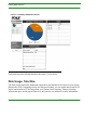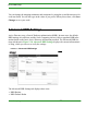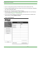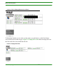
1
Scale Computing Storage
Cluster User Guide
Scale Computing
5225 Exploration Drive
Indianapolis, IN, 46241
Contents
Contents
CHAPTER 1
READ BEFORE YOU START - Important
Information About Your Cluster . . . . . . . . . . . . . . . . . xi
Obtaining Login Credentials for Your Cluster . . . . . . . . . . . . . . . . . . . . . . . . . . . xi
Register for a My Scale Account . . . . . . . . . . . . . . . . . . . . . . . . . . . . . . . . . . . xi
Complete and Return the Pre-Installation Questionnaire . . . . . . . . . . . . xiii
Obtain Password from Scale Computing Technical Support . . . . . . . . . xiii
Network as a Backplane for Your Cluster . . . . . . . . . . . . . . . . . . . . . . . . . . . . . xiii
Maintaining Cluster Availability . . . . . . . . . . . . . . . . . . . . . . . . . . . . . . . . . . . . . . . xv
Revision History . . . . . . . . . . . . . . . . . . . . . . . . . . . . . . . . . . . . . . . . . . . . . . . . . . . . xvi
CHAPTER 2
Introduction . . . . . . . . . . . . . . . . . . . . . . . . . . . . . . . . . . . . 1
Reducing Cost . . . . . . . . . . . . . . . . . . . . . . . . . . . . . . . . . . . . . . . . . . . . . . . . . . . . . . . 1
Unit Costs . . . . . . . . . . . . . . . . . . . . . . . . . . . . . . . . . . . . . . . . . . . . . . . . . . . . . . . . . 2
Scaling Costs. . . . . . . . . . . . . . . . . . . . . . . . . . . . . . . . . . . . . . . . . . . . . . . . . . . . . . 2
Silo Costs . . . . . . . . . . . . . . . . . . . . . . . . . . . . . . . . . . . . . . . . . . . . . . . . . . . . . . . . . 2
Increasing Control . . . . . . . . . . . . . . . . . . . . . . . . . . . . . . . . . . . . . . . . . . . . . . . . . . . . 2
Adding Convenience. . . . . . . . . . . . . . . . . . . . . . . . . . . . . . . . . . . . . . . . . . . . . . . . . . 3
Flexible . . . . . . . . . . . . . . . . . . . . . . . . . . . . . . . . . . . . . . . . . . . . . . . . . . . . . . . . . . . 3
Unified . . . . . . . . . . . . . . . . . . . . . . . . . . . . . . . . . . . . . . . . . . . . . . . . . . . . . . . . . . . . 3
Easy to Use . . . . . . . . . . . . . . . . . . . . . . . . . . . . . . . . . . . . . . . . . . . . . . . . . . . . . . . 3
Revision History . . . . . . . . . . . . . . . . . . . . . . . . . . . . . . . . . . . . . . . . . . . . . . . . . . . . . . 3
CHAPTER 3
Logging In. . . . . . . . . . . . . . . . . . . . . . . . . . . . . . . . . . . . . . 5
Troubleshooting Certificate Errors. . . . . . . . . . . . . . . . . . . . . . . . . . . . . . . . . . . . . . 7
Troubleshooting Certificate Errors in Firefox. . . . . . . . . . . . . . . . . . . . . . . . . . 7
Troubleshooting Certificate Errors in Internet Explorer . . . . . . . . . . . . . . . . 9
Remote Support Help . . . . . . . . . . . . . . . . . . . . . . . . . . . . . . . . . . . . . . . . . . . . . 11
Revision History . . . . . . . . . . . . . . . . . . . . . . . . . . . . . . . . . . . . . . . . . . . . . . . . . . . . . 13
Scale Computing
i
Contents
CHAPTER 4
Dashboards . . . . . . . . . . . . . . . . . . . . . . . . . . . . . . . . . . . 15
Summary Dashboard Screen . . . . . . . . . . . . . . . . . . . . . . . . . . . . . . . . . . . . . . . . . 15
Disk Usage: Total Size . . . . . . . . . . . . . . . . . . . . . . . . . . . . . . . . . . . . . . . . . . . . 16
Nodes . . . . . . . . . . . . . . . . . . . . . . . . . . . . . . . . . . . . . . . . . . . . . . . . . . . . . . . . . . . 17
Replication Status. . . . . . . . . . . . . . . . . . . . . . . . . . . . . . . . . . . . . . . . . . . . . . . . . 18
Node Status Screen . . . . . . . . . . . . . . . . . . . . . . . . . . . . . . . . . . . . . . . . . . . . . . . . . 18
IP Address and Node Status . . . . . . . . . . . . . . . . . . . . . . . . . . . . . . . . . . . . . . 20
SCM - Scale Computing Cluster Manager Indicator . . . . . . . . . . . . . 20
FS - File System Indicator . . . . . . . . . . . . . . . . . . . . . . . . . . . . . . . . 20
Drives . . . . . . . . . . . . . . . . . . . . . . . . . . . . . . . . . . . . . . . . . . . . . . . . 21
IPM - IP Manager Indicator. . . . . . . . . . . . . . . . . . . . . . . . . . . . . . . . 24
iSCSI. . . . . . . . . . . . . . . . . . . . . . . . . . . . . . . . . . . . . . . . . . . . . . . . . 25
NFS - Network File System Indicator . . . . . . . . . . . . . . . . . . . . . . . . 25
CIFS - Common Internet File System Indicator . . . . . . . . . . . . . . . . 25
Virtual IP Mapping. . . . . . . . . . . . . . . . . . . . . . . . . . . . . . . . . . . . . . . 25
Revision History . . . . . . . . . . . . . . . . . . . . . . . . . . . . . . . . . . . . . . . . . . . . . . . . . . . . . 25
CHAPTER 5
Configuration. . . . . . . . . . . . . . . . . . . . . . . . . . . . . . . . . . 27
Password . . . . . . . . . . . . . . . . . . . . . . . . . . . . . . . . . . . . . . . . . . . . . . . . . . . . . . . . . . . 27
DNS. . . . . . . . . . . . . . . . . . . . . . . . . . . . . . . . . . . . . . . . . . . . . . . . . . . . . . . . . . . . . . . . 29
Search Domains . . . . . . . . . . . . . . . . . . . . . . . . . . . . . . . . . . . . . . . . . . . . . . . . . . 30
DNS Servers . . . . . . . . . . . . . . . . . . . . . . . . . . . . . . . . . . . . . . . . . . . 31
Time Server . . . . . . . . . . . . . . . . . . . . . . . . . . . . . . . . . . . . . . . . . . . . . . . . . . . . . . 32
Virtual IPs . . . . . . . . . . . . . . . . . . . . . . . . . . . . . . . . . . . . . . . . . . . . . . . . . . . . . . . . 33
Active Directory . . . . . . . . . . . . . . . . . . . . . . . . . . . . . . . . . . . . . . . . . . . . . . . . . . . 34
Basic Settings . . . . . . . . . . . . . . . . . . . . . . . . . . . . . . . . . . . . . . . . . . . . . . . . . . . . 35
UID Mapping . . . . . . . . . . . . . . . . . . . . . . . . . . . . . . . . . . . . . . . . . . . 37
Advanced KRB Settings. . . . . . . . . . . . . . . . . . . . . . . . . . . . . . . . . . . . . . . . . . . . . . 38
Syslog Server Setup . . . . . . . . . . . . . . . . . . . . . . . . . . . . . . . . . . . . . . . . . . . . . . 39
Alerts . . . . . . . . . . . . . . . . . . . . . . . . . . . . . . . . . . . . . . . . . . . . . . . . . . . . . . . . . . . . 40
Revision History . . . . . . . . . . . . . . . . . . . . . . . . . . . . . . . . . . . . . . . . . . . . . . . . . . . . . 43
CHAPTER 6
iSCSI, CIFS, and NFS Management. . . . . . . . . . . . . 45
iSCSI Management . . . . . . . . . . . . . . . . . . . . . . . . . . . . . . . . . . . . . . . . . . . . . . . . . . 45
Scale Computing
ii
Contents
Targets (iSCSI Management) . . . . . . . . . . . . . . . . . . . . . . . . . . . . . . . . . . . . . . 46
Creating a New iSCSI Target . . . . . . . . . . . . . . . . . . . . . . . . . . . . . . 47
General Tab in Create iSCSI Target Dialog Box . . . . . . . . . . . . . . 48
CHAP Tab in Create iSCSI Target Dialog Box . . . . . . . . . . . . . . . . 49
Updating an Existing Target to an SPC-3 PR Compliance Enabled Target 51
Modifying an iSCSI Target . . . . . . . . . . . . . . . . . . . . . . . . . . . . . . . . 52
Deleting iSCSI Targets . . . . . . . . . . . . . . . . . . . . . . . . . . . . . . . . . . . 52
LUNs (iSCSI Management) . . . . . . . . . . . . . . . . . . . . . . . . . . . . . . . . . . . . . . . . 52
Creating an iSCSI Target LUN . . . . . . . . . . . . . . . . . . . . . . . . . . . . . 53
Modifying an iSCSI LUN . . . . . . . . . . . . . . . . . . . . . . . . . . . . . . . . . . 55
Deleting an iSCSI LUN . . . . . . . . . . . . . . . . . . . . . . . . . . . . . . . . . . . 55
Target Details. . . . . . . . . . . . . . . . . . . . . . . . . . . . . . . . . . . . . . . . . . . . . . . . . . . . . 55
iSCSI Initiators and the Scale Computing Cluster . . . . . . . . . . . . . . . . . . . . . . 56
Connecting iSCSI Initiators to a Scale Computing Cluster . . . . . . . . . . . . 56
Multipathing - General Requirements . . . . . . . . . . . . . . . . . . . . . . . . . . . . . . . 57
Best Practices for Multipathing . . . . . . . . . . . . . . . . . . . . . . . . . . . . . . . . . . . . . 57
Shares . . . . . . . . . . . . . . . . . . . . . . . . . . . . . . . . . . . . . . . . . . . . . . . . . . . . . . . . . . . . . 58
Creating and Configuring New Shares . . . . . . . . . . . . . . . . . . . . . . . . . . . . . . 59
Create a New Share 60
Creating a CIFS Share 61
Creating an NFS Share. . . . . . . . . . . . . . . . . . . . . . . . . . . . . . . . . . . . . . . . . . . . 63
Mounting and Tuning an NFS Share . . . . . . . . . . . . . . . . . . . . . . . . . . . . . . . . 64
Paths for Mounting an NFS Share 64
Mounting an NFS Share - Mac 65
Mounting an NFS Share - Windows 65
Setting Read and Write Block Sizes for NFS Shares . . . . . . . . . . . . 66
NFS Storage Space Reporting . . . . . . . . . . . . . . . . . . . . . . . . . . . . . 66
Modifying Shares . . . . . . . . . . . . . . . . . . . . . . . . . . . . . . . . . . . . . . . . . . . . . . . . . 66
Deleting a Share . . . . . . . . . . . . . . . . . . . . . . . . . . . . . . . . . . . . . . . . . . . . . . . . . . 67
Trash . . . . . . . . . . . . . . . . . . . . . . . . . . . . . . . . . . . . . . . . . . . . . . . . . . . . . . . . . . . . . . . 67
Revision History . . . . . . . . . . . . . . . . . . . . . . . . . . . . . . . . . . . . . . . . . . . . . . . . . . . . . 71
CHAPTER 7
Replication/Snapshot . . . . . . . . . . . . . . . . . . . . . . . . . . 73
Setup Outgoing Replication Schedule . . . . . . . . . . . . . . . . . . . . . . . . . . . . . . . . . 73
Navigate to the Outgoing Replication Schedule Screen . . . . . . . . . . . . . . 74
Scale Computing
iii
Contents
Manually Running a Replication . . . . . . . . . . . . . . . . . . . . . . . . . . . . . . . . . . . . 75
Adding a Scheduled Replication. . . . . . . . . . . . . . . . . . . . . . . . . . . . . . . . . . . . 75
Modifying a Scheduled Replication . . . . . . . . . . . . . . . . . . . . . . . . . . . . . . . . . 77
Deleting a Scheduled Replication . . . . . . . . . . . . . . . . . . . . . . . . . . . . . . . . . . 78
Outgoing Replication Log . . . . . . . . . . . . . . . . . . . . . . . . . . . . . . . . . . . . . . . . . . . . 79
Incoming Replication Log . . . . . . . . . . . . . . . . . . . . . . . . . . . . . . . . . . . . . . . . . . . . 80
Restoring a LUN/Share . . . . . . . . . . . . . . . . . . . . . . . . . . . . . . . . . . . . . . . . . . . . . . 81
Snapshots . . . . . . . . . . . . . . . . . . . . . . . . . . . . . . . . . . . . . . . . . . . . . . . . . . . . . . . . . . 84
Taking a Snapshot . . . . . . . . . . . . . . . . . . . . . . . . . . . . . . . . . . . . . . . . . . . . . . . . 85
Retaining and Releasing Snapshots . . . . . . . . . . . . . . . . . . . . . . . . . . . . . . . . 86
Deleting a Snapshot. . . . . . . . . . . . . . . . . . . . . . . . . . . . . . . . . . . . . . . . . . . . . . . 86
Revision History . . . . . . . . . . . . . . . . . . . . . . . . . . . . . . . . . . . . . . . . . . . . . . . . . . . . . 88
CHAPTER 8
Software Maintenance . . . . . . . . . . . . . . . . . . . . . . . . . 91
Remote Support . . . . . . . . . . . . . . . . . . . . . . . . . . . . . . . . . . . . . . . . . . . . . . . . . . . . . 91
Firmware Updates . . . . . . . . . . . . . . . . . . . . . . . . . . . . . . . . . . . . . . . . . . . . . . . . . . . 93
Down-time for Firmware Updates . . . . . . . . . . . . . . . . . . . . . . . . . . . . . . . . . . 94
How to Update Your Firmware . . . . . . . . . . . . . . . . . . . . . . . . . . . . . . . . . . . . . 94
Troubleshooting a Firmware Update . . . . . . . . . . . . . . . . . . . . . . . . . . . . . . . . 98
Update Fails or Terminates. . . . . . . . . . . . . . . . . . . . . . . . . . . . . . . . 98
Microsoft iSCSI Fails to Reconnect . . . . . . . . . . . . . . . . . . . . . . . . . 98
Updating From a Legacy Version (pre-2.1.4) . . . . . . . . . . . . . . . . . . 98
Update Hangs or Will Not Complete . . . . . . . . . . . . . . . . . . . . . . . . . 99
Shutting Down a Node or the Cluster. . . . . . . . . . . . . . . . . . . . . . . . . . . . . . . . . . 99
Problems Shutdown Can Cause . . . . . . . . . . . . . . . . . . . . . . . . . . . . . . . . . . . 99
How to Shutdown a Node or Your Cluster . . . . . . . . . . . . . . . . . . . . . . . . . . . 99
Register Your Cluster . . . . . . . . . . . . . . . . . . . . . . . . . . . . . . . . . . . . . . . . . . . . . . . 101
Revision History . . . . . . . . . . . . . . . . . . . . . . . . . . . . . . . . . . . . . . . . . . . . . . . . . . . . 102
CHAPTER 9
Hardware Maintenance . . . . . . . . . . . . . . . . . . . . . . . 105
Adding a Node . . . . . . . . . . . . . . . . . . . . . . . . . . . . . . . . . . . . . . . . . . . . . . . . . . . . . 105
When to Add a Node and What to Expect . . . . . . . . . . . . . . . . . . . . . . . . . . 106
Adding the Virtual IP for Your New Node. . . . . . . . . . . . . . . . . . . . . . . 106
Configuring the New Node . . . . . . . . . . . . . . . . . . . . . . . . . . . . . . . . . . . . . . . . 107
Scale Computing
iv
Contents
Adding Your New Node. . . . . . . . . . . . . . . . . . . . . . . . . . . . . . . . . . . . . . . . . . . 108
Adding or Removing a Drive. . . . . . . . . . . . . . . . . . . . . . . . . . . . . . . . . . . . . . . . . 109
How to Add or Remove a Drive . . . . . . . . . . . . . . . . . . . . . . . . . . . . . . . . . . . 110
What to Do If You Pulled the Wrong Drive. . . . . . . . . . . . . . . . . . . . . . . . . . 112
What to Do After Adding a Drive . . . . . . . . . . . . . . . . . . . . . . . . . . . . . . . . . . 113
How to Rebalance a Cluster . . . . . . . . . . . . . . . . . . . . . . . . . . . . . . . . . . . . . . . . . 113
Revision History . . . . . . . . . . . . . . . . . . . . . . . . . . . . . . . . . . . . . . . . . . . . . . . . . . . . 114
CHAPTER 10
Scale Computing
Contact Support . . . . . . . . . . . . . . . . . . . . . . . . . . . . . . 115
v
Contents
Scale Computing
vi
List of Figures
My Scale Login and Registration Screen . . . . . . . . . . . . . . . . . . . . . . . . . . . . . . . . . . . . . . . . . . . .
xii
Cluster Configuration for Regular Nodes . . . . . . . . . . . . . . . . . . . . . . . . . . . . . . . . . . . . . . . . . . . . xiv
Cluster Configuration for High Availability Nodes . . . . . . . . . . . . . . . . . . . . . . . . . . . . . . . . . . . . . xv
Logging in to the Scale Computing Cluster Manager . . . . . . . . . . . . . . . . . . . . . . . . . . . . . . . . . . . 6
Firefox Certificate Error . . . . . . . . . . . . . . . . . . . . . . . . . . . . . . . . . . . . . . . . . . . . . . . . . . . . . . . . . . 7
Firefox Add Certificate . . . . . . . . . . . . . . . . . . . . . . . . . . . . . . . . . . . . . . . . . . . . . . . . . . . . . . . . . . . . 8
Internet Explorer Certificate Error . . . . . . . . . . . . . . . . . . . . . . . . . . . . . . . . . . . . . . . . . . . . . . . . . . 9
Internet Explorer View Certificate . . . . . . . . . . . . . . . . . . . . . . . . . . . . . . . . . . . . . . . . . . . . . . . . . 10
Internet Explorer Certificate Wizard . . . . . . . . . . . . . . . . . . . . . . . . . . . . . . . . . . . . . . . . . . . . . . . . 11
Enter Your Credentials To Login Dialog Box . . . . . . . . . . . . . . . . . . . . . . . . . . . . . . . . . . . . . . . . . 12
Remote Support Dialog Box . . . . . . . . . . . . . . . . . . . . . . . . . . . . . . . . . . . . . . . . . . . . . . . . . . . . . 13
Summary Dashboard Screen. . . . . . . . . . . . . . . . . . . . . . . . . . . . . . . . . . . . . . . . . . . . . . . . . . . . . 16
Node Status Screen . . . . . . . . . . . . . . . . . . . . . . . . . . . . . . . . . . . . . . . . . . . . . . . . . . . . . . . . . . . . 19
Node Status Screen - Green Drive Icon . . . . . . . . . . . . . . . . . . . . . . . . . . . . . . . . . . . . . . . . . . . . 22
Node Status Screen - Yellow Drive Icon . . . . . . . . . . . . . . . . . . . . . . . . . . . . . . . . . . . . . . . . . . . . 23
Node Status Screen - Gray Drive Icon. . . . . . . . . . . . . . . . . . . . . . . . . . . . . . . . . . . . . . . . . . . . . . 24
Change Admin Password Panel . . . . . . . . . . . . . . . . . . . . . . . . . . . . . . . . . . . . . . . . . . . . . . . . . . 28
Attempting Password Change Across the Cluster . . . . . . . . . . . . . . . . . . . . . . . . . . . . . . . . . . . . . 29
Adding a Search Domain . . . . . . . . . . . . . . . . . . . . . . . . . . . . . . . . . . . . . . . . . . . . . . . . . . . . . . . . 30
Adding a DNS Server Domain . . . . . . . . . . . . . . . . . . . . . . . . . . . . . . . . . . . . . . . . . . . . . . . . . . . . 31
Time Server Configuration . . . . . . . . . . . . . . . . . . . . . . . . . . . . . . . . . . . . . . . . . . . . . . . . . . . . . . . 32
Virtual IP Configuration . . . . . . . . . . . . . . . . . . . . . . . . . . . . . . . . . . . . . . . . . . . . . . . . . . . . . . . . . 34
Basic Active Directory Configuration . . . . . . . . . . . . . . . . . . . . . . . . . . . . . . . . . . . . . . . . . . . . . . . 36
ADS is Working Dialog Box . . . . . . . . . . . . . . . . . . . . . . . . . . . . . . . . . . . . . . . . . . . . . . . . . . . . . . 36
UID Mapping Tab . . . . . . . . . . . . . . . . . . . . . . . . . . . . . . . . . . . . . . . . . . . . . . . . . . . . . . . . . . . . . . 37
Advanced KRB Settings. . . . . . . . . . . . . . . . . . . . . . . . . . . . . . . . . . . . . . . . . . . . . . . . . . . . . . . . . 38
Syslog Server Setup . . . . . . . . . . . . . . . . . . . . . . . . . . . . . . . . . . . . . . . . . . . . . . . . . . . . . . . . . . . 40
Alert Settings . . . . . . . . . . . . . . . . . . . . . . . . . . . . . . . . . . . . . . . . . . . . . . . . . . . . . . . . . . . . . . . . . 41
iSCSI Management Screen . . . . . . . . . . . . . . . . . . . . . . . . . . . . . . . . . . . . . . . . . . . . . . . . . . . . . . 46
Create an iSCSI Target Dialog Box . . . . . . . . . . . . . . . . . . . . . . . . . . . . . . . . . . . . . . . . . . . . . . . . 48
CHAP Configuration for a New iSCSI Target. . . . . . . . . . . . . . . . . . . . . . . . . . . . . . . . . . . . . . . . . 50
Scale Computing
vii
Adding CHAP Credentials to an iSCSI Target . . . . . . . . . . . . . . . . . . . . . . . . . . . . . . . . . . . . . . . . 51
Create iSCSI LUN Dialog Box . . . . . . . . . . . . . . . . . . . . . . . . . . . . . . . . . . . . . . . . . . . . . . . . . . . . 54
Shares . . . . . . . . . . . . . . . . . . . . . . . . . . . . . . . . . . . . . . . . . . . . . . . . . . . . . . . . . . . . . . . . . . . . . . 59
Creating a New Share . . . . . . . . . . . . . . . . . . . . . . . . . . . . . . . . . . . . . . . . . . . . . . . . . . . . . . . . . . 60
CIFS Share Level Permissions Table . . . . . . . . . . . . . . . . . . . . . . . . . . . . . . . . . . . . . . . . . . . . . . 62
NFS Host Access List Table . . . . . . . . . . . . . . . . . . . . . . . . . . . . . . . . . . . . . . . . . . . . . . . . . . . . . . 64
Confirm Delete . . . . . . . . . . . . . . . . . . . . . . . . . . . . . . . . . . . . . . . . . . . . . . . . . . . . . . . . . . . . . . . . 67
Trash . . . . . . . . . . . . . . . . . . . . . . . . . . . . . . . . . . . . . . . . . . . . . . . . . . . . . . . . . . . . . . . . . . . . . . . 68
Restoring a LUN . . . . . . . . . . . . . . . . . . . . . . . . . . . . . . . . . . . . . . . . . . . . . . . . . . . . . . . . . . . . . . 69
Restoring a Share . . . . . . . . . . . . . . . . . . . . . . . . . . . . . . . . . . . . . . . . . . . . . . . . . . . . . . . . . . . . . 70
Outgoing Replication Setup . . . . . . . . . . . . . . . . . . . . . . . . . . . . . . . . . . . . . . . . . . . . . . . . . . . . . . 74
Add Replication Schedule Dialog Box . . . . . . . . . . . . . . . . . . . . . . . . . . . . . . . . . . . . . . . . . . . . . . 76
Modify a Scheduled Replication Dialog Box . . . . . . . . . . . . . . . . . . . . . . . . . . . . . . . . . . . . . . . . . 78
Outgoing Replication Log. . . . . . . . . . . . . . . . . . . . . . . . . . . . . . . . . . . . . . . . . . . . . . . . . . . . . . . . 79
Incoming Replication Log. . . . . . . . . . . . . . . . . . . . . . . . . . . . . . . . . . . . . . . . . . . . . . . . . . . . . . . . 80
Restore To Local . . . . . . . . . . . . . . . . . . . . . . . . . . . . . . . . . . . . . . . . . . . . . . . . . . . . . . . . . . . . . . 81
Restore LUN Dialog Box . . . . . . . . . . . . . . . . . . . . . . . . . . . . . . . . . . . . . . . . . . . . . . . . . . . . . . . . 82
Restore Share Dialog Box . . . . . . . . . . . . . . . . . . . . . . . . . . . . . . . . . . . . . . . . . . . . . . . . . . . . . . . 83
Snapshots . . . . . . . . . . . . . . . . . . . . . . . . . . . . . . . . . . . . . . . . . . . . . . . . . . . . . . . . . . . . . . . . . . . 85
Reaching Snapshot Maximum . . . . . . . . . . . . . . . . . . . . . . . . . . . . . . . . . . . . . . . . . . . . . . . . . . . . 86
Delete Confirmation Dialog Box . . . . . . . . . . . . . . . . . . . . . . . . . . . . . . . . . . . . . . . . . . . . . . . . . . . 87
A Snapshot Marked for Deletion . . . . . . . . . . . . . . . . . . . . . . . . . . . . . . . . . . . . . . . . . . . . . . . . . . 87
Trying to Delete a Retained Snapshot . . . . . . . . . . . . . . . . . . . . . . . . . . . . . . . . . . . . . . . . . . . . . . 88
Remote Support . . . . . . . . . . . . . . . . . . . . . . . . . . . . . . . . . . . . . . . . . . . . . . . . . . . . . . . . . . . . . . . 92
Inactive Enable Remote Support Button . . . . . . . . . . . . . . . . . . . . . . . . . . . . . . . . . . . . . . . . . . . . . 93
Checking for Updates . . . . . . . . . . . . . . . . . . . . . . . . . . . . . . . . . . . . . . . . . . . . . . . . . . . . . . . . . . 95
Firmware Update Screen . . . . . . . . . . . . . . . . . . . . . . . . . . . . . . . . . . . . . . . . . . . . . . . . . . . . . . . . 96
Confirm Update Dialog Box . . . . . . . . . . . . . . . . . . . . . . . . . . . . . . . . . . . . . . . . . . . . . . . . . . . . . . 97
Updating the Firmware Across the Cluster Windows. . . . . . . . . . . . . . . . . . . . . . . . . . . . . . . . . . . 97
Node Shutdown . . . . . . . . . . . . . . . . . . . . . . . . . . . . . . . . . . . . . . . . . . . . . . . . . . . . . . . . . . . . . . 100
Register Your Cluster. . . . . . . . . . . . . . . . . . . . . . . . . . . . . . . . . . . . . . . . . . . . . . . . . . . . . . . . . . 102
Configure New Node . . . . . . . . . . . . . . . . . . . . . . . . . . . . . . . . . . . . . . . . . . . . . . . . . . . . . . . . . . 107
Node Configuration Screen . . . . . . . . . . . . . . . . . . . . . . . . . . . . . . . . . . . . . . . . . . . . . . . . . . . . . 108
Scale Computing
viii
Add This Node to Cluster . . . . . . . . . . . . . . . . . . . . . . . . . . . . . . . . . . . . . . . . . . . . . . . . . . . . . . . 109
Drive is Being Removed or Is Down . . . . . . . . . . . . . . . . . . . . . . . . . . . . . . . . . . . . . . . . . . . . . . 111
Empty Drive Slot . . . . . . . . . . . . . . . . . . . . . . . . . . . . . . . . . . . . . . . . . . . . . . . . . . . . . . . . . . . . . 111
Add a Drive Message. . . . . . . . . . . . . . . . . . . . . . . . . . . . . . . . . . . . . . . . . . . . . . . . . . . . . . . . . . 112
Re-Adding a Drive . . . . . . . . . . . . . . . . . . . . . . . . . . . . . . . . . . . . . . . . . . . . . . . . . . . . . . . . . . . . 113
Scale Computing
ix
Scale Computing
x
Obtaining Login Credentials for Your Cluster
CHAPTER 1
READ BEFORE YOU
START - Important
Information About
Your Cluster
This chapter outlines important concepts to keep in mind when configuring and managing
your cluster. The concepts are discussed in the following sections:
• Obtaining Login Credentials for Your Cluster
• Network as a Backplane for Your Cluster
• Maintaining Cluster Availability
Obtaining Login Credentials for Your Cluster
How to obtain login credentials for your cluster is described in the following sections:
• Register for a My Scale Account
• Complete and Return the Pre-Installation Questionnaire
• Obtain Password from Scale Computing Technical Support
Register for a My Scale Account
To register for a My Scale account, take the following steps:
1
Open a web browser and navigate to www.scalecomputing.com.
Scale Computing
xi
Obtaining Login Credentials for Your Cluster
2
Click the My Scale Login button in the upper right corner of the screen.The My Scale
Login and Registration screen appears as shown in Figure 1-1, My Scale Login and Registration Screen.
FIGURE 1-1.
3
4
5
6
7
My Scale Login and Registration Screen
Select I’m new.
Enter your email address in the Email address field.
Enter a password in the Choose a password field.
(Optional) Turn on the Auto-login on future visits checkbox.
Click Register.
You now have a My Scale account. The account entitles you to exclusive guides, white papers
and other types of documentation that will help you get the most out of your Scale Computing
cluster.
Scale Computing
xii
Network as a Backplane for Your Cluster
Complete and Return the Pre-Installation Questionnaire
Before you can obtain login credentials from Scale Computing Technical Support, which are
required to complete installation, you must complete the Pre-Installation Questionnaire (PIQ)
and return it to Scale Computing. To fill it out, do the following:
1
2
3
4
Open the web browser of your choice and navigate to:
http://www.scalecomputing.com.
Run a search for “Pre-installation Questionnaire” using the search box in the upper right
corner of the Scale Computing website. The PIQ will come back in the list of search
results.
For the returned PIQ in the search results, click Download Now.
Complete the PIQ and return it to [email protected].
Obtain Password from Scale Computing Technical Support
When Scale Computing Technical Support receives your PIQ, they will contact you and provide you with login credentials. If you have requisitioned for Scale Computing Technical Support to provide remote or on-site installation services, they will schedule you for your
installation.
For more information about how to contact Scale Computing Technical Support, refer to
Chapter 10, Contact Support.
Network as a Backplane for Your Cluster
The Scale Computing cluster uses a private subnetwork as a backplane to connect nodes to
one another. This subnetwork is only accessible by nodes in your cluster and enables them to
communicate their status to one another and perform data striping and mirroring across your
cluster. To ensure proper functionality of your cluster, the selected IPs for this subnetwork
should be composed of IP addresses that do not overlap with any others within your company.
Scale Computing
xiii
Network as a Backplane for Your Cluster
NOTE: The IP addresses you select are PERMANENT. You will not be able to change them once you set them.
Careful planning prior to choosing these addresses is recommended.
When connecting a node to your cluster, use the port(s) labelled Backplane to construct the
private subnetwork that acts as your cluster’s backplane. Use the port(s) labelled LAN to connect your cluster to the rest of your company’s network.
Configuration for a cluster composed of regular nodes (a regular node has one Backplane
port and one LAN port) would look like the example cluster shown in Figure 1-2, Cluster
Configuration for Regular Nodes.
FIGURE 1-2.
Cluster Configuration for Regular Nodes
Configuration for a cluster composed of high availability (HA) nodes (HA nodes have two
Backplane ports and two LAN ports) would look like the example cluster shown in Figure 13, Cluster Configuration for High Availability Nodes.
Scale Computing
xiv
Maintaining Cluster Availability
FIGURE 1-3.
Cluster Configuration for High Availability Nodes
In each configuration example, the network used to form the backplane for your cluster is kept
completely separate from the rest of your network. This concept is key to configuring an
effective, functional cluster.
Maintaining Cluster Availability
Your Scale Computing cluster can continue operation without issue if you have drive failure
on a single node. However, if drives fail on more than one node, your cluster’s file system
unmounts in order to protect your data from corruption.
You can help ensure cluster availability by doing the following:
Scale Computing
xv
Revision History
• Responding immediately if a node indicates a drive is down.
• Avoiding disconnecting nodes from the private network acting as your cluster’s backplane.
• Ensuring all cables are securely plugged in for all nodes in your cluster.
It is not recommended that you move nodes around your cluster by unplugging them from the
backplane and then plugging them in again. If you determine that you must move nodes by
unplugging them from the backplane, be aware that you must plug in the node and wait for it
to be listed as healthy and available before moving any other nodes. If a drive fails on another
node while the node you plugged back in is coming up, the file system unmounts.
Revision History
This section contains information describing how this chapter has been revised.
Release 2.4:
• Re-added chapter to the User Guide.
Release 2.3.1:
• Updated the introduction at the start of the READ BEFORE YOU START - Important
Information About Your Cluster chapter.
• Added the Revision History section.
Scale Computing
xvi
Reducing Cost
CHAPTER 2
Introduction
Welcome to the Scale Computing Storage Cluster User Guide.
Before logging into your Scale Computing cluster, make sure you have read and reviewed the
following documentation:
• Scale Computing Storage Cluster Installation Guide
• Concepts and Planning Guide for the Scale Computing Storage Cluster
The Scale Computing Storage Cluster Installation Guide provides detailed information
about how to correctly install and configure your cluster. The Concepts and Planning Guide
for the Scale Computing Storage Cluster describes how a Scale Computing cluster differs
from other storage systems and provides information about what you need to think about prior
to installing a cluster.
The rest of this chapter details the ways in which the Scale Computing cluster reduces costs,
increases control, and adds convenience to planning and managing your storage. These concepts are discussed in the following sections:
• Reducing Cost
• Increasing Control
• Adding Convenience
Reducing Cost
Scale Computing is able to reduce cost in several key areas:
• Unit Costs
• Scaling Costs
• Silo Costs
Scale Computing
1
Increasing Control
Unit Costs
The nodes in a Scale Computing cluster are created using off-the-shelf hardware and Scale
Computing’s own Intelligent Clustered Operating System (ICOSTM) software. The combination of off-the-shelf parts and Scale Computing’s powerful software enables Scale Computing
to reduce entry prices by 75% when compared to other vendors of storage solutions.
Scaling Costs
Each node in a Scale Computing cluster contains Scale Computing’s ICOS software, enabling
you to increase your storage capacity and performance simply by stacking nodes on top of
each other. You can buy additional storage as you need it.
Silo Costs
ICOS technology’s Protocol Abstraction Layer (PAL) makes protocols virtually irrelevant.
Currently, PAL reads CIFS, NFS, and iSCSI protocols simultaneously. PAL makes it possible
to mix and match protocols in the same cluster without having to scrap your investment in
storage every time a new protocol is introduced. Instead, you would simply buy another storage node with the new protocol on it and the entire cluster - including the old units - would be
able to run all the protocols. This enables you to future-proof your storage investment and
keep costs down.
Increasing Control
The Scale Computing cluster is easy to expand and offers an extremely flexible architecture.
You can mix and match node densities as you need. The fine-grain scalability of Scale Computing clusters allows you to scale by as little as 1TB. Adding capacity to your Scale Computing cluster is as simple as adding an additional node to your existing cluster while it is live and
still running services. Data is automatically striped and mirrored across all nodes when you do
this.
Scale Computing
2
Adding Convenience
Adding Convenience
Scale Computing’s ICOS is designed to minimize the management time and stress associated
with storage by being:
• Flexible
• Unified
• Easy to Use
Flexible
Scale Computing’s ICOS offers flexible scalability that eliminates the time spent on capacity
planning by 90% or more - just add an additional node when you need more storage. Provisioning is also simple; choose from an easy-to-use GUI or command lines.
Unified
Scale Computing clusters include file and block-level protocols, allowing SAN/NAS environments to run from each storage node. CIFS, NFS, and iSCSI all run simultaneously. This
allows you to eliminate file servers, consolidating onto a single, easily scalable platform.
Easy to Use
Scale Computing clusters do not require command-line management. With a streamlined
interface, training takes less than half a day. Some of the most common tasks, such as creating
a LUN, take less than a minute to complete with ICOS 2.0. The entire cluster can be managed
remotely, from any web browser - no client software or agents needed.
Revision History
This section contains information describing how this chapter has been revised.
Scale Computing
3
Revision History
Release 2.4:
• Minor edits.
• Changed ICS to ICOS and added trademarking.
Release 2.3.3:
• Added material to the introduction.
Release 2.3.1:
• Added text to introductory material at the start of the Introduction chapter.
• Added sections Reducing Cost, Increasing Control, and Adding Convenience.
• Added the Revision History section.
Scale Computing
4
CHAPTER 3
Logging In
The Scale Computing cluster is unique in that you can use a GUI interface to remotely manage all aspects of the cluster, using a simple web browser. You can log in and manage your
cluster from any node, just type the address for the selected node into your browser’s address
window to get started.
If this is your first time logging in to your Scale Computing cluster, you will need to fill out
the Pre-Installation Questionnaire (PIQ) and obtain login credentials from Scale Computing
Technical Support. For details about how to do this, refer to Chapter 1, READ BEFORE
YOU START - Important Information About Your Cluster. You can log in to your cluster
by pointing your web browser of choice at any of the individual nodes using the configuration
information from your initial setup as detailed in the Scale Computing Storage Cluster
Installation Guide.
The address you enter into your browser may be an IP address, hostname, or round-robin DNS
entry. For example, if you have all the nodes in your cluster assigned to the DNS entry cluster.example.com, you can point your browser at https://cluster.example.com. In the case of a
node failure, the IP address assigned to that node moves to an active node in the cluster. The
login dialog box is shown in Figure 3-1, Logging in to the Scale Computing Cluster Manager.
NOTE: Be sure to use the HTTPS protocol when connecting to the web-based Scale Computing Cluster Manager.
Scale Computing
5
FIGURE 3-1.
Logging in to the Scale Computing Cluster Manager
The username for the administrator account is admin. You cannot change the name of the
admin account. Enter the password you obtained from Scale Computing Technical Support.
The first time you log into the Scale Computing Cluster Manager, you are presented with a
registration dialog box (See Chapter 8, Software Maintenance). You can log out of the
Scale Computing Cluster Manager by clicking Logout at the bottom of the main menu located
on the left side of the Scale Computing Cluster Manager.
The Scale Cluster Manager uses Adobe Flash. You may need to install this plugin prior to
working with the Scale Cluster Manager. The HTTPS protocol requires you to accept a security certificate before connecting. If it has not been accepted, the following error occurs:
Login Error - Could not reach UI server. This error is most likely due to your browser
rejecting the secure certificate installed on the cluster nodes. For more information about certificate errors, refer to section Troubleshooting Certificate Errors.
Scale Computing
6
Troubleshooting Certificate Errors
Troubleshooting Certificate Errors
When connecting to the cluster for the first time or trying to log in, your browser may complain about the secure certificate for the web interface. The error relates to the fact that the certificate is self-signed, and configured for the localhost domain name. You can safely choose to
continue to the site. Most browsers allow you to permanently add the certificate to a list of
approved certificates. However, sometimes the error is more involved. The following sections
provide troubleshooting techniques:
• Troubleshooting Certificate Errors in Firefox
• Troubleshooting Certificate Errors in Internet Explorer
Troubleshooting Certificate Errors in Firefox
When using Firefox, the browser presents an error page when visiting a site with a self-signed
certificate or invalid domain name, as shown in Figure 3-2, Firefox Certificate Error.
FIGURE 3-2.
Firefox Certificate Error
Take the following steps to fix this issue:
Scale Computing
7
Troubleshooting Certificate Errors
1
2
3
Click the link at the bottom of the dialog box that says Or you can add an exception... .
This expands into a dialog box with more information and two buttons: Get me out of
here! and Add Exception....
Click Add Exception.... A dialog box appears.
In the top right of the dialog box, click Get Certificate. This populates the Certificate Status section of the dialog box, as shown in Figure 3-3, Firefox Add Certificate.
FIGURE 3-3.
4
Firefox Add Certificate
At the bottom of the dialog box, click Confirm Security Exception.
Scale Computing
8
Troubleshooting Certificate Errors
Troubleshooting Certificate Errors in Internet Explorer
When using Internet Explorer, the browser presents an error page reporting a problem with the
website's security certificate as shown in Figure 3-4, Internet Explorer Certificate Error.
FIGURE 3-4.
Internet Explorer Certificate Error
To fix this issue, take the following steps:
1
2
3
Click Continue to this website (not recommended) to temporarily accept the certificate
for this browser session.
Click Certificate Error in the address bar.
Click View Certificates.
Scale Computing
9
Troubleshooting Certificate Errors
FIGURE 3-5.
4
5
6
7
Internet Explorer View Certificate
In the Certificate dialog box, click Install Certificate as shown in Figure 3-5, Internet
Explorer View Certificate. This pops up the Certificate Import Wizard, as shown in
Figure 3-6, Internet Explorer Certificate Wizard.
In the Certificate Import Wizard click Next.
Select Place all certificates in the following store and click Browse.
Select Trusted Root Certification Authorities and click OK.
Scale Computing
10
Troubleshooting Certificate Errors
FIGURE 3-6.
8
9
Internet Explorer Certificate Wizard
Click Next and then Finish.
If a security message pops up, choose Yes.
You should now be able to log into the site without generating the certificate error.
Remote Support Help
If for some reason you are unable to login to your cluster, you can initiate a remote support
session from the Enter Your Credentials To Login dialog box by clicking Help! as shown in
Figure 3-7, Enter Your Credentials To Login Dialog Box.
Scale Computing
11
Troubleshooting Certificate Errors
FIGURE 3-7.
Enter Your Credentials To Login Dialog Box
When you click Help!, the Remote Support dialog box appears as shown in Figure 3-8,
Remote Support Dialog Box.
Scale Computing
12
Revision History
FIGURE 3-8.
Remote Support Dialog Box
Call Scale Computing at +1-877-SCALE-59 (877-722-5359) and Technical Support will give
you a remote support code number you can enter, which allows Technical Support to diagnose
the problem remotely.
Revision History
This section contains information describing how this chapter has been revised.
Release 2.4:
• Removed password information.
• Changed all instances of Scale to Scale Computing.
• Updated the introduction to discuss the Pre-Installation Questionnaire.
Release 2.3.3:
Scale Computing
13
Revision History
• No change.
Release 2.3.1:
• Added text to introductory material at the start of the Logging In chapter.
• Added the Revision History section.
Scale Computing
14
Summary Dashboard Screen
CHAPTER 4
Dashboards
The Dashboards menu offers graphical, at-a-glance representations of the status of your cluster. You can quickly determine how much space is left on your cluster, whether replications
are in progress or have completed, and the status of your cluster’s nodes. The Scale Computing cluster graphically maps drives in each node to the physical configuration of your nodes,
so you can easily see which drive is having an issue.
This chapter discusses the features in the screens contained in the Dashboards menu in two
sections:
• Summary Dashboard Screen
• Node Status Screen
Summary Dashboard Screen
When you log into the Scale Computing Cluster Manager, you are presented with the Summary Dashboard screen. This screen includes information about the health of your individual
cluster nodes, overall storage usage, as well as any current incoming or outgoing replications.
This information is organized into three panels, discussed in the following sections:
• Disk Usage: Total Size
• Nodes
• Replication Status
The panels are shown in Figure 4-1, Summary Dashboard Screen.
Scale Computing
15
Summary Dashboard Screen
FIGURE 4-1.
Summary Dashboard Screen
Each panel provides information about the status of your cluster.
Disk Usage: Total Size
The Disk Usage panel in the dashboard reports the actual amount of free space on your cluster.
Because the Scale Computing cluster uses thin provisioning, you can create shares and iSCSI
logical unit numbers (LUNs) larger than your current cluster capacity. Thin provisioning
ensures that space on the physical drives is only used as it is needed. For more information
Scale Computing
16
Summary Dashboard Screen
about thin provisioning, see the Thin Provisioning chapter in the Concepts and Planning
Guide for the Scale Computing Storage Cluster.
As storage on your cluster is consumed, alerts are triggered at pre-set levels well in advance of
the cluster becoming full. See Chapter 5, Section Alerts for more information about configuring alerts.
Nodes
The Nodes panel displays the status for each node in your cluster. Status may be one of the
following:
• Up - The normal operating state of a Scale Computing cluster node.
• Down - The node is powered off or the cluster management service is unavailable. If the
dashboard shows a node in this state, but the node is not powered down, call Scale Computing Technical Support to diagnose the node.
• Going Out Of Service/Out Of Service - The node is about to perform an upgrade or is
currently being upgraded.
• Coming Up - This is a transitional state when the node changes from the Down state to
either Up or Unhealthy.
• Unhealthy - This is an indication that one or more services on a node are not fully operational. In most cases, a node recovers from an unhealthy state on its own within one to two
hours maximum. If a node does not appear able to recover, verify that there is nothing
physically wrong with the node, for example an unplugged network cable or unplugged
power. If a node remains unhealthy, call Scale Computing Technical Support for help in
diagnosing the issue.
NOTE: If more than one node is down, the filesystem unmounts to protect your data. If more than one node has a
drive failure at the same time, the filesystem also unmounts to protect your data.
For more information about how nodes affect cluster availability, refer to Chapter 1, READ
BEFORE YOU START - Important Information About Your Cluster.
Scale Computing
17
Node Status Screen
Replication Status
The Replication Status panel shows any current replication activity on the cluster. Active
Incoming Replications shows any replication tasks or jobs your cluster is working on to back
up other clusters. Active Outgoing Replications shows any replication tasks or jobs other clusters are working on to back up your cluster.
If there are no replications being processed, the panel displays None. If there are replications
being processed, information about each replication is displayed in two columns, Source
Cluster, and Status. The Source Cluster column shows the name of the cluster that contains the
data being replicated. If you did not provide a name for the cluster, then the ID number for the
cluster is displayed instead. The Status column shows how much of a replication job is complete as a percentage.
Node Status Screen
The Node Status screen provides status information for each node in the cluster. In the main
menu on the left side of the screen, click Dashboards. A menu expands beneath Dashboards
with two choices. Select the second thumbnail under Dashboards to view the Node Status
screen.
Each node on the Node Status screen is represented by a light grey panel. Figure 4-2, Node
Status Screen displays status information for three nodes in a cluster.
Scale Computing
18
Node Status Screen
FIGURE 4-2.
Node Status Screen
The information displayed for each node is discussed in the following sections:
• IP Address and Node Status
• SCM - Scale Computing Cluster Manager Indicator
• FS - File System Indicator
• Drives
• IPM - IP Manager Indicator
• iSCSI
• NFS - Network File System Indicator
• CIFS - Common Internet File System Indicator
• Virtual IP Mapping
Scale Computing
19
Node Status Screen
IP Address and Node Status
LAN IP Address and Node Status are located in the upper lefthand corner of each node. This
LAN IP address is the address used by iSCSI initiators when connecting to the cluster. For
more information about how Scale Computing clusters use LAN and Backplane IP addresses,
refer to Chapter 1, READ BEFORE YOU START - Important Information About Your
Cluster. For more information about how to setup iSCSI connections to the cluster, Chapter
6, Section iSCSI Initiators and the Scale Computing Cluster.
The current status of the node is also displayed. As with the node status information displayed
on the Summary Dashboard screen, the node may have a status of:
• Up
• Down
• Going Out of Service
• Coming Up
• Unhealthy
For more details about these status options refer to section Nodes.
SCM - Scale Computing Cluster Manager Indicator
Directly under each node's IP address and status is SCM - the Scale Computing Cluster Manager Indicator. This component is responsible for managing an individual node's configuration
and provides status and health information to other nodes in the cluster. A green light indicates
normal operation, and that all the services are up and running. The SCM indicator turns yellow if there are any issues with a node. The most common reason the SCM indicator turns yellow is that one of the nodes is not hosting a virtual IP though it should be (not applicable for
iSCSI-only implementations). If the node remains yellow even after checking your network's
health and correcting any issues you find, contact Scale Computing Technical Support.
FS - File System Indicator
Scale Computing
20
Node Status Screen
The File System indicator (FS) represents the status of the low-level Scale Computing cluster
filesystem. Green indicates normal working status. Yellow indicates the filesystem is in a
recovery state.
Drives
Drives is the hard drive indicator. The UI graphically represents the physical drives in each
node. The indicators on the UI correspond to the drive position on that node in your cluster,
making it easier to determine the location of the problem. For example the leftmost drive indicator maps to the leftmost drive on the node.
Each drive's status is represented with one of the following colors:
Green - The drive is healthy. If you click on the icon representing the drive, you get a message
saying the drive is up and serving data. The serial number for the drive is also listed. Figure 43, Node Status Screen - Green Drive Icon shows the message you get when you click a
green drive icon.
Scale Computing
21
Node Status Screen
FIGURE 4-3.
Node Status Screen - Green Drive Icon
Yellow - The drive is being restarted or removed from the system. If you click on a drive icon
in this state, you get a message saying that the drive is being restarted or removed from the
system. Figure 4-4, Node Status Screen - Yellow Drive Icon shows the message you get
when you click a yellow drive icon.
Scale Computing
22
Node Status Screen
FIGURE 4-4.
Node Status Screen - Yellow Drive Icon
Gray - The drive slot is empty, or the drive in that slot is fully disconnected from the system.
If you click on a drive icon with this status, you get a message stating that the drive is empty
and that you can add a new one in this slot. Figure 4-5, Node Status Screen - Gray Drive
Icon shows the message you get when you click a gray drive icon.
Scale Computing
23
Node Status Screen
FIGURE 4-5.
Node Status Screen - Gray Drive Icon
Red - This indicates that the system was unable to recover the drive. The system is still
mounted and serving data, however it is important to call Scale Computing Technical Support
immediately to diagnose the problem with the node. If another drive fails in a different node,
the system unmounts in order to protect your data from corruption.
For more information about adding and removing drives from the system, refer to Chapter 9,
Section Adding or Removing a Drive.
IPM - IP Manager Indicator
Located directly to the right of the LAN IP address and status of the node, is the IP manager
indicator (IPM). Green indicates normal operation. Yellow indicates the IP Manager compo-
Scale Computing
24
Revision History
nent is unhealthy on this node, and may not be participating in IP hosting for NFS and CIFS
shares.
iSCSI
The iSCSI Target indicator (iSCSI) is displayed to the right of the IPM. It shows whether the
iSCSI server component is operating properly. Green indicates normal operation. Yellow indicates the iSCSI target component is unhealthy on this node.
NFS - Network File System Indicator
The NFS indicator (NFS) is in the second row of each node, directly below IPM. The NFS
indicator displays whether the NFS component is operating properly. Green indicates normal
operation. Yellow indicates the NFS component is unhealthy on this node.
CIFS - Common Internet File System Indicator
The CIFS indicator (CIFS) is in the second row of each node just after NFS. It shows whether
the CIFS (also known as SMB) component is operating properly. Green indicates normal
operation. Yellow indicates the CIFS component is unhealthy on this node.
Virtual IP Mapping
On the righthand side of each grey panel representing a node is a white field (Virtual IP Mapping) populated with the virtual IP addresses each node is presently serving. These are the IP
addresses associated with CIFS and NFS shares. For more information about how to setup
CIFS and NFS connections to the cluster, refer to Chapter 6, Section Shares.
Revision History
This section contains information describing how this chapter has been revised.
Scale Computing
25
Revision History
Release 2.4:
• Minor edits.
Release 2.3.3:
• No change.
Release 2.3.1:
• Added text to introductory material at the start of the Dashboards chapter.
• Added the Revision History section.
Scale Computing
26
Password
CHAPTER 5
Configuration
The Configuration menu simplifies cluster configuration tasks that can often take hours to
accomplish. With a streamlined interface and well organized groups of information, you can
efficiently set passwords and configure the DNS server, time server, virtual IP addresses,
active directory, syslog, and alerts management settings.
You can find the Configuration menu by going to the main menu displayed on the left side of
the Scale Computing Cluster Manager and clicking Configuration. A menu expands beneath
Configuration. This chapter covers each choice on the menu in the following sections:
• Password
• DNS
• Time Server
• Virtual IPs
• Active Directory
• Syslog Server Setup
• Alerts
Password
To get to the Password screen, on the main menu on the left side of the Scale Computing Cluster Manager click Configuration. A sub menu appears with a list of choices. Click Password.
The Password screen appears and displays the Change Admin Password panel.
The Change Admin Password panel allows you to change the admin password for the entire
cluster. Enter the old (current) password, as well as the new password, and verification of the
new password. Click Save Changes to commit the new password to the entire cluster as
shown in Figure 5-1, Change Admin Password Panel.
Scale Computing
27
Password
FIGURE 5-1.
Change Admin Password Panel
NOTE: Your password must be at least four characters long, or you will not be able to submit your password
update.
When you submit changes to the cluster, the Scale Computing Cluster Manager commits the
changes to the configuration repository, validates the changes, and distributes the changes to
all nodes in the cluster in a transactionally safe manner. The procedure guarantees that the
cluster updates configurations on all nodes, and does not leave the cluster in a misconfigured
state should a failure occur. The Change Admin Password panel displays the status and success or failure of the procedure while it is running as shown in Figure 5-2, Attempting Password Change Across the Cluster.
Scale Computing
28
DNS
FIGURE 5-2.
Attempting Password Change Across the Cluster
If the password is changed successfully, the Change Admin Password panel displays the message Success at the bottom of the screen.
NOTE: The configuration manager does not allow changes to be made to the cluster unless all nodes are online.
DNS
Use the DNS screen to access and manage the DNS server settings. To reach the DNS screen,
on the main menu on the left side of the Scale Computing Cluster Manager click Configuration. A menu expands under DNS with a list of choices. Click DNS. The DNS screen appears
and displays the DNS Management panel, which is split into the Search Domains field and the
DNS Servers field. These will be discussed in the following sections:
• Search Domains
• DNS Servers
Scale Computing
29
DNS
Search Domains
If you are planning on using virtual IPs, the Scale Computing Cluster Manager requires that
you provide a search domain entry. Use the Search Domains field to enter or remove this
information as necessary. Setting up search domains allows you to specify just the hostname
for targets and permissions when setting up iSCSI, CIFS, and NFS storage resources.
You enter a new search domain by clicking the + at the bottom right corner of the Search
Domains field. A highlighted field with a cursor appears, prompting you to enter the new
information, as shown in Figure 5-3, Adding a Search Domain.
FIGURE 5-3.
Adding a Search Domain
To remove a search domain, highlight the domain name you want to remove, then click the at the bottom right corner of the Search Domains field.
When you are done setting up your search domains and DNS servers, click Save Changes in
the lower right corner of the screen to save your work.
Scale Computing
30
DNS
DNS Servers
Use the DNS Management panel to list your internal DNS servers (DNS Servers field). It is
important that your Scale Computing cluster has a proper DNS configuration as the cluster IP
manager uses round-robin DNS information to provide redundant CIFS and NFS connections
across the cluster nodes.
To add a new DNS Server, click the + button at the bottom right corner of the DNS Servers
field. A highlighted field with a cursor appears, prompting you to enter the new information,
as shown in Figure 5-4, Adding a DNS Server Domain.
FIGURE 5-4.
Adding a DNS Server Domain
NOTE: If you are planning to use CIFS shares and active directory, you should set your active directory server as
the primary name server. If you do not set your active directory server as the primary name server, it may cause the
cluster to fail when attempting to join the domain.
Scale Computing
31
DNS
When you are done setting up your search domains and DNS servers, click Save Changes in
the lower right corner of the screen to save your work.
Time Server
Use the Time Server screen to access the time server settings and configure your cluster’s time
servers. To reach the Time Server screen, on the main menu on the left side of the Scale Computing Cluster Manager click Configuration. A menu expands under Configuration with a list
of choices. Click Time Server. The Time Server screen appears and displays the Time Server
Setup panel as shown in Figure 5-5, Time Server Configuration.
FIGURE 5-5.
Time Server Configuration
When configuring time server settings, you can either use your own internal time server, or
point the Scale Computing nodes to a publicly available time server. You can find a list of
such servers at http://support.ntp.org/servers. To keep all of the nodes in sync the nodes use
an NTP Time Server. It is important that the Scale Computing nodes have accurate time settings so that NFS and CIFS shares behave properly.
Scale Computing
32
DNS
NOTE: If you are using an external time server, the NTP protocol requires access through any network firewall for
UDP traffic on port 123. Check with your local network admin to make sure NTP traffic is allowed through your
firewall.
NOTE: If you are planning to use CIFS shares and active directory, you should specify your active directory server
as the time server. The default settings for the Active Directory Server (ADS) specify that the time on each computer in the domain needs to be within 5 minutes of the ADS to join properly. Not using your active directory server
as the time server may cause the cluster to fail when attempting to join the domain.
Virtual IPs
To reach the Virtual IPs screen, on the main menu on the left side of the Scale Computing
Cluster Manager click Configuration. A menu expands beneath Configuration with a list of
choices. Click Virtual IPs. The Virtual IPs screen appears, and displays the Virtual IP Setup
panel.
The Scale Computing Cluster Manager uses DNS round-robin virtual IP addresses for both
load-balancing and failover. As part of your cluster installation, you should have created several DNS round-robin IP entries for the cluster under a single hostname. Enter the name you
gave the cluster in the Round Robin DNS Entry field, and click Retrieve IPs. The cluster queries the DNS servers configured in the DNS screen. The IP addresses that map to the DNS
entry appear in the Retrieved IPs field as shown in Figure 5-6, Virtual IP Configuration.
There should be one round-robin entry for each node in your cluster. Click Save Changes to
push these IP addresses out to all the nodes in the cluster.
Scale Computing
33
DNS
FIGURE 5-6.
Virtual IP Configuration
NOTE: When you add a node to your cluster, you must add a virtual IP address to your round-robin entry in DNS.
After you do this you must pull the new round-robin entry into the Scale Computing Cluster Manager. To do this,
go to the Virtual IPs screen and retrieve the new list of IP addresses.
In the case where a node is offline, the Scale Computing Cluster IP Manager automatically
migrates the offline node's virtual IP address to a working node in the cluster and redirects all
existing connections to the new node. This migration occurs without disconnecting existing
CIFS and NFS shares.
Active Directory
The Scale Computing cluster uses Active Directory for managing access permissions when
serving CIFS shares. If you are using CIFS shares, you must have either a Windows Server
2003 or Windows Server 2008 Active Directory setup.
Active Directory configuration is performed from the Active Directory screen. To reach the
Active Directory screen, in the main menu on the left side of the Scale Computing Cluster
Scale Computing
34
DNS
Manager, click Configuration. A menu expands beneath Configuration with a list of choices.
Click Active Directory. The Active Directory screen appears and displays the ADS Config
panel.
The ADS Config panel is broken into three separate tabs, Basic Settings, UID Mapping, and
Advanced KRB Settings. These tabs are discussed in the following sections:
• Basic Settings
• UID Mapping
• Advanced KRB Settings
Basic Settings
The Basic Settings tab, located under the Active Directory screen, includes information
needed for the Scale Computing cluster to connect to your Active Directory server, including:
• ADS State - Check this box to turn ADS on, or uncheck it to turn it off. You need the ADS
•
•
•
•
•
•
•
checkbox set to on for CIFS and set to off for NFS.
Admin User - Administrator username for the Active Directory Server. This does not have
to be the traditional Administrator account, but needs to be an account with sufficient privilege to access the Active Directory server and add a new machine to the domain.
Admin Pass - This is the password for the user listed in the Admin User field.
Confirm Pass - This provides confirmation of the password listed in the Admin Pass field.
Change Existing Password - Click this button to change the password for the Admin User
listed. Your password must be at least four characters long.
Win Domain - This is the name of the domain.
ADS Server FQDN - This is the Active Directory Server Fully Qualified Domain Name.
Use the fully qualified domain name of the server to which you want the Scale Computing
cluster to connect. This is important for proper population of Kerberos settings.
Win Version - The OS version on the host running Active Directory Server (ADS). The
Scale Computing cluster supports Windows Server 2003 and 2008. The Other option is for
non-traditional servers; however, Scale Computing does not provide support for nonMicrosoft ADS implementations, and cannot guarantee interoperability with these platforms.
Scale Computing
35
DNS
The Basic Active Directory Configuration screen is shown in Figure 5-7, Basic Active Directory Configuration.
FIGURE 5-7.
Basic Active Directory Configuration
Once you provide all of the information for connecting to your Active Directory server, and
are satisfied that your Active Directory settings are correct, click Save Changes. If you want
to test the new settings click Test Setup. If there are any errors in your configuration information, the Scale Computing Cluster Manager returns an error. Otherwise, a message appears
reporting that everything is working, as shown in Figure 5-8, ADS is Working Dialog Box.
FIGURE 5-8.
ADS is Working Dialog Box
For most environments, these settings are all you need to provide for proper Active Directory
integration.
Scale Computing
36
DNS
NOTE: If the ADS server is not specified as your primary DNS server and time server, then joining the domain
may fail.
UID Mapping
Because the Scale Computing Cluster Manager supports both CIFS and NFS protocols on a
single share, it is important that user identifiers (UID) and group identifiers (GID) map properly from one protocol to the other. The UID Mapping tab allows you to change the range of
Portable Operating System Interface for Unix (POSIX) UIDs and GIDs that are mapped to
CIFS UIDs and GIDs.
In almost every case, the default UID mappings should be sufficient. In rare instances, you
may need to configure non-default mappings if your environment includes existing Samba
servers, or other systems not participating in the Active Directory domain. If these systems
need to connect to your Scale Computing cluster and the default UID/GID mappings conflict,
you can alter the UID and GID range from this tab. The UID Mapping tab is displayed in
Figure 5-9, UID Mapping Tab.
FIGURE 5-9.
UID Mapping Tab
Scale Computing
37
Advanced KRB Settings
You can change the mapping minimums and maximums by using the up and down arrows for
each item listed. You can also type in the values if you prefer. When you are done, click Save
Changes to save your work.
Advanced KRB Settings
Active Directory uses a form of Kerberos authentication (KRB). In most cases, the default
KRB settings are sufficient, and the Scale Computing cluster is able to populate KRB information based on the basic Active Directory information provided. The Advanced KRB Settings tab shown in Figure 5-10, Advanced KRB Settings displays the current information it
is using, which you can use to verify the settings.
FIGURE 5-10.
Advanced KRB Settings
The Advanced KRB Settings tab displays three areas:
• KRB Realms
• KRB Default Realm
Scale Computing
38
Advanced KRB Settings
• KRB Realm Map
The KRB Realms table allows you to specify multiple realms available to the Scale Computing cluster. You must specify the Realm Name, the Admin Server for the realm (typically the
Master KDC Server), as well as any KDC hosts for the realm.
KRB Default Realm allows you to select the default realm to which the Scale Computing
cluster connects if multiple realms have been added to the KRB Realms table.
KRB Realm Map allows you to specify mappings from domain names to the realms to which
they belong. Host names and domain names entered in the Subdomain column should be in
lower case. As shown in Figure 5-10, Advanced KRB Settings, a period prefixing a name
indicates a subdomain, i.e. ".example.com." An entry without a period, i.e. "example.com"
indicates a hostname. You must provide both entries to ensure proper authentication.
Syslog Server Setup
The Scale Computing cluster allows forwarding of log messages to an external syslog server.
You can provide the hostname or IP address of the syslog server by going to the main menu on
the left side of the Scale Computing Cluster Manager and clicking Configuration. A menu
expands beneath Configuration with a list of choices. Click Syslog. The Syslog Server Setup
screen appears as shown in Figure 5-11, Syslog Server Setup.
Scale Computing
39
Advanced KRB Settings
FIGURE 5-11.
Syslog Server Setup
Once you enter your information, click Save Changes to save your work.
Alerts
The Scale Computing Cluster Manager can send administrators email alerts when important
events occur in the cluster. To configure these alerts, use the Alerts screen. To navigate to the
Alerts screen, go to the main menu on the left side of the Scale Computing Cluster Manager.
Click Configuration. A list of choices expands beneath Configuration. Click Alerts. The
Alert screen appears displaying the Alert Settings panel. The panel allows you to configure
the SMTP server you wish to use, as well as email addresses for one or more recipients.
The Outgoing SMTP Server field is where you specify the mail server you wish to use to send
alert emails. This server must allow incoming unauthenticated SMTP requests on the default
port 25. You can add and remove recipients in the Email Address table using the + and - buttons.
Scale Computing
40
Advanced KRB Settings
Once you have committed your SMTP and email recipient list, use the Send Test Email portion of the panel to send a test message and check whether the Scale Computing cluster is able
to send email using the configured Outgoing SMTP Server. You can indicate what level of
alert to send using the Status dropdown menu. The Alert Settings screen is shown in Figure 512, Alert Settings.
FIGURE 5-12.
Alert Settings
Alerts are grouped into one of three levels of severity: Low, Medium, and High. Every alert
email includes the severity, as well as the name of the cluster in the Subject header, which can
be used to filter incoming alerts. The Scale Computing Cluster Manager currently supports the
following alerts:
• Free Space Alert, Low Priority- This alert is sent when your cluster reaches 70% of its
usable capacity.
• Free Space Alert, Medium Priority- This alert is sent when your cluster reaches 80% of
its usable capacity.
• Free Space Alert, High Priority- This alert is sent when your cluster reaches 90% of its
usable capacity.
• Rebalance Success, Medium Priority- This alert is sent when the cluster has successfully
replicated and rebalanced data after a drive failure.
Scale Computing
41
Advanced KRB Settings
• Disk Down, Medium Priority- Indicates a drive is being reported in a down state, and that
•
•
•
•
•
•
•
•
•
data which was on that disk is being replicated.
Disk State Change, Medium Priority- Sent when a drive changes state, typically when it
is exiting from a down state.
Service Failure, Medium Priority- Sent when one of the Scale Computing services on a
node in the cluster has failed. The alert indicates which error was reported to the system. In
most cases services should restart automatically.
Node Up, High Priority- This alert is sent whenever a node in the cluster returns to operation after a down period.
Node Down, High Priority- This alert is sent when the cluster detects a node has gone
down.
Rebalance Failure, High Priority- This alert is sent when the cluster was unable to rebalance and mirror data after a drive or node failure. While all data is still available, this error
is an indication that there is not full redundancy across the cluster. Contact Scale Computing Technical Support immediately.
Filesystem Startup Failure- This indicates the Scale Computing cluster filesystem failed
to start properly. You should call Scale Computing Technical Support immediately.
Critical File System Error- This indicates a critical issue with the Scale Computing cluster Filesystem. You should call Scale Computing Technical Support immediately.
Disk restarted successfully- This alert occurs when a disk reports an error, but is still
operational.
Disk restart failure- This alert occurs when a disk reported errors, and could not be
restarted. This alert is typically followed by further alerts relating to the disk being
removed from the cluster. If you see several of the Disk Restart alerts for the same disk, it
could indicate that the disk is still operating, but is going to fail soon. If the disk fails, the
system removes the disk and replicates your data.
Troubleshooting Node Failures: In the unlikely event of a node failure, make sure to doublecheck that both power and network cables are properly seated and terminated. The most common cause for node failures is related to networking issues. The Scale Computing cluster’s
backplane network is a high-traffic interface, thus marginal cables, or network switches can
fail under load, resulting in excessive packet loss and possible node failure. Contact Scale
Scale Computing
42
Revision History
Computing Technical Support and they will help you diagnose node failures should they
occur.
Revision History
This section contains information describing how this chapter has been revised.
Release 2.4:
• Minor edits.
Release 2.3.3
• No change.
Release 2.3.1:
• Added text to introductory material at the start of the Configuration chapter.
• Added the Revision History section.
Scale Computing
43
Revision History
Scale Computing
44
iSCSI Management
CHAPTER 6
iSCSI, CIFS, and NFS
Management
The CIFS/NFS/iSCSI menu consolidates all the tools you need to manage iSCSI, CIFS, and
NFS protocols. On a Scale Computing cluster, you can run all of these protocols concurrently.
The GUI interface makes complicated tasks such as creating a logical unit number (LUN) into
a task that takes less than five minutes.
To reach the screens for managing iSCSI, CIFS, and NFS protocols, go to the main menu on
the left side of the Scale Computing Cluster Manager and click CIFS/NFS/iSCSI. A menu
appears offering three choices - iSCSI, Shares, and Trash. This chapter discusses each of these
choices, as well as details about iSCSI initiators in the following sections:
• iSCSI Management
• iSCSI Initiators and the Scale Computing Cluster
• Shares
• Trash
For information about how LUNs and shares make use of thin provisioning, refer to the Concepts and Planning Guide for the Scale Computing Storage Cluster.
iSCSI Management
Use the iSCSI Management screen to create, delete, and modify your iSCSI targets and LUNs.
You can navigate to this screen by going to the main menu on the left side of the Scale Computing Cluster Manager and clicking CIFS/NIFS/iSCSI. A menu expands beneath Configuration with three choices. Click iSCSI to open the iSCSI Management screen. This screen is
divided into three panels, discussed in the following sections, which are named for each panel:
• Targets (iSCSI Management)
Scale Computing
45
iSCSI Management
• LUNs (iSCSI Management)
• Target Details
Targets (iSCSI Management)
The Targets panel displays a list of existing targets. You can view details about any of the targets by clicking on the target name, as shown in Figure 6-1, iSCSI Management Screen.
FIGURE 6-1.
iSCSI Management Screen
From the Targets panel, you can create, modify, or delete targets. How to accomplish each of
these tasks is described in the following sections:
• Creating a New iSCSI Target
• Updating an Existing Target to an SPC-3 PR Compliance Enabled Target
Scale Computing
46
iSCSI Management
• Modifying an iSCSI Target
• Deleting iSCSI Targets
• iSCSI Initiators and the Scale Computing Cluster
Creating a New iSCSI Target
To create a new iSCSI target, click + below the Targets panel. This brings up the Create iSCSI
Target dialog box as shown in Figure 6-2, Create an iSCSI Target Dialog Box.
Scale Computing
47
iSCSI Management
FIGURE 6-2.
Create an iSCSI Target Dialog Box
There are two tabs in the Create iSCSI Target dialog box: General and CHAP. Each tab is discussed in the following sections:
• General Tab in Create iSCSI Target Dialog Box
• CHAP Tab in Create iSCSI Target Dialog Box
General Tab in Create iSCSI Target Dialog Box
Scale Computing
48
iSCSI Management
Use the General tab to create new iSCSI targets. Take the following steps to add a new iSCSI
target:
1
Assign the target a name in the Target Name field. Depending on your particular iSCSI initiator, you may also need to configure checksums (CRC) for Header and/or Data.
NOTE: You cannot begin a target name with a number.
1
2
3
4
Ensure that the Strict SCSI Compliance checkbox is turned on. If this checkbox is not on,
your target may not work properly.
Turn on the SPC-3 PR Compliance checkbox. Targets must have SPC-3 PR Compliance
enabled if you want to do failover clustering. Additionally, iSCSI initiators wishing to connect to targets with this feature turned on must be configured to connect via virtual IPs.
Add or remove IP addresses from the Access List as needed. Access List entries must be
full IP addresses in dotted notation: 192.168.0.101 or IP/CIDR address ranges. The following Access List entry would allow connections from hosts within the IP address range
192.168.0.1 to 192.168.0.254: 192.168.0.0/24. An entry of ALL allows all connections to
the target.
Click Create iSCSI Target in the lower righthand corner of the dialog box to create your
iSCSI target with the settings you have selected.
CHAP Tab in Create iSCSI Target Dialog Box
iSCSI targets support the Challenge Handshake Authentication Protocol (CHAP), which can
be configured from the CHAP tab when creating a new target, or modifying an existing target,
as shown in Figure 6-3, CHAP Configuration for a New iSCSI Target.
Scale Computing
49
iSCSI Management
FIGURE 6-3.
CHAP Configuration for a New iSCSI Target
When creating a new Incoming CHAP entry, you are prompted for credentials as shown in
Figure 6-4, Adding CHAP Credentials to an iSCSI Target. If your initiator only provides
for unidirectional CHAP authentication, this is the only CHAP information you need to provide.
Scale Computing
50
iSCSI Management
FIGURE 6-4.
Adding CHAP Credentials to an iSCSI Target
If your iSCSI initiator supports bidirectional CHAP authentication, you also need to provide
outgoing CHAP credentials. You can set up outgoing CHAP authentication by filling out the
Username, Password, and Confirm fields in the Modify iSCSI Target dialog box in the lower
half of the CHAP tab, as displayed in Figure 6-3, CHAP Configuration for a New iSCSI
Target.
When you have completed the General and CHAP configuration for your new iSCSI target,
click Create iSCSI Target to submit your changes to the cluster. Your new target appears in
the Targets panel of the iSCSI Management screen.
You can see the details of a new target in the Target Details section of the iSCSI Management
screen. In particular, you can find the iSCSI Qualified Name (IQN). This is a specially formatted string that uniquely identifies the iSCSI target.
Updating an Existing Target to an SPC-3 PR Compliance Enabled
Target
Scale Computing recommends updating existing targets so that they are SPC-3 PR Compliance enabled. Targets with SPC-3 PR Compliance enabled are required for failover clustering.
To do this take the following steps:
1
2
3
Disconnect initiators from all nodes.
Under CIFS/NFS/iSCSI click iSCSI. The iSCSI Management screen appears.
Select the target you wish to update by highlighting it in the Targets table.
Scale Computing
51
iSCSI Management
4
5
6
7
Click Modify. The Modify iSCSI Target dialog box appears.
Turn on the SPC-3 PR Compliance checkbox.
Click Modify iSCSI Target. Your changes are committed across the cluster.
Reconfigure iSCSI initiators to use virtual IP portals.
NOTE: SPC-3 PR Compliance enabled targets no longer have LAN addresses in their IQN.
NOTE: You cannot begin a target name with a number.
8
Reconnect to the nodes.
Modifying an iSCSI Target
To modify an existing iSCSI Target, select the target you want to modify by clicking on it.
Under the iSCSI Targets panel, click Modify. This brings up the same dialog box you used
when first creating the iSCSI target.
NOTE: If you change the authorization list for your iSCSI target, existing connections that no longer match an
entry in the authorization list are dropped.
Deleting iSCSI Targets
To delete a target, click on the target you would like to delete. Then click - just below the Targets panel. Refer to section Modifying an iSCSI LUN for more information about modifying
or deleting LUNs.
NOTE: Before you can delete a target, all LUNs assigned to that target must either be deleted, or assigned to
another target on the cluster.
LUNs (iSCSI Management)
Every iSCSI target is divided into LUNs. Each LUN represents an individually addressable
SCSI device that is a part of a SCSI device (or target). Each LUN can be seen as a physical
drive from the perspective of the iSCSI initiator.
NOTE: Unlike CIFS or NFS shares, an iSCSI LUN is seen by clients connecting to it as a raw drive. Any filesystem management is performed at the operating system level of the client computer. While the iSCSI protocol allows
attaching multiple devices to a single LUN, most filesystems do not support concurrent access. Unless you are sure
your filesystem supports such concurrent access, DO NOT connect multiple clients to a single LUN. Windows
Scale Computing
52
iSCSI Management
NTFS does not support concurrent access to a single filesystem from multiple computers unless you are using a
Windows 2008 cluster.
The LUNs panel in the Scale Computing Cluster Manager allows you to create, modify, or
remove LUNs as necessary. How to accomplish each of these tasks is discussed in the following sections:
• Creating an iSCSI Target LUN
• Modifying an iSCSI LUN
• Deleting an iSCSI LUN
Creating an iSCSI Target LUN
The Scale Computing Cluster Manager allows you to create multiple LUNs for each target. To
add a LUN to a target, take the following steps:
1
In the iSCSI Management screen, in the Targets panel, click the target you want to add a
LUN to. Then click the + below the LUNs panel. The Create iSCSI LUN dialog box
appears, as shown in Figure 6-5, Create iSCSI LUN Dialog Box.
Scale Computing
53
iSCSI Management
FIGURE 6-5.
2
3
Create iSCSI LUN Dialog Box
In the LUN Name field, enter a name for your LUN.
In the Size field, use the up and down arrows to select the size for your new LUN. Alternatively, you can type a value in using the keyboard. Use the dropdown menu to represent
whether the size is megabytes, gigabytes, terabytes, or petabytes.
NOTE: Do not create LUNs larger than 500 GB. If you need larger LUNs contact Scale Computing Technical Support. For more information, see the Thin Provisioning chapter in the Concepts and Planning Guide for the Scale
Computing Storage Cluster.
4
5
6
In the Target field, you can specify the target to which you want this LUN assigned. The
default is the currently selected target.
In the Replication Targets table, turn on the checkboxes for the targets you want to replicate
your LUN to. Choose carefully, you will not be able to add replication targets to your LUN
later. If you have not created any replication schedules yet, you will be able to add the LUN
to a replication schedule when you first create it.
To finish creating your LUN, click Create iSCSI LUN to commit the new LUN to the
cluster.
Scale Computing
54
iSCSI Management
NOTE: Unlike CIFS and NFS shares, an iSCSI LUN represents a physical device. You cannot change the size of a
LUN after creating it. Be sure to plan accordingly when setting up your storage layout. Because LUNs are thin provisioned, you can create a LUN that anticipates future needs without consuming existing resources unnecessarily.
Your new LUN appears in the LUNs panel. In addition to the name and size you provided, the
Scale Computing Cluster Manager assigns a LUN ID and Serial Number that can be viewed in
the LUNs panel.
Modifying an iSCSI LUN
You cannot modify the size of an existing LUN, however you can change the name of the
LUN, or the target to which it is assigned by selecting the target and LUN in the iSCSI Management screen and clicking Modify beneath the LUNs panel.
Deleting an iSCSI LUN
You can delete a LUN by selecting the target and LUN, and clicking the - button below the
LUNs panel. LUNs are not immediately deleted. Instead, they are moved into the Trash,
where they can be recovered, or permanently removed. See section Trash for more information.
Target Details
The Target Details panel provides information about a selected target. Select a target listed in
the Targets panel, then view information about it in the Target Details panel. The panel offers
the following details:
• IQN - displays the unique iSCSI Qualified Name for the target you are viewing.
• All IQN's - click to view a complete list of IQNs for all nodes in your cluster.
• Incoming CHAP - displays the CHAP credentials for incoming iSCSI initiators.
• Outgoing CHAP - displays the CHAP credentials the target uses to authenticate to the ini-
tiator.
• Access List - provides a list of IP addresses for initiators that are allowed to access the target.
Scale Computing
55
iSCSI Initiators and the Scale Computing Cluster
• CRC - cyclical redundancy checking. This field displays whether error checking is being
performed on the Header, Data, both (appears as Header, Data), or None for the iSCSI session.
iSCSI Initiators and the Scale Computing
Cluster
Prior to connecting iSCSI initiators to your Scale Computing cluster it is recommended that
you review Chapter 4 of the Concepts and Planning Guide for the Scale Computing Storage
Cluster. The chapter contains detailed information about how a Scale Computing cluster
works and will familiarize you with how one is set up.
This section describes how to connect iSCSI initiators to a Scale Computing cluster and how
to set up multipathing.
Multipathing and connecting iSCSI initiators is covered in the following sections:
• Connecting iSCSI Initiators to a Scale Computing Cluster
• Multipathing - General Requirements
• Best Practices for Multipathing
Connecting iSCSI Initiators to a Scale Computing Cluster
The Scale Computing cluster is configured to use a private subnetwork of IP addresses as a
backplane. These addresses are referred to as backplane IP addresses. Other IP addresses,
such as those that connect to the rest of your company’s network, are part of the LAN and
referred to as LAN IP addresses.
The distinction between backplane and LAN IP addresses is very important as you want to
avoid any configuration where an iSCSI initiator can access a backplane IP address. If you are
configuring an iSCSI initiator to connect with a target that does not have SPC-3 PR Compliance enabled, you must provide LAN IP addresses. If you are configuring an iSCSI initiator to
Scale Computing
56
iSCSI Initiators and the Scale Computing Cluster
connect to an SPC-3 PR Compliance enabled target, you must configure using a virtual IP.
Failure to configure correctly can result in data corruption.
It is recommended that you configure all new iSCSI initiators and targets to be SPC-3 PR
Compliance enabled and if possible, update old targets to SPC-3 PR Compliance enabled targets using the instructions provided in section Updating an Existing Target to an SPC-3 PR
Compliance Enabled Target.
For configurations with targets that do not have SPC-3 PR Compliance enabled: If you are
uncertain as to what the proper IP addresses are, you can look them up. The LAN IP addresses
are listed in the upper left-hand corner of each node displayed on the Node Status Screen. You
can choose to connect an iSCSI initiator to any of the nodes in the cluster.
For configurations with targets that have SPC-3 PR Compliance enabled: Input a node’s virtual IP address as a target portal. From the complete list of targets returned, connect to the correct target IQN.
For more information about the Node Status Screen, refer to Chapter 4, Section Node Status
Screen.
Multipathing - General Requirements
Scale Computing clusters support multipathing. Multipathing is recommended for configuring
NIC failover, and for use with targets that are not SPC-3 PR Compliance enabled. Multipathing is not required if you use targets with SPC-3 PR Compliance enabled. However, it is still
recommended that you use multipathing for configuring the NICs for failover on the hostside.
Best Practices for Multipathing
Creating fault tolerant paths (multipathing) to a Scale Computing cluster from your clients is
often accomplished with one of two common applications - VMWare ESX/ESXi or Windows
Server 2008. For more information about multipathing using VMWare ESX/ESXi refer to the
Scale Computing
57
Shares
VMWare Best Practices Guide. For more information about Windows Server 2008 refer to
the Microsoft Best Practices Guide.
Shares
The Scale Computing Cluster Manager provides support for shares using the NFS and CIFS
protocols. Any share can be configured to support either protocol, or both at the same time.
Unlike iSCSI LUNs, where clients are given raw storage space that must be managed by the
client operating system, shares are managed by the cluster itself, and access to folders and
files is provided to multiple clients.
You can navigate to the Shares screen by going to the main menu in the Scale Computing
Cluster Manager and clicking CIFS/NFS/iSCSI. A menu expands beneath CIFS/NFS/iSCSI
with three choices - iSCSI, Shares, and Trash. Click Shares and the Shares screen appears as
shown in Figure 6-6, Shares.
You can view details about shares by clicking on a share name in the Shares table. On the right
side of the table, it shows the name and description of the share, along with any relevant CIFS
or NFS permissions. The Shares screen is shown in Figure 6-6, Shares.
Scale Computing
58
Shares
FIGURE 6-6.
Shares
From the Shares screen, you can add, modify, or delete shares. This information is covered in
the following sections:
• Creating and Configuring New Shares
• Modifying Shares
• Deleting iSCSI Targets
Creating and Configuring New Shares
This section provides an overview for how to create new shares. If you want information specific to creating NFS or CIFs shares, that information is also provide. Materials are broken
into the following sections:
• Create a New Share
Scale Computing
59
Shares
• Creating an NFS Share
• Creating a CIFS Share
Create a New Share
Take the following steps to create a new share:
1
Click the + underneath the Shares table. The Manage Share dialog box appears as shown in
Figure 6-7, Creating a New Share.
FIGURE 6-7.
Creating a New Share
Scale Computing
60
Shares
1
2
3
4
5
6
7
In the Name field, enter a name for your new share.
In the Description field, describe what the share will be used for.
Turn on the Quota checkbox if you want to apply a global quota to your share. You can
select what unit of measurement you want to use for your quota from the dropdown beside
the field you enter the quota number in. This setting limits the amount of storage available
to the share over both NFS and CIFS. Because storage allocated to shares is managed by
the Scale Computing Cluster Manager, you can adjust the quota for a share after it is created. Like iSCSI LUNs, shares are thin provisioned, so you can assign a quota larger than
your current cluster capacity.
Turn on the checkbox for CIFS, NFS, or select both. The dialog box changes accordingly to
show you the CIFS table, NFS table, or both.
From the Replication Targets table, choose the targets you wish to replicate your share to
by turning on the checkbox for each appropriate target. Choose wisely, if you do not select
replication targets now, you will not be able to add them to the share later. If you have not
created any replication schedules yet, you will be able to add the share to a replication
schedule when you first create it.
Use the Configure section of the screen to set up access for CIFS, NFS, or both depending
on what checkboxes you turned on. For details about setting up access to CIFS, refer to
Creating a CIFS Share. For details about setting up access to NFS, refer to Creating an
NFS Share.
When you complete set up of NFS and/or CIFS for your share, click Create Share. Your
new share is now available.
NOTE: Active Directory is a requirement for CIFS support. See Chapter 5, Section Active Directory
for more information about how to configure Active Directory support on the Scale Computing Cluster Manager.
Creating a CIFS Share
Take the following steps to create and configure a CIFS share:
1
In the CIFS Share Level Permissions table click the + at the bottom of the table to add a
new host.
Scale Computing
61
Shares
2
3
In the CIFS Share Level Permissions table select the level of access for each entry listed
under the Group Name column. No Access is the default setting. Be aware that you cannot
set up CIFS without setting up ADS first.
You can filter group names by typing terms into the field populated with (group filter) at
the bottom of the table.
The CIFS Share Level Permissions table is displayed in Figure 6-8, CIFS Share Level Permissions Table.
NOTE: The permissions table only displays information about the replications the share is participating in. If your
share is not in a replication, the permissions table will appear empty.
FIGURE 6-8.
CIFS Share Level Permissions Table
Scale Computing
62
Shares
Creating an NFS Share
Take the following steps if you wish to create and configure an NFS share:
1
2
3
4
5
In the NFS Host Access List table click the + at the bottom of the table to add a new host.
You can type a complete IP address, or use the wildcard * to represent a range of addresses.
For the new NFS host, click the entry in the table and fill in the hostname.
For the new NFS host, click the entry in the table and select the appropriate permissions for
the host under the Permissions column. You do this by clicking inside the entry in the Permissions column and selecting your choices from the provided dropdowns.
For the new NFS host, click the entry in the table and select the appropriate write style
under the Write Style column. NFS provides for both synchronous and asynchronous write
styles. Synchronous write style means the NFS protocol waits until it has received an indication data has actually been written to disk before it confirms the write to the client. Asynchronous write style means that NFS immediately indicates a write has completed to the
client, even though the actual data may still be in cache. Synchronous writing is much more
robust, but significantly impacts performance, as the NFS subsystem must wait for data to
be propagated across the cluster before it can confirm the write operation. A single share
can support both synchronous and asynchronous client connections.
You can delete an NFS permission entry by clicking on the entry you want to delete, then
clicking the - at the bottom of the table.
The NFS Host Access List table is displayed in Figure 6-9, NFS Host Access List Table.
Scale Computing
63
Shares
FIGURE 6-9.
NFS Host Access List Table
Mounting and Tuning an NFS Share
This section contains details about mounting and tuning an NFS share:
• Paths for Mounting an NFS Share
• Setting Read and Write Block Sizes for NFS Shares
• NFS Storage Space Reporting
Paths for Mounting an NFS Share
Scale Computing
64
Shares
Depending on your environment, the path for mounting an NFS share will vary. This section
contains information about mounting an NFS share in the following environments:
• Mounting an NFS Share - Mac
• Mounting an NFS Share - Windows
Mounting an NFS Share - Mac
On a Mac, NFS can be mounted from the Disk Utility application. Take the following steps to
mount a share from your Mac:
1
2
3
4
5
Click the magnifying glass in the upper right hand corner of the screen. A search box
opens.
Type Disk Utility into the search box. A list of choices is displayed under the box as you
type.
Click Disk Utility from the list of choices provided. The Disk Utility application opens.
Click File from the list of menu choices at the top of the Disk Utility screen. The File dropdown menu appears.
Click NFS Mounts.
Choose an NFS share to mount or enter a URL.
Mounting an NFS Share - Windows
Mounting an NFS share differs slightly between Windows versions. Basic differences you
will encounter across versions:
• Windows 2003 and Windows XP - you must install services for Unix.
• Windows 2008 - install Unix as a role, and use Windows 7 Ultimate as an NFS client with
the service role installed. Windows 7 Pro and below does not provide NFS capability.
To mount an NFS share using Windows, do the following:
1
Enter a Windows Command Prompt.
Scale Computing
65
Shares
2
Type: net use <drive letter>: <cluster hostname>:/fs0/shares/<share name> /persistent:yes
Scale Computing does not recommend that you set up NFS paths through Windows Explorer.
Setting Read and Write Block Sizes for NFS Shares
When mounting NFS shares on a client you can optimize the performance of your Scale Computing cluster by fine-tuning the read and write block size. Set the read and write block sizes
on the client with the rsize and wsize options:
rsize=32768, wsize=32768
Using the mount command, you would apply these settings with the -o argument:
mount -o rsize=32768,wsize=32768 cluster:/fs0/shares/acct /mnt/acct
Larger block sizes typically offer greater throughput. While you want to test for your particular environment, a setting of 32,768 bytes is the recommended value for most environments.
NFS Storage Space Reporting
From client computers, NFS shares report their raw storage values, which reflects the mirroring of data that is taking place on the Scale Computing cluster. For example, if you have a
share with a 50GB quota, df reports the total size of the share as 100GB. If you write a 1 GB
file to the share, the used space is reported as 2GB.
NOTE: If a share has quota enabled, then users receive alert messages any time they approach the quota limit. If
quota is not enabled, users will not receive alert messages. However, the network administrator still receives alert
messages about the capacity limit of the cluster.
Modifying Shares
You can modify a share by selecting it in the Shares table, and then clicking Modify in the
lower-right corner of the Shares Management screen. This brings up the same dialog box used
Scale Computing
66
Trash
when creating your share. Refer to the section Creating and Configuring New Shares for
more information.
Deleting a Share
You can delete a share by selecting it in the Shares panel, and clicking - at the bottom of the
screen.
FIGURE 6-10.
Confirm Delete
This does not immediately delete the share. Rather, it is moved to the Trash where it can either
be recovered, if you later decide you need the share, or deleted permanently.
Trash
You can reach the Trash screen by going to the main menu on the left side of the Scale Computing Cluster Manager and clicking CIFS/NFS/SCSI. A menu expands under CIFS/NFS/
SCSI with a list of choices. Click Trash. The Trash screen appears and displays the Trash
panel as shown in Figure 6-11, Trash. From this screen you can restore or permanently delete
LUNs and Shares.
Scale Computing
67
Trash
FIGURE 6-11.
Trash
If you have deleted a LUN in error, you can restore it by selecting the LUN name in the Trash
table, and clicking Restore Item. When restoring a LUN, you have the option of assigning a
new name and target to the LUN as shown in Figure 6-12, Restoring a LUN.
Scale Computing
68
Trash
FIGURE 6-12.
Restoring a LUN
If you have deleted the original target to which this LUN was assigned, you can use this dialog
box to attach the LUN to a new target.
Similarly, you can restore a share by selecting the share name in the Trash table, and clicking
Restore Item as shown in Figure 6-13, Restoring a Share.
Scale Computing
69
Trash
FIGURE 6-13.
Restoring a Share
You can delete individual items permanently by selecting the appropriate item, and clicking
Delete Item. If you know you want to permanently delete all the items displayed, click
Empty Trash.
NOTE: When you empty the trash, you will NOT reclaim space if the item you deleted is referenced in a snapshot.
You must delete the snapshot referencing the deleted item to reclaim the space.
Scale Computing
70
Revision History
Revision History
This section contains information describing how this chapter has been revised.
Release 2.4:
• Updated iSCSI Management, Targets (iSCSI Management), Creating a New iSCSI
•
•
•
•
Target, General Tab in Create iSCSI Target Dialog Box, Creating an iSCSI Target
LUN, iSCSI Initiators and the Scale Computing Cluster, Connecting iSCSI Initiators
to a Scale Computing Cluster, Multipathing - General Requirements, Creating and
Configuring New Shares, Modifying Shares.
Moved and updated Creating an NFS Share, Setting Read and Write Block Sizes for
NFS Shares, NFS Storage Space Reporting.
Added Creating an NFS Share, Mounting and Tuning an NFS Share, Paths for
Mounting an NFS Share, Creating a CIFS Share, and Trash.
Added Updating an Existing Target to an SPC-3 PR Compliance Enabled Target.
Added reference to Microsoft Best Practices Guide.
Release 2.3.3:
• Added section iSCSI Initiators and the Scale Computing Cluster.
• Updated step 3 in section Creating an iSCSI Target LUN.
Release 2.3.1:
• Added text to introductory material at the start of the iSCSI, CIFS, and NFS Manage-
ment chapter.
• Added the Revision History section.
Scale Computing
71
Revision History
Scale Computing
72
Setup Outgoing Replication Schedule
CHAPTER 7
Replication/
Snapshot
The Replication/Snapshot menu provides tools for configuring and monitoring snapshots and
replications. Version 2.0 of the Scale Computing Cluster Manager and onwards supports storing up to 31 snapshots at one time, with up to 4 user reserved snapshots. The Scale Computing
Intelligent Clustered Operating System (ICOS) architecture allows for multiple concurrent
replications to multiple clusters, providing for n-way backup and protection of your data.
Each replication can be tailored to include the specific LUNs and shares you want to replicate.
Each option in the Replication/Snapshot menu is described in the following sections:
• Setup Outgoing Replication Schedule
• Outgoing Replication Log
• Incoming Replication Log
• Restoring a LUN/Share
• Snapshots
Setup Outgoing Replication Schedule
This section contains information about navigating to and using the Outgoing Replication
Schedule screen to setup and manage replications. Navigation and tasks are discussed in the
following sections:
• Navigate to the Outgoing Replication Schedule Screen
• Manually Running a Replication
• Adding a Scheduled Replication
• Modifying a Scheduled Replication
• Deleting a Scheduled Replication
Scale Computing
73
Setup Outgoing Replication Schedule
Navigate to the Outgoing Replication Schedule Screen
You can set up the outgoing replication schedule from the Outgoing Replication Schedule
screen. This screen allows you to create, modify, and delete replication tasks from the current
cluster, as well as check the status of currently running or scheduled replications.To navigate
to this screen, take the following steps:
1
2
On the left side of the Scale Computing Cluster Manager, click Replication/Snapshot. A
menu expands out with a list of choices.
Click Setup Outgoing. The Outgoing Replication Schedule screen appears as shown in
Figure 7-1, Outgoing Replication Setup.
FIGURE 7-1.
Outgoing Replication Setup
Scale Computing
74
Setup Outgoing Replication Schedule
The Outgoing Replication Schedule panel lists all of the currently scheduled or running replications for the cluster. Each row lists the target of the replication, how often the replication is
scheduled to be run, the last time the replication was started, and the current status of the replication.
Manually Running a Replication
You can manually run an existing replication by taking the following steps:
1
2
Click on a scheduled replication from the list, this enables the Run Now button.
Click Run Now.
Replication begins immediately after you click Run Now.
Adding a Scheduled Replication
When you add a scheduled replication, you can pick and choose which LUNs and shares you
want to include. Be careful - if you exclude LUNs or shares you cannot add them back later.
Take the following steps to create your scheduled replication:
1
Click the + in the lower right of the screen. You are presented with the dialog box shown in
Figure 7-2, Add Replication Schedule Dialog Box.
Scale Computing
75
Setup Outgoing Replication Schedule
FIGURE 7-2.
2
3
4
Add Replication Schedule Dialog Box
Choose the IP address or hostname of the target cluster and enter it in the Target Hostname field. If you enter a hostname, ensure that it is NOT the round robin hostname for the
cluster.
Beside Schedule, in the dropdown menu, choose the frequency with which you want the
replication to run. If you choose Manual, the replication only runs when you follow the
steps listed in section Manually Running a Replication. If you choose Daily, the snapshots are taken at midnight, based on the time setting of your cluster.
Beside Include, a table presents a list of LUNs and shares. Turn on the checkbox for each
LUN or share you want included in your replication. If you want to replicate everything
listed, turn on the Select All checkbox.
NOTE: Choose what to replicate carefully. You cannot add a LUN or share back to a replication schedule once you
exclude it and save your work.
5
Click Save Changes to save the replication schedule. All replications first begin to run at
the top of the next hour. If you set up a replication to run hourly at 2:42, the replication will
run for the first time at 3:00. If you set up a replication to run every 15 minutes at 2:42, the
Scale Computing
76
Setup Outgoing Replication Schedule
replication will run for the first time at 3:15. Daily replication schedules run at midnight.
All time settings are based on the timing settings you choose for your cluster.
The time it takes for a replication to complete is based on the amount of data that has changed
since the previous replication, as well as the bandwidth available between the source and target clusters. The source cluster is the cluster with the live data. The target cluster is the cluster
that stores a copy of the data.
In some cases, particularly with shorter frequencies, a replication may still be running when
the next replication is due to begin. In these cases, the replication service delays starting a new
replication until the next designated start time.
If you want to modify your replication schedule, refer to section Modifying a Scheduled
Replication. Be aware that you cannot have multiple replication schedules to the same target.
Modifying a Scheduled Replication
You can modify a scheduled replication to remove any LUNs or shares. You can also modify a
scheduled replication by adding a newly created LUN or share, however you must do this
from the dialog box used to create a LUN or share. For more information about creating a new
LUN or share and adding it to an existing replication, refer to Chapter 6, Creating an iSCSI
Target LUN and Chapter 6, Creating and Configuring New Shares. You cannot remove a
LUN or share from a scheduled replication and then add it back.
To exclude LUNs and shares from an existing replication, take the following steps:
1
On the Outgoing Replication Schedule panel at the bottom of the screen, click Modify.
You are presented with the dialog box shown in Figure 7-2, Modify a Scheduled Replication Dialog Box.
Scale Computing
77
Setup Outgoing Replication Schedule
FIGURE 7-3.
2
3
Modify a Scheduled Replication Dialog Box
Turn off the checkbox beside each LUN or share you want to exclude from your replication
schedule. Choose carefully. You will not be able to add a LUN or share back to a replication schedule once you remove it.
Click Save Changes to save your work. You can cancel the changes by clicking the x in the
upper-right.
Deleting a Scheduled Replication
You can remove a scheduled replication by selecting the schedule in the Outgoing Replication
Schedule table and clicking - in the lower-right. Any currently running replication continues.
When you remove a replication pair, it removes your replicated data from the target but maintains the original shares and/or LUNs. If you want to keep your replicated data, but stop
updating it regularly, change the setting on the replication schedule to Manual.
Scale Computing
78
Outgoing Replication Log
Outgoing Replication Log
The Outgoing Replication Log screen provides a history of all replications from the cluster, as
shown in Figure 7-4, Outgoing Replication Log.
FIGURE 7-4.
Outgoing Replication Log
Each entry in the outgoing log includes the target cluster for the replication, the start time, the
amount of time it took for the replication to complete, and the status of the replication.
Scale Computing
79
Incoming Replication Log
Incoming Replication Log
The Incoming Replication Log screen provides a history of all replications to the cluster, as
shown in Figure 7-5, Incoming Replication Log.
FIGURE 7-5.
Incoming Replication Log
Each entry in the incoming log includes the source cluster of the replication, the start time, the
amount of time it took for the replication to complete, and the status of the replication.
Scale Computing
80
Restoring a LUN/Share
Restoring a LUN/Share
The Restore To Local screen displays the Restore Share/LUN panel, which allows you to
restore LUNs and shares from replications residing on the local Scale Computing cluster, or
on remote clusters, as shown in Figure 7-6, Restore To Local. Any LUN or share you restore
will be available on your local cluster.
FIGURE 7-6.
Restore To Local
The Restore Share/LUN panel displays available LUNs and shares which can be restored. You
can use the filters at the top of the panel (Source Site Name, Share/LUN Name) to list only
specific entries based on the name of the cluster where the replication resides, or the name of
the LUN or share, or a combination of both.
Scale Computing
81
Restoring a LUN/Share
To restore a LUN or share, select the specific item you are interested in restoring from the list
of available replications, and click Restore. You are presented with the dialog box shown in
Figure 7-7, Restore LUN Dialog Box.
FIGURE 7-7.
Restore LUN Dialog Box
The Scale Computing Cluster Manager does not allow you to restore a LUN or share over an
existing item with the same name. Once you have chosen a new LUN Name and identified the
LUN's Target, click Restore Replicated iSCSI LUN to restore the LUN.
NOTE: The LUN will be restored in its entirety to the local cluster. You must ensure your cluster has enough free
space to permit this operation as space checking is not performed in the current release.
You are able to add the LUN or share to the listed replication schedules as restoring the LUN
in this instance makes a completely new LUN that resides on your cluster. To add to the replication schedule, turn on the checkbox in the Replicate column.
Restoring a share presents a share-specific dialog box as shown in Figure 7-8, Restore Share
Dialog Box.
Scale Computing
82
Restoring a LUN/Share
FIGURE 7-8.
Restore Share Dialog Box
As with LUNs, the Scale Computing Cluster Manager does not allow you to restore a share
over an existing share with the same name. When restoring a share, the original share preferences and permissions are saved. You can change these settings before restoring the share. See
Chapter 6, Section Shares for more information on setting share properties. Once you have
configured the share properties, click Restore Replicated Share to restore the share to the
local cluster.
Scale Computing
83
Snapshots
NOTE: The share being restored will be restored in its entirety to the local cluster. You must ensure you have
enough free space to permit this operation as space checking is not performed in the current release.
You are able to add the share to the listed replication schedules as restoring the share in this
instance makes a completely new share that resides on your cluster. To add to the replication
schedule, turn on the checkbox in the Replicate column.
Snapshots
Snapshots are a way of saving the data held by the entire cluster at a specific point in time.
Scale Computing cluster snapshots use a method known as copy-on-write, which means a
snapshot consumes no additional space on the cluster until a file is changed. The Scale Computing cluster can hold up to 31 snapshots, 4 of which can be user-specified. The remaining
snapshots are reserved by the replication system. Clicking Snapshots shows a list of all the
current snapshots on the system as shown in Figure 7-9, Snapshots.
Scale Computing
84
Snapshots
FIGURE 7-9.
Snapshots
Taking a Snapshot
To take a snapshot of your Scale Computing cluster, click Take Snapshot. You will see a new
entry in the list of snapshots when the snapshot is complete. User snapshots are marked in the
Used By column with User.
If you attempt to exceed 31 system snapshots, you receive a message stating that you reached
the maximum number of system snapshots. If you attempt to exceed 4 user snapshots, you
receive a message stating that you reached the maximum number of user snapshots, as shown
in Figure 7-10, Reaching Snapshot Maximum.
Scale Computing
85
Snapshots
FIGURE 7-10.
Reaching Snapshot Maximum
If you no longer need one of the snapshots you can release it. Refer to section Retaining and
Releasing Snapshots for more information about how to release snapshots.
Retaining and Releasing Snapshots
The Scale Computing cluster holds up to 31 snapshots at any one time. As replications are
taken, they consume snapshots. When the 31 snapshot limit is reached, the system deletes the
oldest snapshots. You can choose to retain snapshots so they are never deleted. To retain a
snapshot select the snapshot in the table and click Retain Snapshot. A retained snapshot is
marked in the Used By column with User. Manual snapshots are automatically retained as
User. Retained snapshots are not removed by the cluster, and cannot be deleted until they are
manually released. To release a snapshot, select the snapshot in the table and click Release
Snapshot.
You can identify retained snapshots by looking at the Used By column in the snapshot table. If
a snapshot is marked as being used by either Replication or User it is currently being retained.
Deleting a Snapshot
While the system automatically deletes the least-recently-used snapshot that is not retained
when it reaches its maximum of 31, you can selectively delete unretained snapshots manually.
Select the snapshot you wish to delete and click Delete Snapshot. A confirmation dialog box
is presented as shown in Figure 7-11, Delete Confirmation Dialog Box.
Scale Computing
86
Snapshots
FIGURE 7-11.
Delete Confirmation Dialog Box
Click OK to permanently delete the snapshot, or Cancel to keep the snapshot. Deleting a
snapshot in the user interface schedules the snapshot for deletion. Until the snapshot is
deleted, the user interface shows it as marked for deletion, as shown in Figure 7-12, A Snapshot Marked for Deletion.
FIGURE 7-12.
A Snapshot Marked for Deletion
Scale Computing
87
Revision History
You cannot delete a retained snapshot. If you attempt to delete a retained snapshot, you
receive the warning shown in Figure 7-13, Trying to Delete a Retained Snapshot.
FIGURE 7-13.
Trying to Delete a Retained Snapshot
Once you have released the snapshot with the Release Snapshot button, you can safely delete
the snapshot.
Revision History
This section contains information describing how this chapter has been revised.
Release 2.4:
• Updated the Adding a Scheduled Replication section.
• Updated the Restoring a LUN/Share section.
• Updated Navigate to the Outgoing Replication Schedule Screen section.
• Updated Outgoing Replication Log section.
Release 2.3.3:
• No change.
Release 2.3.1:
• Added text to introductory material at the start of the Replication/Snapshot chapter.
Scale Computing
88
Revision History
• Added the Revision History section.
Scale Computing
89
Revision History
Scale Computing
90
Remote Support
CHAPTER 8
Software
Maintenance
The Maintenance menu groups all the tools you need to maintain your cluster’s software in
one convenient location. With the click of a button you can enable remote support, update the
software across your entire cluster, or safely shutdown nodes or even power down the entire
cluster. You can also register your cluster.
The Maintenance menu (located in the main menu on the left side of the Scale Computing
Cluster Manager) provides access to four areas, discussed in the following sections:
• Remote Support
• Firmware Updates
• Shutting Down a Node or the Cluster
• Register Your Cluster
Remote Support
Scale Computing provides remote support for its clusters. Remote support is enabled via a
key-only encrypted tunnel to Scale Computing's secure remote support server. In order to
enable remote support, you need to enter a Support Code provided by Scale Computing Technical Support. This code matches with an identification number in Scale Computing's ticketing system, and is used to track all interactions during a case. The Remote Support screen is
shown in Figure 8-1, Remote Support.
Scale Computing
91
Remote Support
FIGURE 8-1.
Remote Support
You will know when remote support is enabled because the Enable Remote Support button
will no longer be active, as shown in Figure 8-2, Inactive Enable Remote Support Button.
Scale Computing
92
Firmware Updates
FIGURE 8-2.
Inactive Enable Remote Support Button
At any time, you can disable remote support by clicking Disable Remote Support.
NOTE: By enabling remote support you are allowing Scale Computing Technical Support access to your cluster,
and giving your permission for Scale Computing engineers to perform maintenance necessary to resolve your case.
Firmware Updates
This section discusses how to update your firmware and covers the following topics:
• Down-time for Firmware Updates
• How to Update Your Firmware
Scale Computing
93
Firmware Updates
• Troubleshooting a Firmware Update
Down-time for Firmware Updates
Firmware updates require you to schedule a maintenance window. For more information,
review the release notes for the update you want to install. New firmware is pushed out one
node at a time. Each node is brought out of the cluster safely, the firmware update applied, and
then the integrity of the node verified before it is added back into the cluster pool. The UI
presents a dialog box to the user describing services that may be interrupted by the firmware
update, so be sure to review all the dialog boxes carefully.
Be aware that if a replication is actively running, your update will not proceed. You should
wait until replication completes prior to running an update.
NOTE: DO NOT stop an active replication. If you need to stop an active replication for any reason, call Scale Computing Technical Support.
How to Update Your Firmware
The Firmware Update screen allows you to choose which version of the software you would
like to update to by retrieving and presenting all available update choices and a description of
how each update choice may impact services on your cluster. To determine what version you
are currently using, view the bottom of the screen. The current version information is displayed in the lower lefthand corner.
To update your firmware, take the following steps:
1
2
In the Scale Computing Cluster Manager, in the main menu, click Maintenance. A menu
expands under Maintenance with a list of choices.
In the menu under Maintenance, click Firmware Update. When you click Firmware
Update, the cluster checks with Scale Computing to see if there are any updates for your
equipment, as shown in Figure 8-3, Checking for Updates.
NOTE: Do not click Firmware Update more than once - doing so can cause an error.
Scale Computing
94
Firmware Updates
FIGURE 8-3.
Checking for Updates
Once the cluster completes its check, the Firmware Update screen appears. If updates are
available, it displays a list of available updates, as shown in Figure 8-4, Firmware Update
Screen. If no updates are available, a message saying there are no new updates appears.
Scale Computing
95
Firmware Updates
FIGURE 8-4.
Firmware Update Screen
For each update listed, the services that may be impacted during an update are displayed.
Select the version you would like to update to from the choices displayed and click Update to
Version#. Do not click more than once as this can cause an error.
Once you click Update to Version#, a dialog box appears explaining what impacts the update
may have and whether you want to continue with the update. An example of this dialog box is
shown in Figure 8-5, Confirm Update Dialog Box. Click OK to continue, or Cancel to
abort. If you click OK, the Updating Firmware Across the Cluster window appears.
Scale Computing
96
Firmware Updates
FIGURE 8-5.
Confirm Update Dialog Box
The Updating Firmware Across the Cluster window displays a table showing the status of
each node in your cluster, as well as whether the update is complete or not, as shown in
Figure 8-6, Updating the Firmware Across the Cluster Windows. Allow an average of five
minutes per node for the update, up to ten per node at the maximum.
FIGURE 8-6.
Updating the Firmware Across the Cluster Windows
Once the update is complete, a dialog box notifies you that the update is complete. Click OK.
Scale Computing
97
Firmware Updates
Reload the screen in your browser to ensure you get all the new updates to the UI. The update
is now complete.
If you have issues with the update, see section Troubleshooting a Firmware Update.
Troubleshooting a Firmware Update
This section covers the following troubleshooting issues:
• Update Fails or Terminates
• Microsoft iSCSI Fails to Reconnect
• Updating From a Legacy Version (pre-2.1.4)
• Update Hangs or Will Not Complete
Update Fails or Terminates
You cannot update your firmware if your cluster is not operating at 100% or if a disk is down
or bad. The first step in an update is to check the health of your cluster. If anything appears
unhealthy, the update will not complete. Check the dashboard for more details on what may be
going wrong with your cluster.
Microsoft iSCSI Fails to Reconnect
Microsoft iSCSI Initiators (version 2.08 and earlier) sometimes fail to reconnect to an iSCSI
target once they are disconnected. If an update requires restarting the iSCSI cluster component, Windows users may lose connectivity. In order to reconnect, you need to restart the
Microsoft iSCSI Initiator.
Updating From a Legacy Version (pre-2.1.4)
If you are using a version of the Scale Computing Cluster Manager prior to 2.1.4, then the
most recent version is not displayed initially. You must update to 2.1.4 and wait for the installation to complete. Then the latest version update appears.
Scale Computing
98
Shutting Down a Node or the Cluster
Update Hangs or Will Not Complete
A normal update takes 5 minutes per node to complete, 10 minutes maximum. If your update
has run beyond the amount of time it takes to allow for 10 minutes per node, something may
be wrong. Contact Scale Computing for help diagnosing your problem.
Shutting Down a Node or the Cluster
This section contains information about shutting down a node or your entire cluster safely.
The information is contained in the following sections:
• Problems Shutdown Can Cause
• How to Shutdown a Node or Your Cluster
Problems Shutdown Can Cause
Shutdown should be avoided if possible. If you need to physically move your cluster or a
node, you can consider shutdown. Whenever you are doing a shutdown, follow the steps in
section How to Shutdown a Node or Your Cluster so that the shutdown is conducted safely.
NEVER just unplug a node or the cluster. Be aware of the following before conducting a shutdown:
• Do not shutdown more than one node without shutting down your whole cluster.
• If you shutdown more than one node, your cluster will automatically shutdown to protect
your data.
• Incorrect shutdowns can cause data corruption.
How to Shutdown a Node or Your Cluster
Generally speaking, you should avoid shutting down a node or your cluster if at all possible. If
you do need to shutdown, follow these steps:
1
Disconnect clients from the cluster.
Scale Computing
99
Shutting Down a Node or the Cluster
2
3
4
5
6
If you are using iSCSI, disconnect all iSCSI initiators and/or shutdown all VMs.
If you are using NFS/CIFS, make sure clients are not actively accessing shares. Shutdown
any VMs accessing NFS shares.
Open the Scale Computing Cluster Manager interface.
Select the node you wish to shutdown, and click Shutdown Node. The Node Shutdown
screen is shown in Figure 8-7, Node Shutdown.
If you do not want to shutdown individual nodes, you can also choose to shutdown the
entire cluster by clicking Shutdown Cluster.
FIGURE 8-7.
Node Shutdown
Scale Computing
100
Register Your Cluster
7
8
9
When booting nodes, stagger each node by 10-15 seconds.
Allow for the nodes to completely boot and communicate with each other for a few minutes.
If your cluster does not become healthy after 5-10 minutes, contact Scale Computing Technical Support.
Be aware that if you choose to use the Shutdown Node button, the cluster is still functional,
with full access to all of your data while one node is off. If more than one node is turned off,
then the clustered file system unmounts to protect your data from corruption, and requires the
intervention of Scale Computing Technical Support to bring your cluster back online.
Register Your Cluster
Registering your cluster enables Scale Computing to provide targeted support and upgrades,
and is important when calling Scale Computing Technical Support. The registration dialog
box, as shown in Figure 8-8, Register Your Cluster appears in the Scale Computing Cluster
Manager the first time you log on. Fill out your Contact information, as well as the name of
your Scale Computing cluster, and click Register.
Scale Computing
101
Revision History
FIGURE 8-8.
Register Your Cluster
Revision History
This section contains information describing how this chapter has been revised.
Release 2.4:
• Renamed Shutting Down Nodes to Shutting Down a Node or the Cluster and added
material to section.
Release 2.3.3:
• No change.
Scale Computing
102
Revision History
Release 2.3.1:
• Added text to introductory material at the start of the Software Maintenance chapter.
• Added the Revision History section.
Scale Computing
103
Revision History
Scale Computing
104
Adding a Node
CHAPTER 9
Hardware
Maintenance
The Hardware Maintenance menu provides a convenient, simple method for adding new
nodes to your cluster or adding or removing drives. Adding and removing drives is handled
automatically by your Scale Computing cluster. If a drive fails within a node, all the data is
automatically backed up in two locations across the cluster and the drive is removed from the
system.
This chapter discusses how to add and remove nodes and drives in the following sections:
• Adding a Node
• Adding or Removing a Drive
Adding a Node
If this is the first installation and configuration for nodes in your cluster, refer to the Scale
Computing Storage Cluster Installation Guide. Otherwise, this section assumes you have
already installed and configured nodes for your cluster, and you want to add an additional
node. This section provides step by step instructions for adding a node to your cluster, broken
into the following tasks:
• When to Add a Node and What to Expect
• Adding the Virtual IP for Your New Node
• Configuring the New Node
• Adding Your New Node
Scale Computing
105
Adding a Node
When to Add a Node and What to Expect
You should add a node if your cluster if the cluster’s available space is equal to or less than the
usable capacity of the largest node in your cluster. For example, if you have a cluster with
three 1 TB nodes, you should add an additional node when you have 1 TB of space left. If you
have a cluster with three nodes that are 2 TB and two nodes that are 4 TB, you would add an
additional node when you have 4 TB of space left, since 4 TB is the largest capacity node in
this example cluster.
NOTE: If you mix and match nodes, ensure you always have three nodes of the same capacity to start with.
After you add a new node, you must rebalance your cluster. Only Scale Computing Technical
Support can rebalance your cluster, so be sure to arrange for this service so you get the best
performance. Failure to rebalance your cluster could potentially cause the existing nodes to
reach full capacity before the entire cluster capacity is used. While your cluster is rebalancing,
you may experience temporary performance impacts.
Adding the Virtual IP for Your New Node
Before adding your new node, ensure that you have added the virtual IP address as an address
record to the round robin host name in DNS. Once this is accomplished, you must add the IP
address in the Scale Computing Cluster Manager. To do this:
1
2
3
4
In the main menu on the left side of the Scale Computing Cluster Manager, click Configuration. A menu expands with a list of choices.
Click Virtual IPs. The Virtual IP Setup screen appears.
Click Retrieve IPs on the upper righthand side of the screen. The Scale Computing Cluster
Manager retrieves a list of IPs including your new node. A warning also appears under the
Round Robin DNS Entry field - "Warning. Virtual IP count should match total number of
nodes unless you are in the process of adding a new node." This message is OK to have
since you have not finished adding your node yet.
Click Save Changes in the lower righthand corner.
Scale Computing
106
Adding a Node
Configuring the New Node
To configure your new node, you must have serial or graphical console access to the node.
Serial access is VT100 at 115,200 baud. Any standard VGA monitor and USB or PS/2 keyboard works as a graphical console. Once you have your console, do the following:
Log in to your node using admin as the username andthe password you obtained from Scale
Computing Technical Support. The Scale Computing Storage Node screen appears as shown
in Figure 9-1, Configure New Node.
FIGURE 9-1.
Configure New Node
Make sure Configure Node is the highlighted option, then press Enter. The Node Configuration screen appears, as shown in Figure 9-2, Node Configuration Screen.
Scale Computing
107
Adding a Node
FIGURE 9-2.
Node Configuration Screen
Enter the LAN IP address, LAN netmask, LAN gateway, backplane IP address, and the backplane IP of the 1st node. For more information about configuration and the LAN and backplane IP addresses, refer to Chapter 1, READ BEFORE YOU START - Important
Information About Your Cluster. When you are finished, navigate to Apply (by using the
arrows on the keyboard or tab) and press Enter. Your node is now configured.
Adding Your New Node
After configuring your new node, you return to the Scale Computing Storage Node screen, but
with a new choice Add this node to cluster, as shown in Figure 9-3, Add This Node to
Cluster.
Scale Computing
108
Adding or Removing a Drive
FIGURE 9-3.
Add This Node to Cluster
Make sure the Add this node to cluster option is highlighted, then press Enter. This adds the
node to the cluster. Check the Scale Computing Cluster Manager Dashboard to see when the
node is fully ready (it appears on the Dashboard and Node Status screens).
Adding or Removing a Drive
This section covers information about when to add or remove a drive and how to add or
remove a drive. Topics are covered in the following sections:
• How to Add or Remove a Drive
• What to Do If You Pulled the Wrong Drive
• Figure , What to Do After Adding a Drive
Scale Computing
109
Adding or Removing a Drive
How to Add or Remove a Drive
Adding and removing drives is handled automatically by the Scale Computing Cluster Manager. If a drive is having problems reading or writing to the disk that cannot be corrected, the
Scale Computing Cluster Manager initiates a process that removes the drive from the system,
restores mirroring of the data on the drive across the cluster, and then disables the drive. If a
drive icon changes to red on the Scale Computing Cluster Manager you should contact Scale
Computing Technical Support.
If you want more details about the features available on the Node Status screen, refer to
Chapter 4, Section Node Status Screen. Otherwise, this section contains details about adding drives using the Node Status screen.
Once you physically add your drive to a selected node in your cluster, the Scale Computing
Cluster Manager automatically adds that drive to the node in the system. For any addition of
drives that you make, it takes about three minutes for each change to register on the Scale
Computing Cluster Manager. For example, if you replaced two drives, it would take six minutes for you to see both replacements in the Scale Computing Cluster Manager.
If a drive is being removed, suspended, or is down, its associated drive icon is yellow. You
must wait for the Scale Computing Cluster Manager to completely remove the drive or
resolve whatever issue it may be having before you do anything else, such as add a new drive
in its place. You can tell if a drive is ready to be replaced when the drive icon turns gray. If you
click on a drive icon that is yellow, you get a message about the drive's status. Figure 9-4,
Drive is Being Removed or Is Down shows the drive second from the left with the status
message that displays when a drive is being removed or is down.
Scale Computing
110
Adding or Removing a Drive
FIGURE 9-4.
Drive is Being Removed or Is Down
To determine whether or not a node is ready to have you add a drive, on the Node Status
screen look for drives that are gray. Figure 9-5, Empty Drive Slot shows an empty drive on
the first node in the slot second from the left.
FIGURE 9-5.
Empty Drive Slot
Scale Computing
111
Adding or Removing a Drive
If you click on the gray colored drive, you get a message stating that the drive is empty, as
shown in Figure 9-6, Add a Drive Message.
FIGURE 9-6.
Add a Drive Message
NOTE: The UI representation of drives matches the way drives are organized on your cluster's nodes. If the empty
drive slot is one over from the leftmost drive onscreen, that is where the empty drive slot is on the corresponding
node in your cluster.
To add a drive to the empty slot, physically add a drive in the appropriate slot on the corresponding node. If the drive is new, the Scale Computing Cluster Manager adds it for you. If
you have used the drive previously and you mistakenly removed it, refer to section What to
Do If You Pulled the Wrong Drive for more information.
What to Do If You Pulled the Wrong Drive
If you mistakenly removed a drive, or wish to re-add a drive for any reason, the Scale Computing Cluster Manager will not automatically re-add the drive. Instead, you must click on the
appropriate gray colored drive in the UI and select Re-Add Drive In This Slot as shown in
Figure 9-7, Re-Adding a Drive.
Scale Computing
112
How to Rebalance a Cluster
FIGURE 9-7.
Re-Adding a Drive
When the Scale Computing Cluster Manager adds the drive back to your cluster, the drive
icon for the re-added drive appears green.
What to Do After Adding a Drive
When you replace a drive, you must rebalance the data across your cluster after the drive
replacement process is complete. While your cluster is rebalancing, you may experience a
temporary impact on performance.
How to Rebalance a Cluster
To rebalance your cluster, you must call Scale Computing Technical Support. For more information about contacting Scale Computing Technical Support, refer to Chapter 10, Contact
Support.
Scale Computing
113
Revision History
Revision History
This section contains information describing how this chapter has been revised.
Release 2.4:
• Restructured the introduction to Adding or Removing a Drive, added new sections How
to Add or Remove a Drive, When to Add a Node and What to Expect, What to Do
After Adding a Drive.
Release 2.3.3:
• No change.
Release 2.3.1:
• Added text to introductory material at the start of the Hardware Maintenance chapter.
• Added the Revision History section.
Scale Computing
114
CHAPTER 10
Contact Support
If you do find yourself in need of help, do not hesitate to get in touch with us. Call +1-877SCALE-59 (877-722-5359), and someone from our support team will be happy to help you.
You can also email us at [email protected], or find us on the web at http://
scalecomputing.com.
Scale Computing
115
Scale Computing
116