1
Octet System Data Acquisition User Guide Release 7.1 ForteBio, Inc. 1360 Willow Road, Suite 201 Menlo Park, CA 94025 888.OCTET-QK 650.322.1360 www.fortebio.com Copyright 2011© ForteBio, Inc. All rights reserved page 1 Table of Contents Chapter 1: Welcome. . . . . . . . . . . . . . . . . . . . . . . . . . . . 7 Setting the Plate Temperature . . . . . . . . . . .43 About the Octet System. . . . . . . . . . . . . . . . . . .8 Changing the Plate Temperature for Individual Experiments . . . . . . . . . . . . . .43 What’s New in the Octet System Data Acquisition Software, Release 7.1 . . . . . . . . .8 Defining a New Default Sample Plate Temperature . . . . . . . . . . . . . . . . . . . . . . . .44 What’s New in the Octet System Data Acquisition software, Release 7.0 . . . . . . . 12 Monitoring Experiments Remotely. . . . . . .45 Conventions and Symbols Used in This Guide 13 ForteBio Technical Support . . . . . . . . . . . . . 13 Managing Biosensor Types . . . . . . . . . . . . . .48 Viewing Available Biosensor Types . . .48 Adding a Biosensor Type . . . . . . . . . . . . .49 Removing a Biosensor Type . . . . . . . . . .49 Chapter 2: Octet System Specifications. . . . . . . . . 15 Octet RED96 System Specifications . . . . . 16 Octet RED384 System Specifications . . . . 18 Octet QKe System Specifications . . . . . . . . 21 Octet QK System Specifications . . . . . . . . . 23 Octet QK384 System Specifications . . . . . 25 Chapter 4: 21 CFR Part 11 Compliance . . . . . . . . . .51 21 CFR Part 11 Software . . . . . . . . . . . . . . . . .52 ForteBio GxP Server Module . . . . . . . . . . . . .52 Selecting a Server Location . . . . . . . . . . . . . .52 Starting a User Session . . . . . . . . . . . . . . . . . .56 Compliance Features. . . . . . . . . . . . . . . . . . . .59 Chapter 3: Getting Started. . . . . . . . . . . . . . . . . . . . . 29 Experiment and Method File Compliance 59 Starting the Octet System and Data Acquisition Software . . . . . . . . . . . . . . . . . . . 30 Verifying Digital Signatures . . . . . . . . . .60 Software Overview . . . . . . . . . . . . . . . . . . . . . 31 Viewing the Audit Trail. . . . . . . . . . . . . . .62 Main Menu and Toolbar . . . . . . . . . . . . 31 Changing Projects During a User Session 64 View Menu. . . . . . . . . . . . . . . . . . . . . . . . . . 34 Changing the User Password. . . . . . . . .65 Status Bar . . . . . . . . . . . . . . . . . . . . . . . . . . 38 Locking the Application. . . . . . . . . . . . . .65 Instrument Status Window. . . . . . . . . . 39 Ending a User Session. . . . . . . . . . . . . . . .66 Experiment Wizard . . . . . . . . . . . . . . . . . 40 Octet System Data Acquisition Options . 40 Octet System Data Acquisition User Guide, Release 7.1 page 2 Chapter 5: Quantitation Experiments: Octet RED96, QKe and QK . . . . . . . . . . . 67 Biosensor Regeneration. . . . . . . . . . . . 111 Introduction. . . . . . . . . . . . . . . . . . . . . . . . . . . . 68 Reviewing Experiments. . . . . . . . . . . . . . . . 114 Starting a Quantitation Experiment . . . . 69 Saving Experiments . . . . . . . . . . . . . . . . . . . 114 Starting an Experiment Using the Experiment Wizard . . . . . . . . . . . . . . . . . 69 Running a Quantitation Experiment . . . 116 Using Partial Biosensor Trays . . . . . . 112 Defining the Sample Plate . . . . . . . . . . . . . . 70 Loading the Biosensor Tray and Sample Plate . . . . . . . . . . . . . . . . . . . . . . . . . . . . . . 116 Designating Samples . . . . . . . . . . . . . . . 71 Starting an Experiment . . . . . . . . . . . . 117 Selecting Wells in the Sample Plate Map 73 Run Experiment Window Settings . . 119 Designating Standards . . . . . . . . . . . . . 73 Managing Runtime Binding Charts . . . . 122 Designating Unknowns . . . . . . . . . . . . . 78 Opening a Runtime Binding Chart . 123 Designating Controls or Reference Wells 81 Viewing Reference-Subtracted Data 123 Annotating Samples . . . . . . . . . . . . . . . . 82 Stopping an Experiment . . . . . . . . . . . 122 Viewing Inverted Data . . . . . . . . . . . . . 125 Replicate Groups. . . . . . . . . . . . . . . . . . . . 84 Magnifying the Runtime Binding Chart. 125 Managing Sample Plate Definitions . . . . 88 Scaling a Runtime Binding Chart. . . 126 Exporting a Plate Definition . . . . . . . . . 88 Adding a Runtime Binding Chart Title126 Importing a Plate Definition. . . . . . . . . 89 Selecting a Runtime Binding Chart Legend 126 Managing Assay Parameter Settings. . . . 91 Modifying Assay Parameter Settings 91 Viewing User-Modifiable Assay Parameter Settings. . . . . . . . . . . . . . . . . . . . . . . . . . . . . 91 Assigning Biosensors to Samples. . . . . . . . 96 Biosensor Assignment in Single-Analyte Experiments . . . . . . . . . . . . . . . . . . . . . . . . 96 Biosensor Assignment in Multiple Analyte Experiments . . . . . . . . . . . . . . . . . . . . . . . . 99 Viewing Multiple Runtime Binding Charts 127 Exporting or Printing the Runtime Binding Chart . . . . . . . . . . . . . . . . . . . . . . . . . . . . . . 127 Managing Experiment Method Files . . . 128 Custom Quantitation Assays . . . . . . . . . . 129 Defining a Custom Assay . . . . . . . . . . 129 Editing Assay Parameters . . . . . . . . . . 131 Octet System Data Acquisition User Guide, Release 7.1 page 3 Selecting a Custom Assay . . . . . . . . . . 137 Chapter 6: Quantitation Experiments: Octet RED384 and QK384 . . . . . . . . . . 139 Introduction. . . . . . . . . . . . . . . . . . . . . . . . . . . 140 Starting a Quantitation Experiment . . . 141 Starting an Experiment Using the Experiment Wizard . . . . . . . . . . . . . . . . 141 Defining the Sample Plate . . . . . . . . . . . . . 142 Read Head Configuration and Plate Layout. . . . . . . . . . . . . . . . . . . . . . . . . . . . . 143 Viewing User-Modifiable Assay Parameter Settings . . . . . . . . . . . . . . . . . . . . . . . . . . . 167 Assigning Biosensors to Samples . . . . . . 173 Biosensor Assignment in Single-Analyte Experiments . . . . . . . . . . . . . . . . . . . . . . . 173 Biosensor Assignment in Multiple Analyte Experiments . . . . . . . . . . . . . . . . . . . . . . . 177 Biosensor Regeneration. . . . . . . . . . . . 188 Using Partial Biosensor Trays . . . . . . 189 Reviewing Experiments. . . . . . . . . . . . . . . . 191 Saving Experiments . . . . . . . . . . . . . . . . . . . 191 Changing the Plate Format . . . . . . . . 144 Running a Quantitation Experiment . . . 193 Designating Samples . . . . . . . . . . . . . . 144 Loading the Biosensor Tray, Sample and Reagent Plates. . . . . . . . . . . . . . . . . . . . . 193 Selecting Wells in the Sample Plate Map 148 Starting an Experiment . . . . . . . . . . . . 194 Designating Standards . . . . . . . . . . . . 148 Run Experiment Window Settings . . 196 Designating Unknowns . . . . . . . . . . . . 153 Stopping an Experiment . . . . . . . . . . . 199 Designating Controls or Reference Wells 156 Managing Runtime Binding Charts . . . . 199 Annotating Samples . . . . . . . . . . . . . . . 157 Viewing Reference-Subtracted Data 201 Replicate Groups. . . . . . . . . . . . . . . . . . . 159 Viewing Inverted Data . . . . . . . . . . . . . 202 Managing Sample Plate Definitions . . . 163 Exporting a Plate Definition . . . . . . . . 163 Magnifying the Runtime Binding Chart. 202 Importing a Plate Definition. . . . . . . . 164 Scaling a Runtime Binding Chart. . . 202 Working with a Reagent Plate . . . . . . . . . 165 Saving a Reagent Plate Definition . . 167 Managing Assay Parameter Settings. . . 167 Modifying Assay Parameter Settings167 Opening a Runtime Binding Chart . 200 Adding a Runtime Binding Chart Title203 Selecting a Runtime Binding Chart Legend 203 Viewing Multiple Runtime Binding Charts 204 Octet System Data Acquisition User Guide, Release 7.1 page 4 Exporting or Printing the Runtime Binding Chart . . . . . . . . . . . . . . . . . . . . . . . . . . . . . . 204 Assigning Biosensors to Samples . . . . . . 249 Reviewing Experiments. . . . . . . . . . . . . . . . 258 Managing Experiment Method Files . . . 205 Saving Experiments . . . . . . . . . . . . . . . . . . . 259 Custom Quantitation Assays . . . . . . . . . . 206 Defining a Custom Assay. . . . . . . . . . . 206 Saving an Experiment to the Template Folder . . . . . . . . . . . . . . . . . . . . . . . . . . . . . 260 Editing Assay Parameters . . . . . . . . . . 208 Running a Kinetics Experiment . . . . . . . . 260 Selecting a Custom Assay . . . . . . . . . . 214 Loading the Biosensor Tray and Sample Plate . . . . . . . . . . . . . . . . . . . . . . . . . . . . . . 260 Chapter 7: Kinetics Experiments: Octet RED96, QKe and QK . . . . . . . . . . 215 Starting the Experiment. . . . . . . . . . . . 261 Introduction. . . . . . . . . . . . . . . . . . . . . . . . . . . 216 Stopping an Experiment . . . . . . . . . . . 266 Starting a Basic Kinetics Experiment . . . 217 Managing the Runtime Binding Chart . 267 Starting an Experiment Using the Experiment Wizard . . . . . . . . . . . . . . . . 217 Opening the Runtime Binding Chart268 Defining the Sample Plate . . . . . . . . . . . . . 218 Viewing Inverted Data . . . . . . . . . . . . . 269 Designating Samples . . . . . . . . . . . . . . 218 Aligning Data by a Selected Step . . . 270 Selecting Wells in the Sample Plate Map 219 Extending or Skipping an Assay Step270 Designating Well Types . . . . . . . . . . . . 219 Entering Sample Information . . . . . . 221 Run Experiment Window Settings . . 264 Viewing Reference-Subtracted Data 268 Terminating a Step to Begin the Next Step 271 Replicate Groups. . . . . . . . . . . . . . . . . . . 226 Magnifying the Runtime Binding Chart. 271 Editing the Sample Table. . . . . . . . . . . 231 Scaling a Runtime Binding Chart. . . 271 Managing Sample Plate Definitions . . . 232 Exporting a Plate Definition . . . . . . . . 233 Importing a Plate Definition. . . . . . . . 234 Defining a Kinetic Assay . . . . . . . . . . . . . . . 236 Defining Step Types . . . . . . . . . . . . . . . . 236 Building an Assay . . . . . . . . . . . . . . . . . . 241 Adding a Runtime Binding Chart Title271 Selecting a Runtime Binding Chart Legend 271 Viewing Multiple Runtime Binding Charts 272 Exporting or Printing the Runtime Binding Chart . . . . . . . . . . . . . . . . . . . . . . . . . . . . . . 272 Octet System Data Acquisition User Guide, Release 7.1 page 5 Managing Experiment Method Files . . . 274 Chapter 8: Kinetics Experiments: Octet RED384 and QK384 . . . . . . . . . . 275 Introduction. . . . . . . . . . . . . . . . . . . . . . . . . . . 276 Starting a Basic Kinetics Experiment . . . 277 Starting an Experiment Using the Experiment Wizard . . . . . . . . . . . . . . . . 277 Reviewing Experiments. . . . . . . . . . . . . . . . 322 Saving Experiments . . . . . . . . . . . . . . . . . . . 323 Saving an Experiment to the Template Folder . . . . . . . . . . . . . . . . . . . . . . . . . . . . . 324 Running a Kinetics Experiment . . . . . . . . 324 Loading the Biosensor Tray, Sample, and Reagent Plates. . . . . . . . . . . . . . . . . . . . . 324 Starting the Experiment. . . . . . . . . . . . 325 Defining the Sample Plate . . . . . . . . . . . . . 278 Run Experiment Window Settings . . 328 Read Head Configuration and Plate Layout. . . . . . . . . . . . . . . . . . . . . . . . . . . . . 278 Stopping an Experiment . . . . . . . . . . . 331 Managing the Runtime Binding Chart . 331 Changing the Sample Plate Format 280 Opening the Runtime Binding Chart332 Designating Samples . . . . . . . . . . . . . . 280 Viewing Reference-Subtracted Data 332 Selecting Wells in the Sample Plate Map 281 Viewing Inverted Data . . . . . . . . . . . . . 334 Designating Well Types . . . . . . . . . . . . 282 Entering Sample Information . . . . . . 283 Aligning Data by a Selected Step . . . 334 Extending or Skipping an Assay Step335 Replicate Groups. . . . . . . . . . . . . . . . . . . 289 Magnifying the Runtime Binding Chart. 335 Editing the Sample Table. . . . . . . . . . . 295 Scaling a Runtime Binding Chart. . . 335 Managing Sample Plate Definitions . . . 296 Exporting a Plate Definition . . . . . . . . 297 Importing a Plate Definition. . . . . . . . 298 Working with a Reagent Plate . . . . . . . . . 299 Saving a Reagent Plate Definition . . 301 Defining a Kinetic Assay . . . . . . . . . . . . . . . 302 Defining Step Types . . . . . . . . . . . . . . . . 302 Adding a Runtime Binding Chart Title336 Selecting a Runtime Binding Chart Legend 336 Viewing Multiple Runtime Binding Charts 336 Exporting or Printing the Runtime Binding Chart . . . . . . . . . . . . . . . . . . . . . . . . . . . . . . 337 Managing Experiment Method Files . . . 338 Building an Assay . . . . . . . . . . . . . . . . . . 306 Assigning Biosensors to Samples. . . . . . . 313 Octet System Data Acquisition User Guide, Release 7.1 page 6 Chapter 9: Maintenance . . . . . . . . . . . . . . . . . . . . . . 339 Octet RED96 and Octet QK Systems . . . . 340 Cleaning the Octet Instrument . . . . . 340 Emptying the Waste Container . . . . . 340 Replacing Fuses (Octet RED96 and Octet QKe Systems only). . . . . . . . . . . . . . . . . . 341 Options . . . . . . . . . . . . . . . . . . . . . . . . . . 365 Installing the Data Acquisition 7.0 21 CFR Part 11 Software . . . . . . . . . . . . . . . . . . . . . . . . . . . 366 Installing the Data Analysis 7.0 21 CFR Part 11 Software . . . . . . . . . . . . . . . . . . . . . . . . . . . . . . 369 Installing the ForteBio GxP Server Module371 Administrator Account Setup. . . . . . . . . . 374 Octet RED384 and Octet QK384 Systems342 Starting an Administrator User Session 378 Cleaning the Octet Instrument . . . . . 342 Accessing Administrator Options . . . . . . 381 Cleaning the Biosensor Pickup Tips . 343 Administrator Tabs . . . . . . . . . . . . . . . . 383 Replacing Fuses. . . . . . . . . . . . . . . . . . . . 343 User Account Administration . . . . . . 384 Appendix A: Using Octet384 Systems with an Automation Interface . . . . . . . . . . . . . . 345 Overview. . . . . . . . . . . . . . . . . . . . . . . . . . . . . . 346 Design of the Automation Interface. . . . 346 Automation Interface Control Setup346 Group Administration . . . . . . . . . . . . . 388 Project Administration . . . . . . . . . . . . . 390 Administrator Constants. . . . . . . . . . . 392 Event Log. . . . . . . . . . . . . . . . . . . . . . . . . . 394 Accessing the GxP Server Module Directly396 Restarting the GxP Server Module . . . . . 398 Automation Client Example Application 348 Automation Commands. . . . . . . . . . . . . . . 349 Typical Automation Session. . . . . . . . 351 Advanced Automation Session . . . . . 353 Automation API.H . . . . . . . . . . . . . . . . . 356 Analysis Automation API . . . . . . . . . . . 361 Appendix B: 21 CFR Part 11 Software Administrator Octet System Data Acquisition User Guide, Release 7.1 page 7 Welcome CHAPTER 1: About the Octet System . . . . . . . . . . . . . . . . . . . . . . . . . . . . . . . . . . . . . . . . . . . . . . . . . . . . . . . . . . . . . . . 8 What’s New in the Octet System Data Acquisition Software, Release 7.1 . . . . . . . . . . . . . . . . . 8 What’s New in the Octet System Data Acquisition software, Release 7.0 . . . . . . . . . . . . . . . . . 12 Conventions and Symbols Used in This Guide . . . . . . . . . . . . . . . . . . . . . . . . . . . . . . . . . . . . . . . . . 13 ForteBio Technical Support . . . . . . . . . . . . . . . . . . . . . . . . . . . . . . . . . . . . . . . . . . . . . . . . . . . . . . . . . . . 13 Welcome to the ForteBio Octet System Data Acquisition User Guide. This guide explains how to: • Operate the Octet instrument. • Set up and run quantitation and kinetics experiments on the Octet instrument. • Maintain the Octet instrument. • Use the optional Octet system 21 CFR Part 11 Compliance Validation module. Octet System Data Acquisition User Guide, Release 7.1 Chapter 1: Welcome page 8 ABOUT THE OCTET SYSTEM The Octet system enables real-time quantitation or kinetic characterization of biomolecular interactions. A system includes the Octet instrument with the following components: • Computer • Hardware • Software Modules—Data Acquisition and Data Analysis (see Table 1-1) For more details on the Data Analysis software, see the Data Analysis User Guide. Table 1-1: Octet System Functions Octet Software Data Acquisition Data Analysis Functions • Define a quantitation or kinetic experiment and save the experiment for future use. • Define custom assays. • Run the experiment and acquire binding data. • View and save binding data to a user-specified location. • Analyze binding data and view analysis results. • Export or copy analysis results. • Generate a report of quantitation or kinetic results in table and graph formats. For information on preparing samples for quantitation or kinetics experiments, please see the appropriate ForteBio Octet Biosensor product instructions. WHAT’S NEW IN THE OCTET SYSTEM DATA ACQUISITION SOFTWARE, RELEASE 7.1 The following features are new for the Octet Pro Data Acquisition software, Release 7.1: 1. Multiple instruments can co-exist on the same computer. 2. The .fmf file is saved in the experiment folder as read-only. 3. Added the Sample Plate and Sensor Tray Print button on the Plate Definition tab and the plate map. The associated table information prints after you click Print (Figure 1-1). Octet System Data Acquisition User Guide, Release 7.1 What’s New in the Octet System Data Acquisition Software, Release 7.1 page 9 Figure 1-1: Sample Plate and Sensor Tray Print Button 4. Added a new Regeneration step that is similar to regeneration in Quantitation. a. On the Plate Definition tab, assign wells as Regeneration or Neutralization (Figure 1-2). Figure 1-2: Regeneration Step b. Click Add (Figure 1-3) to display the Add Step Definition dialog box (Figure 1-4). Octet System Data Acquisition User Guide, Release 7.1 Chapter 1: Welcome page 10 Figure 1-3: Regeneration Step—Step Data List—Add Button Figure 1-4: Add Step Definition Dialog Box c. Select the Regeneration radio button and click OK. d. Click Regeneration Params (Figure 1-5). Figure 1-5: Regeneration Step—Step Data List—Regeneration Params Button The Regeneration Parameters dialog box (Figure 1-6) displays, where you can edit Regeneration parameters, as necessary. Figure 1-6: Regeneration Parameters Dialog Box 5. Added a new feature to align a Kinetic experiment at a given time. a. Right-click the Kinetic experiment running chart and select Align at time... (Figure 1-7). Octet System Data Acquisition User Guide, Release 7.1 What’s New in the Octet System Data Acquisition Software, Release 7.1 page 11 Figure 1-7: Kinetic Experiment Running Chart—Align at Specified Time The Align at Time dialog box displays (Figure 1-8). Figure 1-8: Align at Time Dialog Box b. Specify the time point you want to align to and click OK. The running chart aligns to the time point you specify. 6. Made changes to only permit samples in the sample plate. 7. Added printing for the Assay Definition tab via File > Print & File > Print Preview. Octet System Data Acquisition User Guide, Release 7.1 Chapter 1: Welcome page 12 WHAT’S NEW IN THE OCTET SYSTEM DATA ACQUISITION SOFTWARE, RELEASE 7.0 Table 1-2 describes new features available in the Octet System Data Acquisition software, Release 7.0. Table 1-2: Octet System Data Acquisition Software—New Features for Release 7.0 New Feature User-defined default startup temperature Description Allows you to define the default start-up temperature for all experiments. To access the Temperature field, click File > Options. NOTE: To change the default setting, you must restart the Octet System Data Acquisition software after entering the new value. Post-condition biosensors Post-condition biosensors after Basic Quantitation with Regeneration or Advanced Quantitation experiments, allowing re-racked tips to be stored in a regenerated state. Sample plate temperature recorded in log file The sample plate temperature is recorded in the Instrument Status window at the beginning of the experiment, as well as when each set of sensors is picked up by the manifold. Enhanced legend options in the Runtime Binding Chart The biosensor legend displayed in the Runtime Binding Chart provides four options for enhanced monitoring: Sensor Location, Sample ID, Sensor Information, and Concentration/Dilution. Multiple Runtime Binding Charts During data acquisition, multiple Runtime Binding Charts may be opened, allowing the comparison of different channel settings. Octet System Data Acquisition User Guide, Release 7.1 Conventions and Symbols Used in This Guide page 13 CONVENTIONS AND SYMBOLS USED IN THIS GUIDE NOTE: A note presents pertinent details on a topic.For example, general information about tips or alternate options. IMPORTANT: An important message for instances where the assay or procedure will not work if not properly followed. WARNING: A warning informs the user that specific actions could cause irreversible consequences or damage. Table 9: Octet Instrument Labels Symbol Definition Electrical hazard Heat/hot Fuse FORTEBIO TECHNICAL SUPPORT You can contact ForteBio technical support at any of the locations listed in Table 10. Table 10: ForteBio Technical Support Main Office ForteBio, Inc. 1360 Willow Road, Suite 201 Menlo Park, CA 94025 USA Tel: +1-650-322-1360 Fax: +1-650-322-1370 E-mail: [email protected] European Office ForteBio, UK, Ltd. 83 Victoria Street, Suite 407 London, SW1H 0HW UK Tel: +44-(0)20-31784425 Fax: +44-(0)20-31787070 E-mail: [email protected] Asia Office ForteBio (Aria Biotechnology Co. Ltd.) 917 Halley Road, Bldg. 4 Zhangjiang High Tech Park Shanghai, China 201203 Tel: +86-21-51320387 E-mail: [email protected] Octet System Data Acquisition User Guide, Release 7.1 page 14 Chapter 1: Welcome Octet System Data Acquisition User Guide, Release 7.1 page 15 Octet System Specifications CHAPTER 2: Octet RED96 System Specifications . . . . . . . . . . . . . . . . . . . . . . . . . . . . . . . . . . . . . . . . . . . . . . . . . . . . 16 Octet RED384 System Specifications . . . . . . . . . . . . . . . . . . . . . . . . . . . . . . . . . . . . . . . . . . . . . . . . . . 18 Octet QKe System Specifications . . . . . . . . . . . . . . . . . . . . . . . . . . . . . . . . . . . . . . . . . . . . . . . . . . . . . . 21 Octet QK System Specifications . . . . . . . . . . . . . . . . . . . . . . . . . . . . . . . . . . . . . . . . . . . . . . . . . . . . . . . 23 Octet QK384 System Specifications . . . . . . . . . . . . . . . . . . . . . . . . . . . . . . . . . . . . . . . . . . . . . . . . . . . . 25 Octet System Data Acquisition User Guide, Release 7.1 Chapter 2: Octet System Specifications page 16 OCTET RED96 SYSTEM SPECIFICATIONS Figure 2-1: Octet RED96 Instrument—Door Closed (Left) or Open (Right) Table 2-1: Octet RED96 System Specifications Item Description Equipment Classifications • Product Classification: Class 1: Detachable power cord • Installation/Overvoltage Category: Category II • Pollution Degree: Degree 2 • EMC Classification: Group I, Class A, ISM Equipment (EN55011, emissions), {EN61326, immunity} • Storage Temperature: -20 to 70 °C • Optimum Operating Temperature: 22 ± 4 °C • Safe Operating Temperature: 15 to 30 °C • Humidity: Non-condensing, 10 to 80% Relative Humidity • Indoor Use Only • Operating Altitude: 0 to 2,000 meters Environmental Compliance CE, CSA Octet System Data Acquisition User Guide, Release 7.1 Octet RED96 System Specifications page 17 Table 2-1: Octet RED96 System Specifications (Continued) Item Description Capabilities • Protein quantitation • Kinetic and affinity analyses (kobs, ka, kd, KD) • Binding specificity and cooperativity • Kinetic screening of proteins, peptides, and other biomolecules • Small molecule and fragments screening and kinetic analysis • Recommended analyte molecular weight of 150 Da or higher • Required plate: 96-well, black, flat bottom polypropylene microplate (Greiner Bio-One, #655209) or similar, SBS standard microplate • Single sample plate capacity Sampling Format Sampling Volume 180–220 μL/well (96-well plate) Sample Types Purified samples, common culture media, crude lysates Biosensor Type Disposable, single-use fiber optic biosensors with optional reuse by regeneration and/or re-racking Biosensor Tray Type 8 x 12 format 96-biosensor tip tray, green color Optics and Mechanics • 8-channel biosensor manifold • Optical interferometer • Eight spectrometers (one dedicated spectrometer per biosensor) • Up to 8 biosensors in parallel, maximum of 96 tests unattended • One 96-well plate and one biosensor tray at once Throughput Orbital Flow Capacity Static or 100–1,500 rpm Temperature Range (Ambient + 4 °C)–40 °C, 1 °C increments Dimensions 18.6" H x 17" W x 20.8" D (47 cm H x 43 cm W x 53 cm D) Weight 63 lb (28.6 kg) Electrical Requirements • Mains: AC 100–240 V, 5.0–2.0 A, 50/60 Hz, single phase • Power consumption: 120 W (240 W peak) Octet System Data Acquisition User Guide, Release 7.1 Chapter 2: Octet System Specifications page 18 OCTET RED384 SYSTEM SPECIFICATIONS Biosensor tray & rehydration plate Sample plate stage Reagent plate stage Automatic Sliding Door Biosensor chute to waste Figure 2-2: Octet RED384 Instrument—Door Closed (Left) or Open (Right) Table 2-2: Octet RED384 System Specifications Item Description Equipment Classifications • Product Classification: Class 1: Detachable power cord • Installation/Overvoltage Category: Category II • Pollution Degree: Degree 2 • EMC Classification: Group I, Class A, ISM Equipment (EN55011, emissions), {EN61326, immunity} • Storage Temperature: -20 to 70 °C • Optimum Operating Temperature: 22 ± 4 °C • Safe Operating Temperature: 15 to 30 °C • Humidity: Non-condensing, 10 to 80% Relative Humidity • Indoor Use Only • Operating Altitude: 0 to 2,000 meters Environmental Compliance CE, CSA Capabilities • Protein quantitation • Kinetic and affinity analyses (kobs, ka, kd, KD) • Binding specificity and cooperativity • Kinetic screening • Small molecule kinetic analysis Octet System Data Acquisition User Guide, Release 7.1 Octet RED384 System Specifications page 19 Table 2-2: Octet RED384 System Specifications (Continued) Item Description Sampling Format • Required plates: • • 96-well, black, flat bottom polypropylene microplate (Greiner Bio-One, #655209) or similar, SBS standard microplate • 384-well black, flat-bottom polypropylene (Greiner Bio-One, #781209) • 384-well black, tilted-bottom polypropylene (ForteBio, #18-5076 or #18-5080), SBS standard microplate Two plate stations • Test volume: • • • 180–300 μL in a 96-well plate, non-destructive and recoverable 80–130 μL in a 384-well plate, non-destructive and recoverable 40–100 μL in a 384-well tilted bottom microplate (384TW), non-destructive and recoverable Sample Types Purified samples, common culture media, crude lysates Biosensor Type Disposable, single-use fiber optic biosensors with optional reuse by regeneration and/or re-racking Biosensor Tray Type 8 x 12 format 96-biosensor tip tray, green color Automation • Up to 16 biosensors in parallel • Ability to integrate the Octet instrument with a laboratoryautomated robotic system for automated plate and biosensor tray handling • 16-channel biosensor manifold • Optical interferometer • Sample plate platform temperature range: from 4 °C above ambient to 40 °C • 16 spectrometers (one dedicated spectrometer per biosensor) • Up to 16 biosensors in parallel, maximum of 384 tests unattended • Two microplates, either 96- or 384-well at once. Only one plate can be used for samples. The second plate is used for reagents. Optics and Mechanics Throughput Octet System Data Acquisition User Guide, Release 7.1 Chapter 2: Octet System Specifications page 20 Table 2-2: Octet RED384 System Specifications (Continued) Item Description Orbital Flow Capacity Static or 100–1,500 rpm Dimensions 30.1" H x 31.5" W x 31.4" D (76.5 cm H x 80 cm W x 79.8 cm D) Weight 150 lb (68 kg) Electrical Requirements • Mains: AC 100–240 V, 5.0–2.0 A, 50/60 Hz, single phase • Power consumption: 195 W (240 W peak) Table 2-3: Sensor Offset and Well Volumes for Octet RED384 and Octet QK384 Sensor Offset (mm) Recommended Minimum Fill Volume (μL) 96-well plate (Greiner Bio-One) 384-well plate (Greiner Bio-One) 384-well tilted bottom plate (ForteBio, 384TW) 3 200 80 40 4 200 80 60 5 225 100 80 6 250 120 100 7 300 130 100 Octet System Data Acquisition User Guide, Release 7.1 Octet QKe System Specifications page 21 OCTET QKe SYSTEM SPECIFICATIONS Figure 2-3: Octet QKe Instrument—Door Closed (Left) or Open (Right) Table 2-4: Octet QKe System Specifications Item Description Equipment Classifications • Product Classification: Class 1: Detachable power cord • Installation/Overvoltage Category: Category II • Pollution Degree: Degree 2 • EMC Classification: Group I, Class A, ISM Equipment (EN55011, emissions), {EN61326, immunity} • Storage Temperature: -20 to 70 °C • Optimum Operating Temperature: 22 ± 4 °C • Safe Operating Temperature: 15 to 30 °C • Humidity: Non-condensing, 10 to 80% Relative Humidity • Indoor Use Only • Operating Altitude: 0 to 2,000 meters Environmental Compliance CE, CSA Octet System Data Acquisition User Guide, Release 7.1 Chapter 2: Octet System Specifications page 22 Table 2-4: Octet QKe System Specifications (Continued) Item Description Capabilities • Protein quantitation • Kinetic and affinity analyses (kobs, ka, kd, KD) • Binding specificity and cooperativity • Kinetic screening of proteins, peptides and other biomolecules • Biosensor re-racking • Recommended analyte molecular weight of 5,000 Da or higher • Required plate: 96-well, black, flat bottom polypropylene microplate (Greiner Bio-One, #655209), SBS standard microplate • Single sample plate capacity Sampling Format Sample Volume 180–220 μL/well (96-well plate) Sample Types Purified samples, common culture media, crude lysates Biosensor Type Disposable, single-use fiber optic biosensors with optional reuse by regeneration and/or re-racking Biosensor Tray Type 8 x 12 format 96-biosensor tip tray, green color Optics and Mechanics • 8-channel biosensor manifold • Optical interferometer • One spectrometer (shared by eight biosensors) • Up to eight biosensors in parallel, maximum of 96 tests unattended • One 96-well plate and one biosensor tray at once Throughput Orbital Flow Capacity Static or 100–1,500 rpm Temperature Range (Ambient + 4 °C)–40 °C, 1 °C increments Dimensions 18.6" H x 17" W x 20.8" D (47 cm H x 43 cm W x 53 cm D) Weight 54 lb (24.5 kg) Electrical Requirements • Mains: AC 100–240 V, 5.0–2.0 A, 50/60 Hz, single phase • Power consumption: 120 W (240 W peak) Octet System Data Acquisition User Guide, Release 7.1 Octet QK System Specifications page 23 OCTET QK SYSTEM SPECIFICATIONS Figure 2-4: Octet QK Instrument—Door Closed (Left) or Open (Right) Table 2-5: Octet QK System Specifications Item Description Equipment Classifications • Product Classification: Class 1: Detachable power cord • Installation/Overvoltage Category: Category II • Pollution Degree: Degree 2 • EMC Classification: Group I, Class A, ISM Equipment (EN55011, emissions), {EN61326, immunity} • Storage Temperature: -20 to 70 °C • Optimum Operating Temperature: 22 ± 4 °C • Safe Operating Temperature: 15 to 30 °C • Humidity: Non-condensing, 10 to 80% Relative Humidity • Indoor Use Only • Operating Altitude: 0 to 2,000 meters Environmental Compliance CE, CSA Capabilities • Protein quantitation • Kinetic and affinity analyses (kobs, ka, kd, KD) • Binding specificity and cooperativity • Kinetic screening of proteins, peptides, and other biomolecules • Recommended analyte molecular weight of 10,000 Da or higher Octet System Data Acquisition User Guide, Release 7.1 Chapter 2: Octet System Specifications page 24 Table 2-5: Octet QK System Specifications (Continued) Item Description Sampling Format • Required plate: 96-well, black, flat bottom polypropylene microplate (Greiner Bio-One, #655209), SBS standard microplate • Single sample plate capacity Sample Volume 180–220 μL/well (96-well plate) Sample Types Purified samples, common culture media, crude lysates Biosensor Type Disposable, single-use fiber optic biosensors with optional reuse by regeneration Biosensor Tray Type 8 x 12 format 96-biosensor tip tray, green color Optics and Mechanics • 8-channel biosensor manifold • Optical interferometer • One spectrometer (shared by eight biosensors) • Up to 8 biosensors in parallel, maximum of 96 tests unattended • One 96-well plate and one biosensor tray at once Throughput Orbital Flow Capacity Static or 100–1,500 rpm Temperature Range (Ambient + 4 °C)–40 °C, 1 °C increments Dimensions 18.6” H x 17” W x 20.8” D (47 cm H x 43 cm W x 53 cm D) Weight 50 lb (23 kg) Electrical Requirements • Mains: AC 100–240 V, 5.0–2.0 A, 50/60 Hz, single phase • Power consumption: 120 W (240 W peak) Octet System Data Acquisition User Guide, Release 7.1 Octet QK384 System Specifications page 25 OCTET QK384 SYSTEM SPECIFICATIONS Biosensor tray & rehydration plate Sample plate stage Reagent plate stage Automatic Sliding Door Biosensor chute to waste Figure 2-5: Octet QK384 Instrument—Door Closed (Left) or Open (Right) Table 2-6: Octet QK384 System Specifications Item Description Equipment Classifications • Product Classification: Class 1: Detachable power cord • Installation/Overvoltage Category: Category II • Pollution Degree: Degree 2 • EMC Classification: Group I, Class A, ISM Equipment (EN55011, emissions), {EN61326, immunity} • Storage Temperature: -20 to 70 °C • Optimum Operating Temperature: 22 ± 4 °C • Safe Operating Temperature: 15 to 30 °C • Humidity: Non-condensing, 10 to 80% Relative Humidity • Indoor Use Only • Operating Altitude: 0 to 2,000 meters Environmental Compliance CE, CSA Capabilities • Protein quantitation • Kinetic and affinity analyses (kobs, ka, kd, KD) • Binding specificity and cooperativity • Kinetic screening Octet System Data Acquisition User Guide, Release 7.1 Chapter 2: Octet System Specifications page 26 Table 2-6: Octet QK384 System Specifications (Continued) Item Description Sampling Format • Required plates: • • 96-well, black, flat bottom polypropylene microplate (Greiner Bio-One, #655209) or similar, SBS standard microplate • 384-well black, flat-bottom polypropylene (Greiner Bio-One, #781209) • 384-well black, tilted-bottom polypropylene microplate (ForteBio, #18-5076 or #18-5080), SBS standard microplate Two plate stations • Test volume: • • • 180–300 μL in a 96-well plate, non-destructive and recoverable 80–130 μL in a 384-well plate, non-destructive and recoverable 40–100 μL in a 384-well tilted bottom microplate (384TW), non-destructive and recoverable Sample Types Purified samples, common culture media, crude lysates Biosensor Type Disposable, single-use fiber optic biosensors with optional reuse by regeneration and/or re-racking Biosensor Tray Type 8 x 12 format 96-biosensor tip tray, green color Automation • Up to 16 biosensors in parallel • Ability to integrate the Octet instrument with a laboratoryautomated robotic system for automated plate and biosensor tray handling • 16-channel biosensor manifold • Optical interferometer • Sample plate platform temperature range: From 4 °C above ambient to 40 °C • 2 spectrometers (one dedicated spectrometer per eight biosensors) • Up to 16 biosensors in parallel, maximum of 384 tests unattended • Two microplates, either 96- or 384-well at once. Only one plate can be used for samples. The second plate is used for reagents. Optics and Mechanics Throughput Octet System Data Acquisition User Guide, Release 7.1 Octet QK384 System Specifications page 27 Table 2-6: Octet QK384 System Specifications (Continued) Item Description Orbital Flow Capacity Static or 100–1,500 rpm Dimensions 30.1" H x 31.5" W x 31.4" D (76.5 cm H x 80 cm W x 79.8 cm D) Weight 150 lb (68 kg) Electrical Requirements • Mains: AC 100–240 V, 5.0–2.0 A, 50/60 Hz, single phase • Power consumption: 195 W (240 W peak) Table 2-7: Sensor Offset and Well Volumes for Octet RED384 and Octet QK384 Sensor Offset (mm) Recommended Minimum Fill Volume (μL) 96-well plate (Greiner Bio-One) 384-well plate (Greiner Bio-One) 384-well tilted bottom plate (ForteBio, 384TW) 3 200 80 40 4 200 80 60 5 225 100 80 6 250 120 100 7 300 130 100 Octet System Data Acquisition User Guide, Release 7.1 page 28 Chapter 2: Octet System Specifications Octet System Data Acquisition User Guide, Release 7.1 page 29 Getting Started CHAPTER 3: Starting the Octet System and Data Acquisition Software . . . . . . . . . . . . . . . . . . . . . . . . . . . . . . 30 Software Overview . . . . . . . . . . . . . . . . . . . . . . . . . . . . . . . . . . . . . . . . . . . . . . . . . . . . . . . . . . . . . . . . . . . 31 Octet System Data Acquisition Options . . . . . . . . . . . . . . . . . . . . . . . . . . . . . . . . . . . . . . . . . . . . . . . . 40 Setting the Plate Temperature . . . . . . . . . . . . . . . . . . . . . . . . . . . . . . . . . . . . . . . . . . . . . . . . . . . . . . . . 43 Monitoring Experiments Remotely . . . . . . . . . . . . . . . . . . . . . . . . . . . . . . . . . . . . . . . . . . . . . . . . . . . . 45 Managing Biosensor Types . . . . . . . . . . . . . . . . . . . . . . . . . . . . . . . . . . . . . . . . . . . . . . . . . . . . . . . . . . . . 48 Chapter 3: Getting Started page 30 STARTING THE OCTET SYSTEM AND DATA ACQUISITION SOFTWARE NOTE: The installation shall be performed by ForteBio, Inc. personnel only. WARNING: If the Octet system is not used as specified, injury to the user and/or damage to the instrument may result. NOTE: Do not position the Octet instrument such that it is difficult to disconnect the power. For information about how to connect the Octet instrument to the computer, please refer to the insert sheet that is provided with the Octet instrument. To start the system and software: 1. Turn on the computer. 2. Turn the Octet instrument on using the power switch located on the external electrical box. NOTE: The instrument requires a minimum of one-hour warm-up time. It is recommended that you leave the instrument on for a minimum of eight hours prior to use. 3. Launch the Octet System Data Acquisition software by double-clicking on the Data Acquisition desktop icon. Figure 3-1: Desktop Icon Octet System Data Acquisition User Guide, Release 7.1 Software Overview page 31 NOTE: When using the CFR 11 version of the Octet System Data Acquisition software, users are required to log in and start a user session before the software will launch. Please refer to “Starting a User Session” on page 56 for more information. SOFTWARE OVERVIEW Launching the application displays the Octet System Data Acquisition software Main Screen. Screen components along with the default windows displayed are shown in Figure 3-2. Main Menu Toolbar Instrument Status Window Status Bar Experiment Wizard Figure 3-2: Main Screen Main Menu and Toolbar The Main Menu and Toolbar are located in the upper left corner of the Main Screen (Figure 3-3). Menu options and toolbar buttons are described in this section. Octet System Data Acquisition User Guide, Release 7.1 Chapter 3: Getting Started page 32 Figure 3-3: Main Menu and Toolbar NOTE: The Security menu is only available in the 21 CFR Part 11 version of the Octet System Data Acquisition software. File Menu The File menu (Figure 3-4) allows users to open and save method files, view experiments, print files and set system and software options. A method file (.fmf ) contains sample plate configuration, sample plate table information, sensor assignments and assay step information that allow the Octet instrument and software to run an experiment. When the run is complete, the data in the experiment folder can then be reviewed. NOTE: When using the 21 CFR Part 11 version of the Octet System Data Acquisition software, only 21 CFR Part 11 compliant experiments and method files generated using the 21 CFR Part 11 version of the software can be opened. Files generated using the non-compliant version of the software or with a non-compliant system cannot be opened, and a message indicating this will be presented. Octet System Data Acquisition User Guide, Release 7.1 Software Overview page 33 File History Figure 3-4: File Menu Table 3-1: File Menu Commands Menu Command Toolbar Button Open Method File Close Method File Function Opens an experiment method file (.fmf ). N/A Closes the active experiment method file but does not save changes. Save Method File Saves the active experiment method file (.fmf ). Save All Method Files Saves all open method files (.fmf ). Save Method File As N/A Allows the active experiment method file to be saved as a new file without overwriting the original method file. Open Experiment N/A Opens an experiment folder. Save Experiment N/A Saves the active experiment. Print N/A Opens the Print dialog box to print a file. Print Preview N/A Opens a print preview window of a method file. Print Setup N/A Opens the Print Setup dialog box to print a file. Octet System Data Acquisition User Guide, Release 7.1 Chapter 3: Getting Started page 34 Table 3-1: File Menu Commands (Continued) Menu Command Toolbar Button Function File History N/A Displays a list of previously opened files. Options N/A Opens the Options dialog box. Please refer to “Octet System Data Acquisition Options” on page 40 for more information on changing system and software options. Exit N/A Closes the application after prompting users to save any changes. View Menu The View menu allows users to show or hide the Toolbar and status windows. A check mark next to the menu item indicates the option is currently shown. Figure 3-5: View Menu Table 3-2: View Menu Commands Menu Command Function Toolbar Shows or hides the Toolbar. Status Bar Shows or hides the Status bar. Instrument Status Displays the Instrument Status window. Experiment Menu The Experiment menu provides access to the Experiment Wizard, assay and experiment options as well as experiment templates. Octet System Data Acquisition User Guide, Release 7.1 Software Overview page 35 Figure 3-6: Experiment Menu Table 3-3: Experiment Menu Commands Menu Command Toolbar Button New Experiment Wizard Function Opens the Experiment Wizard. Edit Assay Parameters N/A Opens the Edit Assay Parameters dialog box to define a new assay, edit an existing assay, or remove an assay from the quantitation application. See “Managing Assay Parameter Settings” on page 167 for more information. Edit Sensor Types N/A Opens the Sensor Types dialog box to view current biosensor types, add new biosensor types and remove biosensor types. See “Managing Biosensor Types” on page 48 for more information. Set Plate Temperature N/A Opens the Temperature Setting dialog box that displays the current sample plate temperature and allows users to change the current temperature setting of the instrument. See “Setting the Plate Temperature” on page 43 for more information. To set the default temperature, see “Defining a New Default Sample Plate Temperature” on page 44. Templates N/A Allows users to select from a set of predefined ForteBio quantitation or kinetics method templates. Skip Step N/A Skips the step in the method that is currently executing (kinetics experiments only). Octet System Data Acquisition User Guide, Release 7.1 Chapter 3: Getting Started page 36 Table 3-3: Experiment Menu Commands (Continued) Menu Command Toolbar Button Stop Function Stops the experiment. Data from the active biosensor is not saved, but all data prior to the active biosensor will be available. Instrument Menu The Instrument menu provides direct control of Octet instrument functions. Figure 3-7: Instrument Menu Table 3-4: Instrument Menu Commands Menu Command Toolbar Button Function Reset N/A Resets the instrument and the log in the Instrument Status window. Stop Shaker N/A Stops the sample plate shaker. Present Stage Presents the instrument stage that houses the biosensor tray, sample and reagent plates (Octet RED384 and Octet QK384 only). Security Menu The Security menu is only available in the 21 CFR Part 11 version of the Data Acquisition software. For complete details on menu options, please refer to “Compliance Features” on page 59. Octet System Data Acquisition User Guide, Release 7.1 Software Overview page 37 Figure 3-8: Security Menu Window Menu The Window menu provides display options for the open windows in the Main Screen. All open windows are listed at the bottom of the menu, and a check mark indicates the window that is currently active. To view another window, select it from the list. Open Windows Figure 3-9: Window Menu Table 3-5: Window Menu Commands Menu Command Function New Window Opens a new Runtime Binding Chart window. Cascade Organizes all windows in a cascade arrangement. Tile Tiles all windows vertically. Arrange Icons Arranges the minimized window icons in a row at the bottom of the main software screen. Open Windows Lists of windows currently open in the Main Screen. Octet System Data Acquisition User Guide, Release 7.1 Chapter 3: Getting Started page 38 Help Menu The Help menu provides access to software and instrument support information. Figure 3-10: Help Menu Table 3-6: Help Menu Commands Menu Command Toolbar Button Function Data Acquisition User Guide N/A Opens the online Data Acquisition Software User Guide. ForteBio Web Site N/A Opens a web browser and displays the ForteBio web page (www.fortebio.com). About ForteBio Data Acquisition Displays software, user and instrument information. NOTE: Clicking on the ForteBio logo in the upper right corner of the Main Screen also displays the About ForteBio Data Acquisition window. Status Bar The Status Bar is located at the bottom of the Main Screen and displays current instrument and experiment status as well as the plate temperature. Figure 3-11: Status Bar In the 21 CFR Part 11 version of the Data Acquisition software, the Status Bar will also display the User and Project name entered at login. Octet System Data Acquisition User Guide, Release 7.1 Software Overview page 39 Instrument Status Window The Instrument Status window displays a log of all instrument activity. Figure 3-12: Instrument Status Window Selecting the Auto Scroll to bottom check box will auto-scroll the log to display the most current events. Clicking Save to File will save a copy of the instrument log. NOTES: If a problem occurs during operation of the instrument, ForteBio recommends saving a copy of the system log to better assist our technical support staff in diagnosing the issue. The instrument log automatically resets when the Octet System Data Acquisition software application is closed. Octet System Data Acquisition User Guide, Release 7.1 Chapter 3: Getting Started page 40 Experiment Wizard The Experiment Wizard guides users through the complete set up of an experiment. Using the wizard is described in detail in the Quantitation and Kinetics experiment chapters. Figure 3-13: Experiment Wizard OCTET SYSTEM DATA ACQUISITION OPTIONS Acquisition options allow users to set system and data preferences for quantitation and kinetic data acquisition. To view user options (Figure 3-14), click File > Options from the Main Menu. Octet System Data Acquisition User Guide, Release 7.1 Octet System Data Acquisition Options page 41 Figure 3-14: Options Dialog Box Table 3-7: User Options Item Description Data Files Quantitation data repository The default location where quantitation data files (.frd) are saved. Click ... (Browse) to select a different folder. NOTE: ForteBio recommends that the data be saved to the local machine first, then transferred to a network drive if needed. Kinetics data repository The default location where kinetics data files (.frd) are saved. Click ... (Browse) to select a different folder. NOTE: ForteBio recommends that the data be saved to the local machine first, then transferred to a network drive if needed. Octet System Data Acquisition User Guide, Release 7.1 Chapter 3: Getting Started page 42 Table 3-7: User Options (Continued) Item Description Use old 5.0 file format for FRD files Select this option to save data in the earlier Octet RED software 5.0 format. NOTE: Saving data in the old file format produces larger files and may result in slower data analysis. Use extended sample types Select this option to extend the sample types available in the right-click menu of the Sample Plate Map and Sample Plate Table to include negative and positive controls. Startup Temperature User-defined default startup plate temperature. This temperature is used as the default setting for all experiments. NOTE: To change the default setting, the software must be restarted after entering the new value. This changes the startup plate temperature only, not the current plate temperature. Data Options Significant digits Specifies the number of significant digits for the values of Molecular Weight, Concentration and Dilution used during data analysis. NOTE: Six decimal places are recommended for the Protein A assay. Octet System Data Acquisition User Guide, Release 7.1 Setting the Plate Temperature page 43 Table 3-7: User Options (Continued) Item Description Simulation If the workstation is not connected to an instrument, this option enables users to create and save an experiment to a method file (.fmf ) using the properties of the selected instrument type. Web Server Selecting this option enables remote monitoring of the experiment using a web browser. See “Monitoring Experiments Remotely” on page 45 for more information. Automation Allows users to select the appropriate connection for automation interfaces used with OctetRED384 and OctetQK384 systems only. For more information, please refer to Appendix A, Using Octet384 Systems with an Automation Interface on page 345. SETTING THE PLATE TEMPERATURE The settable plate temperature can range from ambient plus 4 °C to a high of 40 °C. A factory-set default plate temperature of 30 °C is used as a system startup plate temperature and the experiment default temperature. This default value can be customized by the user. In addition, the plate temperature setting can be changed for individual experiments when needed. The current plate temperature displays in the Status bar at the bottom of the Main Screen. Changing the Plate Temperature for Individual Experiments To set the plate temperature to a value other than the default setting for a specific experiment: 1. From the Main Menu, click Experiment > Set Plate Temperature. 2. Click the Set temperature to field (Figure 3-15) to the desired value or enter the preferred temperature and click OK. Figure 3-15: Temperature Setting Octet System Data Acquisition User Guide, Release 7.1 Chapter 3: Getting Started page 44 3. Allow sufficient time for the sample plate to equilibrate to the new temperature before beginning an experiment (approximately 5 minutes for a plate at room temperature or 15 minutes for a plate at ambient + 4 °C). NOTE: If the Octet System Data Acquisition software is closed, the plate temperature will reset to the default startup value specified in the Options dialog box when the software is relaunched. Defining a New Default Sample Plate Temperature To define a new default temperature that will be used at startup and as the default plate temperature for all experiments: 1. From the Main Menu, click File > Options. 2. In the Options dialog box (Figure 3-16), select a new temperature in the Startup box and click OK. The plate temperature will then adjust to the new value, and this setting will be used as the new default startup temperature whenever the software is launched. Figure 3-16: Setting the Default Startup Temperature in the Options Dialog Box 3. Allow sufficient time for the sample plate to equilibrate to the new temperature before beginning an experiment (approximately 5 minutes for a plate at room temperature or 15 minutes for a plate at ambient + 4 °C). IMPORTANT: To save the new default temperature value, you must restart the software. Octet System Data Acquisition User Guide, Release 7.1 Monitoring Experiments Remotely page 45 MONITORING EXPERIMENTS REMOTELY If the Octet system computer is connected to a local network, experiment progress can be monitored remotely from any networked computer, smartphone or mobile device using any web browser. In addition, instrument log files and previously run experiments can also be accessed remotely for review. 1. From the Main Menu, click File > Options. 2. In the Options dialog box (Figure 3-18), select the Web Server check box. Adjust the Port and Refresh settings and change the Connect as IP address if needed. The default Refresh rate of 10 will refresh the experiment view in the web browser every 10 seconds. Click OK. NOTE: ForteBio recommends using the Port and Connect as (IP address) settings shown as default in the Web Server box, as they are unique to your particular Octet system. Figure 3-17: Selecting the Web Server in the Options Dialog Box 3. Click File > Options to access the Options dialog box again. A Web Server URL will now be listed under the Connect as box (Figure 3-18). Note this URL as it will be needed to access the experiment remotely. Octet System Data Acquisition User Guide, Release 7.1 Chapter 3: Getting Started page 46 Web Server URL Figure 3-18: Web Server URL 4. Start the experiment in the Octet System Data Acquisition software as you normally would. 5. Open a web browser on a remote computer or device that is on the same network as the Octet system. NOTE: The remote computer or device must be on the same network as the Octet system, or connected to the network the instrument is on via VPN. 6. Enter the Web Server URL in the browser window or click the Web Server URL link in the Options dialog box. The experiment in progress will display (Figure 3-19). Octet System Data Acquisition User Guide, Release 7.1 Monitoring Experiments Remotely page 47 Figure 3-19: View of Quantitation Experiment (top) and Kinetics Experiment (bottom) via Web Browser In the browser window, you can: • • • Click the experiment name to view experiment details. Click Log File to display a log of current instrument activity. Click Kinetics Data Repository or Quantitation Data Repository to open and view previously run experiments. Octet System Data Acquisition User Guide, Release 7.1 Chapter 3: Getting Started page 48 MANAGING BIOSENSOR TYPES The Octet System Data Acquisition software includes a factory set list of the types of biosensors available for quantitation or kinetic analysis. The available biosensor types display in the Sensor Assignment tab. Users can add custom biosensors as needed. Viewing Available Biosensor Types To view the available types of biosensors, from the Main Menu, click Experiment > Edit Sensor Types. The Sensor Types dialog box will display (Figure 3-20). Figure 3-20: Sensor Types Dialog Box Octet System Data Acquisition User Guide, Release 7.1 Managing Biosensor Types page 49 Adding a Biosensor Type To add a biosensor type: 1. From the Main Menu, click Experiment > Edit Sensor Types. 2. In the Sensor Types dialog box (Figure 3-21), click Add next to the Quantitation Sensors or Kinetic Sensors box (depending on the type of biosensor that will be added). 3. In the Add Sensor dialog box, enter a name for the biosensor type and click OK. Figure 3-21: Adding a Biosensor Type Removing a Biosensor Type To remove a biosensor type, select the biosensor name in the Quantitation Sensors or Kinetic Sensors box and click Delete. Factory-loaded biosensor types cannot be deleted. Only the biosensor types that users add to the system can be deleted. Octet System Data Acquisition User Guide, Release 7.1 page 50 Chapter 3: Getting Started Octet System Data Acquisition User Guide, Release 7.1 page 51 21 CFR Part 11 Compliance CHAPTER 4: 21 CFR Part 11 Software . . . . . . . . . . . . . . . . . . . . . . . . . . . . . . . . . . . . . . . . . . . . . . . . . . . . . . . . . . . . . . . 52 ForteBio GxP Server Module . . . . . . . . . . . . . . . . . . . . . . . . . . . . . . . . . . . . . . . . . . . . . . . . . . . . . . . . . . 52 Selecting a Server Location . . . . . . . . . . . . . . . . . . . . . . . . . . . . . . . . . . . . . . . . . . . . . . . . . . . . . . . . . . . 52 Starting a User Session . . . . . . . . . . . . . . . . . . . . . . . . . . . . . . . . . . . . . . . . . . . . . . . . . . . . . . . . . . . . . . . . 56 Compliance Features . . . . . . . . . . . . . . . . . . . . . . . . . . . . . . . . . . . . . . . . . . . . . . . . . . . . . . . . . . . . . . . . . 59 Chapter 4: 21 CFR Part 11 Compliance page 52 21 CFR PART 11 SOFTWARE The Data Acquisition and Data Analysis software for Octet systems is available in an optional 21 CFR Part 11 version that enables users in GMP and GLP laboratories to comply with 21 CFR Part 11 regulations. This version of the software includes features such as user account management, audit trails and electronic signatures. In addition, the 21 CFR Part 11 version utilizes the ForteBio GxP Server module to manage the information recorded during user sessions. This chapter explains how to use the ForteBio GxP Server module, compliance features and administrative functions specific to the 21 CFR Part 11 versions of the Data Acquisition and Data Analysis software. FORTEBIO GXP SERVER MODULE When the Data Acquisition or Data Analysis 7.0 21 CFR Part 11 software is launched, users are prompted to log on to the ForteBio GxP Server module. This initiates a user session where all system, software and user events are recorded. During user sessions, the GxP Server module manages and stores this recorded information. User sessions are closed when the user logs out or a set period of inactivity is reached. A new user session is initiated each time a user accesses the software. SELECTING A SERVER LOCATION NOTES: Please contact your administrator to determine the GxP Server module host location that should be used. Once the GxP Server module host location is selected, this location will be used as the default selection for the user account. It does not need to be reselected each time a new user session is initiated. Users must select the host location of the GxP Server module during the login process. The GxP server can be run on the local host computer where the Data Acquisition or Data Analysis software is installed or from a network location. Octet System Data Acquisition User Guide, Release 7.1 Selecting a Server Location page 53 To select a server location: 1. Launch the Data Acquisition or Data Analysis software by double-clicking on the desktop icon: Figure 4-1: Login Box The Login dialog box will display: Figure 4-2: Login Dialog Box 2. Select a Server location by clicking on ... (Browse). The Authentication Server dialog box will display: Octet System Data Acquisition User Guide, Release 7.1 Chapter 4: 21 CFR Part 11 Compliance page 54 Figure 4-3: Authentication Server Dialog Box Click Default to recall the default server settings of localhost and Port 2002. • • Local host—If the local computer is to be used as the GxP Server module host, select the Localhost check box. Change the Port number if needed. Remote host on same subnet—If the GxP Server module is hosted on the same subnet, deselect the Localhost check box and click Find. A list of potential GxP Server module addresses will be listed. Choose the desired location from the list and click OK. Figure 4-4: GxP Server Address Search Results • Remote host on another subnet—If the GxP Server module is hosted on a different subnet, deselect the Localhost check box. Enter the IP address of the computer hosting the GxP Server module. Octet System Data Acquisition User Guide, Release 7.1 Selecting a Server Location page 55 Figure 4-5: Manual Entry of Remote Host Address When the GxP Server module host location has been selected or entered, click OK to save changes and exit the Authentication Server dialog box. The GxP Server module location will now be listed as the Server in the Login box. Figure 4-6: Login Dialog Box—Displaying GxP Server Location Octet System Data Acquisition User Guide, Release 7.1 Chapter 4: 21 CFR Part 11 Compliance page 56 STARTING A USER SESSION NOTE: Before starting your first user session, please contact your administrator to determine the GxP Server module host location that should be used. To start a user session: 1. Launch the Data Acquisition or Data Analysis software by double-clicking on the desktop icon: Figure 4-7: Data Acquisition and Data Analysis Desktop Icons The Login dialog box will display: Figure 4-8: Login Dialog Box 2. Confirm that the Server location is correct. If not, please see “Selecting a Server Location” on page 52. 3. From the User drop-down list, select your login name. Octet System Data Acquisition User Guide, Release 7.1 Starting a User Session page 57 NOTE: To start an administrator session, select Administrator in the User drop down list. Figure 4-9: Username Selection 4. Enter your password in the Password text box. Click ? for a password reminder if needed. Figure 4-10: Password Reminder 5. Select a project from the Project drop-down list, if required. Octet System Data Acquisition User Guide, Release 7.1 Chapter 4: 21 CFR Part 11 Compliance page 58 Figure 4-11: Project Selection 6. Click OK. The Data Acquisition or Data Analysis software will now launch and start the user session. During the session, the user account and project selected at login display in the software status bar: Figure 4-12: Status Bar NOTES: Software operation may be restricted based on your user privileges. For more information on user privileges, please contact your administrator. User sessions are automatically locked after a period of inactivity which is set by the administrator. The Login dialog box will display and a message indicating the session has been locked will be shown. You can choose to log back into the session or log off at this time. User sessions will not be locked during experimental data acquisition. Octet System Data Acquisition User Guide, Release 7.1 Compliance Features page 59 COMPLIANCE FEATURES The 21 CFR Part 11-compliant features provided in the 21 CFR Part 11 versions of the Data Acquisition and Data Analysis software can be accessed by clicking the Security menu from the software’s Main Menu: Figure 4-13: Security Menu NOTES: The Server Administration menu option in the Security menu can be accessed only if you have administrator or review privileges. Security menu options in the Data Acquisition and Data Analysis software applications are identical. Experiment and Method File Compliance When using the 21 CFR Part 11 version of the Octet System Data Acquisition software, only 21 CFR Part 11-compliant experiments and method files generated using the 21 CFR Part 11 version of the software can be opened. Files generated using the non-compliant version of the software cannot be opened, and a message indicating this will be presented. Octet System Data Acquisition User Guide, Release 7.1 Chapter 4: 21 CFR Part 11 Compliance page 60 Verifying Digital Signatures The electronic signature of method (.fmf ) and data (.frd) files can be verified to ensure they were generated using 21 CFR Part 11 compliant software. To verify digital signatures: 1. Click Security > Verify Document. The Verify Digital Signature dialog box will display: Figure 4-14: Verify Digital Signature Dialog Box 2. Click ... to browse for the desired .fmf or .frd file. NOTE: When verifying digital signatures, both method (.fmf) and data (.frd) files can be selected in the Data Acquisition and Data Analysis software. Octet System Data Acquisition User Guide, Release 7.1 Compliance Features page 61 Figure 4-15: File Selection To change the file type available for selection, click on the file type box and select a different format: Figure 4-16: File Type Selection 3. Select the desired file and click OK. A message will display in the Verify Digital Signature dialog box indicating file compliance status: Octet System Data Acquisition User Guide, Release 7.1 Chapter 4: 21 CFR Part 11 Compliance page 62 Figure 4-17: File Compliant (top), File Not Compliant (bottom) Viewing the Audit Trail The Audit Trail displays a historical log of user, system and software events recorded during user sessions. To view the Audit Trail, click Security > View Audit Trail. Figure 4-18: Audit Trail Octet System Data Acquisition User Guide, Release 7.1 Compliance Features page 63 NOTE: Events shown in the Audit Trail are those associated with the user account that is currently logged in and active only. Events in the Audit Trail can be sorted by clicking on any of the column headers: Figure 4-19: Audit Trail Events Sorted by Date/Time By default, the events initially displayed in the Audit Trail will be those associated with the project selected at login and the machine (computer) currently being used. To view events for a specific project or computer, click on the Project or Machine drop-down list and select an entry: Figure 4-20: Selecting a Project in the Audit Trail NOTE: Selections can be made in either one or both of the Project or Machine drop-down lists. Octet System Data Acquisition User Guide, Release 7.1 Chapter 4: 21 CFR Part 11 Compliance page 64 The list with then only display events for the entries selected: Figure 4-21: Project-Based Audit Trail Events In addition to the specific project and machine selections, the following list options are also available: • (any)—Displays all project and/or machine events for the user account • (none)—Displays all project or machine events not associated with a specific project (Project list only) Changing Projects During a User Session During an active session, users can switch to another project in the Data Acquisition or Data Analysis software without having to log out. To change projects during a user session: 1. Click Security > Change Projects. A list of projects assigned to your user account will be shown with the active project highlighted: Figure 4-22: Changing Projects 2. Select the desired project from the list. The selected project will now become the active project for the user session. Octet System Data Acquisition User Guide, Release 7.1 Compliance Features page 65 Changing the User Password To change the user password: 1. Initiate a new user session with your existing password. 2. When the software launches, click Security > Change Password=. The Change Password dialog box will display: Figure 4-23: Change Password Dialog Box 3. Enter the Current password for your user account. Click ? for a password reminder. 4. Enter the New Password and Password reminder (optional). 5. Click OK to save changes and exit. Locking the Application The Data Acquisition or Data Analysis software can be locked during a user session to prevent another user from interrupting a session or experiment. When the application is locked, any experiments started will continue to run. To lock the application: 1. Click Security > Lock Application. The software will be placed in locked mode immediately and the Application Locked dialog box will display: Octet System Data Acquisition User Guide, Release 7.1 Chapter 4: 21 CFR Part 11 Compliance page 66 Figure 4-24: Application Locked Dialog Box 2. The application will remain locked until it is unlocked or the active user logs off. • • Unlock—To resume the user session, enter your password and click Unlock. Log off—To discontinue the user session, click Logoff. Ending a User Session To end a user session: 1. Click Security > Logoff. 2. In the displayed dialog box, click OK. Octet System Data Acquisition User Guide, Release 7.1 page 67 Quantitation Experiments: Octet RED96, QKe and QK CHAPTER 5: Introduction . . . . . . . . . . . . . . . . . . . . . . . . . . . . . . . . . . . . . . . . . . . . . . . . . . . . . . . . . . . . . . . . . . . . . . . . . . 68 Starting a Quantitation Experiment . . . . . . . . . . . . . . . . . . . . . . . . . . . . . . . . . . . . . . . . . . . . . . . . . . . 69 Defining the Sample Plate . . . . . . . . . . . . . . . . . . . . . . . . . . . . . . . . . . . . . . . . . . . . . . . . . . . . . . . . . . . . 70 Managing Sample Plate Definitions . . . . . . . . . . . . . . . . . . . . . . . . . . . . . . . . . . . . . . . . . . . . . . . . . . . 88 Managing Assay Parameter Settings . . . . . . . . . . . . . . . . . . . . . . . . . . . . . . . . . . . . . . . . . . . . . . . . . . . 91 Assigning Biosensors to Samples . . . . . . . . . . . . . . . . . . . . . . . . . . . . . . . . . . . . . . . . . . . . . . . . . . . . . . 96 Reviewing Experiments . . . . . . . . . . . . . . . . . . . . . . . . . . . . . . . . . . . . . . . . . . . . . . . . . . . . . . . . . . . . . . 114 Saving Experiments . . . . . . . . . . . . . . . . . . . . . . . . . . . . . . . . . . . . . . . . . . . . . . . . . . . . . . . . . . . . . . . . . . 114 Running a Quantitation Experiment . . . . . . . . . . . . . . . . . . . . . . . . . . . . . . . . . . . . . . . . . . . . . . . . . . 116 Managing Runtime Binding Charts . . . . . . . . . . . . . . . . . . . . . . . . . . . . . . . . . . . . . . . . . . . . . . . . . . . 122 Managing Experiment Method Files . . . . . . . . . . . . . . . . . . . . . . . . . . . . . . . . . . . . . . . . . . . . . . . . . . 128 Custom Quantitation Assays . . . . . . . . . . . . . . . . . . . . . . . . . . . . . . . . . . . . . . . . . . . . . . . . . . . . . . . . . 129 Chapter 5: Quantitation Experiments: Octet RED96, QKe and QK page 68 INTRODUCTION A quantitation experiment enables you to determine analyte concentration within a sample using a reference set of standards. After starting the Octet system hardware and the Octet System Data Acquisition software, follow the steps (in Table 5-1) to set up and analyze a quantitation experiment. Table 5-1: Setting Up and Analyzing a Quantitative Experiment Software Step See Data Acquisition 1. Select a quantitation experiment in the Experiment wizard or open a method file (.fmf ). “Starting a Quantitation Experiment” on page 69 2. Define a sample plate or import a sample plate definition. “Defining the Sample Plate” on page 70 3. Confirm or edit the assay settings. “Managing Assay Parameter Settings” on page 91 4. Assign biosensors to samples. “Assigning Biosensors to Samples” on page 96 5. Run the experiment. “Running a Quantitation Experiment” on page 116 6. Analyze the binding data. Octet System Data Analysis Software User Guide Data Analysis 7. Generate a report. For more details on how to prepare the biosensors, see the appropriate biosensor product insert. Octet System Data Acquisition User Guide, Release 7.1 Starting a Quantitation Experiment page 69 STARTING A QUANTITATION EXPERIMENT NOTE: Before starting an experiment, check the plate temperature displayed in the status bar. Confirm that the temperature is appropriate for your experiment and if not, set a new temperature. If the Octet System Data Acquisition software is closed, the plate temperature will reset to the default startup value specified in the Options dialog box when the software is relaunched. You can start a quantitation experiment by one of the following methods: • Launch the Experiment Wizard. • Open a method file (.fmf ) by clicking File > Open Method File. Method files may be saved and recalled using the File menu and are automatically saved when an experiment is run. For more details on method files see, “Managing Experiment Method Files” on page 128. • On the menu bar, click Experiment > Templates > Quantitation. NOTE: When using the 21 CFR Part 11 version of the Octet System Data Acquisition software, only 21 CFR Part 11 compliant experiments and method files generated using the 21 CFR Part 11 version of the software can be opened. Files generated using the non-compliant version of the software or with a non-compliant system cannot be opened, and a message indicating this will be presented. Starting an Experiment Using the Experiment Wizard To start an experiment using the Experiment Wizard: 1. If the Experiment Wizard is not displayed when the software is launched, click the Experiment Wizard toolbar button or click Experiment > New Experiment Wizard (Ctrl+N) from the Main Menu. 2. In the Experiment Wizard, select New Quantitation Experiment (see Figure 5-1 left). 3. Select a type of quantitation experiment (see Table 5-2 for options). Table 5-2: Quantitation Experiment Selection Quantitation Experiment Description Basic Quantitation A standard quantitation assay. Basic Quantitation with Regeneration A standard quantitation assay that enables regeneration of biosensors. Octet System Data Acquisition User Guide, Release 7.1 Chapter 5: Quantitation Experiments: Octet RED96, QKe and QK page 70 Table 5-2: Quantitation Experiment Selection Quantitation Experiment Description Advanced Quantitation A standard two- or three-step quantitation assay that enables signal amplification for higher detection sensitivity. Figure 5-1: Selecting an Experiment Type in the Experiment Wizard (for Octet RED96) 4. Click the arrow. The Experiment dialog box displays (Figure 5-1 right). DEFINING THE SAMPLE PLATE Table 5-3 lists the steps to define a sample plate. Table 5-3: Defining a Sample Plate Step See Page 1. Designate the samples. 70 2. Annotate the samples (optional). 82 3. Save the sample plate definition (optional). 88 Octet System Data Acquisition User Guide, Release 7.1 Defining the Sample Plate page 71 Designating Samples Each well may be designated as a Standard, Unknown, Control, or Reference. A well may also remain Unassigned or be designated as Reserved by the system for Basic Quantitation with Regeneration and Advanced Quantitation experiments. NOTE: It is important to define all of the wells that will be used in the assay. Only wells that are selected and defined using one of the sample types in Table 5-4 will be included in the assay. Table 5-4: Types of Sample Wells Icon Description Contains an analyte of known concentration. Data from the well is used to generate a standard curve during analysis. Contains an analyte of unknown concentration. The concentration of the analyte is calculated from the well data and the standard curve. A control sample, either positive or negative, of known analyte composition. Data from the well is not used to generate a standard curve during analysis. • Positive Control: A control sample that contains analyte of known concentration • Negative Control: A control sample known not to contain analyte Provides a baseline signal which serves as a reference signal for Unknowns, Controls, and Standards. The reference signal can be subtracted during data acquisition in the Runtime Binding Chart and during data analysis. Not used during the experiment. Used by the system during Basic Quantitation with Regeneration experiments and Advanced Quantitation multi-step experiments for Regeneration (R), Neutralization (N), or Detection (D). Reserved wells are not available for use as Standards, Unknowns, Controls, or References. Octet System Data Acquisition User Guide, Release 7.1 Chapter 5: Quantitation Experiments: Octet RED96, QKe and QK page 72 Reserved Wells In a Basic Quantitation with Regeneration or an Advanced Quantitation experiment, the Sample Plate Map includes gray wells. These wells are reserved by the system and specify the location of particular sample types. Reserved samples cannot be removed from the sample plate, but you can change their column location. To change the location of a reserved column ( , , or ) right-click a column header in the Sample Plate Map and select Regeneration, Neutralization, or Detection. Table 5-5: Reserved Well Requirements Reserved Well Must Contain Regeneration Regeneration buffer that is used to remove analyte from the biosensor (typically low pH, high pH, or high ionic strength). Neutralization Neutralization buffer that is used to neutralize the biosensor after the regeneration step. Detection Secondary antibody or precipitating substrate that is used with an enzyme-antibody conjugate to amplify the analyte signal. Sample concentrations are computed using the binding data from the detection wells. Basic Quantitation with Regeneration Advanced Quantitation Figure 5-2: Default Locations for Reserved Wells in a 96-Well Sample Plate Map Octet System Data Acquisition User Guide, Release 7.1 Defining the Sample Plate page 73 Selecting Wells in the Sample Plate Map There are several ways to select wells in the Sample Plate Map: • Click a column header or select adjacent column headers by click-hold-drag (Figure 5-3 left). To select non-adjacent columns, hold the Ctrl key and click the column header. • Click a row header or select adjacent row headers by click-hold-drag (Figure 5-3, center). • Click a well or draw a box around a group of wells (Figure 5-3, right). Figure 5-3: Selecting Wells in the Sample Plate Map NOTE: Shift-clicking in the Sample Plate Map mimics the head of the instrument during the selection. Designating Standards To designate standards: 1. In the Sample Plate Map, select the wells to define as standards. 2. Click the Standard button below the Sample Plate Map (see Figure 5-3), or right-click and select Standard. The standards are marked in the plate map and the Sample Plate Table is updated. 3. Select the concentration units for the standards using the Concentration Units dropdown list above the Sample Plate Table. Octet System Data Acquisition User Guide, Release 7.1 page 74 Chapter 5: Quantitation Experiments: Octet RED96, QKe and QK Concentration Units Standard Button Figure 5-4: Plate Definition Window—Designating Standards To remove a well designation, select the well(s) and click Unassigned. Or, right-click the well(s) and select Clear Data. Assigning Standard Concentrations Using a Dilution Series To assign standard concentrations using a dilution series: 1. In the Sample Plate Map, select the standard wells, right-click and select Set Well Data. The Set Well Data dialog box displays (see Figure 5-5). Octet System Data Acquisition User Guide, Release 7.1 Defining the Sample Plate page 75 Figure 5-5: Sample Plate Map—Setting a Dilution Series 2. Select the Dilution Series option and enter the starting concentration value. 3. Select a series operator, enter an operand, and select the appropriate dilution orientation (see Figure 5-6). Highest Concentration Lowest Concentration Figure 5-6: Concentration Representation in Dilution Series 4. Click OK. The Sample Plate Table will display the standard concentrations entered. Octet System Data Acquisition User Guide, Release 7.1 page 76 Chapter 5: Quantitation Experiments: Octet RED96, QKe and QK Assigning a User-Specified Concentration to Standards To assign a user-specified concentration to standards: 1. In the Sample Plate Map, select the standard wells, right-click and select Set Well Data. The Set Well Data dialog box displays (see Figure 5-7). Figure 5-7: Sample Plate Map—Assigning a Standard Concentration 2. Select the By value option and enter the starting concentration value. 3. Click OK. The Sample Plate Table will display the standard concentrations entered. Editing an Individual Standard Concentration To enter or edit an individual standard concentration, in the Conc column of the Sample Plate Table, double-click the value and enter a new value (see Figure 5-8). Octet System Data Acquisition User Guide, Release 7.1 Defining the Sample Plate page 77 Figure 5-8: Sample Plate Table—Shortcut Menu of Edit Commands NOTE: Edit commands (Cut, Copy, Paste, Delete) and shortcut keys (Cut Ctrl+x, Copy - Ctrl+c, Paste - Ctrl+v, Undo - Ctrl+z) are available in the Sample Plate Table. To view edit commands, double-click the cell. This highlights the value and allows it to be edited. Next, right-click to view the edit menu. NOTE: The right-click menu is context-dependant. Right-clicking on a cell where the value is not highlighted and in edit mode opens the Sample Plate Map menu used to designate sample types. Octet System Data Acquisition User Guide, Release 7.1 page 78 Chapter 5: Quantitation Experiments: Octet RED96, QKe and QK Designating Unknowns To designate unknowns in the Sample Plate Map, select the wells to define as unknown, right-click and select Unknown. The unknown wells are marked in the plate map and the sample plate table is updated (see Figure 5-9). Figure 5-9: Plate Definition Window—Designate Unknown Wells To remove a well designation, select the well(s) and click Unassigned. Or, right-click the well(s) and select Clear Data. Assigning a Dilution Factor or Serial Dilution to Unknowns To assign a dilution factor or serial dilution to unknowns: 1. In the Sample Plate Map, select the unknown wells (see Figure 5-9). 2. Right-click and select Set Well Data. The Set Well Data dialog box displays (see Figure 5-10). Octet System Data Acquisition User Guide, Release 7.1 Defining the Sample Plate page 79 Figure 5-10: Sample Plate Map—Setting a Dilution Factor or a Serial Dilution To assign a dilution factor to selected wells: 1. In the Set Well Data dialog box (see Figure 5-10), select the By Value option. 2. Enter the dilution factor value and click OK. To assign a serial dilution to selected wells: 1. In the Set Well Data dialog box (see Figure 5-10), select the Dilution series option. 2. Enter the starting dilution, select a series operator, and enter a series operand. 3. Select the appropriate dilution orientation: (see Figure 5-11). Highest Concentration Lowest Concentration Figure 5-11: Concentration Representation in Dilution Series 4. Click OK. The Sample Plate Table will display the dilution factors entered. Octet System Data Acquisition User Guide, Release 7.1 page 80 Chapter 5: Quantitation Experiments: Octet RED96, QKe and QK Editing a Dilution Factor in the Sample Plate Table To edit a dilution factor in the Sample Plate Table: 1. In the Set Well Data dialog box (see Figure 5-10), double-click a cell in the Dilution Factor column for the desired unknown. 2. Enter the new value (the default dilution factor is 1) Figure 5-12: Sample Plate Table—Shortcut Menu of Edit Commands NOTE: Edit commands (Cut, Copy, Paste, Delete) and shortcut keys (Cut Ctrl+x, Copy - Ctrl+c, Paste - Ctrl+v, Undo - Ctrl+z) are available in the Sample Plate Table. To view edit commands, double-click the cell. This highlights the value and allows it to be edited. Next, right-click to view the edit menu. NOTE: The right-click menu is context-dependant. Right-clicking on a cell where the value is not highlighted and in edit mode opens the Sample Plate Map menu used to designate sample types. Octet System Data Acquisition User Guide, Release 7.1 Defining the Sample Plate page 81 Designating Controls or Reference Wells Controls are samples of known concentration that are not used to generate a standard curve. A reference well contains sample matrix only, and is used to subtract non-specific binding of the sample matrix to the biosensor. During data analysis, data from reference wells can be subtracted from standards and unknowns to correct for background signal. • To designate controls, select the control wells and click Control (below the Sample Plate Map), or right-click and select Control. Positive and Negative Control types can also be assigned using this menu. • To designate reference wells, select the reference wells and click the Reference button below the Sample Plate Map, or right-click the selection and choose Reference. The wells are marked in the Sample Plate Map and the Sample Plate Table is updated (see Figure 5-12). Figure 5-13: Designate Controls or Reference Wells NOTE: Shift-clicking in the Sample Plate Map mimics the head of the instrument during the selection. To remove a well designation, select the well(s) and click Unassigned. Or, right-click the well(s) and select Clear Data. Octet System Data Acquisition User Guide, Release 7.1 page 82 Chapter 5: Quantitation Experiments: Octet RED96, QKe and QK Annotating Samples You can enter annotations (notes) for multiple samples in the Sample Plate Map or enter information for an individual sample in the Sample Plate Table. For greater clarity, annotation text may be displayed as the legend of the Runtime Binding Chart during data acquisition, but annotations must be entered before the experiment is started. If the annotation is entered after the experiment is started, it will not be available for display as a legend. Annotating Wells in the Sample Plate Map To annotate one or more wells: 1. In the Sample Plate Map, select the samples to annotate, right-click and select Set Well Data. 2. In the Set Well Data dialog box (see Figure 5-14), enter the Sample ID and/or Well Information and click OK. Figure 5-14: Adding Sample Annotations from the Sample Plate Map Annotating Wells in the Sample Plate Table To annotate an individual well in the Sample Plate Table: 1. Double-click the table cell for Sample ID or Well Information. 2. Enter the desired information in the respective field (see Figure 5-15). Octet System Data Acquisition User Guide, Release 7.1 Defining the Sample Plate page 83 NOTE: A series of Sample IDs may also be assembled in Excel and pasted into the Sample Plate Table. Figure 5-15: Adding Sample Annotations in the Sample Plate Table NOTE: Edit commands (Cut, Copy, Paste, Delete) and shortcut keys (Cut Ctrl+x, Copy - Ctrl+c, Paste - Ctrl+v, Undo - Ctrl+z) are available in the Sample Plate Table. To view edit commands, double-click the cell. This highlights the value and allows it to be edited. Next, right-click to view the edit menu. NOTE: The right-click menu is context-dependant. Right-clicking on a cell where the value is not highlighted and in edit mode opens the Sample Plate Map menu used to designate sample types. Octet System Data Acquisition User Guide, Release 7.1 Chapter 5: Quantitation Experiments: Octet RED96, QKe and QK page 84 Replicate Groups When samples are assigned to a Replicate Group, the Octet System Data Analysis software will automatically calculate statistics for all samples in that group. The average binding rate, average concentration and corresponding standard deviation as well CV% are presented in the Results table for each group (see Figure 5-16). Figure 5-16: Replicate Group Result Table Statistics NOTE: Replicate Group information can also be entered in the Results table in the Octet System Data Analysis software. Assigning Replicate Groups in the Sample Plate Map To assign Replicate Groups in the Sample Plate Map: 1. Select the samples to group, right-click and select Set Well Data. 2. In the Set Well Data dialog box (see Figure 5-17), enter a name in the Replicate Group box and click OK. Octet System Data Acquisition User Guide, Release 7.1 Defining the Sample Plate page 85 Figure 5-17: Add Replicate Group from the Sample Plate Map 3. Repeat the previous steps to assign new samples to the existing Replicate Group, or to designate another set of samples to a new Replicate Group. Multiple groups can be used in an experiment. IMPORTANT: The Octet System Data Analysis software will only recognize and calculate statistics for samples that use the same Replicate Group names, spacing and capitalization must be identical. For example, samples assigned to Group 2 and group2 are treated as two groups. NOTE: When performing a Multiple Analyte experiment, if the same Replicate Group name is used with different biosensor types, they will be treated as separate groups. Statistics for these groups will be calculated separately for each biosensor type. Wells in the Sample Plate Map will show color-coded outlines as a visual indication of which wells are in the same group (see Figure 5-18). Octet System Data Acquisition User Guide, Release 7.1 page 86 Chapter 5: Quantitation Experiments: Octet RED96, QKe and QK Figure 5-18: Replicate Groups Displayed in Sample Plate Map The Sample Plate Table will update with the Replicate Group names entered (see Figure 5-19). Figure 5-19: Replicate Groups in Sample Plate Table Octet System Data Acquisition User Guide, Release 7.1 Defining the Sample Plate page 87 Assigning Replicate Groups in the Sample Plate Table To assign Replicate Groups in the Sample Plate Table: 1. Double-click the desired cell in the Replicate Group table column. 2. Enter a group name (see Figure 5-20). Figure 5-20: Add Replicate Group from the Sample Plate Table NOTE: Edit commands (Cut, Copy, Paste, Delete) and shortcut keys (Cut Ctrl+x, Copy - Ctrl+c, Paste - Ctrl+v, Undo - Ctrl+z) are available in the Sample Plate Table. To view edit commands, double-click the cell. This highlights the value and allows it to be edited. Next, right-click to view the edit menu. NOTE: The right-click menu is context-dependant. Right-clicking on a cell where the value is not highlighted and in edit mode opens the Sample Plate Map menu used to designate sample types. 3. Repeat the previous steps to assign new samples to the existing Replicate Group, or to designate another set of samples to a new Replicate Group. Multiple groups can be used in an experiment. IMPORTANT: The Octet System Data Analysis software will only recognize and calculate statistics for samples that use the same Replicate Group names, spacing and capitalization must be identical. For example, samples assigned to Group 2 and group2 are treated as two groups. Octet System Data Acquisition User Guide, Release 7.1 Chapter 5: Quantitation Experiments: Octet RED96, QKe and QK page 88 NOTE: When performing a Multiple Analyte experiment, if the same Replicate Group name is used with different biosensor types, they will be treated as separate groups. Statistics for these groups will be calculated separately for each biosensor type. MANAGING SAMPLE PLATE DEFINITIONS NOTE: After you define a sample plate, you can export and save the plate definition for future use. Exporting a Plate Definition To export a plate definition: 1. In the Sample Plate Table (see Figure 5-21), click Export. Figure 5-21: Export Button in Sample Plate Table 2. In the Export Plate Definition window (see Figure 5-22), select a folder, enter a name for the plate (.csv), and click Save. Octet System Data Acquisition User Guide, Release 7.1 Managing Sample Plate Definitions page 89 Figure 5-22: Export Plate Definition Window Importing a Plate Definition To import a plate definition: 1. In the Sample Plate Table (see Figure 5-23), click Import. Figure 5-23: Import Button in Sample Plate Table 2. In the Import Plate Definition window (see Figure 5-24), select the plate definition (.csv), and click Open. Octet System Data Acquisition User Guide, Release 7.1 Chapter 5: Quantitation Experiments: Octet RED96, QKe and QK page 90 Figure 5-24: Import Plate Definition Window NOTE: You can also create a .csv file for import. Figure 5-25 shows the appropriate column information layout. Figure 5-25: Example Sample Plate File (.csv) Octet System Data Acquisition User Guide, Release 7.1 Managing Assay Parameter Settings page 91 MANAGING ASSAY PARAMETER SETTINGS Modifying Assay Parameter Settings You can modify the assay parameter settings during sample plate definition. However, the changes are only applied to the current experiment. To save modified parameter settings, you must define a new assay. For details on creating a new assay, see “Custom Quantitation Assays” on page 129. Viewing User-Modifiable Assay Parameter Settings To view the user-modifiable settings for an assay, click Modify in the Assay Settings box. The Assay Parameters box will display (Figure 5-26). The settings available are experimentdependent. Figure 5-26: Modifying Assay Parameters Octet System Data Acquisition User Guide, Release 7.1 Chapter 5: Quantitation Experiments: Octet RED96, QKe and QK page 92 Basic Quantitation Assay Parameters Figure 5-27: Assay Parameters—Basic Quantitation Assay Table 5-6: Basic Quantitation Assay Parameters Parameter Description Single analyte For single-analyte experiments using only one biosensor type per sample well. Multiple analyte and Replicates per sensor type For multi-analyte experiments using multiple biosensor types per sample well, and the number of replicate assays in each well per biosensor type. Quantitation Time (s) The duration of data acquisition seconds while the biosensor is incubated in sample. NOTE: A subset of data points may be selected for processing during data analysis. Quantitation Shake speed (rpm) The sample platform orbital shaking speed (rotations per minute). Octet System Data Acquisition User Guide, Release 7.1 Managing Assay Parameter Settings page 93 Basic Quantitation with Regeneration Assay Parameters Figure 5-28: Assay Parameters—Basic Quantitation with Regeneration Table 5-7: Assay Parameters—Basic Quantitation with Regeneration Parameter Description Single analyte For single-analyte experiments using only one biosensor type per sample well. Multiple analyte and Replicates per sensor type For multi-analyte experiments using multiple biosensor types per sample well, and the number of replicate assays in each well per biosensor type. Quantitation Time(s) and Shake speed (rpm) The duration of data acquisition in seconds while the biosensor is incubated in sample and the sample platform orbital shaking speed (rotations per minute). NOTE: A subset of data points may be selected for processing during data analysis. Regeneration Time(s) and Shake speed (rpm) The duration time and shaking speed of the regeneration step where the biosensor is incubated in regeneration buffer to remove bound analyte. Neutralization Time(s) and Shake speed (rpm) The duration time and shaking speed of the neutralization step where the biosensor is incubated in neutralization buffer after the regeneration step. Octet System Data Acquisition User Guide, Release 7.1 Chapter 5: Quantitation Experiments: Octet RED96, QKe and QK page 94 Table 5-7: Assay Parameters—Basic Quantitation with Regeneration Parameter Description Pre-condition sensors Performs a set of regeneration/neutralization steps prior to the start of the experiment. The pre-conditioning settings are equivalent to the time and rpm settings for the regeneration in the assay. For example, an acidic pre-conditioning buffer maximizes the binding competence of Pro-A biosensors. Post-condition sensors Post-conditions biosensors after Basic Quantitation with Regeneration, allowing re-racked biosensors to be stored in a regenerated state. Regeneration cycles The number of regeneration-neutralization cycles that a biosensor undergoes before reuse. Advanced Quantitation Assay Parameters Figure 5-29: Assay Parameters—Advanced Quantitation Table 5-8: Advanced Quantitation Assay Parameters Parameter Description Single analyte For single-analyte experiments using only one biosensor type per sample well. Multiple analyte and Replicates per sensor type For multi-analyte experiments using multiple biosensor types per sample well, and the number of replicate assays in each well per biosensor type. Octet System Data Acquisition User Guide, Release 7.1 Managing Assay Parameter Settings page 95 Table 5-8: Advanced Quantitation Assay Parameters (Continued) Parameter Description Sample Time(s) and Shake speed (rpm) The duration of data acquisition in seconds while the biosensor is incubated in sample and the sample platform orbital shaking speed (rotations per minute). NOTE: A subset of data points may be selected for processing during data analysis. Buffer Time(s) and Shake speed (rpm) The duration of biosensor incubation in the first buffer in seconds and the sample platform orbital shaking speed (rotations per minute). Enzyme Time(s) and Shake speed (rpm) The duration of biosensor incubation in seconds in the enzyme solution and the sample platform orbital shaking speed (rotations per minute). 2nd Buffer Time(s) and Shake speed (rpm) The duration of biosensor incubation in seconds in the second buffer solution and the sample platform orbital shaking speed (rotations per minute). Detection Time(s) & Shake speed (rpm) The duration of data acquisition during the detection step in seconds in an advanced quantitation assay. NOTE: A subset of data points may be selected for processing during data analysis. Offline Choose this option to incubate sample with biosensors outside the Octet system. Offline incubation is best performed on the ForteBio Sidekick biosensor immobilization station. Reuse Buffer Allows buffer wells to be reused. If unselected, the number of buffer columns must equal the number of sample columns. If selected, the number of buffer columns may be less than the number of sample columns as the buffer columns are reused. Regeneration Time(s) and Shake speed (rpm) The duration time and shaking speed of the regeneration step where the biosensor is incubated in regeneration buffer to remove bound analyte. Neutralization Time(s) and Shake speed (rpm) The duration time and shaking speed of the neutralization step where the biosensor is incubated in neutralization buffer after the regeneration step. Octet System Data Acquisition User Guide, Release 7.1 Chapter 5: Quantitation Experiments: Octet RED96, QKe and QK page 96 Table 5-8: Advanced Quantitation Assay Parameters (Continued) Parameter Description Pre-condition sensors Performs a set of regeneration/neutralization steps prior to the start of the experiment. The pre-conditioning settings are equivalent to the time and rpm settings for the regeneration in the assay. For example, an acidic pre-conditioning buffer maximizes the binding competence of Protein A biosensors. Post-condition sensors Post-conditions biosensors after Basic Quantitation with Regeneration, allowing re-racked biosensors to be stored in a regenerated state. Regeneration cycles The number of regeneration-neutralization cycles that a biosensor undergoes before reuse. NOTE: In an Advanced Quantitation experiment, this option is only available if the first step (biosensor incubation in sample) is performed online. ASSIGNING BIOSENSORS TO SAMPLES After the sample plate is defined, biosensors must be assigned to the samples. Biosensor Assignment in Single-Analyte Experiments In a single analyte experiment, only one biosensor type is assigned to each sample and only one analyte is analyzed per experiment. NOTE: For single analyte experiments, the Single Analyte option must be selected in the Assay Parameters dialog box. For more information, please see “Managing Assay Parameter Settings” on page 91. Click the Sensor Assignment tab, or click the window (see Figure 5-30). arrow to access the Sensor Assignment The software generates a color-coded Sensor Tray Map and Sample Plate Map that shows how the biosensors are assigned to the samples by default. Octet System Data Acquisition User Guide, Release 7.1 Assigning Biosensors to Samples page 97 Figure 5-30: Sensor Assignment Window for Basic Quantitation without Regeneration 1. Assign biosensors in one of two ways: • Select a column(s) in the Sensor Tray Map, right-click and select a biosensor type from the drop-down list (see Figure 5-30 left). • Select a cell in the Sensor Type table column, click the down arrow and select a biosensor type from the drop-down list (see Figure 5-30 right). All wells in the Sensor Type column will automatically populate with the biosensor type selected. Octet System Data Acquisition User Guide, Release 7.1 page 98 Chapter 5: Quantitation Experiments: Octet RED96, QKe and QK Figure 5-31: Changing Biosensor Types in the Sensor Tray Map (left) and Sensor Type Column (right) 2. To designate reference biosensors, select the desired biosensors in the Sensor Tray Map, right-click and select Reference. The reference biosensors are marked with an R. NOTE: Reference biosensors may also be designated in the Runtime Binding Chart during acquisition. 3. Optional: Double-click in any cell in the Lot Number column to enter the biosensor lot number. All wells in the Lot Number column will automatically populate with the lot number entered. 4. Optional: Double-click in a cell in the Information column to enter biosensor information for a particular cell. NOTE: Edit commands (Cut, Copy, Paste, Delete) and shortcut keys (Cut Ctrl+x, Copy - Ctrl+c, Paste - Ctrl+v, Undo - Ctrl+z) are available in the table. To view edit commands, double-click the cell. This highlights the value and allows it to be edited. Next, right-click to view the edit menu. Octet System Data Acquisition User Guide, Release 7.1 Assigning Biosensors to Samples page 99 NOTE: For greater clarity, annotation text may be displayed as the legend of the Runtime Binding Chart during data acquisition but annotations must be entered before the experiment is started. If the annotation is entered after the experiment is started, it will not be available for display as a legend. 5. Optional for the Octet RED96 instrument only: After an assay is completed, the biosensors can be returned to the biosensor tray or ejected through the biosensor chute to an appropriate waste container. To return the biosensors to the tray, click the Replace sensors in tray after use check box (see Figure 5-32). Figure 5-32: Replace Sensors in Tray After Use Check Box NOTE: Biosensors can be regenerated up to a max of 11 times per experiment. Biosensor Assignment in Multiple Analyte Experiments In a multiple analyte experiment, more than one biosensor type is assigned to the same sample, allowing multiple analytes to be analyzed in a single experiment. NOTE: For multiple analyte experiments, the Multiple Analyte option must be selected in the Assay Parameters dialog box. For more information, please see “Managing Assay Parameter Settings” on page 91. Octet System Data Acquisition User Guide, Release 7.1 page 100 Chapter 5: Quantitation Experiments: Octet RED96, QKe and QK Click the Sensor Assignment tab, or click the window (see Figure 5-30). arrow to access the Sensor Assignment The software generates a color-coded Sensor Tray Map and Sample Plate Map that shows how the biosensors are assigned to the samples by default. In the example shown in Figure 5-30, one replicate had been previously selected with the Multiple Analyte assay parameter option. Figure 5-33: Sensor Assignment Window for Basic Quantitation Using the Multiple Analyte Option There are two ways to assign biosensors: • Select a column in the Sensor Tray Map, right-click and select a biosensor type from the drop-down list (see Figure 5-34 left). • Select a cell in the Sensor Type table column, click the down arrow and select a biosensor type from the drop-down list (see Figure 5-34 right). Octet System Data Acquisition User Guide, Release 7.1 Assigning Biosensors to Samples page 101 Figure 5-34: Changing Biosensor Types in the Sensor Tray Map (left) and Sensor Type Column (right) Biosensor Assignment Using Heterogeneous Biosensor Trays The default Tray Format is Heterogeneous. Heterogeneous biosensor trays contain a mixture of biosensor types. NOTE: When using this Heterogeneous option, the order of biosensor types in each tray must be identical. 1. If Heterogeneous Trays is not displayed next to the Tray Format button, click the button. The Tray Format dialog box displays (see Figure 5-35). 2. Select Heterogeneous and click OK. Octet System Data Acquisition User Guide, Release 7.1 page 102 Chapter 5: Quantitation Experiments: Octet RED96, QKe and QK Figure 5-35: Tray Format Dialog Box The Tray 1 Sensor Tray Map will be displayed by default. 3. Select all columns with default biosensor assignments in the Sensor Tray Map, rightclick and select the first biosensor type to be used (see Figure 5-36). The Sensor Type column will update accordingly. Figure 5-36: Populating the Sensor Tray Map with First Biosensor Type 4. Select the columns in the Sensor Tray Map that should contain the second biosensor type, right-click and select the second biosensor type (see Figure 5-38). The Sensor Type column will update accordingly. Octet System Data Acquisition User Guide, Release 7.1 Assigning Biosensors to Samples page 103 Figure 5-37: Populating the Sensor Tray Map with Second Biosensor Type 5. Repeat this column selection and assignment process for all other biosensor types to be used in the experiment. The software will automatically update the number of biosensor trays needed and biosensor assignments in all trays according to the column assignments made in Tray 1. In the example shown in Figure 5-38, Protein A and Protein G biosensor types are used for a multiple analyte experiment using two replicates. Three heterogeneous biosensor trays will be needed for the experiment. Octet System Data Acquisition User Guide, Release 7.1 page 104 Chapter 5: Quantitation Experiments: Octet RED96, QKe and QK Figure 5-38: Biosensor Assignment using Heterogeneous Trays and Two Biosensor Types 6. To view or change the biosensor assignments in another tray, click the Sensor Tray button and select a tray number from the drop down list. The Sensor Tray Map and table for the tray selected will be shown and biosensor assignments can be changed as needed (see Figure 5-39). Octet System Data Acquisition User Guide, Release 7.1 Assigning Biosensors to Samples page 105 Figure 5-39: Tray Selection 7. To designate reference biosensors, select the desired biosensors in the Sensor Tray Map, right-click and select Reference. The reference biosensors are marked with an R. NOTE: Reference biosensors may also be designated in the Runtime Binding Chart during acquisition. 8. Optional: Double-click in any cell in the Lot Number column to enter a biosensor lot number. All wells in the Lot Number column for that biosensor type will automatically populate with the lot number entered. 9. Optional: Double-click in a cell in the Information column to enter biosensor information for a particular cell. NOTE: Edit commands (Cut, Copy, Paste, Delete) and shortcut keys (Cut Ctrl+x, Copy - Ctrl+c, Paste - Ctrl+v, Undo - Ctrl+z) are available in the table. To view edit commands, double-click the cell. This highlights the value and allows it to be edited. Next, right-click to view the edit menu. NOTE: For greater clarity, annotation text may be displayed as the legend of the Runtime Binding Chart during data acquisition but annotations must be entered before the experiment is started. If the annotation is entered after the experiment is started, it will not be available for display as a legend. Octet System Data Acquisition User Guide, Release 7.1 Chapter 5: Quantitation Experiments: Octet RED96, QKe and QK page 106 10. Optional: After an assay is completed, the biosensors can be returned to the biosensor tray or ejected through the biosensor chute to an appropriate waste container. To return the biosensors to the tray, click the Replace sensors in tray after use check box (see Figure 5-40). Figure 5-40: Replace Sensors in Tray After Use Check Box NOTE: Biosensors can be regenerated up to a max of 11 times per experiment. Biosensor Assignment Using Homogeneous Trays Homogeneous biosensor trays contain only one biosensor type. NOTE: Using the Homogeneous option will necessitate switching trays during the experiment. 1. Click Tray Format. The Tray Format dialog box displays (see Figure 5-41) and the Sensors box will be populated with the default biosensor type. Octet System Data Acquisition User Guide, Release 7.1 Assigning Biosensors to Samples page 107 Figure 5-41: Tray Format Dialog Box 2. Select Homogeneous. Click Add to select the first biosensor type (see Figure 5-42). Figure 5-42: Selecting a Biosensor Type in the Tray Format Dialog Box 3. Repeat this step to add any additional biosensor types that will be used in the experiment. To remove a biosensor type, select a biosensor type in the Sensor box and click Remove. 4. Adjust the order of biosensor types as needed by selecting the biosensor type in the Sensor box and clicking Move Up or Move Down. Octet System Data Acquisition User Guide, Release 7.1 page 108 Chapter 5: Quantitation Experiments: Octet RED96, QKe and QK The order of biosensor types listed in the Sensor box will be used as the default tray assignment (see Figure 5-43). Figure 5-43: Biosensor Types List Order in Sensor Box 5. Click OK. The software will automatically calculate the number of biosensor trays needed and assign biosensors types to each tray. In the example shown in Figure 5-44, Protein A and Protein G biosensor types will be used for the multiple analyte experiment using two replicates. Four homogeneous biosensor trays (two for each biosensor type) will be needed for the experiment. The Tray 1 Sensor Tray Map will be displayed by default. Octet System Data Acquisition User Guide, Release 7.1 Assigning Biosensors to Samples page 109 Figure 5-44: Biosensor Assignment using Homogeneous Trays and Two Biosensor Types 6. To view the biosensor assignments in another tray, click the Sensor Tray button and select a tray number from the drop down list. The Sensor Tray Map and table for the tray selected will be shown (see Figure 5-39). Octet System Data Acquisition User Guide, Release 7.1 Chapter 5: Quantitation Experiments: Octet RED96, QKe and QK page 110 Figure 5-45: Tray Selection 7. To designate reference biosensors, select the desired biosensors in the Sensor Tray Map, right-click and select Reference. The reference biosensors are marked with an R. NOTE: Reference biosensors may also be designated in the Runtime Binding Chart during acquisition. 8. Optional: Double-click in any cell in the Lot Number column to enter a biosensor lot number. All wells in the Lot Number column for the biosensor type selected will automatically populate with the lot number entered. 9. Optional: Double-click in a cell in the Information column to enter biosensor information for a particular cell. NOTE: Edit commands (Cut, Copy, Paste, Delete) and shortcut keys (Cut Ctrl+x, Copy - Ctrl+c, Paste - Ctrl+v, Undo - Ctrl+z) are available in the table. To view edit commands, double-click the cell. This highlights the value and allows it to be edited. Next, right-click to view the edit menu. Octet System Data Acquisition User Guide, Release 7.1 Assigning Biosensors to Samples page 111 NOTE: For greater clarity, annotation text may be displayed as the legend of the Runtime Binding Chart during data acquisition but annotations must be entered before the experiment is started. If the annotation is entered after the experiment is started, it will not be available for display as a legend. 10. Optional: After an assay is completed, the biosensors can be returned to the biosensor tray or ejected through the biosensor chute to an appropriate waste container. To return the biosensors to the tray, click the Replace sensors in tray after use check box (see Figure 5-46). Figure 5-46: Replace Sensors in Tray After Use Check Box NOTE: Biosensors can be regenerated up to a max of 11 times per experiment. Biosensor Regeneration For Basic Quantitation with Regeneration experiments only, the Sensor Assignment tab includes the Regenerations parameter, which specifies the maximum number of regeneration cycles for each column of biosensors. The specified number of regeneration cycles determines the minimum number of cycles required for each column of sensors. This calculation may result in non-equal regeneration cycles for columns of biosensors. The fractional use of the regeneration and neutralization wells by each column of sensors is represented by a pie chart (Figure 5-47). Octet System Data Acquisition User Guide, Release 7.1 page 112 Chapter 5: Quantitation Experiments: Octet RED96, QKe and QK Figure 5-47: Fractional Use of Regeneration and Neutralization Wells Using Partial Biosensor Trays If you are using a partial tray of biosensors (some biosensors are missing), specify the missing columns in the Sensor Tray Map: 1. Select the column(s) without biosensors and click Remove, or right-click the selection and select Remove. If the number of specified biosensors in the Sensor Assignment tab is less than the number required to perform the assay, the software automatically adds a second tray of biosensors and assigns the biosensors that are required for the assay. 2. To view the additional biosensor tray that is required for the assay, select Tray 2 from the Sensor Tray drop-down list (Figure 5-48). In the example shown, Tray 1 is a partial tray that does not contain enough biosensors for the assay. To designate a second tray, select Tray 2 from the Sensor Tray drop-down list (Figure 5-48 top). The Sensor Tray Map will then display the additional biosensors required for the assay (Figure 5-48 bottom). Octet System Data Acquisition User Guide, Release 7.1 Assigning Biosensors to Samples page 113 Sensor Tray DropDown List Figure 5-48: Example Assay Using One Partial Biosensor Tray and Biosensors from a Second Tray To restore biosensors that have been removed, select the columns to restore and click Fill. To restore all sensors on the plate, click Fill Plate. NOTE: If multiple biosensor trays are used, only the first biosensor tray can be a partial tray. During the experiment, the software prompts you to insert the appropriate tray in the Octet instrument. Octet System Data Acquisition User Guide, Release 7.1 Chapter 5: Quantitation Experiments: Octet RED96, QKe and QK page 114 REVIEWING EXPERIMENTS Before running an experiment, you can review the sample plate layout and the biosensors assigned to each assay in the experiment. In the Review Experiment window, move the slider left or right to highlight the biosensors and samples in an assay, or click the arrows to select an assay. Slider Figure 5-49: Review Experiment Window SAVING EXPERIMENTS After a run, the software automatically saves the experiment information that you specified (sample plate definition, biosensor assignment, assay settings) to an experiment method file (.fmf ). If you set up an experiment, but do not start the run, you can manually save the experiment method. To manually save an experiment method: 1. Click the Save Method File button , or on the main menu, click File > Save Method File. To save more than one open experiment, click the Save All Methods Files button . 2. In the Save dialog box, enter a name and location for the file, and click Save. Octet System Data Acquisition User Guide, Release 7.1 Saving Experiments page 115 NOTE: If you edit a saved experiment and want to save it without overwriting the original file, select File > Save Method File As and enter a new name for the experiment. Saving an Experiment to the Template Folder If you save an experiment to the factory-installed Template folder, the experiment will be available on the menu bar. To view templates click Experiment > Templates > Quantitation > Experiment Name (see Figure 5-50). Follow the steps above to save an experiment to the Template folder located at C:\Program Files\ForteBio\DataAcquisition\TemplateFiles. IMPORTANT: Do not change the location of the Template folder. If the Template folder is not at the factory-set location, the software may not function properly. Figure 5-50: Experiments in the Template Folder Octet System Data Acquisition User Guide, Release 7.1 Chapter 5: Quantitation Experiments: Octet RED96, QKe and QK page 116 RUNNING A QUANTITATION EXPERIMENT IMPORTANT: Before starting an experiment, ensure that the biosensors are properly rehydrated. For details on how to prepare the biosensors, see the appropriate biosensor product insert. Loading the Biosensor Tray and Sample Plate To load the biosensor tray and sample plate: 1. Open the Octet instrument door (lift the handle up). 2. Place the biosensor tray on the biosensor stage (left side) so that well A1 is located at the upper right corner (see Figure 5-51). 3. Place the sample plate on the sample stage (right side) so that well A1 is located at the upper right corner (see Figure 5-51). Well A1 Position Figure 5-51: Biosensor Stage (left) and Sample Stage (right) IMPORTANT: Ensure that the bottom of the sample plate and biosensor tray are flat on each stage. 4. Close the Octet instrument door. 5. Allow the plate to equilibrate. The time required for temperature equilibration depends on the temperature that your application requires and the initial temperature of the sample plate. For specific biosensor rehydration times, see the appropriate biosensor product insert. Octet System Data Acquisition User Guide, Release 7.1 Running a Quantitation Experiment page 117 Starting an Experiment To start the experiment: 1. Click the Run Experiment tab, or click the arrow dow (see Figure 5-52). to access the Run Experiment win- Figure 5-52: Run Experiment Window—Octet RED96 2. Confirm the defaults or enter new settings. See “Run Experiment Window Settings” on page 119 for more information on experimental settings. NOTE: If you delay the experiment start, you have the option to shake the plate until the experiment starts. 3. To start the experiment, click . If you specified a delayed experiment start, a message box displays the remaining time until the experiment starts. If you selected the Open runtime charts automatically option, the Runtime Binding Chart window displays the binding data in real-time and the experiment progress (see Figure 5-53). Octet System Data Acquisition User Guide, Release 7.1 Chapter 5: Quantitation Experiments: Octet RED96, QKe and QK page 118 NOTE: For more details about the Runtime Binding Chart, see “Managing Runtime Binding Charts” on page 122. Figure 5-53: Runtime Binding Chart 4. Optional: Click View > Instrument Status to view the log file (see Figure 5-54). The experiment temperature is recorded at the beginning of every experiment as well as each time the manifold picks up a new set of biosensors. Instrument events such biosensor pick up, manifold movement, integration time, biosensor ejection and sample plate temperature are recorded in the log file. WARNING: Do not open the Octet instrument door when an experiment is in progress. If the door is opened the data from the active acquisition step is lost. The data acquired in previous steps is saved, however the assay is aborted and cannot be restarted without ejecting the biosensors and starting from the beginning. Octet System Data Acquisition User Guide, Release 7.1 Running a Quantitation Experiment page 119 Figure 5-54: Instrument Status Log Run Experiment Window Settings The following Data File Location and Name settings are available on the Run Experiment Tab: Table 5-9: Data File Location and Name Item Description Assay type The name of the selected assay. Quantitation data repository The location where quantitation data files (.frd) are saved. Click Browse to select another data location. NOTE: It is recommended that you save the data to the local machine first, then transfer to a network drive. Experiment Run name (sub-directory) Specifies a subdirectory name for the data files (.frd) that are created. The software generates one data file for each biosensor. Plate name/barcode (file prefix) A user-defined field where you can enter text or a barcode (barcode reader required). 2nd Plate name/barcode A user-defined field where you can enter text or a barcode (barcode reader required) for a second plate. Octet System Data Acquisition User Guide, Release 7.1 Chapter 5: Quantitation Experiments: Octet RED96, QKe and QK page 120 Table 5-9: Data File Location and Name (Continued) Item Description Auto Increment File ID Start Each file is saved with a number after the plate name. For example, if the Auto Increment File ID Start number is 1, the first file name is xxx_001.frd. The following Run Settings are available on the Run Experiment Tab: Table 5-10: Run Settings Item Description Delayed experiment start Specifies a time delay for the start of the experiment.Enter the number of seconds to wait before the experiment starts after you click . Start after Enter the number of seconds to delay the start of the experiment. Shake sample plate while waiting If the experiment has a delayed start time, this setting shakes the plate until the experiment starts. Open runtime charts automatically Displays the Runtime Binding Chart for the current biosensor during data acquisition. Automatically save runtime chart Saves an image (.jpg) of the Runtime Binding Chart. The binding data (.frd) is saved as a text file, regardless of whether a chart image is created. Set plate temperature (°C) Specifies a plate temperature and enters the temperature in the dialog box. If not selected, the plate temperature is set to the default temperature specified in File > Options. The factory set default temperature is 30 °C. NOTE: If the actual plate temperature is not equal to the set plate temperature, a warning displays and the Octet System Data Acquisition software provides the option to wait until the set temperature is reached before proceeding with the run, continue without waiting until the set temperature is reached, or cancel the run. Advanced settings are available for the Octet QKe, Octet RED and Octet RED96 systems. The signal to noise ratio of the assay can be optimized by selecting different acquisition rates. The acquisition rate refers to the number of binding signal data points reported by the Octet system per second and is reported in Hertz (per second). A higher acquisition rate Octet System Data Acquisition User Guide, Release 7.1 Running a Quantitation Experiment page 121 generates more data points per second and monitors faster binding events better than a slower acquisition rate. A lower acquisition rate allows the software enough time to perform more averages of the collected data. Typically, more averaging leads to reduced noise and thus, better signal-to-noise ratios. Therefore, the frequency setting should be determined based on consideration of the binding rate, the amount of signal generated in your assay and some experimentation with the settings. Table 5-11: Advanced Settings for Octet QKe, Octet RED and Octet RED96 Item Description Acquisition rate, Octet QKe • High sensitivity quantitation (0.3 Hz, averaging by 40)— The average of 40 data frames is reported as one data point. One data point is reported every 3.3 seconds. • Standard quantitation (0.6 Hz, averaging by 5)—The average of five data frames is reported as one data point. One data point is reported every 1.6 seconds. • High sensitivity quantitation (2 Hz, averaging by 50)—The average of 50 data frames is reported as one data point. Two data points are reported per second. • Standard quantitation (5 Hz, averaging by 20)—The average of 20 data frames is reported as one data point. Five data points are reported per second. Acquisition rate, Octet RED and Octet RED96 Sensor offset (mm)—Octet QKe only Recommended sensor offset for quantitation—3 mm Default Sets acquisition rate and sensor offset to the defaults. The following General Settings are available on the Run Experiment Tab: Table 5-12: General Settings Item Description Machine name The computer name that controls the Octet instrument and acquires the data. User name The user logon name. Description A user-specified description of the assay or assay purpose. The description is saved with the method file (.fmf ). Octet System Data Acquisition User Guide, Release 7.1 Chapter 5: Quantitation Experiments: Octet RED96, QKe and QK page 122 Stopping an Experiment To stop an experiment in progress, click or click Experiment > Stop. The experiment is aborted. The data for the active biosensor is lost, the biosensor is ejected into the waste tray, and the event is recorded in the experimental log. NOTE: After the experiment is run, the software automatically saves the experiment method (.fmf). MANAGING RUNTIME BINDING CHARTS If the Open runtime charts automatically check box is selected in the Run Experiment window, the Runtime Binding Charts are automatically displayed when data acquisition starts (see Figure 5-55). The Runtime Binding Chart window displays the current step number, time remaining for the current step, (total) elapsed experimental time, and total experiment time. The Runtime Binding Chart is updated at the start of each experimental step. The active biosensor column is color-coded (A=green, B=magenta, C=orange, D=purple, E=olive, F= black, G=red, H=blue) within the Sensor Tray Map. Used sensor columns that are inactive are colored black. Active sample columns are colored green. Each data acquisition step is represented by Sample Column X in the Current Binding Charts box. To selectively display acquisition data for a particular acquisition step: 1. Click the corresponding Sample Column number. 2. Select a sub-set of sensors for a displayed column under Sensors to Chart box (see Figure 5-55). WARNING: Do not close the Runtime Binding Chart window until the experiment is complete and all data is acquired. If the window is closed, the charts are not saved. To remove the chart from view, minimize the window. The Octet System Data Acquisition software saves the Runtime Binding Chart as displayed at the end of the experiment. For example, modifying a chart by hiding the data for a particular biosensor will cause this data not to be included in the bitmap image generated at the end of the run. Octet System Data Acquisition User Guide, Release 7.1 Managing Runtime Binding Charts page 123 Figure 5-55: Runtime Binding Chart Window Opening a Runtime Binding Chart After an experiment is run, you can open and review the Runtime Binding Chart at any time: 1. Click File > Open Experiment. 2. In the dialog box that appears, select an experiment folder and click Select. Viewing Reference-Subtracted Data If the experiment includes reference biosensors, you can display reference-subtracted data during acquisition in the chart by clicking the Subtract reference sensors check box in the chart window. To view raw data, remove the check mark next to this option. Reference biosensors can be designated: • During experiment setup in the Sensor Assignment tab • During acquisition in the Runtime Binding Chart Sensors to Chart box • During analysis in the Data Selection tab Octet System Data Acquisition User Guide, Release 7.1 page 124 Chapter 5: Quantitation Experiments: Octet RED96, QKe and QK Designating a Reference Biosensor During Acquisition To designate a reference biosensor during acquisition: 1. In the Sensors to Chart list or the Sensor Tray, right-click a biosensor and select Reference (see Figure 5-57). Figure 5-56: Designating a Reference Biosensor in the Runtime Binding Chart The selected biosensor will be shown with an R in the Sensors to Chart list and Sensor Tray (see Figure 5-57). 2. Click the Subtract reference sensors check box (see Figure 5-57). Figure 5-57: Subtract Reference Sensors check box in the Runtime Binding Chart NOTE: Subtracting reference data in the Runtime Binding Chart only makes a visual change to the data on the screen. The actual raw data is unaffected and the reference subtraction must be re-done in data analysis if needed. Octet System Data Acquisition User Guide, Release 7.1 Managing Runtime Binding Charts page 125 Viewing Inverted Data The data displayed in the Runtime Binding Chart can be inverted during real-time data acquisition or data analysis after the experiment has completed. To invert data, select the Flip Data check box (see Figure 5-58). Uncheck the box to return to the default data display. Figure 5-58: Data Inverted Using Flip Data Function Magnifying the Runtime Binding Chart To magnify the chart, press and hold the mouse button while you draw a box around the chart area to magnify. To undo the magnification, right-click the chart and select Undo Zoom. Octet System Data Acquisition User Guide, Release 7.1 Chapter 5: Quantitation Experiments: Octet RED96, QKe and QK page 126 Scaling a Runtime Binding Chart To scale the Runtime Binding Chart: 1. Right-click the chart and select Properties. 2. In the Runtime Graph Properties dialog box, select Fullscale or Autoscale. Adding a Runtime Binding Chart Title To add a Runtime Binding Chart title: 1. Right-click the chart and select Properties. 2. In the Runtime Graph Properties dialog box, enter a graph title or subtitle. Selecting a Runtime Binding Chart Legend To select a Runtime Binding Chart legend: 1. Right-click the chart and select Properties. 2. In the Runtime Graph Properties dialog box (see Figure 5-59), select one of the following legends: • • • • Sensor Location Sample ID Sensor Information Concentration/Dilution Figure 5-59: Selecting a Runtime Binding Chart Legend NOTE: Text for Sample ID, Sensor Information, or Concentration/Dilution is taken from the Plate Definition and Sensor Assignment tabs, and must be entered before the experiment is started. 3. Click OK. Octet System Data Acquisition User Guide, Release 7.1 Managing Runtime Binding Charts page 127 Viewing Multiple Runtime Binding Charts To view multiple Runtime Binding Charts, click Window > New Window. Exporting or Printing the Runtime Binding Chart To export the Runtime Binding Chart as a graphic or data file: 1. Right-click the chart and select Export Data. 2. In the Exporting dialog box (see Figure 5-60), select the export options and click Export. Figure 5-60: Exporting Dialog Box Table 5-13: Runtime Binding Chart Export Options Export Destination Result Save the binding data Click File > Browse to select a folder and enter a file name. Creates a tab-delimited text file of the numerical raw data from each biosensor. Open the file with a text editor such as Notepad. Export the Runtime Binding Chart to a graphic file Click File > Browse to select a folder and enter a file name. Creates a graphic image. Task Export Option Text/ Data EMF, WMF, BMP, JPG, or PNG Octet System Data Acquisition User Guide, Release 7.1 Chapter 5: Quantitation Experiments: Octet RED96, QKe and QK page 128 Table 5-13: Runtime Binding Chart Export Options (Continued) Export Destination Result Copy the Runtime Binding Chart Clipboard Copies the chart to the system clipboard Print the Runtime Binding Chart Printer Opens the Print dialog box. Task Export Option MANAGING EXPERIMENT METHOD FILES After you run an experiment, the Octet System Data Acquisition software automatically saves the method file (.fmf ), which includes the sample plate definition, biosensor assignment, and the run parameters. An experiment method file provides a convenient initial template for subsequent experiments. Open a method (.fmf ) and edit it if necessary. NOTE: When using the 21 CFR Part 11 version of the Octet System Data Acquisition software, only 21 CFR Part 11 compliant experiments and method files generated using the 21 CFR Part 11 version of the software can be opened. Files generated using the non-compliant version of the software or with a non-compliant system cannot be opened, and a message indicating this will be presented. Table 5-14: Managing Experiment Method Files Menu Bar Command/ Toolbar Button Description File > Open Method File Enables you to select and open a method file (.fmf ) File > Save Method File or Saves one method file or all method files. Saves a method file before the experiment is run. File > Save Method File As Saves a method file to a new name so that the original file is not overwritten. Octet System Data Acquisition User Guide, Release 7.1 Custom Quantitation Assays page 129 CUSTOM QUANTITATION ASSAYS Defining a Custom Assay To define a custom assay: 1. Click Experiment > Edit Assay Parameters. The Edit Assay Parameters dialog box appears; see Figure 5-61. Figure 5-61: Edit Assay Parameters Dialog Box 2. In the directory tree of assays, select the type of standard assay to modify. For example, to define a new basic quantitation assay, in the Basic Quantitation folder, select Standard Assay. 3. Click Duplicate. 4. In the New Assay dialog box (see Figure 5-62 top), enter an Assay name. 5. Optional: In the Assay Description, enter information about the assay. 6. Click Save. The new assay appears in the directory tree of available assays (see Figure 5-62 bottom). Octet System Data Acquisition User Guide, Release 7.1 page 130 Chapter 5: Quantitation Experiments: Octet RED96, QKe and QK Figure 5-62: Defining a New Assay Octet System Data Acquisition User Guide, Release 7.1 Custom Quantitation Assays page 131 Editing Assay Parameters To edit assay parameters: 1. In the Edit Assay Parameters dialog box, confirm that the new assay is selected in Available Assays (see Figure 5-62 bottom). 2. Modify the assay parameters as needed. A complete list of parameters for each type of quantitation experiment follows this procedure. 3. Click Save to accept the new parameter values. The new assay is added to the system. NOTE: Not all parameters are available for all of the assays. Basic Quantitation Assay Parameters Figure 5-63: Assay Parameters—Basic Quantitation Assay Table 5-15: Basic Quantitation Assay Parameters Parameter Description Single analyte For single-analyte experiments using only one biosensor type per sample well. Octet System Data Acquisition User Guide, Release 7.1 Chapter 5: Quantitation Experiments: Octet RED96, QKe and QK page 132 Table 5-15: Basic Quantitation Assay Parameters (Continued) Parameter Description Multiple analyte and Replicates per sensor type For multi-analyte experiments using multiple biosensor types per sample well, and the number of replicate assays in each well per biosensor type. Quantitation Time (s) The duration of data acquisition seconds while the biosensor is incubated in sample. NOTE: A subset of data points may be selected for processing during data analysis. Quantitation Shake speed (rpm) The sample platform orbital shaking speed (rotations per minute). Octet System Data Acquisition User Guide, Release 7.1 Custom Quantitation Assays page 133 Basic Quantitation with Regeneration Assay Parameters Figure 5-64: Assay Parameters—Basic Quantitation with Regeneration Table 5-16: Assay Parameters—Basic Quantitation with Regeneration Parameter Description Single analyte For single-analyte experiments using only one biosensor type per sample well. Multiple analyte and Replicates per sensor type For multi-analyte experiments using multiple biosensor types per sample well, and the number of replicate assays in each well per biosensor type. Quantitation Time(s) and Shake speed (rpm) The duration of data acquisition in seconds while the biosensor is incubated in sample and the sample platform orbital shaking speed (rotations per minute). NOTE: A subset of data points may be selected for processing during data analysis. Regeneration Time(s) and Shake speed (rpm) The duration time and shaking speed of the regeneration step where the biosensor is incubated in regeneration buffer to remove bound analyte. Octet System Data Acquisition User Guide, Release 7.1 Chapter 5: Quantitation Experiments: Octet RED96, QKe and QK page 134 Table 5-16: Assay Parameters—Basic Quantitation with Regeneration Parameter Description Neutralization Time(s) and Shake speed (rpm) The duration time and shaking speed of the neutralization step where the biosensor is incubated in neutralization buffer after the regeneration step. Pre-condition sensors Performs a set of regeneration/neutralization steps prior to the start of the experiment. The pre-conditioning settings are equivalent to the time and rpm settings for the regeneration in the assay. For example, an acidic pre-conditioning buffer maximizes the binding competence of Pro-A biosensors. Post-condition sensors Post-conditions biosensors after Basic Quantitation with Regeneration, allowing re-racked biosensors to be stored in a regenerated state. Regeneration cycles The number of regeneration-neutralization cycles that a biosensor undergoes before reuse. Octet System Data Acquisition User Guide, Release 7.1 Custom Quantitation Assays page 135 Advanced Quantitation Assay Parameters Figure 5-65: Assay Parameters—Advanced Quantitation Table 5-17: Advanced Quantitation Assay Parameters Parameter Description Single analyte For single-analyte experiments using only one biosensor type per sample well. Multiple analyte and Replicates per sensor type For multi-analyte experiments using multiple biosensor types per sample well, and the number of replicate assays in each well per biosensor type. Sample Time(s) and Shake speed (rpm) The duration of data acquisition in seconds while the biosensor is incubated in sample and the sample platform orbital shaking speed (rotations per minute). NOTE: A subset of data points may be selected for processing during data analysis. Buffer Time(s) and Shake speed (rpm) The duration of biosensor incubation in the first buffer in seconds and the sample platform orbital shaking speed (rotations per minute). Octet System Data Acquisition User Guide, Release 7.1 Chapter 5: Quantitation Experiments: Octet RED96, QKe and QK page 136 Table 5-17: Advanced Quantitation Assay Parameters Parameter Description Enzyme Time(s) and Shake speed (rpm) The duration of biosensor incubation in seconds in the enzyme solution and the sample platform orbital shaking speed (rotations per minute). 2nd Buffer Time(s) and Shake speed (rpm) The duration of biosensor incubation in seconds in the second buffer solution and the sample platform orbital shaking speed (rotations per minute). Detection Time(s) & Shake speed (rpm) The duration of data acquisition during the detection step in seconds in an advanced quantitation assay. NOTE: A subset of data points may be selected for processing during data analysis. Offline Choose this option to incubate sample with biosensors outside the Octet system. Offline incubation is best performed on the ForteBio Sidekick biosensor immobilization station. Reuse Buffer Allows buffer wells to be reused. If unselected, the number of buffer columns must equal the number of sample columns. If selected, the number of buffer columns may be less than the number of sample columns as the buffer columns are reused. Regeneration Time(s) and Shake speed (rpm) The duration time and shaking speed of the regeneration step where the biosensor is incubated in regeneration buffer to remove bound analyte. Neutralization Time(s) and Shake speed (rpm) The duration time and shaking speed of the neutralization step where the biosensor is incubated in neutralization buffer after the regeneration step. Pre-condition sensors Performs a set of regeneration/neutralization steps prior to the start of the experiment. The pre-conditioning settings are equivalent to the time and rpm settings for the regeneration in the assay. For example, an acidic pre-conditioning buffer maximizes the binding competence of Protein A biosensors. Post-condition sensors Post-conditions biosensors after Basic Quantitation with Regeneration, allowing re-racked biosensors to be stored in a regenerated state. Octet System Data Acquisition User Guide, Release 7.1 Custom Quantitation Assays page 137 Table 5-17: Advanced Quantitation Assay Parameters Parameter Description Regeneration cycles The number of regeneration-neutralization cycles that a biosensor undergoes before reuse. NOTE: In an Advanced Quantitation experiment, this option is only available if the first step (biosensor incubation in sample) is performed online. Selecting a Custom Assay You can select a custom assay when you define a sample plate. To select a custom assay: 1. In the Plate Definition tab, click Modify in the Assay Settings box. The Edit Assay Parameters dialog box displays (see Figure 5-66). Figure 5-66: Selecting a Custom Assay 2. Select the custom assay from the directory tree and click OK. Octet System Data Acquisition User Guide, Release 7.1 page 138 Chapter 5: Quantitation Experiments: Octet RED96, QKe and QK Octet System Data Acquisition User Guide, Release 7.1 page 139 Quantitation Experiments: Octet RED384 and QK384 CHAPTER 6: Introduction . . . . . . . . . . . . . . . . . . . . . . . . . . . . . . . . . . . . . . . . . . . . . . . . . . . . . . . . . . . . . . . . . . . . . . . . . 140 Starting a Quantitation Experiment . . . . . . . . . . . . . . . . . . . . . . . . . . . . . . . . . . . . . . . . . . . . . . . . . . 141 Defining the Sample Plate . . . . . . . . . . . . . . . . . . . . . . . . . . . . . . . . . . . . . . . . . . . . . . . . . . . . . . . . . . . 142 Managing Sample Plate Definitions . . . . . . . . . . . . . . . . . . . . . . . . . . . . . . . . . . . . . . . . . . . . . . . . . . 163 Working with a Reagent Plate . . . . . . . . . . . . . . . . . . . . . . . . . . . . . . . . . . . . . . . . . . . . . . . . . . . . . . . . 165 Managing Assay Parameter Settings . . . . . . . . . . . . . . . . . . . . . . . . . . . . . . . . . . . . . . . . . . . . . . . . . . 167 Assigning Biosensors to Samples . . . . . . . . . . . . . . . . . . . . . . . . . . . . . . . . . . . . . . . . . . . . . . . . . . . . . 173 Reviewing Experiments . . . . . . . . . . . . . . . . . . . . . . . . . . . . . . . . . . . . . . . . . . . . . . . . . . . . . . . . . . . . . . 191 Saving Experiments . . . . . . . . . . . . . . . . . . . . . . . . . . . . . . . . . . . . . . . . . . . . . . . . . . . . . . . . . . . . . . . . . . 191 Running a Quantitation Experiment . . . . . . . . . . . . . . . . . . . . . . . . . . . . . . . . . . . . . . . . . . . . . . . . . . 193 Managing Runtime Binding Charts . . . . . . . . . . . . . . . . . . . . . . . . . . . . . . . . . . . . . . . . . . . . . . . . . . . 199 Managing Experiment Method Files . . . . . . . . . . . . . . . . . . . . . . . . . . . . . . . . . . . . . . . . . . . . . . . . . . 205 Custom Quantitation Assays . . . . . . . . . . . . . . . . . . . . . . . . . . . . . . . . . . . . . . . . . . . . . . . . . . . . . . . . . 206 Chapter 6: Quantitation Experiments: Octet RED384 and QK384 page 140 INTRODUCTION A quantitation experiment enables you to determine analyte concentration within a sample using a reference set of standards. After starting the Octet system hardware and the Octet System Data Acquisition software, follow the steps (in Table 6-1) to set up and analyze a quantitation experiment. Table 6-1: Setting Up and Analyzing a Quantitative Experiment Software Step See Data Acquisition 1. Select a quantitation experiment in the Experiment Wizard or open a method file (.fmf ). “Starting a Quantitation Experiment” on page 141 2. Define a sample plate or import a sample plate definition. “Defining the Sample Plate” on page 142 3. Define a or import a reagent plate (optional) for a Basic Quantitation with Regeneration experiment or an Advanced Quantitation experiment). “Working with a Reagent Plate” on page 165 4. Confirm or edit the assay settings. “Modifying Assay Parameter Settings” on page 167 5. Assign biosensors to samples. “Assigning Biosensors to Samples” on page 173 6. Run the experiment. “Running a Quantitation Experiment” on page 193 7. Analyze the binding data. Octet System Data Analysis Software User Guide Data Analysis 8. Generate a report. Octet System Data Acquisition User Guide, Release 7.1 Starting a Quantitation Experiment page 141 STARTING A QUANTITATION EXPERIMENT NOTE: Before starting an experiment, check the plate temperature displayed in the status bar. Confirm that the temperature is appropriate for your experiment and if not, set a new temperature. If the Octet System Data Acquisition software is closed, the plate temperature will reset to the default startup value specified in the Options dialog box when the software is relaunched. You can start a quantitation experiment using one of the following options: • Launch the Experiment Wizard. • Open a method file (.fmf ) by clicking File > Open Method File. Method files may be saved and recalled using the File menu and are automatically saved when an experiment is run. For more details on method files see “Managing Experiment Method Files” on page 205. • On the menu bar, click Experiment > Templates > Quantitation. NOTE: When using the 21 CFR Part 11 version of the Octet System Data Acquisition software, only 21 CFR Part 11 compliant experiments and method files generated using the 21 CFR Part 11 version of the software can be opened. Files generated using the non-compliant version of the software or with a non-compliant system cannot be opened, and a message indicating this will be presented. Starting an Experiment Using the Experiment Wizard To start an experiment using the Experiment Wizard: 1. If the Experiment Wizard is not displayed when the software is launched, click the Experiment Wizard toolbar button or click Experiment > New Experiment Wizard (Ctrl+N) from the Main Menu. 2. In the Experiment Wizard, select New Quantitation Experiment (see Figure 6-1, left). 3. Select a type of quantitation experiment (see Table 6-2 for options). Table 6-2: Quantitation Experiment Selection Quantitation Experiment Description Basic Quantitation A standard quantitation assay. Basic Quantitation with Regeneration A standard quantitation assay that enables regeneration of biosensors. Octet System Data Acquisition User Guide, Release 7.1 Chapter 6: Quantitation Experiments: Octet RED384 and QK384 page 142 Table 6-2: Quantitation Experiment Selection Quantitation Experiment Description Advanced Quantitation A standard two-or three-step quantitation assay that enables signal amplification for higher detection sensitivity. Read Head Setting Figure 6-1: Selecting an Experiment Type in the Experiment Wizard (for Octet RED384) 4. Click the arrow. The Experiment window displays (Figure 6-1, right). DEFINING THE SAMPLE PLATE Table 6-3 lists the steps to define a sample plate. Table 6-3: Defining a Sample Plate Step See Page 1. Select the instrument read head configuration (8 or 16 channels). 143 2. Select the sample plate format (96 or 384 wells). 144 3. Designate the samples. 144 4. Annotate the samples (optional). 157 5. Save the sample plate definition (optional). 163 Octet System Data Acquisition User Guide, Release 7.1 Defining the Sample Plate page 143 Read Head Configuration and Plate Layout The Octet read head contains the collection optics. If the read head is set to 8 channels, one column of 8 biosensors interrogate 8 plate wells. If the read head is set to 16 channels, two columns of biosensors interrogate 16 wells (Figure 6-1). The read head configuration and the plate format (96 or 384 wells) determine the plate layout (Figure 6-2). 8 Channel Read Head Biosensors interrogate 8 wells in a column, one column is interrogated at a time. 16 Channel Read Head Biosensors interrogate 16 wells in two columns. Columns 1 & 2 are interrogated at the same time. Columns 3 & 4 are interrogated at the same time, and so on. Figure 6-2: Color-Coded Wells Display How Biosensors Interrogate a 96-well Plate, 8 Channel or 16-Channel Read Head 8 Channel Read Head Biosensors interrogate 8 wells in a column, one column is interrogated at a time. 16 Channel Read Head Biosensors interrogate 16 wells in two columns. Columns 1 & 2 are interrogated at the same time. Columns 3 & 4 are interrogated at the same time, and so on. Figure 6-3: Color-Coded Wells Display How Biosensors Interrogate a 384-well Plate, 8 Channel or 16 Channel Read Head Octet System Data Acquisition User Guide, Release 7.1 Chapter 6: Quantitation Experiments: Octet RED384 and QK384 page 144 NOTE: Keep the read head configuration in mind when laying out the sample plate. While reading a 384-well sample plate, both the 8 channel and 16 channel read heads can freely step through the plate by either moving left or right to step across columns or step one row up or down. Changing the Plate Format To change the sample plate format: 1. Click the Modify button above the plate map. 2. In the Modify Plates box, select 96 Well or 384 Well format. Figure 6-4: Changing the Sample Plate Format NOTE: In Basic Quantitation with Regeneration and Advanced Quantitation experiments, a reagent plate format option is also available. Please refer to “Working with a Reagent Plate” on page 165 for more information. Designating Samples Each well may be designated as a Standard, Unknown, Control, or Reference. A well may also remain Unassigned or be designated as Reserved by the system for Basic Quantitation with Regeneration and Advanced Quantitation experiments. Octet System Data Acquisition User Guide, Release 7.1 Defining the Sample Plate page 145 NOTE: It is important to define all of the wells that will be used in the assay. Only wells that are selected and defined using one of the sample types in Table 6-4 will be included in the assay. Table 6-4: Types of Sample Wells Icon Description Contains an analyte of known concentration. Data from the well is used to generate a standard curve during analysis. Contains an analyte of unknown concentration. The concentration of the analyte is calculated from the well data and the standard curve. A control sample, either positive or negative, of known analyte composition. Data from the well is not used to generate a standard curve during analysis. • Positive Control: A control sample that contains analyte of known concentration • Negative Control: A control sample known not to contain analyte Provides a baseline signal which serves as a reference signal for Unknowns, Controls, and Standards. The reference signal can be subtracted during data acquisition in the Runtime Binding Chart and during data analysis. Not used during the experiment. Used by the system during Basic Quantitation with Regeneration experiments and Advanced Quantitation multi-step experiments for Regeneration (R), Neutralization (N), or Detection (D). Reserved wells are not available for use as Standards, Unknowns, Controls, or References. Octet System Data Acquisition User Guide, Release 7.1 Chapter 6: Quantitation Experiments: Octet RED384 and QK384 page 146 Reserved Wells In a Basic Quantitation with Regeneration or an Advanced Quantitation experiment, the Sample Plate Map includes gray wells. These wells are reserved by the system and specify the location of particular sample types. The default location of the reserved wells depends on the sample plate format (96 or 384-wells) and the Octet instrument read head configuration (8 or 16 channels). Reserved samples cannot be removed from the sample plate, but you can change their column location. To change the location of a reserved column ( , , or ) right-click a column header in the Sample Plate Map and select Regeneration, Neutralization, or Detection. Table 6-5: Reserved Well Requirements Reserved Well Must Contain Regeneration Regeneration buffer that is used to remove analyte from the biosensor (typically low pH, high pH, or high ionic strength). Neutralization Neutralization buffer that is used to neutralize the biosensor after the regeneration step. Detection Secondary antibody or precipitating substrate that is used with an enzyme-antibody conjugate to amplify the analyte signal. Sample concentrations are computed using the binding data from the detection wells. Octet System Data Acquisition User Guide, Release 7.1 Defining the Sample Plate page 147 Basic Quantitation with Regeneration Advanced Quantitation Basic Quantitation with Regeneration Advanced Quantitation 16 Channel Read Head 8 Channel Read Head 16 Channel Read Head 8 Channel Read Head Figure 6-5: Default Locations for Reserved Wells in 96-well (top) and 384-well Sample Plate Maps (bottom) Octet System Data Acquisition User Guide, Release 7.1 Chapter 6: Quantitation Experiments: Octet RED384 and QK384 page 148 Selecting Wells in the Sample Plate Map There are several ways to select wells in the Sample Plate Map: • Click a column header or select adjacent column headers by click-hold-drag (Figure 6-6 left). To select non-adjacent columns, hold the Ctrl key and click the column header. • Click a row header or select adjacent row headers by click-hold-drag (Figure 6-6, center). • Click a well or draw a box around a group of wells (Figure 6-6, right). Figure 6-6: Selecting Wells in the Sample Plate Map NOTE: Shift-clicking in the Sample Plate Map mimics the head of the instrument during the selection. Designating Standards To designate standards: 1. In the Sample Plate Map, select the wells to define as standards. 2. Click the Standard button below the Sample Plate Map (see Figure 6-7), or right-click and select Standard. The standards are marked in the plate map and the Sample Plate Table is updated. 3. Select the concentration units for the standards using the Concentration Units dropdown list above the Sample Plate Table. Octet System Data Acquisition User Guide, Release 7.1 Defining the Sample Plate page 149 Concentration units Standard Button Figure 6-7: Plate Definition Window—Designating Standards To remove a well designation, select the well(s) and click Unassigned. Or, right-click the well(s) and select Clear Data. Assigning Standard Concentrations Using a Dilution Series To assign standard concentrations using a dilution series: 1. In the Sample Plate Map, select the standard wells, right-click and select Set Well Data. The Set Well Data dialog box displays (see Figure 6-8). Octet System Data Acquisition User Guide, Release 7.1 Chapter 6: Quantitation Experiments: Octet RED384 and QK384 page 150 Figure 6-8: Sample Plate Map—Setting a Dilution Series 2. Select the Dilution Series option and enter the starting concentration value. 3. Select a series operator, enter an operand, and select the appropriate dilution orientation (see Figure 6-10). Highest Concentration Lowest Concentration Figure 6-9: Concentration Representation in Dilution Series 4. Click OK. The Sample Plate Table will display the standard concentrations entered. Octet System Data Acquisition User Guide, Release 7.1 Defining the Sample Plate page 151 Assigning a User-Specified Concentration to Standards To assign a user-specified concentration to standards: 1. In the Sample Plate Map, select the standard wells, right-click and select Set Well Data. The Set Well Data dialog box displays (see Figure 6-10). 1. Figure 6-10: Sample Plate Map—Assigning a Standard Concentration 2. Select the By value option and enter the starting concentration value. 3. Click OK. The Sample Plate Table will display the standard concentrations entered. Editing an Individual Standard Concentration To enter or edit an individual standard concentration, in the Conc column of the Sample Plate Table, double-click the value and enter a new value (see Figure 6-11). Octet System Data Acquisition User Guide, Release 7.1 page 152 Chapter 6: Quantitation Experiments: Octet RED384 and QK384 Figure 6-11: Sample Plate Table—Shortcut Menu of Edit Commands NOTE: Edit commands (Cut, Copy, Paste, Delete) and shortcut keys (Cut Ctrl+x, Copy - Ctrl+c, Paste - Ctrl+v, Undo - Ctrl+z) are available in the Sample Plate Table. To view edit commands, double-click the cell. This highlights the value and allows it to be edited. Next, right-click to view the edit menu. NOTE: The right-click menu is context-dependant. Right-clicking on a cell where the value is not highlighted and in edit mode opens the Sample Plate Map menu used to designate sample types. Octet System Data Acquisition User Guide, Release 7.1 Defining the Sample Plate page 153 Designating Unknowns To designate unknowns in the Sample Plate Map, select the wells to define as unknown, right-click and select Unknown. The unknown wells are marked in the plate map and the Sample Plate Table is updated (see Figure 6-12). Figure 6-12: Plate Definition Window—Designate Unknown Wells To remove a well designation, select the well(s) and click Unassigned. Or, right-click the well(s) and select Clear Data. Assigning a Dilution Factor or Serial Dilution to Unknowns To assign a dilution factor or serial dilution to unknowns: 1. In the Sample Plate Map, select the unknown wells (see Figure 6-12). 2. Right-click and select Set Well Data. The Set Well Data dialog box displays (see Figure 6-13). Octet System Data Acquisition User Guide, Release 7.1 Chapter 6: Quantitation Experiments: Octet RED384 and QK384 page 154 Figure 6-13: Sample Plate Map—Setting a Dilution Factor or a Serial Dilution To assign a dilution factor to selected wells: 1. In the Set Well Data dialog box (see Figure 6-13), select the By Value option. 2. Enter the dilution factor value and click OK. To assign a serial dilution to selected wells: 1. In the Set Well Data dialog box (see Figure 6-13), select the Dilution series option. 2. Enter the starting dilution, select a series operator, and enter a series operand. 3. Select the appropriate dilution orientation (see Figure 6-14). Highest Concentration Lowest Concentration Figure 6-14: Concentration Representation in Dilution Series 4. Click OK. The Sample Plate Table will display the dilution factors entered. Octet System Data Acquisition User Guide, Release 7.1 Defining the Sample Plate page 155 Editing a Dilution Factor in the Sample Plate Table To edit a dilution factor in the Sample Plate Table: 1. In the Sample Plate Table (see Figure 6-15), double-click a cell in the Dilution Factor column for the desired unknown. 2. Enter the new value (the default dilution factor is 1). Figure 6-15: Sample Plate Table—Shortcut Menu of Edit Commands NOTE: Edit commands (Cut, Copy, Paste, Delete) and shortcut keys (Cut Ctrl+x, Copy - Ctrl+c, Paste - Ctrl+v, Undo - Ctrl+z) are available in the Sample Plate Table. To view edit commands, double-click the cell. This highlights the value and allows it to be edited. Next, right-click to view the edit menu. NOTE: The right-click menu is context-dependant. Right-clicking on a cell where the value is not highlighted and in edit mode opens the Sample Plate Map menu used to designate sample types. Octet System Data Acquisition User Guide, Release 7.1 page 156 Chapter 6: Quantitation Experiments: Octet RED384 and QK384 Designating Controls or Reference Wells Controls are samples of known concentration that are not used to generate a standard curve. A reference well contains sample matrix only, and is used to subtract non-specific binding of the sample matrix to the biosensor. During data analysis, data from reference wells can be subtracted from standards and unknowns to correct for background signal. • To designate controls, select the control wells and click Control (below the Sample Plate Map), or right-click and select Control. Positive and Negative Control types can also be assigned using this menu. • To designate reference wells, select the reference wells and click the Reference button below the Sample Plate Map, or right-click the selection and choose Reference. The wells are marked in the Sample Plate Map and the Sample Plate Table is updated (see Figure 6-15). Figure 6-16: Designate Controls or Reference Wells NOTE: Shift-clicking in the Sample Plate Map mimics the head of the instrument during the selection. Octet System Data Acquisition User Guide, Release 7.1 Defining the Sample Plate page 157 To remove a well designation, select the well(s) and click Unassigned. Or, right-click the well(s) and select Clear Data. Annotating Samples You can enter annotations (notes) for multiple samples in the Sample Plate Map or enter information for an individual sample in the Sample Plate Table. For greater clarity, annotation text may be displayed as the legend of the Runtime Binding Chart during data acquisition, but annotations must be entered before the experiment is started. If the annotation is entered after the experiment is started, it will not be available for display as a legend. Annotating Wells in the Sample Plate Map To annotate one or more wells: 1. In the Sample Plate Map, select the samples to annotate, right-click and select Set Well Data. 2. In the Set Well Data dialog box (see Figure 6-17), enter Sample ID and/or Well Information and click OK. Figure 6-17: Adding Sample Annotations from the Sample Plate Map Annotating Wells in the Sample Plate Table To annotate an individual well in the Sample Plate Table: 1. Double-click the table cell for Sample ID or Well Information. 2. Enter the desired information in the respective field (see Figure 6-18). Octet System Data Acquisition User Guide, Release 7.1 page 158 Chapter 6: Quantitation Experiments: Octet RED384 and QK384 NOTE: A series of Sample IDs may also be assembled in Excel and pasted into the Sample Plate Table. Figure 6-18: Adding Sample Annotations in the Sample Plate Table NOTE: Edit commands (Cut, Copy, Paste, Delete) and shortcut keys (Cut Ctrl+x, Copy - Ctrl+c, Paste - Ctrl+v, Undo - Ctrl+z) are available in the Sample Plate Table. To view edit commands, double-click the cell. This highlights the value and allows it to be edited. Next, right-click to view the edit menu. NOTE: The right-click menu is context-dependant. Right-clicking on a cell where the value is not highlighted and in edit mode opens the Sample Plate Map menu used to designate sample types. Octet System Data Acquisition User Guide, Release 7.1 Defining the Sample Plate page 159 Replicate Groups When samples are assigned to a Replicate Group, the Octet System Data Analysis software will automatically calculate statistics for all samples in that group. The average binding rate, average concentration and corresponding standard deviation as well CV% are presented in the Results table for each group (see Figure 6-19). Figure 6-19: Replicate Group Result Table Statistics NOTE: Replicate Group information can also be entered in the Results table in the Octet System Data Analysis software. Assigning Replicate Groups in the Sample Plate Map To assign Replicate Groups in the Sample Plate Map: 1. Select the samples to group, right-click and select Set Well Data. 2. In the Set Well Data dialog box (see Figure 6-20), enter a name in the Replicate Group box and click OK. Octet System Data Acquisition User Guide, Release 7.1 page 160 Chapter 6: Quantitation Experiments: Octet RED384 and QK384 Figure 6-20: Add Replicate Group from the Sample Plate Map 3. Repeat the previous steps to assign new samples to the existing Replicate Group, or to designate another set of samples to a new Replicate Group. Multiple groups can be used in an experiment. IMPORTANT: The Octet System Data Analysis software will only recognize and calculate statistics for samples that use the same Replicate Group names, spacing and capitalization must be identical. For example, samples assigned to Group 2 and group2 are treated as two groups. NOTE: When performing a Multiple Analyte experiment, if the same Replicate Group name is used with different biosensor types, they will be treated as separate groups. Statistics for these groups will be calculated separately for each biosensor type. Wells in the Sample Plate Map will show color-coded outlines as a visual indication of which wells are in the same group (see Figure 6-21). Octet System Data Acquisition User Guide, Release 7.1 Defining the Sample Plate page 161 Figure 6-21: Replicate Groups Displayed in Sample Plate Map The Sample Plate Table will update with the Replicate Group names entered (see Figure 6-22). Figure 6-22: Replicate Groups in Sample Plate Table Octet System Data Acquisition User Guide, Release 7.1 Chapter 6: Quantitation Experiments: Octet RED384 and QK384 page 162 Assigning Replicate Groups in the Sample Plate Table To assign Replicate Groups in the Sample Plate Table: 1. Double-click the desired cell in the Replicate Group table column. 2. Enter a group name (see Figure 6-23). Figure 6-23: Add Replicate Group from the Sample Plate Table NOTE: Edit commands (Cut, Copy, Paste, Delete) and shortcut keys (Cut Ctrl+x, Copy - Ctrl+c, Paste - Ctrl+v, Undo - Ctrl+z) are available in the Sample Plate Table. To view edit commands, double-click the cell. This highlights the value and allows it to be edited. Next, right-click to view the edit menu. NOTE: The right-click menu is context-dependant. Right-clicking on a cell where the value is not highlighted and in edit mode opens the Sample Plate Map menu used to designate sample types. 3. Repeat the previous steps to assign new samples to the existing Replicate Group, or to designate another set of samples to a new Replicate Group. Multiple groups can be used in an experiment. IMPORTANT: The Octet System Data Analysis software will only recognize and calculate statistics for samples that use the same Replicate Group names, spacing and capitalization must be identical. For example, samples assigned to Group 2 and group2 are treated as two groups. Octet System Data Acquisition User Guide, Release 7.1 Managing Sample Plate Definitions page 163 NOTE: When performing a Multiple Analyte experiment, if the same Replicate Group name is used with different biosensor types, they will be treated as separate groups. Statistics for these groups will be calculated separately for each biosensor type. MANAGING SAMPLE PLATE DEFINITIONS NOTE: After you define a sample plate, you can export and save the plate definition for future use. Exporting a Plate Definition To export a plate definition: 1. In the Sample Plate Table (see Figure 6-24), click Export. Figure 6-24: Export Button in Sample Plate Table 2. In the Export Plate Definition window (see Figure 6-24), select a folder, enter a name for the plate (.csv), and click Save. Octet System Data Acquisition User Guide, Release 7.1 page 164 Chapter 6: Quantitation Experiments: Octet RED384 and QK384 Figure 6-25: Export Plate Definition Window Importing a Plate Definition To import a plate definition: 1. In the Sample Plate Table (see Figure 6-26), click Import. Figure 6-26: Import Button in Sample Plate Table 2. In the Import Plate Definition window (see Figure 6-28), select the plate definition (.csv), and click Open. Octet System Data Acquisition User Guide, Release 7.1 Working with a Reagent Plate page 165 Figure 6-27: Import Plate Definition Window NOTE: You can also create a .csv file for import. Figure 6-28 shows the appropriate column information layout. Figure 6-28: Example Sample Plate Definition File (.csv) WORKING WITH A REAGENT PLATE You can include an optional reagent plate in a Basic Quantitation with Regeneration or Advanced Quantitation experiment. Using a reagent plate enables higher sample throughput since no reagents are included in the sample plate. A reagent plate can contain: • Regeneration and neutralization reagents for Basic Quantitation with Regeneration experiments • Buffers, enzyme solutions, and detection reagents for Advanced Quantitation experiments Octet System Data Acquisition User Guide, Release 7.1 Chapter 6: Quantitation Experiments: Octet RED384 and QK384 page 166 An experiment can include any combination of sample and reagent plate formats (96- or 384-well). However, a reagent plate can include only reagent wells (regeneration, neutralization, detection). Wells for standards, unknowns, controls and references can not be assigned to the reagent plate. NOTE: The reagent plate format (96- or 384-well) and the read head configuration (8 or 16 channels) determine the reagent plate layout. For more details, see “Read Head Configuration and Plate Layout” on page 143. To define a reagent plate: 1. Select the Reagent Plate radio button above the plate map to display the Reagent Plate Map (Figure 6-29). 2. Click Modify to display the Modify Plates dialog box. Figure 6-29: Modifying the Reagent Plate 3. Select a reagent plate format (96 Well or 384 Well) and click OK. 4. In the Reagent Plate Map, right-click a column to use and make a selection on the shortcut menu that appears: • • Advanced Quantitation—Select Detection. Basic Quantitation with Regeneration—Select Regeneration or Neutralization. Repeat this step to set both the regeneration and neutralization reagent columns. The Reagent Plate Map then shows where to dispense the reagents in the plate (Figure 6-30). Octet System Data Acquisition User Guide, Release 7.1 Managing Assay Parameter Settings 96-well Format Reagent Plate page 167 384-well Format Reagent Plate Figure 6-30: Example Reagent Plate Layouts for an Advanced Quantitation Experiment—16 Channel Read Head To remove well designations, select the column(s) and click Unassigned, or right-click and choose Clear Data. Saving a Reagent Plate Definition Exporting and saving a reagent plate definition is done in the same manner as you would for sample plates. For details “Managing Sample Plate Definitions” on page 163. MANAGING ASSAY PARAMETER SETTINGS Modifying Assay Parameter Settings You can modify the assay parameter settings during sample plate definition. However, the changes are only applied to the current experiment. To save modified parameter settings, you must define a new assay. For details on creating a new assay, see “Custom Quantitation Assays” on page 206. Viewing User-Modifiable Assay Parameter Settings To view the user-modifiable settings for an assay, click Modify in the Assay Settings box. The Assay Parameters box will display (Figure 6-31). The settings available are experimentdependent. Octet System Data Acquisition User Guide, Release 7.1 page 168 Chapter 6: Quantitation Experiments: Octet RED384 and QK384 Figure 6-31: Modifying Assay Parameters Octet System Data Acquisition User Guide, Release 7.1 Managing Assay Parameter Settings page 169 Basic Quantitation Assay Parameters Figure 6-32: Assay Parameters—Basic Quantitation Assay Table 6-6: Basic Quantitation Assay Parameters Parameter Description Single analyte For single-analyte experiments using only one biosensor type per sample well. Multiple analyte and Replicates per sensor type For multi-analyte experiments using multiple biosensor types per sample well, and the number of replicate assays in each well per biosensor type. Quantitation Time (s) The duration of data acquisition seconds while the biosensor is incubated in sample. NOTE: A subset of data points may be selected for processing during data analysis. Quantitation Shake speed (rpm) The sample platform orbital shaking speed (rotations per minute). Octet System Data Acquisition User Guide, Release 7.1 Chapter 6: Quantitation Experiments: Octet RED384 and QK384 page 170 Basic Quantitation with Regeneration Assay Parameters Figure 6-33: Assay Parameters—Basic Quantitation with Regeneration Table 6-7: Assay Parameters—Basic Quantitation with Regeneration Parameter Description Single analyte For single-analyte experiments using only one biosensor type per sample well. Multiple analyte and Replicates per sensor type For multi-analyte experiments using multiple biosensor types per sample well, and the number of replicate assays in each well per biosensor type. Quantitation Time(s) and Shake speed (rpm) The duration of data acquisition in seconds while the biosensor is incubated in sample and the sample platform orbital shaking speed (rotations per minute). NOTE: A subset of data points may be selected for processing during data analysis. Regeneration Time(s) and Shake speed (rpm) The duration time and shaking speed of the regeneration step where the biosensor is incubated in regeneration buffer to remove bound analyte. Neutralization Time(s) and Shake speed (rpm) The duration time and shaking speed of the neutralization step where the biosensor is incubated in neutralization buffer after the regeneration step. Octet System Data Acquisition User Guide, Release 7.1 Managing Assay Parameter Settings page 171 Table 6-7: Assay Parameters—Basic Quantitation with Regeneration Parameter Description Pre-condition sensors Performs a set of regeneration/neutralization steps prior to the start of the experiment. The pre-conditioning settings are equivalent to the time and rpm settings for the regeneration in the assay. For example, an acidic pre-conditioning buffer maximizes the binding competence of Pro-A biosensors. Post-condition sensors Post-conditions biosensors after Basic Quantitation with Regeneration, allowing re-racked biosensors to be stored in a regenerated state. Regeneration cycles The number of regeneration-neutralization cycles that a biosensor undergoes before reuse. Advanced Quantitation Assay Parameters Figure 6-34: Assay Parameters—Advanced Quantitation Table 6-8: Advanced Quantitation Assay Parameters Parameter Description Single analyte For single-analyte experiments using only one biosensor type per sample well. Multiple analyte and Replicates per sensor type For multi-analyte experiments using multiple biosensor types per sample well, and the number of replicate assays in each well per biosensor type. Octet System Data Acquisition User Guide, Release 7.1 Chapter 6: Quantitation Experiments: Octet RED384 and QK384 page 172 Table 6-8: Advanced Quantitation Assay Parameters Parameter Description Sample Time(s) and Shake speed (rpm) The duration of data acquisition in seconds while the biosensor is incubated in sample and the sample platform orbital shaking speed (rotations per minute). NOTE: A subset of data points may be selected for processing during data analysis. Buffer Time(s) and Shake speed (rpm) The duration of biosensor incubation in the first buffer in seconds and the sample platform orbital shaking speed (rotations per minute). Enzyme Time(s) and Shake speed (rpm) The duration of biosensor incubation in seconds in the enzyme solution and the sample platform orbital shaking speed (rotations per minute). 2nd Buffer Time(s) and Shake speed (rpm) The duration of biosensor incubation in seconds in the second buffer solution and the sample platform orbital shaking speed (rotations per minute). Detection Time(s) & Shake speed (rpm) The duration of data acquisition during the detection step in seconds in an advanced quantitation assay. NOTE: A subset of data points may be selected for processing during data analysis. Offline Choose this option to incubate sample with biosensors outside the Octet system. Offline incubation is best performed on the ForteBio Sidekick biosensor immobilization station. Reuse Buffer Allows buffer wells to be reused. If unselected, the number of buffer columns must equal the number of sample columns. If selected, the number of buffer columns may be less than the number of sample columns as the buffer columns are reused. Regeneration Time(s) and Shake speed (rpm) The duration time and shaking speed of the regeneration step where the biosensor is incubated in regeneration buffer to remove bound analyte. Neutralization Time(s) and Shake speed (rpm) The duration time and shaking speed of the neutralization step where the biosensor is incubated in neutralization buffer after the regeneration step. Octet System Data Acquisition User Guide, Release 7.1 Assigning Biosensors to Samples page 173 Table 6-8: Advanced Quantitation Assay Parameters Parameter Description Pre-condition sensors Performs a set of regeneration/neutralization steps prior to the start of the experiment. The pre-conditioning settings are equivalent to the time and rpm settings for the regeneration in the assay. For example, an acidic pre-conditioning buffer maximizes the binding competence of Protein A biosensors. Post-condition sensors Post-conditions biosensors after Basic Quantitation with Regeneration, allowing re-racked biosensors to be stored in a regenerated state. Regeneration cycles The number of regeneration-neutralization cycles that a biosensor undergoes before reuse. NOTE: In an Advanced Quantitation experiment, this option is only available if the first step (biosensor incubation in sample) is performed online. ASSIGNING BIOSENSORS TO SAMPLES After the sample plate is defined, biosensors must be assigned to the samples. NOTE: When using a 96-well plate with the 8 channel read head, do not put biosensors in columns 2, 4, 6, 8, 10, and 12 if the biosensors will be returned to the biosensor tray and not discarded. If the biosensors will be ejected, biosensors can be placed in all columns. Biosensor Assignment in Single-Analyte Experiments In a single analyte experiment, only one biosensor type is assigned to each sample and only one analyte is analyzed per experiment. NOTE: For single analyte experiments, the Single Analyte option must be selected in the Assay Parameters dialog box. For more information, please see “Managing Assay Parameter Settings” on page 167. Click the Sensor Assignment tab, or click the window (see Figure 6-35). arrow to access the Sensor Assignment Octet System Data Acquisition User Guide, Release 7.1 page 174 Chapter 6: Quantitation Experiments: Octet RED384 and QK384 The software generates a color-coded Sensor Tray Map and Sample Plate Map that shows how the biosensors are assigned to the samples by default. Figure 6-35: Sensor Assignment Window for Basic Quantitation without Regeneration 1. Assign biosensors in one of two ways: • Select column(s) in the Sensor Tray Map, right-click and select a biosensor type from the drop-down list (see Figure 6-35 left). • Select a cell in the Sensor Type table column, click the down arrow and select a biosensor type from the drop-down list (see Figure 6-35 right). All wells in the Sensor Type column will automatically populate with the biosensor type selected. Octet System Data Acquisition User Guide, Release 7.1 Assigning Biosensors to Samples page 175 Figure 6-36: Changing Biosensor Types in the Sensor Tray Map (left) and Sensor Type Column (right) 2. To designate reference biosensors, select the desired biosensors in the Sensor Tray Map, right-click and select Reference. The reference biosensors are marked with an R. NOTE: Reference biosensors may also be designated in the Runtime Binding Chart during acquisition. 3. Optional: Double-click in any cell in the Lot Number column to enter the biosensor lot number. All wells in the Lot Number column will automatically populate with the lot number entered. 4. Optional: Double-click in a cell in the Information column to enter biosensor information for a particular cell. NOTE: Edit commands (Cut, Copy, Paste, Delete) and shortcut keys (Cut Ctrl+x, Copy - Ctrl+c, Paste - Ctrl+v, Undo - Ctrl+z) are available in the table. To view edit commands, double-click the cell. This highlights the value and allows it to be edited. Next, right-click to view the edit menu. Octet System Data Acquisition User Guide, Release 7.1 page 176 Chapter 6: Quantitation Experiments: Octet RED384 and QK384 NOTE: For greater clarity, annotation text may be displayed as the legend of the Runtime Binding Chart during data acquisition, but annotations must be entered before the experiment is started. If the annotation is entered after the experiment is started, it will not be available for display as a legend. 5. Optional: After an assay is completed, the biosensors can be returned to the biosensor tray or ejected through the biosensor chute to an appropriate waste container. To return the biosensors to the tray, click the Replace sensors in tray after use check box (see Figure 6-37). Figure 6-37: Replace Sensors in Tray After Use Check Box NOTE: Biosensors can be regenerated up to a max of 11 times per experiment. Octet System Data Acquisition User Guide, Release 7.1 Assigning Biosensors to Samples page 177 Biosensor Assignment in Multiple Analyte Experiments In a multiple analyte experiment, more than one biosensor type is assigned to the same sample, allowing multiple analytes to be analyzed in a single experiment. NOTE: For multiple analyte experiments, the Multiple Analyte option must be selected in the Assay Parameters dialog box. For more information, please see “Managing Assay Parameter Settings” on page 167. Click the Sensor Assignment tab, or click the window (see Figure 6-35). arrow to access the Sensor Assignment The software generates a color-coded Sensor Tray Map and Sample Plate Map that shows how the biosensors are assigned to the samples by default. In the example shown in Figure 6-35, one replicate had been previously selected with the Multiple Analyte assay parameter option. Figure 6-38: Sensor Assignment Window for Basic Quantitation Using the Multiple Analyte Option Octet System Data Acquisition User Guide, Release 7.1 Chapter 6: Quantitation Experiments: Octet RED384 and QK384 page 178 There are two ways to assign biosensors: • Select a column in the Sensor Tray Map, right-click and select a biosensor type from the drop-down list (see Figure 6-39 left). • Select a cell in the Sensor Type table column, click the down arrow and select a biosensor type from the drop-down list (see Figure 6-39 right). Figure 6-39: Changing Biosensor Types in the Sensor Tray Map (left) and Sensor Type Column (right) Biosensor Assignment Using Heterogeneous Biosensor Trays The default Tray Format is Heterogeneous. Heterogeneous biosensor trays contain a mixture of biosensor types. NOTE: When using this Heterogeneous option, the order of biosensor types in each tray must be identical. 1. If Heterogeneous Trays is not displayed next to the Tray Format button, click the button. The Tray Format dialog box displays (see Figure 6-40). 2. Select Heterogeneous and click OK. Octet System Data Acquisition User Guide, Release 7.1 Assigning Biosensors to Samples page 179 Figure 6-40: Tray Format Dialog Box The Tray 1 Sensor Tray Map will be displayed by default. 3. Select all columns with default biosensor assignments in the Sensor Tray Map, rightclick and select the first biosensor type to be used (see Figure 6-41). The Sensor Type column will update accordingly. Figure 6-41: Populating the Sensor Tray Map with First Biosensor Type 4. Select the columns in the Sensor Tray Map that should contain the second biosensor type, right-click and select the second biosensor type (see Figure 6-43). The Sensor Type column will update accordingly. Octet System Data Acquisition User Guide, Release 7.1 page 180 Chapter 6: Quantitation Experiments: Octet RED384 and QK384 Figure 6-42: Populating the Sensor Tray Map with Second Biosensor Type 5. Repeat this column selection and assignment process for all other biosensor types to be used in the experiment. The software will automatically update the number of biosensor trays needed and biosensor assignments in all trays according to the column assignments made in Tray 1. In the example shown in Figure 6-43, Protein A and Protein G biosensor types are used for a multiple analyte experiment using two replicates. Three heterogeneous biosensor trays will be needed for the experiment. Octet System Data Acquisition User Guide, Release 7.1 Assigning Biosensors to Samples page 181 Figure 6-43: Biosensor Assignment using Heterogeneous Trays and Two Biosensor Types 6. To view or change the biosensor assignments in another tray, click the Sensor Tray button and select a tray number from the drop down list. The Sensor Tray Map and table for the tray selected will be shown and biosensor assignments can be changed as needed (see Figure 6-44). Octet System Data Acquisition User Guide, Release 7.1 Chapter 6: Quantitation Experiments: Octet RED384 and QK384 page 182 Figure 6-44: Tray Selection 7. To designate reference biosensors, select the desired biosensors in the Sensor Tray Map, right-click and select Reference. The reference biosensors are marked with an R. NOTE: Reference biosensors may also be designated in the Runtime Binding Chart during acquisition. 8. Optional: Double-click in any cell in the Lot Number column to enter a biosensor lot number. All wells in the Lot Number column for that biosensor type will automatically populate with the lot number entered. 9. Optional: Double-click in a cell in the Information column to enter biosensor information for a particular cell. NOTE: Edit commands (Cut, Copy, Paste, Delete) and shortcut keys (Cut Ctrl+x, Copy - Ctrl+c, Paste - Ctrl+v, Undo - Ctrl+z) are available in the table. To view edit commands, double-click the cell. This highlights the value and allows it to be edited. Next, right-click to view the edit menu. NOTE: For greater clarity, annotation text may be displayed as the legend of the Runtime Binding Chart during data acquisition but annotations must be entered before the experiment is started. If the annotation is entered after the experiment is started, it will not be available for display as a legend. Octet System Data Acquisition User Guide, Release 7.1 Assigning Biosensors to Samples page 183 10. Optional: After an assay is completed, the biosensors can be returned to the biosensor tray or ejected through the biosensor chute to an appropriate waste container. To return the biosensors to the tray, click the Replace sensors in tray after use check box (see Figure 6-37). Figure 6-45: Replace Sensors in Tray After Use Check Box NOTE: Biosensors can be regenerated up to a max of 11 times per experiment. Biosensor Assignment Using Homogeneous Trays Homogeneous biosensor trays contain only one biosensor type. NOTE: Using the Homogeneous option will necessitate switching trays during the experiment. 1. Click Tray Format. The Tray Format dialog box displays (see Figure 6-46) and the Sensors box will be populated with the default biosensor type. Octet System Data Acquisition User Guide, Release 7.1 page 184 Chapter 6: Quantitation Experiments: Octet RED384 and QK384 Figure 6-46: Tray Format Dialog Box 2. Select Homogeneous. Click Add to select the first biosensor type (see Figure 6-47). Figure 6-47: Selecting a Biosensor Type in the Tray Format Dialog Box 3. Repeat this step to add any additional biosensor types that will be used in the experiment. To remove a biosensor type, select a biosensor type in the Sensor box and click Remove. 4. Adjust the order of biosensor types as needed by selecting the biosensor type in the Sensor box and clicking Move Up or Move Down. Octet System Data Acquisition User Guide, Release 7.1 Assigning Biosensors to Samples page 185 The order of biosensor types listed in the Sensor box will be used as the default tray assignment (see Figure 6-48). Figure 6-48: Biosensor Types List Order in Sensor Box 5. Click OK. The software will automatically calculate the number of biosensor trays needed and assign biosensors types to each tray. In the example shown in Figure 6-49, Protein A and Protein G biosensor types will be used for the multiple analyte experiment using two replicates. Four homogeneous biosensor trays (two for each biosensor type) will be needed for the experiment. The Tray 1 Sensor Tray Map will be displayed by default. Octet System Data Acquisition User Guide, Release 7.1 page 186 Chapter 6: Quantitation Experiments: Octet RED384 and QK384 Figure 6-49: Biosensor Assignment using Homogeneous Trays and Two Biosensor Types 6. To view the biosensor assignments in another tray, click the Sensor Tray button and select a tray number from the drop down list. The Sensor Tray Map and table for the tray selected will be shown (see Figure 6-44). Octet System Data Acquisition User Guide, Release 7.1 Assigning Biosensors to Samples page 187 Figure 6-50: Tray Selection 7. To designate reference biosensors, select the desired biosensors in the Sensor Tray Map, right-click and select Reference. The reference biosensors are marked with an R. NOTE: Reference biosensors may also be designated in the Runtime Binding Chart during acquisition. 8. Optional: Double-click in any cell in the Lot Number column to enter a biosensor lot number. All wells in the Lot Number column for the biosensor type selected will automatically populate with the lot number entered. 9. Optional: Double-click in a cell in the Information column to enter biosensor information for particular cell. NOTE: Edit commands (Cut, Copy, Paste, Delete) and shortcut keys (Cut Ctrl+x, Copy - Ctrl+c, Paste - Ctrl+v, Undo - Ctrl+z) are available in the table. To view edit commands, double-click the cell. This highlights the value and allows it to be edited. Next, right-click to view the edit menu. NOTE: For greater clarity, annotation text may be displayed as the legend of the Runtime Binding Chart during data acquisition but annotations must be entered before the experiment is started. If the annotation is entered after the experiment is started, it will not be available for display as a legend. Octet System Data Acquisition User Guide, Release 7.1 Chapter 6: Quantitation Experiments: Octet RED384 and QK384 page 188 10. Optional: After an assay is completed, the biosensors can be returned to the biosensor tray or ejected through the biosensor chute to an appropriate waste container. To return the biosensors to the tray, click the Replace sensors in tray after use check box (see Figure 6-37). Figure 6-51: Replace Sensors in Tray After Use Check Box NOTE: Biosensors can be regenerated up to a max of 11 times per experiment. Biosensor Regeneration For Basic Quantitation with Regeneration experiments only, the Sensor Assignment tab includes the Regenerations parameter, which specifies the maximum number of regeneration cycles for each column of biosensors. The specified number of regeneration cycles determines the minimum number of cycles required for each column of sensors. This calculation may result in non-equal regeneration cycles for columns of biosensors. The fractional use of the regeneration and neutralization wells by each column of sensors is represented by a pie chart (Figure 6-52). Octet System Data Acquisition User Guide, Release 7.1 Assigning Biosensors to Samples page 189 Figure 6-52: Fractional Use of Regeneration and Neutralization Wells Using Partial Biosensor Trays If you are using a partial tray of biosensors (some biosensors are missing), specify the missing columns in the Sensor Tray Map: 1. Select the column(s) without biosensors and click Remove, or right-click the selection and select Remove. If the number of specified biosensors in the Sensor Assignment tab is less than the number required to perform the assay, the software automatically adds a second tray of biosensors and assigns the biosensors that are required for the assay. 2. To view the additional biosensor tray that is required for the assay, select Tray 2 from the Sensor Tray drop-down list (Figure 6-53). In the example shown, Tray 1 is a partial tray that does not contain enough biosensors for the assay. To designate a second tray, select Tray 2 from the Sensor Tray drop-down list (Figure 6-53 top). The Sensor Tray Map will then display the additional biosensors required for the assay (Figure 6-53 bottom). Octet System Data Acquisition User Guide, Release 7.1 page 190 Chapter 6: Quantitation Experiments: Octet RED384 and QK384 Sensor Tray DropDown List Figure 6-53: Example Assay Using One Partial Biosensor Tray and Biosensors from a Second Tray To restore biosensors that have been removed, select the columns to restore and click Fill. To restore all sensors on the plate, click Fill Plate. NOTE: If multiple biosensor trays are used, only the first biosensor tray can be a partial tray. During the experiment, the software prompts you to insert the appropriate tray in the Octet instrument. Octet System Data Acquisition User Guide, Release 7.1 Reviewing Experiments page 191 REVIEWING EXPERIMENTS Before running an experiment, you can review the sample plate layout and the biosensors assigned to each assay in the experiment. In the Review Experiment window, move the slider left or right to highlight the biosensors and samples in an assay, or click the arrows to select an assay. Slider Figure 6-54: Review Experiment Window SAVING EXPERIMENTS After a run, the software automatically saves the experiment information that you specified (sample plate definition, biosensor assignment, assay settings) to an experiment method file (.fmf ). If you set up an experiment, but do not start the run, you can manually save the experiment method. To manually save an experiment method: 1. Click the Save Method File button , or on the main menu, click File > Save Method File. To save more than one open experiment, click the Save All Methods Files button . 2. In the Save dialog box, enter a name and location for the file, and click Save. Octet System Data Acquisition User Guide, Release 7.1 Chapter 6: Quantitation Experiments: Octet RED384 and QK384 page 192 NOTE: If you edit a saved experiment and want to save it without overwriting the original file, select File > Save Method File As and enter a new name for the experiment. Saving an Experiment to the Template Folder If you save an experiment to the factory-installed Template folder, the experiment will be available for selection. To view templates, click Experiment > Templates > Quantitation > Experiment Name (see Figure 6-55). Follow the steps above to save an experiment to the Template folder located at C:\Program Files\ForteBio\DataAcquisition\TemplateFiles. IMPORTANT: Do not change the location of the Template folder. If the Template folder is not at the factory-set location, the software may not function properly. Figure 6-55: Experiments in the Template Folder Octet System Data Acquisition User Guide, Release 7.1 Running a Quantitation Experiment page 193 RUNNING A QUANTITATION EXPERIMENT IMPORTANT: Before starting an experiment, ensure that the biosensors are properly rehydrated. For details on how to prepare the biosensors, see the appropriate biosensor product insert. Loading the Biosensor Tray, Sample and Reagent Plates To load the biosensor tray, sample plate, and reagent plate: 1. Open the Octet instrument door (lift the handle up) and present the instrument stage (click the Present Stage button ). 2. Place the biosensor tray, sample plate, and reagent plate on the appropriate stage so that well A1 is located at the upper right corner (see Figure 6-56): a. Place the rehydration plate and biosensor tray on the biosensor stage (left platform). b. Place the sample plate on the sample stage (middle platform). c. Optional: Place the reagent plate on the reagent stage (right platform) if you are using a reagent plate. Well A1 Position Biosensor Tray & Rehydration Plate Stage Sample Plate Stage Reagent Plate Stage Figure 6-56: Octet Instrument t Stage Platform IMPORTANT: Ensure that the bottom of the sample plate, reagent plate, biosensor tray and rehydration plate are flat on each stage. 3. Click to close the Octet instrument door. 4. Allow the plate to equilibrate. Octet System Data Acquisition User Guide, Release 7.1 Chapter 6: Quantitation Experiments: Octet RED384 and QK384 page 194 The time required for temperature equilibration depends on the temperature that your application requires and the initial temperature of the sample plate. For specific biosensor rehydration times, see the appropriate biosensor product insert. Starting an Experiment To start the experiment: 1. Click the Run Experiment tab, or click the arrow dow (see Figure 6-57). to access the Run Experiment win- Figure 6-57: Run Experiment Window—Octet RED384 2. Confirm the defaults or enter new settings. See “Run Experiment Window Settings” on page 196 for more information on experimental settings. NOTE: If you delay the experiment start, you have the option to shake the plate until the experiment starts. 3. To start the experiment, click . If you specified a delayed experiment start, a message box displays the remaining time until the experiment starts. Octet System Data Acquisition User Guide, Release 7.1 Running a Quantitation Experiment page 195 If you selected the Open runtime charts automatically option, the Runtime Binding Chart window displays the binding data in real-time and the experiment progress (see Figure 6-58). NOTE: For more details about the Runtime Binding Chart, see “Managing Runtime Binding Charts” on page 199. Figure 6-58: Runtime Binding Chart 4. Optional: Click View > Instrument Status to view the log file (see Figure 6-59). The experiment temperature is recorded at the beginning of every experiment as well as each time the manifold picks up a new set of biosensors. Instrument events such biosensor pick up, manifold movement, integration time, biosensor ejection and sample plate temperature are recorded in the log file. WARNING: Do not open the Octet instrument door when an experiment is in progress. If the door is opened the data from the active acquisition step is lost. The data acquired in previous steps is saved, however the assay is aborted and cannot be restarted without ejecting the biosensors and starting from the beginning. Octet System Data Acquisition User Guide, Release 7.1 Chapter 6: Quantitation Experiments: Octet RED384 and QK384 page 196 Figure 6-59: Instrument Status Log Run Experiment Window Settings The following Data File Location and Name settings are available on the Run Experiment Tab: Table 6-9: Data File Location and Name Item Description Assay type The name of the selected assay. Quantitation data repository The location where quantitation data files (.frd) are saved. Click Browse to select another data location. NOTE: It is recommended that you save the data to the local machine first, then transfer to a network drive. Experiment Run Name (sub-directory) Specifies a subdirectory name for the data files (.frd) that are created. The software generates one data file for each biosensor. Plate name/ barcode (file prefix) A user-defined field where you can enter text or a barcode (barcode reader required). 2nd Plate name/barcode A user-defined field where you can enter text or a barcode (barcode reader required) for a second plate. Octet System Data Acquisition User Guide, Release 7.1 Running a Quantitation Experiment page 197 Table 6-9: Data File Location and Name (Continued) Item Description Auto Increment File ID Start Each file is saved with a number after the plate name. For example, if the Auto Increment File ID Start number is 1, the first file name is xxx_001.frd. The following Run Settings are available on the Run Experiment Tab: Table 6-10: Run Settings Item Description Delayed experiment start Specifies a time delay for the start of the experiment. Enter the number of seconds to wait before the experiment starts after you click . Start after Enter the number of seconds to delay the start of the experiment. Shake sample plate while waiting If the experiment has a delayed start time, this setting shakes the plate until the experiment starts. Open runtime charts automatically Displays the Runtime Binding Chart for the current biosensor during data acquisition. Automatically save runtime chart Saves an image (.jpg) of the Runtime Binding Chart. The binding data (.frd) is saved as a text file, regardless of whether a chart image is created. Set plate temperature (°C) Specifies a plate temperature and enters the temperature in the dialog box. If not selected, the plate temperature is set to the default temperature specified in File > Options. The factory set default temperature is 30 °C. NOTE: If the actual plate temperature is not equal to the set plate temperature, a warning displays and the Octet System Data Acquisition software provides the option to wait until the set temperature is reached before proceeding with the run, continue without waiting until the set temperature is reached, or cancel the run. Advanced settings are available for Octet RED384 and Octet QK384 systems. The signal to noise ratio of the assay can be optimized by selecting different acquisition rates. The acquisition rate refers to the number of binding signal data points reported by the Octet system per second and is reported in Hertz (per second). A higher acquisition rate generates more Octet System Data Acquisition User Guide, Release 7.1 Chapter 6: Quantitation Experiments: Octet RED384 and QK384 page 198 data points per second and monitors faster binding events better than a slower acquisition rate. A lower acquisition rate allows the software enough time to perform more averages of the collected data. Typically, more averaging leads to reduced noise and thus, better signalto-noise ratios. Therefore, the frequency setting should be determined based on consideration of the binding rate, the amount of signal generated in your assay and some experimentation with the settings. The following Advanced Settings are available for the Octet384 system: Table 6-11: Advanced Settings Octet RED384 Item Description Acquisition rate • High sensitivity quantitation (2.0 Hz, averaging by 50)—The average of 50 data frames is reported as one data point. Two data points are reported per second. • Standard quantitation (5.0 Hz, averaging by 20)—The average of 50 data frames is reported as one data point. Five data points are reported per second. • High concentration quantitation (10.0 Hz, averaging by 5)— The average of 5 data frames is reported as one data point. Ten data points are reported per second. Sensor off set (mm) Recommended sensor offset: Quantitation—3 mm Default Sets the acquisition speed and sensor offset at the default settings. The following Advanced Settings are available for the OctetQK384 system: Table 6-12: Advanced Settings Octet QK384 Item Description Acquisition rate • High sensitivity quantitation (0.3 Hz, averaging by 40)—The average of 40 data frames is reported as one data point. One data point is reported every 3.3 seconds. • Standard quantitation (0.6 Hz, averaging by 5)—The average of 5 data frames is reported as one data point. One data point is reported every 1.6 seconds. Sensor off set (mm) Recommended sensor offset: Quantitation—3 mm Default Sets the acquisition speed and sensor offset at the default settings. Octet System Data Acquisition User Guide, Release 7.1 Managing Runtime Binding Charts page 199 The following General Settings are available on the Run Experiment Tab: Table 6-13: General Settings Item Description Machine name The computer name that controls the Octet instrument and acquires the data. User name The user logon name. Description A user-specified description of the assay or assay purpose. The description is saved with the method file (.fmf ). Stopping an Experiment To stop an experiment in progress, click or click Experiment > Stop. The experiment is aborted. The data for the active biosensor is lost, the biosensor is ejected into the waste tray, and the event is recorded in the experimental log. NOTE: After the experiment is run, the software automatically saves the experiment method (.fmf). MANAGING RUNTIME BINDING CHARTS If the Open runtime charts automatically check box is selected in the Run Experiment window, the Runtime Binding Charts are automatically displayed when data acquisition starts (see Figure 6-60). The Runtime Binding Chart window displays the current step number, time remaining for the current step, (total) elapsed experimental time, and total experiment time. The Runtime Binding Chart is updated at the start of each experimental step. The active biosensor column is color-coded (A=green, B=magenta, C=orange, D=purple, E=olive, F= black, G=red, H=blue) within the Sensor Tray Map. Used sensor columns that are inactive are colored black. Active sample columns are colored green. Each data acquisition step is represented by Sample Column X in the Current Binding Charts box. To selectively display acquisition data for a particular acquisition step: 1. Click the corresponding Sample Column number. 2. Select a sub-set of sensors for a displayed column in the Sensors to Chart box (see Figure 6-60). Octet System Data Acquisition User Guide, Release 7.1 Chapter 6: Quantitation Experiments: Octet RED384 and QK384 page 200 WARNING: Do not close the Runtime Binding Chart window until the experiment is complete and all data is acquired. If the window is closed, the charts are not saved. To remove the chart from view, minimize the window. The Octet System Data Acquisition software saves the Runtime Binding Chart as displayed at the end of the experiment. For example, modifying a chart by hiding the data for a particular biosensor will cause this data not to be included in the bitmap image generated at the end of the run. Figure 6-60: Runtime Binding Chart Window Opening a Runtime Binding Chart After an experiment is run, you can open and review the Runtime Binding Chart at any time: 1. Click File > Open Experiment. 2. In the dialog box that appears, select an experiment folder and click Select. Octet System Data Acquisition User Guide, Release 7.1 Managing Runtime Binding Charts page 201 Viewing Reference-Subtracted Data If the experiment includes reference biosensors, you can display reference-subtracted data during acquisition in the chart by clicking the Subtract reference sensors check box in the chart window. To view raw data, remove the check mark next to this option. Reference biosensors can be designated: • During experiment setup in the Sensor Assignment tab • During acquisition in the Runtime Binding Chart Sensors to Chart box • During analysis in the Data Selection tab Designating a Reference Biosensor During Acquisition To designate a reference biosensor during acquisition: 1. In the Sensors to Chart list or the Sensor Tray, right-click a biosensor and select Reference (see Figure 6-61). Figure 6-61: Designating a Reference Biosensor in the Runtime Binding Chart The selected biosensor will be shown with an R in the Sensors to Chart list and Sensor Tray (see Figure 6-64). 2. Click the Subtract reference sensors check box (see Figure 6-64). Figure 6-62: Subtract Reference Sensors check box in the Runtime Binding Chart Octet System Data Acquisition User Guide, Release 7.1 Chapter 6: Quantitation Experiments: Octet RED384 and QK384 page 202 NOTE: Subtracting reference data in the Runtime Binding Chart only makes a visual change to the data on the screen. The actual raw data is unaffected and the reference subtraction must be re-done in data analysis if needed. Viewing Inverted Data The data displayed in the Runtime Binding Chart can be inverted during real-time data acquisition or data analysis after the experiment has completed. To invert data, select the Flip Data check box (see Figure 6-63). Uncheck the box to return to the default data display. Figure 6-63: Data Inverted Using Flip Data Function Magnifying the Runtime Binding Chart To magnify the chart, press and hold the mouse button while you draw a box around the chart area to magnify. To undo the magnification, right-click the chart and select Undo Zoom. Scaling a Runtime Binding Chart To scale the Runtime Binding Chart: 1. Right-click the chart and select Properties. 2. In the Runtime Graph Properties dialog box, select Fullscale or Autoscale. Octet System Data Acquisition User Guide, Release 7.1 Managing Runtime Binding Charts page 203 Adding a Runtime Binding Chart Title To add a Runtime Binding Chart title: 1. Right-click the chart and select Properties. 2. In the Runtime Graph Properties dialog box, enter a graph title or subtitle. Selecting a Runtime Binding Chart Legend To select a Runtime Binding Chart legend: 1. Right-click the chart and select Properties. 2. In the Runtime Graph Properties dialog box (see Figure 6-64), select one of the following legends: • • • • Sensor Location Sample ID Sensor Information Concentration/Dilution Figure 6-64: Selecting a Runtime Binding Chart Legend NOTE: Text for Sample ID, Sensor Information, or Concentration/Dilution is taken from the Plate Definition and Sensor Assignment tabs, and must be entered before the experiment is started. 3. Click OK. Octet System Data Acquisition User Guide, Release 7.1 Chapter 6: Quantitation Experiments: Octet RED384 and QK384 page 204 Viewing Multiple Runtime Binding Charts To view multiple Runtime Binding Charts, click Window > New Window. Exporting or Printing the Runtime Binding Chart To export the Runtime Binding Chart as a graphic or data file: 1. Right-click the chart and select Export Data. 2. In the Exporting dialog box (see Figure 6-65), select the export options and click Export. Figure 6-65: Exporting Dialog Box Table 6-14: Runtime Binding Chart Export Options Export Destination Result Save the binding data Click File > Browse to select a folder and enter a file name. Creates a tab-delimited text file of the numerical raw data from each biosensor. Open the file with a text editor such as Notepad. Export the Runtime Binding Chart to a graphic file Click File > Browse to select a folder and enter a file name. Creates a graphic image. Task Export Option Text/ Data EMF, WMF, BMP, JPG, or PNG Octet System Data Acquisition User Guide, Release 7.1 Managing Experiment Method Files page 205 Table 6-14: Runtime Binding Chart Export Options (Continued) Export Destination Result Copy the Runtime Binding Chart Clipboard Copies the chart to the system clipboard Print the Runtime Binding Chart Printer Opens the Print dialog box. Task Export Option MANAGING EXPERIMENT METHOD FILES After you run an experiment, the Octet System Data Acquisition software automatically saves the method file (.fmf ), which includes the sample plate definition, biosensor assignment, and the run parameters. An experiment method file provides a convenient initial template for subsequent experiments. Open a method (.fmf ) and edit it if necessary. NOTE: When using the 21 CFR Part 11 version of the Octet System Data Acquisition software, only 21 CFR Part 11 compliant experiments and method files generated using the 21 CFR Part 11 version of the software can be opened. Files generated using the non-compliant version of the software or with a non-compliant system cannot be opened, and a message indicating this will be presented. Table 6-15: Managing Experiment Method Files Menu Bar Command/ Toolbar Button Description File > Open Method File Enables you to select and open a method file (.fmf ) File > Save Method File or Saves one method file or all method files. Saves a method file before the experiment is run. File > Save Method File As Saves a method file to a new name so that the original file is not overwritten. Octet System Data Acquisition User Guide, Release 7.1 page 206 Chapter 6: Quantitation Experiments: Octet RED384 and QK384 CUSTOM QUANTITATION ASSAYS Defining a Custom Assay To define a custom assay: 1. Click Experiment > Edit Assay Parameters. The Edit Assay Parameters dialog box appears (see Figure 6-66). Figure 6-66: Edit Assay Parameters Dialog Box 2. In the directory tree of assays, select the type of standard assay to modify. For example, to define a new basic quantitation assay, in the Basic Quantitation folder, select Standard Assay. 3. Click Duplicate. 4. In the New Assay dialog box (see Figure 6-67 top), enter an Assay name. 5. Optional: In the Assay Description, enter information about the assay. 6. Click Save. The new assay appears in the directory tree of available assays (see Figure 6-67 bottom). Octet System Data Acquisition User Guide, Release 7.1 Custom Quantitation Assays page 207 Figure 6-67: Defining a New Assay Octet System Data Acquisition User Guide, Release 7.1 Chapter 6: Quantitation Experiments: Octet RED384 and QK384 page 208 Editing Assay Parameters To edit assay parameters: 1. In the Edit Assay Parameters dialog box, confirm that the new assay is selected in Available Assays (see Figure 6-67 bottom). 2. Modify the assay parameters as needed. A complete list of parameters for each type of quantitation experiment follows this procedure. 3. Click Save to accept the new parameter values. The new assay is added to the system. NOTE: Not all parameters are available for all of the assays. Basic Quantitation Assay Parameters Figure 6-68: Assay Parameters—Basic Quantitation Assay Table 6-16: Basic Quantitation Assay Parameters Parameter Description Single analyte For single-analyte experiments using only one biosensor type per sample well. Octet System Data Acquisition User Guide, Release 7.1 Custom Quantitation Assays page 209 Table 6-16: Basic Quantitation Assay Parameters (Continued) Parameter Description Multiple analyte and Replicates per sensor type For multi-analyte experiments using multiple biosensor types per sample well, and the number of replicate assays in each well per biosensor type. Quantitation Time (s) The duration of data acquisition seconds while the biosensor is incubated in sample. NOTE: A subset of data points may be selected for processing during data analysis. Quantitation Shake speed (rpm) The sample platform orbital shaking speed (rotations per minute). Octet System Data Acquisition User Guide, Release 7.1 Chapter 6: Quantitation Experiments: Octet RED384 and QK384 page 210 Basic Quantitation with Regeneration Assay Parameters Figure 6-69: Assay Parameters—Basic Quantitation with Regeneration Table 6-17: Assay Parameters—Basic Quantitation with Regeneration Parameter Description Single analyte For single-analyte experiments using only one biosensor type per sample well. Multiple analyte and Replicates per sensor type For multi-analyte experiments using multiple biosensor types per sample well, and the number of replicate assays in each well per biosensor type. Quantitation Time(s) and Shake speed (rpm) The duration of data acquisition in seconds while the biosensor is incubated in sample and the sample platform orbital shaking speed (rotations per minute). NOTE: A subset of data points may be selected for processing during data analysis. Regeneration Time(s) and Shake speed (rpm) The duration time and shaking speed of the regeneration step where the biosensor is incubated in regeneration buffer to remove bound analyte. Octet System Data Acquisition User Guide, Release 7.1 Custom Quantitation Assays page 211 Table 6-17: Assay Parameters—Basic Quantitation with Regeneration Parameter Description Neutralization Time(s) and Shake speed (rpm) The duration time and shaking speed of the neutralization step where the biosensor is incubated in neutralization buffer after the regeneration step. Pre-condition sensors Performs a set of regeneration/neutralization steps prior to the start of the experiment. The pre-conditioning settings are equivalent to the time and rpm settings for the regeneration in the assay. For example, an acidic pre-conditioning buffer maximizes the binding competence of Pro-A biosensors. Post-condition sensors Post-conditions biosensors after Basic Quantitation with Regeneration, allowing re-racked biosensors to be stored in a regenerated state. Regeneration cycles The number of regeneration-neutralization cycles that a biosensor undergoes before reuse. Octet System Data Acquisition User Guide, Release 7.1 Chapter 6: Quantitation Experiments: Octet RED384 and QK384 page 212 Advanced Quantitation Assay Parameters Figure 6-70: Assay Parameters—Advanced Quantitation Table 6-18: Advanced Quantitation Assay Parameters Parameter Description Single analyte For single-analyte experiments using only one biosensor type per sample well. Multiple analyte and Replicates per sensor type For multi-analyte experiments using multiple biosensor types per sample well, and the number of replicate assays in each well per biosensor type. Sample Time(s) and Shake speed (rpm) The duration of data acquisition in seconds while the biosensor is incubated in sample and the sample platform orbital shaking speed (rotations per minute). NOTE: A subset of data points may be selected for processing during data analysis. Buffer Time(s) and Shake speed (rpm) The duration of biosensor incubation in the first buffer in seconds and the sample platform orbital shaking speed (rotations per minute). Octet System Data Acquisition User Guide, Release 7.1 Custom Quantitation Assays page 213 Table 6-18: Advanced Quantitation Assay Parameters Parameter Description Enzyme Time(s) and Shake speed (rpm) The duration of biosensor incubation in seconds in the enzyme solution and the sample platform orbital shaking speed (rotations per minute). 2nd Buffer Time(s) and Shake speed (rpm) The duration of biosensor incubation in seconds in the second buffer solution and the sample platform orbital shaking speed (rotations per minute). Detection Time(s) & Shake speed (rpm) The duration of data acquisition during the detection step in seconds in an advanced quantitation assay. NOTE: A subset of data points may be selected for processing during data analysis. Offline Choose this option to incubate sample with biosensors outside the Octet system. Offline incubation is best performed on the ForteBio Sidekick biosensor immobilization station. Reuse Buffer Allows buffer wells to be reused. If unselected, the number of buffer columns must equal the number of sample columns. If selected, the number of buffer columns may be less than the number of sample columns as the buffer columns are reused. Regeneration Time(s) and Shake speed (rpm) The duration time and shaking speed of the regeneration step where the biosensor is incubated in regeneration buffer to remove bound analyte. Neutralization Time(s) and Shake speed (rpm) The duration time and shaking speed of the neutralization step where the biosensor is incubated in neutralization buffer after the regeneration step. Pre-condition sensors Performs a set of regeneration/neutralization steps prior to the start of the experiment. The pre-conditioning settings are equivalent to the time and rpm settings for the regeneration in the assay. For example, an acidic pre-conditioning buffer maximizes the binding competence of Protein A biosensors. Post-condition sensors Post-conditions biosensors after Basic Quantitation with Regeneration, allowing re-racked biosensors to be stored in a regenerated state. Octet System Data Acquisition User Guide, Release 7.1 Chapter 6: Quantitation Experiments: Octet RED384 and QK384 page 214 Table 6-18: Advanced Quantitation Assay Parameters Parameter Description Regeneration cycles The number of regeneration-neutralization cycles that a biosensor undergoes before reuse. NOTE: In an Advanced Quantitation experiment, this option is only available if the first step (biosensor incubation in sample) is performed online. Selecting a Custom Assay You can select a custom assay when you define a sample plate. To select a custom assay: 1. In the Plate Definition tab, click Modify in the Assay Settings box. The Edit Assay Parameters dialog box displays (see Figure 6-71). Figure 6-71: Selecting a Custom Assay 2. Select the custom assay from the directory tree and click OK. Octet System Data Acquisition User Guide, Release 7.1 page 215 Kinetics Experiments: Octet RED96, QKe and QK CHAPTER 7: Introduction . . . . . . . . . . . . . . . . . . . . . . . . . . . . . . . . . . . . . . . . . . . . . . . . . . . . . . . . . . . . . . . . . . . . . . . . . 216 Starting a Basic Kinetics Experiment . . . . . . . . . . . . . . . . . . . . . . . . . . . . . . . . . . . . . . . . . . . . . . . . . . 217 Defining the Sample Plate . . . . . . . . . . . . . . . . . . . . . . . . . . . . . . . . . . . . . . . . . . . . . . . . . . . . . . . . . . . 218 Managing Sample Plate Definitions . . . . . . . . . . . . . . . . . . . . . . . . . . . . . . . . . . . . . . . . . . . . . . . . . . 232 Defining a Kinetic Assay . . . . . . . . . . . . . . . . . . . . . . . . . . . . . . . . . . . . . . . . . . . . . . . . . . . . . . . . . . . . . 236 Assigning Biosensors to Samples . . . . . . . . . . . . . . . . . . . . . . . . . . . . . . . . . . . . . . . . . . . . . . . . . . . . . 249 Reviewing Experiments . . . . . . . . . . . . . . . . . . . . . . . . . . . . . . . . . . . . . . . . . . . . . . . . . . . . . . . . . . . . . . 258 Saving Experiments . . . . . . . . . . . . . . . . . . . . . . . . . . . . . . . . . . . . . . . . . . . . . . . . . . . . . . . . . . . . . . . . . . 259 Running a Kinetics Experiment . . . . . . . . . . . . . . . . . . . . . . . . . . . . . . . . . . . . . . . . . . . . . . . . . . . . . . . 260 Managing the Runtime Binding Chart . . . . . . . . . . . . . . . . . . . . . . . . . . . . . . . . . . . . . . . . . . . . . . . . 267 Managing Experiment Method Files . . . . . . . . . . . . . . . . . . . . . . . . . . . . . . . . . . . . . . . . . . . . . . . . . . 274 Octet System Data Acquisition User Guide, Release 7.1 Chapter 7: Kinetics Experiments: Octet RED96, QKe and QK page 216 INTRODUCTION A basic kinetics experiment enables you to determine the association and dissociation rate of a molecular interaction. After starting the Octet system hardware and the Octet System Data Acquisition software, follow the steps (in Table 7-1) to set up and analyze a quantitation experiment. Table 7-1: Setting Up and Analyzing a Kinetic Experiment Software Step See Data Acquisition 1. Select a kinetics experiment in the Experiment Wizard or open a method file (.fmf ). “Starting a Basic Kinetics Experiment” on page 217 2. Define a sample plate or import a sample plate definition. “Defining the Sample Plate” on page 218 3. Specify assay steps. “Defining a Kinetic Assay” on page 236 4. Assign biosensors to samples. “Assigning Biosensors to Samples” on page 249 5. Run the experiment. “Running a Kinetics Experiment” on page 260 6. View and process the raw data. Octet System Data Analysis Software User Guide Data Analysis 7. Analyze the data. NOTE: Before starting an experiment, check the sample plate temperature displayed in the status bar. Confirm that the temperature is appropriate for your experiment and if not set a new temperature. If the Octet System Data Acquisition software is closed, the plate temperature will reset to the default startup value specified in the Options window when the software is relaunched. Octet System Data Acquisition User Guide, Release 7.1 Starting a Basic Kinetics Experiment page 217 STARTING A BASIC KINETICS EXPERIMENT You can start a kinetics experiment using one of the following options: • Launch the Experiment Wizard. • Open a method file (.fmf ) by clicking File > Open Method File. Method files may be saved and recalled using the File menu and are automatically saved when an experiment is run. For more details on method files see “Managing Experiment Method Files” on page 274. • On the menu bar, click Experiment > Templates > Kinetics. NOTE: When using the 21 CFR Part 11 version of the Octet System Data Acquisition software, only 21 CFR Part 11 compliant experiments and method files generated using the 21 CFR Part 11 version of the software can be opened. Files generated using the non-compliant version of the software or with a non-compliant system cannot be opened, and a message indicating this will be presented. Starting an Experiment Using the Experiment Wizard 1. If the Experiment Wizard is not displayed when the software is launched, click the Experiment Wizard toolbar button , or click Experiment > New Experiment Wizard (Ctrl+N) from the Main Menu. 2. In the Experiment Wizard, click New Kinetics Experiment (see Figure 7-1, left). 3. Click the arrow button( (Figure 7-1, right). ). The Basic Kinetics Experiment window displays Figure 7-1: Starting a Kinetics Experiment with the Experiment Wizard Octet System Data Acquisition User Guide, Release 7.1 Chapter 7: Kinetics Experiments: Octet RED96, QKe and QK page 218 DEFINING THE SAMPLE PLATE The steps to define a sample plate include: Step See Page 4. Designate the samples. 218 5. Save the sample plate definition (optional). 232 Designating Samples NOTE: It is important to define all of the wells that will be used in the assay. Only wells that are selected and defined using one of the sample types in Table 7-2 will be included in the assay. Table 7-2 displays the well types that can be assigned to a plate map. Table 7-2: Types of Sample Wells Icon Description Any type of sample. For example, an analyte. Reference sample. For example, a buffer-only control biosensor that is used to correct for system drift. A control sample, either positive or negative, of known analyte composition. • Positive Control: A control sample that contains analyte of known concentration • Negative Control: A control sample known not to contain analyte Any type of buffer. For example, the buffer in a baseline, association, or dissociation step. Activation reagent. Makes the biosensor competent for binding. Quenching reagent. Blocks unreacted immobilization sites on the biosensor surface. Ligand to be immobilized (loaded) on the biosensor surface. Wash buffer. Regeneration reagents dissociate the analyte from the ligand. Octet System Data Acquisition User Guide, Release 7.1 Defining the Sample Plate page 219 Selecting Wells in the Sample Plate Map There are several ways to select wells in the Sample Plate Map: • Click a column header or select adjacent column headers by click-hold-drag. To select non-adjacent columns, hold the Ctrl key and click the column header (Figure 7-2 left). • Click a row header or select adjacent row headers by click-hold-drag (Figure 7-2, center). • Click a well or draw a box around a group of wells (Figure 7-2, right). Figure 7-2: Selecting Wells in the Sample Plate Map NOTE: Shift-clicking in the Sample Plate Map mimics the head of the instrument during the selection. Designating Well Types In the Sample Plate Map, select the wells, right-click and select a sample type (see Figure 7-24). Octet System Data Acquisition User Guide, Release 7.1 page 220 Chapter 7: Kinetics Experiments: Octet RED96, QKe and QK Figure 7-3: Designating a Well Type in the Plate Definition Window To remove a well designation, in the Sample Plate Map, select the well(s) and click Remove. Or, right-click the well(s) and select Clear Data (see Figure 7-4). Figure 7-4: Clearing Sample Data from a Sample Plate Octet System Data Acquisition User Guide, Release 7.1 Defining the Sample Plate page 221 Entering Sample Information NOTE: You must specify sample (analyte) concentration and molecular weight, otherwise the Octet System Data Acquisition software cannot compute a KD value. If the sample concentration is not specified, only kd and kobs are calculated. You can also annotate any well with Sample ID or Well Information, and assign Replicate Groups. Assigning Molecular Weight and Molar Concentration 1. In the Sample Plate Map, select the sample wells, right-click and select Set Well Data. 2. In the Set Well Data dialog box, enter the analyte molecular and molar concentration (Figure 7-5). Molecular Weight and Molar Concentration Figure 7-5: Entering Molecular Weight and Molar Concentration from the Sample Plate Map The information displays in the Sample Plate Table (see Figure 7-6). Octet System Data Acquisition User Guide, Release 7.1 page 222 Chapter 7: Kinetics Experiments: Octet RED96, QKe and QK 3. In the Sample Plate Table, select the sample concentration units and the molar concentration units. Concentration units Figure 7-6: Entering Molecular Weight and Molar Concentration from the Plate Table Assigning User Specified Sample Concentrations To assign sample concentrations using a dilution series: 1. In the Sample Plate Map, select the desired wells, right-click and select Set Well Data.The Set Well Data dialog box displays (see Figure 7-7). 2. Select the By value option and enter the starting concentration value. Octet System Data Acquisition User Guide, Release 7.1 Defining the Sample Plate page 223 Figure 7-7: Sample Plate Map—Assigning Sample Concentrations by Value 3. Click OK. The Sample Plate Table will display the entered concentration. Assigning Concentrations Using a Dilution Series To assign sample concentrations using a dilution series: 1. In the Sample Plate Map, select the wells, right-click, and select Set Well Data. The Set Well Data dialog box displays (see Figure 7-8) 2. Select the Dilution Series option and enter the starting concentration value. Octet System Data Acquisition User Guide, Release 7.1 Chapter 7: Kinetics Experiments: Octet RED96, QKe and QK page 224 Figure 7-8: Sample Plate Map—Assigning Sample Concentrations Using Dilution Series 3. Select a series operator, enter an operand, and select the appropriate dilution orientation (see Figure 7-9). Highest Concentration Lowest Concentration Figure 7-9: Concentration Representation in Dilution Series 4. Click OK. The Sample Plate Table displays the standard concentrations. Octet System Data Acquisition User Guide, Release 7.1 Defining the Sample Plate page 225 Annotating Samples You can enter annotations (notes) for multiple samples in the Sample Plate Map or enter information for an individual sample in the Sample Plate Table. For greater clarity, annotation text may be displayed as the legend of the Runtime Binding Chart during data acquisition, but annotations must be entered before the experiment is started. If the annotation is entered after the experiment is started, it will not be available for display as a legend. Annotating Wells in the Sample Plate Map To annotate one or more wells: 1. In the Sample Plate Map, select the samples to annotate, right-click and select Set Well Data. 2. In the Set Well Data dialog box (see Figure 7-10), enter the Sample ID and/or Well Information and click OK. Figure 7-10: Add Sample Annotations from the Sample Plate Map Octet System Data Acquisition User Guide, Release 7.1 Chapter 7: Kinetics Experiments: Octet RED96, QKe and QK page 226 Annotating Wells in the Sample Plate Table To annotate an individual well in the Sample Plate Table: 1. Double-click the table cell for Sample ID or Well Information. 2. Enter the desired information in the respective field (see Figure 7-11). NOTE: A series of Sample IDs may also be assembled in Excel and pasted into the Sample Plate Table. Figure 7-11: Add Sample Annotations in the Sample Plate Table NOTE: Edit commands (Cut, Copy, Paste, Delete) and shortcut keys (Cut Ctrl+x, Copy - Ctrl+c, Paste - Ctrl+v, Undo - Ctrl+z) are available in the Sample Plate Table. To view edit commands, double-click the cell. This highlights the value and allows it to be edited. Next, right-click to view the edit menu. NOTE: The right-click menu is context-dependant. Right-clicking on a cell where the value is not highlighted and in edit mode opens the Sample Plate Map menu used to designate sample types. Replicate Groups Replicate Groups enable data to be organized into custom groups during data analysis (see Figure 7-12). Octet System Data Acquisition User Guide, Release 7.1 Defining the Sample Plate page 227 Figure 7-12: Replicate Group Color-Coding NOTE: Replicate Group information can also be entered in the Octet System Data Analysis software. Assigning Replicate Groups in the Sample Plate Map To assign Replicate Groups in the Sample Plate Map: 1. Select the samples you wish to group, right-click and select Set Well Data. 2. In the Set Well Data dialog box (see Figure 7-13), enter a name in the Replicate Group box and click OK. Octet System Data Acquisition User Guide, Release 7.1 page 228 Chapter 7: Kinetics Experiments: Octet RED96, QKe and QK Figure 7-13: Add Replicate Group from the Sample Plate Map 3. Repeat the previous steps to assign new samples to the existing Replicate Group, or to designate another set of samples to a new Replicate Group. Multiple groups can be used in an experiment. IMPORTANT: The Octet System Data Analysis software will only recognize and group samples that use the same Replicate Group names, spacing and capitalization must be identical. For example, samples assigned to Group 2 and group2 are treated as two groups. Wells in the Sample Plate Map will show color-coded outlines as a visual indication of which wells are in the same group (see Figure 7-14). Octet System Data Acquisition User Guide, Release 7.1 Defining the Sample Plate page 229 Figure 7-14: Replicate Groups Displayed in Sample Plate Map The Sample Plate Table will update with the Replicate Group names entered (see Figure 7-15) Figure 7-15: Replicate Groups in Sample Plate Table Assigning Replicate Groups in the Sample Plate Table To assign Replicate Groups in the Sample Plate Table: 1. Double-click the desired cell in the Replicate Group table column. 2. Enter a group name (see Figure 7-16). Octet System Data Acquisition User Guide, Release 7.1 page 230 Chapter 7: Kinetics Experiments: Octet RED96, QKe and QK Figure 7-16: Add Replicate Group from the Sample Plate Table Edit commands (Cut, Copy, Paste, Delete) and shortcut keys (Cut - Ctrl+x, Copy - Ctrl+c, Paste - Ctrl+v, Undo - Ctrl+z) are available in the Sample Plate Table. To view edit commands, double-click the cell. This highlights the value and allows it to be edited. Next, rightclick to view the edit menu. NOTE: The right-click menu is context-dependant. Right-clicking on a cell where the value is not highlighted and in edit mode opens the Sample Plate Map menu used to designate sample types. 3. Repeat the previous steps to assign new samples to the existing Replicate Group, or to designate another set of samples to a new Replicate Group. Multiple groups can be used in an experiment. IMPORTANT: The Octet System Data Analysis software will only recognize and group samples that use the same Replicate Group names, spacing and capitalization must be identical. For example, samples assigned to Group 2 and group2 are treated as two groups. Octet System Data Acquisition User Guide, Release 7.1 Defining the Sample Plate page 231 Editing the Sample Table Changing Sample Well Designations To change a well designation, right-click the well in the Sample Plate Table and make a new selection (see Figure 7-17). Figure 7-17: Sample Plate Table—Well Designation Editing Sample Information To edit sample data in the Sample Plate Table, double-click a value and enter a new value (see Figure 7-18). Octet System Data Acquisition User Guide, Release 7.1 Chapter 7: Kinetics Experiments: Octet RED96, QKe and QK page 232 Figure 7-18: Sample Plate Table—Editing Sample Data Edit commands (Cut, Copy, Paste, Delete) and shortcut keys (Cut - Ctrl+x, Copy - Ctrl+c, Paste - Ctrl+v, Undo - Ctrl+z) are available in the Sample Plate Table. To view edit commands, double-click the cell. This highlights the value and allows it to be edited. Next, rightclick to view the edit menu. NOTE: The right-click menu is context-dependant. Right-clicking on a cell where the value is not highlighted and in edit mode opens the right-click menu used to designate sample types. MANAGING SAMPLE PLATE DEFINITIONS NOTE: After you define a sample plate, you can export and save the plate definition for future use. Octet System Data Acquisition User Guide, Release 7.1 Managing Sample Plate Definitions page 233 Exporting a Plate Definition To export a plate definition: 1. In the Sample Plate Map, click Export (see Figure 7-19). Figure 7-19: Sample Plate Map— Export Button 2. In the Export Plate Definition window (see Figure 7-20), select a folder, enter a name for the plate (.csv), and click Save. Figure 7-20: Export Plate Definition Window Octet System Data Acquisition User Guide, Release 7.1 Chapter 7: Kinetics Experiments: Octet RED96, QKe and QK page 234 Importing a Plate Definition To import a plate definition: 1. In the Sample Plate Definition window (see Figure 7-19: on page 233), click Import. Figure 7-21: Sample Plate Map— Import Button 2. In the Import Plate Definition window (see Figure 7-22), select the plate definition (.csv), and click Open. Figure 7-22: Import Plate Definition Window NOTE: You can also create a .csv file for import. Figure 7-23 shows the appropriate column information layout. Octet System Data Acquisition User Guide, Release 7.1 Managing Sample Plate Definitions page 235 Figure 7-23: Example Plate Definition File (.csv) Octet System Data Acquisition User Guide, Release 7.1 Chapter 7: Kinetics Experiments: Octet RED96, QKe and QK page 236 DEFINING A KINETIC ASSAY After the sample plate is defined, the assay must be defined. The steps to define a kinetic assay include: Step See Page 1. Define the step types. 236 2. Build the assay by assigning a step type to a column(s) in the sample plate. 241 3. Save the sample plate definition (optional). 232 Defining Step Types Table 7-3 lists the example step types to define a kinetic assay. Use these examples as a starting point to create your own step types. Table 7-3: Sample Step Types for Kinetic Assays Step Type Step Description Association Calculates the kobs. Select this step type when binding the second protein of interest (analyte) to the biosensor. This step should be performed at 1,000 rpm. Dissociation Calculates the kd. Select this step type when monitoring the dissociation of the protein complex. This step should be performed at 1,000 rpm. Baseline Can be used to align the data. Select this step type when establishing the biosensor baseline in the presence of buffer. This step can be performed with no flow (0 rpm). However, if the baseline step directly precedes an association step, perform the baseline step at 1,000 rpm. IMPORTANT: An assay must include a baseline step followed by a set of association/dissociation steps to be analyzed. The Octet System Data Analysis software recognizes the baseline/association/dissociation step series during processing. Data cannot be processed if this sequence is not included in the assay setup. Loading Not used in data analysis. Select this step type when binding the first protein of interest (ligand) to the biosensor. NOTE: This step may be performed offline (outside the Octet instrument). Octet System Data Acquisition User Guide, Release 7.1 Defining a Kinetic Assay page 237 Table 7-3: Sample Step Types for Kinetic Assays (Continued) Step Type Step Description Custom Can be used for an activity not included in any of the above step types. Activation Used when employing a reagent to chemically prepare the biosensor for loading. Quenching Used to render unreacted immobilization sites on the biosensor inactive. Creating Step Types Click the Assay Definition tab, or click the arrow to access the Assay Definition window (see Figure 7-24). The Step Data List shows the types of assay steps that are available to build an assay. By default, the list includes a baseline step. To create different types of assay steps: 1. Click Add. 2. In Assay Step Definition dialog box (Figure 7-24), specify the step information: a. Choose a step type. b. Optional: Edit the step name. c. Set the step time and shake speed (Time range: 2 to 48,000 seconds, Shake speed range: 100 to 1,500 rpm or 0). Octet System Data Acquisition User Guide, Release 7.1 Chapter 7: Kinetics Experiments: Octet RED96, QKe and QK page 238 Figure 7-24: Creating an Assay Step Type 3. Apply a threshold to the step: a. In the Step Data List, click the Threshold check box. The Threshold Parameters dialog box displays (see Figure 7-25). b. Set the threshold parameters (refer to Table 7-4 for the parameter definitions). Octet System Data Acquisition User Guide, Release 7.1 Defining a Kinetic Assay page 239 Figure 7-25: Setting Assay Step Threshold Parameters NOTE: If thresholds are applied, the step is terminated when either the step time elapses or the threshold termination criteria is reached. Table 7-4: Threshold Parameters Item Description Active Channels Specifies the instrument channels that monitor the threshold criteria for the assay step. Select an option for terminating the step: • The threshold is achieved on ALL channels • The threshold is achieved on ANY ONE channel Signal Change The threshold is a user-specified amount of ascending or descending signal change (nm). Gradient The threshold is a binding gradient (nm/min) for a user-specified time (min). Filtering The amount of data (seconds) to average when computing the signal change or gradient threshold. Octet System Data Acquisition User Guide, Release 7.1 Chapter 7: Kinetics Experiments: Octet RED96, QKe and QK page 240 4. Click OK to save the newly-defined step. The new step type appears in the Step Data List. 5. Repeat the previous steps for each step type to create until all the desired steps are added (see Figure 7-26). Figure 7-26: Step Data List—Displaying Step Types 6. To delete a step type from the list, click the corresponding row in the Step Data List and click Remove, or press the Delete key. Copying and Editing Step Types To define a step type by copying an existing one, click the step type (row) in the Step Data List and click Copy. The copied step type appears at the end of the Step Data List. To define a step type by editing an existing one: 1. Double-click the cell in the step’s Name, Time or Shake speed column and then enter a new value. Or, right-click the cell to display a shortcut menu of editing commands (see Figure 7-27, left). NOTE: Keyboard commands can also be used (Ctrl+x=cut, Ctrl+c=copy, Ctrl+v=paste, Ctrl+z=undo). 2. Click the cell in the step’s Type column, then select another name from the drop-down list (see Figure 7-27, right). Octet System Data Acquisition User Guide, Release 7.1 Defining a Kinetic Assay page 241 Figure 7-27: Editing a Step Value (left) or Step Type (right) Building an Assay After creating the different step types that the assay will use, step types are assigned to columns in the Sample Plate or Reagent Plate maps. To build an assay: 1. Select a step type in the Step Data List. 2. In the Sample Plate Map, double-click the column that is associated with the selected step type. For information about sample plate wells, mouse over a well to view a tool tip (see Figure 7-28). Figure 7-28: Tool Tip of Well Information The selected wells are marked with hatching (for example, ) and the step appears in the Assay Steps List (see Figure 7-29) with an associated Assay Time. Octet System Data Acquisition User Guide, Release 7.1 Chapter 7: Kinetics Experiments: Octet RED96, QKe and QK page 242 2 1 New Assay Step Figure 7-29: Assigning a Step Type to a Column in the Sample Plate 3. Repeat the previous steps to define each step in the assay. As each step is added, the total Experiment and Assay Time update (see Figure 7-30). Total Experiment Time Total Assay Time Figure 7-30: Experiment and Assay Time Updates as Steps Are Added to the Assay Octet System Data Acquisition User Guide, Release 7.1 Defining a Kinetic Assay page 243 IMPORTANT: If you intend to analyze the data from a sample using the Interstep correction feature in the Octet System Data Acquisition software, the assay must use the same well to perform baseline and dissociation for the sample. Replicating Steps within an Assay To copy steps and add them to an assay: 1. In the Assay Steps List, select the step(s) to copy and click Replicate (for example, in Figure 7-31, step rows 1–4 are selected). • To select adjacent steps, press and hold the Shift key while you click the first and last step in the selection. • To select non-adjacent steps, press and hold the Ctrl key while you click the desired steps. 2. In the Replicate Steps dialog box (see Figure 7-31), click the Append to current assay option. 3. Click the Offset steps check box and set the options, as appropriate. (For more details on offset options, see Table 7-5.) Figure 7-31: Replicating Assay Steps by Appending Octet System Data Acquisition User Guide, Release 7.1 Chapter 7: Kinetics Experiments: Octet RED96, QKe and QK page 244 4. Click OK. The step(s) appear at the end of the assay in the Assay Steps List. Table 7-5: Replicate Steps Options . Item Description Add as a new assay Adds the replicate step(s) as a new assay to the Assay Steps List. Append to current assay Adds the replicate step(s) to the end of the current assay. Offset steps Assigns the replicate steps to different columns in the sample plate. Sample steps only Applies the offset to the sample plate only. All steps Applies the offset to the sample plate and reagent plate. NOTE: Reagent plates are only available when using an Octet384 or Octet QK384 instrument. Sample steps will be adjusted horizontally by X columns Specifies the column in which to add the new step(s). For example, if a step in column 11 is copied and the replicate step should begin in column 12, enter 1. Enter 0 to apply the step(s) to the same columns. Sample steps will be adjusted vertically by one row Applies only to the Octet384 or Octet QK384 instruments. Starting a New Assay A new assay will utilize a new set of biosensors. To start a new assay using the next available sensor column: 1. Select a column in the Sample Plate Map. 2. Right-click to view the shortcut menu and select Start New Assay (see Figure 7-32). 3. Add steps to the assay as described earlier. Octet System Data Acquisition User Guide, Release 7.1 Defining a Kinetic Assay page 245 Figure 7-32: Start New Assay Inserting or Adding an Assay Step To insert an assay step: 1. Select a step in the Step Data List. 2. In the Assay Steps List, select the row above where you want to insert the step. 3. In the Sample Plate Map, right-click the column to which the step will be applied and select Insert Assay Step. The step is inserted into the Assay Steps List. To add an assay step: 1. Select a step type in the Step Data List. 2. In the Sample Plate Map, right-click the column to which the step will be applied, and select Add Assay Step. The step is added to the end of the Assay Steps List. Octet System Data Acquisition User Guide, Release 7.1 Chapter 7: Kinetics Experiments: Octet RED96, QKe and QK page 246 Selecting a Biosensor for the Assay To select the biosensor type associated with the assay, click the Sensor Type arrow ( ) for any step in the assay and select a sensor type from the drop-down list (Figure 7-33). The biosensor type will automatically update for every assay step. Figure 7-33: Selecting an Assay Sensor Type NOTE: The Sensor Type for the assay must be selected or changed from the Assay Steps List. Changing the Sensor Type from the Sensor Assignment Tab will not update the assay. Editing an Assay To edit the step type or the biosensor type: 1. In the Assay Steps List: • • To change the step type, click the Step Name arrow ( ) and select a step name from the drop-down list (Figure 7-34, top). To change the biosensor type, click the Sensor Type arrow ( ) for any step in the assay and select a sensor type from the drop-down list (Figure 7-34, bottom). The biosensor type will automatically update for every assay step. NOTE: The Step Name drop-down list includes only the step types defined in the Step Data List. Octet System Data Acquisition User Guide, Release 7.1 Defining a Kinetic Assay page 247 Figure 7-34: Editing an Assay Step Name (top) or Sensor Type (bottom) in the Assay Steps List To reorder or remove an assay step: 1. Select a step (row) in the Assay Steps List. 2. Click the Move Up, Move Down, or Remove button located above the list. IMPORTANT: An assay must have a baseline step followed by a set of association/dissociation steps to be analyzed. The Octet System Data Acquisition software recognizes the baseline/association/dissociation set of steps. Adding an Assay Through Replication A sample plate can include multiple assays that are the same (replicates) or different. Each assay utilizes a new set of biosensors. Replicates within a single assay will therefore use the same biosensor and replicates in different assays will use different biosensors. To add a replicate assay to a plate: 1. In the Assay Steps List, select the steps to copy and click Replicate. • To select adjacent steps, press and hold the Shift key while you click the first and last step in the selection. • To select non-adjacent steps, press and hold the Ctrl key while you click the steps. 2. In the Replicate Steps dialog box, click the Add as a new assay option (Figure 7-35). Octet System Data Acquisition User Guide, Release 7.1 page 248 Chapter 7: Kinetics Experiments: Octet RED96, QKe and QK Figure 7-35: Adding a Replicate Assay to a Plate 3. Click the Offset steps check box and set the options as appropriate (see Table 7-5 on page 244 for more information). If the replicate assay uses the same sample columns as the original assay, do not choose the Offset steps option. If the replicate assay uses a different sample column, select Offset steps and the appropriate options. • Sample steps only offsets the sample wells by the value specified under Sample steps will be adjusted. The offset will not be applied to reagent wells such as buffer, loading, regeneration, neutralization and detection. • All Steps offsets all wells in the assay, including sample and reagent wells, by the value specified under Sample steps will be adjusted. 4. Click OK. The new assay appears in the Assay Steps List. 5. Continue to add assay steps as needed. Octet System Data Acquisition User Guide, Release 7.1 Assigning Biosensors to Samples page 249 ASSIGNING BIOSENSORS TO SAMPLES After you define the sample plate and assay(s), click the Sensor Assignment tab, or click the arrow to access the Sensor Assignment window. The color-coded Sensor Tray and Sample Plate Map show the locations of the biosensors associated with the samples Figure 7-36). NOTE: If an experiment includes more than one type of biosensor, the software automatically creates a separate sensor tray for each type of biosensor. If the different types of biosensors are in the same tray, change the biosensor type as appropriate. The biosensor types shown in the Sensor Type table column are those designated during the kinetics assay definition. In the example shown in Figure 7-36, the experiment includes three assays in the same wells. The use of those wells by three different biosensors is indicated by the pie chart colors. NOTE: The Sensor Type for the assay must be first be defined in the Assay Steps List on the Assay Definition Tab. Changing the Sensor Type from the Sensor Assignment Tab will not update the assay. Octet System Data Acquisition User Guide, Release 7.1 page 250 Chapter 7: Kinetics Experiments: Octet RED96, QKe and QK Figure 7-36: Sensor Assignment Window Hover the cursor over a well in the Sensor Tray Map or Sample Plate Map to display a tool tip with sample or biosensor information (see Figure 7-37). Octet System Data Acquisition User Guide, Release 7.1 Assigning Biosensors to Samples page 251 Figure 7-37: Tool Tip of Well Information Replacing the Biosensors in the Biosensor Tray After an assay is completed, the biosensors can be returned to the biosensor tray or ejected through the biosensor chute to an appropriate waste container. To return the biosensors to the tray, click the Replace sensors in tray after use check box (see Figure 7-38). Figure 7-38: Replace Sensors in Tray After Use Check Box NOTE: Biosensors can be regenerated up to a max of 11 times per experiment. Octet System Data Acquisition User Guide, Release 7.1 Chapter 7: Kinetics Experiments: Octet RED96, QKe and QK page 252 Entering Biosensor Information To enter information about a biosensor: 1. Optional: Double-click in any cell in the Lot Number column to enter the biosensor lot number. All wells in the Lot Number column for that biosensor type will automatically populate with the lot number entered (see Figure 7-39). 2. Optional: Double-click a cell in the Information table column. Enter or edit the biosensor information as appropriate (see Figure 7-39). NOTE: Edit commands (Cut, Copy, Paste, Delete) and shortcut keys (Cut Ctrl+x, Copy - Ctrl+c, Paste - Ctrl+v, Undo - Ctrl+z) are available in the table. To view edit commands, double-click the cell. This highlights the value and allows it to be edited. Next, right-click to view the edit menu. Figure 7-39: Entering or Editing Biosensor Information Changing the Biosensor Location If you prefer to not use the default biosensor columns, you can select other column(s) to use. There are two ways to do this: • Method 1—In the Sensor Tray Map, Remove the columns you do not want to use. The software automatically selects the next available column(s). • Method 2—Remove all columns from the Sensor Tray Map, then select the columns you want to use. Method 1 1. In the Sensor Tray Map (see Figure 7-40), select the columns to not use and click Remove. Or, right-click the selection and select Remove (Figure 7-40 left). The software automatically selects the next available biosensor columns in the tray (Figure 7-40 right). Octet System Data Acquisition User Guide, Release 7.1 Assigning Biosensors to Samples page 253 2. Click Fill Plate to return the Sensor Tray Map to the default layout. Figure 7-40: Changing Biosensor Location (Method 1) Method 2 1. In the Sensor Tray Map, select all of the columns and click Remove (Figure 7-41 top left). Or, right-click the selection and select Remove. All columns will be shown as Missing (Figure 7-41 top right). 2. Select the column(s) to use and click Fill. Or, right-click the selection and select Fill (Figure 7-41 bottom left). The software fills the selected columns in the tray (Figure 7-41 bottom right). Octet System Data Acquisition User Guide, Release 7.1 page 254 Chapter 7: Kinetics Experiments: Octet RED96, QKe and QK Figure 7-41: Changing Biosensor Location (Method 2) Click Fill Plate to return the Sensor Tray Map to the default layout. Using Heterogenous Trays If heterogenous biosensor trays will be used, the column location of each biosensor type in the tray can be identified in the Sensor Assignment Tab. Assignment of biosensors that will not be used in the assay enables the software to auto-assign the biosensors that will be used in the assay by biosensor type. There are two ways to change the biosensor type: • Select a column in the Sensor Tray Map, right-click and select a biosensor type from the drop-down list (Figure 7-42 left). The associated wells in the Sensor Type column will automatically populate with the biosensor type selected. • Select a cell in the Sensor Type table column, click the down arrow and select a biosensor type from the drop-down list (Figure 7-42 right). All other wells in the same column of the Sensor Tray Map as the selected cell will automatically populate with the biosensor type selected. Octet System Data Acquisition User Guide, Release 7.1 Assigning Biosensors to Samples page 255 Figure 7-42: Sensor Assignment Window—Changing the Biosensor Type The biosensor types shown in the Sensor Assignment window were specified previously in the Assay Definition window, and default locations are assigned automatically. To assign biosensor types for heterogenous trays: 1. Select the column location of the biosensor type (see Figure 7-43). Figure 7-43: Selecting a Sensor Tray Column 2. Right-click in the Sensor Tray Map or click in a cell in the Sensor Type table column and select a biosensor type from the drop-down list. The biosensor type associated with the assay will shift location accordingly (see Figure 7-44). In the example shown, Streptavidin is the Sensor Type used for the current assay. Column 1 was reassigned as AHC according to the heterogeneous tray being used. Octet System Data Acquisition User Guide, Release 7.1 Chapter 7: Kinetics Experiments: Octet RED96, QKe and QK page 256 Figure 7-44: Assay Sensor Type Reassignment 3. Repeat the previous steps to assign locations for the remaining biosensor types in the tray. IMPORTANT: Ensure that the biosensor types selected in the Assay Definition window have assigned column(s) in the Sensor Assignment window or the experiment cannot be run. Using Partial Biosensor Trays If you remove biosensors from the Sensor Tray Map and there are not enough remaining biosensors for the experiment, the software automatically adds a second tray of biosensors and assigns the biosensors that are required for the assay(s). The experiment in the example shown in (Figure 7-45) includes three assays, and Tray 1 does not include enough biosensors for the experiment. To view the additional biosensor tray that is required for the assay, select Tray 2 from the Sensor Tray drop-down list (Figure 7-45 top). The Sensor Tray Map will then display the additional biosensors required for the assay (Figure 7-45 bottom). If necessary, change the location of these biosensors. Octet System Data Acquisition User Guide, Release 7.1 Assigning Biosensors to Samples page 257 Figure 7-45: Example Experiment Using Two Biosensor Trays NOTE: Up to two trays may be used per assay, but only the first biosensor tray can be a partial tray. During the experiment run, the software prompts you to insert the appropriate tray in the Octet instrument. Reference Biosensors To designate reference biosensors, select the desired biosensors in the Sensor Tray Map, right-click and select Reference. The reference biosensors are marked with an R. NOTE: Reference biosensors may also be designated in the Runtime Binding Chart during acquisition. Octet System Data Acquisition User Guide, Release 7.1 Chapter 7: Kinetics Experiments: Octet RED96, QKe and QK page 258 Changing the Biosensor Type The biosensor type used in the assay must be selected in the Assay Definition window. To change the biosensor type: 1. Click the Assay Definition Tab. 2. In the Assay Steps List, click the cell in the Sensor Type column to change. 3. Select from the drop-down list (see Figure 7-46). IMPORTANT: Ensure that the same biosensor types are selected in both the Assay Definition and the Sensor Assignment windows or the experiment cannot be run. Figure 7-46: Assay Definition Window—Changing the Biosensor Type REVIEWING EXPERIMENTS Before running an experiment, you can review the sample plate layout, assays and assay steps as well as the biosensors assigned to each assay in the experiment. In the Review Experiment window (Figure 7-47), move the slider left or right to highlight the biosensors and samples associated with an assay step, or click the arrows. Alternatively, select an assay step to view the biosensors and samples associated with it. Octet System Data Acquisition User Guide, Release 7.1 Saving Experiments page 259 Slider Figure 7-47: Review Experiment Window SAVING EXPERIMENTS After an experiment is run, the software automatically saves the experiment information that you specified (sample plate definition, biosensor assignment, assay settings) to an experiment method file (.fmf ). If you set up an experiment, but do not start the run, you can manually save the experiment method. To manually save an experiment: 1. Click Save Method File ( ), or on the main menu, click File > Save Method File. If there is more than one open experiment and you want to save all of them, click Save All Methods Files . 2. In the Save dialog box, enter a name and location for the file, and click Save. NOTE: If you edit a saved experiment and want to save it without overwriting the original file, click File > Save Method File As and enter a new name for the experiment. Octet System Data Acquisition User Guide, Release 7.1 Chapter 7: Kinetics Experiments: Octet RED96, QKe and QK page 260 Saving an Experiment to the Template Folder If you save an experiment to the factory-installed Template folder, the experiment will be available for selection. To view templates, select Experiment > Templates > Kinetics > Experiment Name (Figure 7-48). Follow the steps above to save an experiment to the Template folder located at C:\Program Files\ForteBio\DataAcquisition\TemplateFiles. IMPORTANT: Do not change the location of the Template folder. If the Template folder is moved from the factory-set location, the software may not function properly. Figure 7-48: Saved Experiments in the Template Folder RUNNING A KINETICS EXPERIMENT IMPORTANT: Before starting an experiment, ensure that the biosensors are properly rehydrated. For details on how to prepare biosensors, see the appropriate biosensor product insert. Loading the Biosensor Tray and Sample Plate To load the biosensor tray and sample plate: 1. Open the Octet instrument door (lift the handle up). 2. Place the biosensor tray on the biosensor stage (left side) so that well A1 is located at the upper right corner (see Figure 7-49). 3. Place the sample plate on the sample stage (right side) so that well A1 is located at the upper right corner (see Figure 7-49). Octet System Data Acquisition User Guide, Release 7.1 Running a Kinetics Experiment page 261 Well A1 Position Figure 7-49: Biosensor Stage (left) and Sample Stage (right) IMPORTANT: Make sure that the bottom of the sample plate and biosensor tray are flat on the stages. 4. Close the Octet instrument door. 5. Allow the plate to equilibrate. The time required for temperature equilibration depends on the temperature that your application requires and the initial temperature of the sample plate. For specific biosensor rehydration times, see the appropriate biosensor product insert. Starting the Experiment To start the experiment: 1. Click the Run Experiment tab, or click the arrow ( window (see Figure 7-50). ) to access the Run Experiment Octet System Data Acquisition User Guide, Release 7.1 Chapter 7: Kinetics Experiments: Octet RED96, QKe and QK page 262 Figure 7-50: Run Experiment Window—Octet RED96 2. Confirm the default settings or enter new settings. See “Run Experiment Window Settings” on page 264 for more information on experimental settings. NOTE: If you delay the experiment start, you have the option to shake the plate until the experiment starts. 3. To start the experiment, click . If you specified a delayed experiment start, a message box displays the remaining time until the experiment starts. If you select the Open runtime charts automatically option, the Runtime Binding Chart window displays the binding data in real-time, as well as the experiment progress (Figure 7-51). NOTE: For more details about the Runtime Binding Chart, see “Managing the Runtime Binding Chart” on page 267. Octet System Data Acquisition User Guide, Release 7.1 Running a Kinetics Experiment page 263 Figure 7-51: Runtime Binding Chart 4. Optional: Click View > Instrument Status to view the log file (see Figure 7-52). The experiment temperature is recorded at the beginning of every experiment as well as each time the manifold picks up a new set of biosensors. Instrument events such biosensor pick up, manifold movement, integration time, biosensor ejection and sample plate temperature are recorded in the log file. Figure 7-52: Instrument Status Log Octet System Data Acquisition User Guide, Release 7.1 Chapter 7: Kinetics Experiments: Octet RED96, QKe and QK page 264 WARNING: Do not open the Octet instrument door when an experiment is in progress. If the door is opened, the data from the active biosensors is lost. The data already acquired is saved, however the assay is aborted and cannot be restarted without ejecting the biosensors and starting from the beginning. Run Experiment Window Settings The following Data File Location and Name settings are available on the Run Experiment Tab: Table 7-6: Data File Location and Name Item Description Assay type The name of the selected assay. Kinetics data repository The location where the subdirectory will be created. The subdirectory contains the data (.frd) files. Click Browse to select another data location. NOTE: It is recommended that you save the data to the local machine first, then transfer to a network drive. Experiment Run Name (sub-directory) Specifies a subdirectory name for the data files (.frd). The software generates one data file for each biosensor that includes the data from all steps the biosensor performs. Plate name/ barcode (file prefix) A user-defined field where you can enter text or a barcode (barcode reader required). 2nd Plate name/barcode A user-defined field where you can enter text or a barcode (barcode reader required) for a second plate. This field is also used to generate the path of the saved directory. Auto Increment File ID Start Each file is saved with a number after the plate name. For example, if the Auto Increment File ID Start number is 1, the first file name is xxx_001.frd. Octet System Data Acquisition User Guide, Release 7.1 Running a Kinetics Experiment page 265 The following Run Settings are available on the Run Experiment Tab: Table 7-7: Run Settings Item Description Delayed experiment start Specifies a time delay for the start of the experiment. Enter the number of seconds to wait before the experiment starts after you click . Start after Enter the number of seconds to delay the start of the experiment. Shake sample plate while waiting If the experiment has a delayed start time, this setting shakes the plate until the experiment starts. Open runtime charts automatically Displays the Runtime Binding Chart for the current biosensor during data acquisition. Automatically save runtime chart Saves an image (.jpg) of the Runtime Binding Chart. The binding data (.frd) is saved as a text file, regardless of whether a chart image is created. Set plate temperature (°C) Specifies a plate temperature and enters the temperature in the dialog box. If not selected, the plate temperature is set to the default temperature specified in File > Options. The factory set default temperature is 30 °C. NOTE: If the actual plate temperature is not equal to the set plate temperature, a warning displays and the Octet System Data Acquisition software provides the option to wait until the set temperature is reached before proceeding with the run, continue without waiting until the set temperature is reached, or cancel the run. Advanced settings are available for the Octet QKe, Octet RED and Octet RED96 systems. The signal to noise ratio of the assay can be optimized by selecting different acquisition rates. The acquisition rate refers to the number of binding signal data points reported by the Octet system per minute and is reported in Hertz (per second). A higher acquisition rate generates more data points per second and monitors faster binding events better than a slower acquisition rate. A lower acquisition rate allows the software enough time to perform more averages of the collected data. Typically, more averaging leads to reduced noise Octet System Data Acquisition User Guide, Release 7.1 Chapter 7: Kinetics Experiments: Octet RED96, QKe and QK page 266 and thus, better signal-to-noise ratios. The choice of a setting should be determined based upon consideration of the binding rate and the amount of signal generated in your assay, and some experimentation with the settings. Table 7-8: Advanced Settings Octet QKe, Octet RED and Octet RED96 Item Description Acquisition rate Octet QKe • High sensitivity kinetics (0.3 Hz, averaging by 40) - The average of 40 data frames is reported as one data point. One data point is reported every 3.3 seconds. • Standard kinetics (0.6 Hz, averaging by 5) - The average of five data frames is reported as one data point. One data point is reported every 1.6 seconds. • High sensitivity kinetics (2 Hz, averaging by 50): - The average of 50 data frames is reported as one data point. Two data points are reported per second. • Standard kinetics (5 Hz, averaging by 20 - The average of 20 data frames is reported as one data point. Acquisition rate Octet RED96 Sensor offset (mm) Octet QKe only Recommended sensor offset: Large molecule kinetics—4 mm Default Sets acquisition rate and sensor offset to the defaults. Stopping an Experiment To stop an experiment in progress, click or click Experiment > Stop. The experiment is aborted. The data for the active biosensor is lost, the biosensor is ejected into the waste tray, and the event is recorded in the experimental log. NOTE: After the experiment is run, the software automatically saves the experiment method (.fmf). Octet System Data Acquisition User Guide, Release 7.1 Managing the Runtime Binding Chart page 267 MANAGING THE RUNTIME BINDING CHART If the Open runtime charts automatically check box is selected in the Run Experiment window (Figure 7-53), the Runtime Binding Charts are automatically displayed when data acquisition starts. The Runtime Binding Chart window displays the assay step status, experiment progress, and the elapsed experiment time. The Runtime Binding Chart is updated at the start of each experimental step. The active biosensor column is color-coded (A=green, B=magenta, C=orange, D=purple, E=olive, F= black, G=red, H=blue) within the Sensor Tray Map. Used sensor columns that are inactive are colored black. Active sample columns are colored green. Each assay in the experiment is represented by Assay X in the Current Binding Charts box. To selectively display data for particular assay: 1. Click the corresponding Assay number. 2. Select a subset of sensors for a displayed column under Sensors to Chart box (see Figure 7-53). WARNING: Do not close the Runtime Binding Chart window until the experiment is complete and all data is acquired. If the window is closed, the charts are not saved. To remove the chart from view, minimize the window. The Octet System Data Acquisition software saves the Runtime Binding Chart as displayed at the end of the experiment. For example, modifying a chart by hiding the data for a particular biosensor will cause this data not to be included in the bitmap image generated at the end of the run. Figure 7-53: Runtime Binding Chart Window Octet System Data Acquisition User Guide, Release 7.1 page 268 Chapter 7: Kinetics Experiments: Octet RED96, QKe and QK Opening the Runtime Binding Chart After an experiment is run, you can open and review the Runtime Binding Chart at any time: 1. Click File > Open Experiment. 2. In the dialog box that appears, select an experiment folder and click Select. Viewing Reference-Subtracted Data If the experiment includes reference biosensors, you can display reference-subtracted data in the chart by clicking the Subtract Reference Biosensor check box in the chart window. To view raw data, remove the check mark next to this option. Reference biosensors can be designated: • During experiment setup in the Sensor Assignment tab • During acquisition in the Runtime Binding Chart Sensors to Chart box • During analysis in the Data Selection tab Designating a Reference Biosensor During Acquisition To designate a reference biosensor during acquisition: 1. In the Sensors to Chart list or the Sensor Tray, right-click a biosensor and select Reference (see Figure 7-54). Figure 7-54: Designating a Reference Biosensor in the Runtime Binding Chart The selected biosensor will be shown with an R in the Sensors to Chart list and Sensor Tray (see Figure 7-55). 2. Click the Subtract reference sensors check box (see Figure 7-55). Octet System Data Acquisition User Guide, Release 7.1 Managing the Runtime Binding Chart page 269 Figure 7-55: Subtract Reference Sensors check box in the Runtime Binding Chart NOTE: Subtracting reference data in the Runtime Binding Chart only makes a visual change to the data on the screen. The actual raw data is unaffected and the reference subtraction must be repeated during data analysis if needed. Viewing Inverted Data The data displayed in the Runtime Binding Chart can be inverted during real-time data acquisition or data analysis after the experiment has completed. To invert data, select the Flip Data check box (see Figure 7-56). Uncheck the box to return to the default data display. Figure 7-56: Data Inverted Using Flip Data Function Octet System Data Acquisition User Guide, Release 7.1 Chapter 7: Kinetics Experiments: Octet RED96, QKe and QK page 270 Aligning Data by a Selected Step To align the binding data to the beginning of a user-selected step, in the Runtime Binding Chart (see Figure 7-57), right-click a step and select Align to Step <number>. To remove the step alignment, right-click the step and select Unaligned. Figure 7-57: Runtime Binding Chart—Aligning the Data to a User-Selected Step Extending or Skipping an Assay Step During acquisition, the duration of the active step may be extended. You can also terminate the active step and begin the next step in the assay. NOTE: If the step you want to extend or terminate includes biosensors used in Parallel Reference, Double Reference, or Average Reference subtraction methods, the data will not be analyzed. To extend the duration of the active step: 1. In the chart window, click the Extend Current Step button. 2. In the Extend Current Step dialog box (see Figure 7-58), enter the number of seconds to extend the step and click OK. Octet System Data Acquisition User Guide, Release 7.1 Managing the Runtime Binding Chart page 271 Figure 7-58: Extend Current Step Dialog Box Terminating a Step to Begin the Next Step To terminate a step and begin the next step in the assay: 1. In the chart window, click the Go to Next Step button. 2. In the Data Acquisition dialog box, click OK. Magnifying the Runtime Binding Chart To magnify the chart, press and hold the mouse button while you draw a box around the chart area to magnify. To undo the magnification, right-click the chart and select Undo Zoom. Scaling a Runtime Binding Chart To scale the Runtime Binding Chart: 1. Right-click the chart and select Properties. 2. In the Runtime Graph Properties dialog box, select Fullscale or Autoscale. Adding a Runtime Binding Chart Title To add a Runtime Binding Chart title: 1. Right-click the chart and select Properties. 2. In the Runtime Graph Properties dialog box, enter a graph title or subtitle. Selecting a Runtime Binding Chart Legend To select a Runtime Binding Chart legend: 1. Right-click the chart and select Properties. 2. In the Runtime Graph Properties dialog box (see Figure 7-59), select one of the following legends: • • • • Sensor Location Sample ID Sensor Information Concentration/Dilution Octet System Data Acquisition User Guide, Release 7.1 Chapter 7: Kinetics Experiments: Octet RED96, QKe and QK page 272 Figure 7-59: Selecting a Runtime Binding Chart Legend NOTE: Text for Sample ID, Sensor Information, or Concentration/Dilution is taken from the Plate Definition and Sensor Assignment tabs, and must be entered before the experiment is started. 3. Click OK. Viewing Multiple Runtime Binding Charts To view multiple Runtime Binding Charts, click Window > New Window. Exporting or Printing the Runtime Binding Chart To export the Runtime Binding Chart as a graphic or data file: 1. Right-click the chart and select Export Data. 2. In the Exporting dialog box (see Figure 7-60), select the export options and click Export. Octet System Data Acquisition User Guide, Release 7.1 Managing the Runtime Binding Chart page 273 Figure 7-60: Exporting Dialog Box Table 7-9: Runtime Binding Chart Export Options Export Destination Result Save the binding data Click File > Browse to select a folder and enter a file name. Creates a tab-delimited text file of the numerical raw data from each biosensor. Open the file with a text editor such as Notepad. Export the Runtime Binding Chart to a graphic file Click File > Browse to select a folder and enter a file name. Creates a graphic image. Copy the Runtime Binding Chart Clipboard Copies the chart to the system clipboard Print the Runtime Binding Chart Printer Opens the Print dialog box. Task Export Option Text/ Data EMF, WMF, BMP, JPG, or PNG Octet System Data Acquisition User Guide, Release 7.1 Chapter 7: Kinetics Experiments: Octet RED96, QKe and QK page 274 MANAGING EXPERIMENT METHOD FILES After you run an experiment, the Octet System Data Acquisition software automatically saves the method file (.fmf ), which includes the sample plate definition, biosensor assignment, and the run parameters. An experiment method file provides a convenient initial template for subsequent experiments. Open a method (.fmf ) and edit it if necessary. NOTE: When using the 21 CFR Part 11 version of the Octet System Data Acquisition software, only 21 CFR Part 11 compliant experiments and method files generated using the 21 CFR Part 11 version of the software can be opened. Files generated using the non-compliant version of the software or with a non-compliant system cannot be opened, and a message indicating this will be presented. Table 7-10: Managing Experiment Method Files Menu Bar Command/ Toolbar Button Description File > Open Method File Enables you to select and open a method file (.fmf ) File > Save Method File or Saves one method file or all method files. Saves a method file before the experiment is run. File > Save Method File As Saves a method file to a new name so that the original file is not overwritten. Octet System Data Acquisition User Guide, Release 7.1 page 275 Kinetics Experiments: Octet RED384 and QK384 CHAPTER 8: Introduction . . . . . . . . . . . . . . . . . . . . . . . . . . . . . . . . . . . . . . . . . . . . . . . . . . . . . . . . . . . . . . . . . . . . . . . . . 276 Starting a Basic Kinetics Experiment . . . . . . . . . . . . . . . . . . . . . . . . . . . . . . . . . . . . . . . . . . . . . . . . . . 277 Defining the Sample Plate . . . . . . . . . . . . . . . . . . . . . . . . . . . . . . . . . . . . . . . . . . . . . . . . . . . . . . . . . . . 278 Managing Sample Plate Definitions . . . . . . . . . . . . . . . . . . . . . . . . . . . . . . . . . . . . . . . . . . . . . . . . . . 296 Working with a Reagent Plate . . . . . . . . . . . . . . . . . . . . . . . . . . . . . . . . . . . . . . . . . . . . . . . . . . . . . . . . 299 Defining a Kinetic Assay . . . . . . . . . . . . . . . . . . . . . . . . . . . . . . . . . . . . . . . . . . . . . . . . . . . . . . . . . . . . . 302 Assigning Biosensors to Samples . . . . . . . . . . . . . . . . . . . . . . . . . . . . . . . . . . . . . . . . . . . . . . . . . . . . . 313 Reviewing Experiments . . . . . . . . . . . . . . . . . . . . . . . . . . . . . . . . . . . . . . . . . . . . . . . . . . . . . . . . . . . . . . 322 Saving Experiments . . . . . . . . . . . . . . . . . . . . . . . . . . . . . . . . . . . . . . . . . . . . . . . . . . . . . . . . . . . . . . . . . . 323 Running a Kinetics Experiment . . . . . . . . . . . . . . . . . . . . . . . . . . . . . . . . . . . . . . . . . . . . . . . . . . . . . . . 324 Managing the Runtime Binding Chart . . . . . . . . . . . . . . . . . . . . . . . . . . . . . . . . . . . . . . . . . . . . . . . . 331 Managing Experiment Method Files . . . . . . . . . . . . . . . . . . . . . . . . . . . . . . . . . . . . . . . . . . . . . . . . . . 338 Octet System Data Acquisition User Guide, Release 7.1 page 276 Chapter 8: Kinetics Experiments: Octet RED384 and QK384 INTRODUCTION A basic kinetics experiment enables you to determine the association and dissociation rate of a molecular interaction. After starting the Octet system hardware and the Octet System Data Acquisition software, follow the steps (in Table 8-1) to set up and analyze a quantitation experiment. Table 8-1: Setting Up and Analyzing a Kinetic Experiment Software Step See Data Acquisition 1. Select a kinetics experiment in the Experiment Wizard or open a method file (.fmf ). “Starting a Basic Kinetics Experiment” on page 277 2. Define a sample plate or import a sample plate definition. “Defining the Sample Plate” on page 278 3. Define a or import a reagent plate (optional). “Working with a Reagent Plate” on page 299 4. Specify assay steps. “Defining a Kinetic Assay” on page 302 5. Assign biosensors to samples. “Assigning Biosensors to Samples” on page 313 6. Run the experiment. “Running a Kinetics Experiment” on page 324 7. View and process the raw data. Octet System Data Analysis Software User Guide Data Analysis 8. Analyze the data. NOTE: Before starting an experiment, check the sample plate temperature displayed in the status bar. Confirm that the temperature is appropriate for your experiment and if not set a new temperature. If the Octet System Data Acquisition software is closed, the plate temperature will reset to the default startup value specified in the Options window when the software is relaunched. Octet System Data Acquisition User Guide, Release 7.1 Starting a Basic Kinetics Experiment page 277 STARTING A BASIC KINETICS EXPERIMENT You can start a kinetics experiment using one of the following options: • Launch the Experiment Wizard. • Open a method file (.fmf ) by clicking File > Open Method File. Method files may be saved and recalled using the File menu and are automatically saved when an experiment is run. For more details on method files see “Managing Experiment Method Files” on page 338. • On the menu bar, click Experiment > Templates > Kinetics. NOTE: When using the 21 CFR Part 11 version of the Octet System Data Acquisition software, only 21 CFR Part 11 compliant experiments and method files generated using the 21 CFR Part 11 version of the software can be opened. Files generated using the non-compliant version of the software or with a non-compliant system cannot be opened, and a message indicating this will be presented. Starting an Experiment Using the Experiment Wizard To start an experiment from the Experiment Wizard: 1. If the Experiment Wizard is not displayed when the software is launched, click the Experiment Wizard toolbar button , or click Experiment > New Experiment Wizard (Ctrl+N) from the Main Menu. 2. In the Experiment Wizard, click New Kinetics Experiment (see Figure 8-1, left). 3. Click the arrow button( ). The Basic Kinetics Experiment window displays (Figure 8-1, right). Octet System Data Acquisition User Guide, Release 7.1 page 278 Chapter 8: Kinetics Experiments: Octet RED384 and QK384 Read Head Setting Figure 8-1: Starting a Kinetics Experiment with the Experiment Wizard DEFINING THE SAMPLE PLATE The steps to define a sample plate include: Step See Page 1. Select the instrument read head configuration (8 or 16 channels). 278 2. Select the sample plate format (96 or 384 wells). 280 3. Designate the samples. 280 4. Save the sample plate definition (optional). 296 Read Head Configuration and Plate Layout The Octet read head contains the collection optics. If the read head is set to 8 channels, one column of 8 biosensors interrogate 8 plate wells. If the read head is set to 16 channels, two columns of biosensors interrogate 16 wells (see Figure 8-2). The read head configuration and the plate format (96 or 384 wells) determine the plate layout (see example Figure 8-2). Octet System Data Acquisition User Guide, Release 7.1 Defining the Sample Plate 8 Channel Read Head Biosensors interrogate 8 wells in a column, one column is interrogated at a time. page 279 16 Channel Read Head Biosensors interrogate 16 wells in two columns. Columns 1 & 2 are interrogated at the same time. Columns 3 & 4 are interrogated at the same time, and so on. Figure 8-2: Color-Coded Wells Display How Biosensors Interrogate a 96-well Plate, 8 Channel or 16-Channel Read Head 8 Channel Read Head Biosensors interrogate 8 wells in a column, one column is interrogated at a time. 16 Channel Read Head Biosensors interrogate 16 wells in two columns. Columns 1 & 2 are interrogated at the same time. Columns 3 & 4 are interrogated at the same time, and so on. Figure 8-3: Color-Coded Wells Display How Biosensors Interrogate a 384-well Plate, 8 Channel or 16 Channel Read Head NOTE: Keep the read head configuration in mind when laying out the sample plate.While reading a 384-well sample plate, both the 8 channel and 16 channel read heads can freely step through the plate by either moving left or right to step across columns or step one row up or down. Octet System Data Acquisition User Guide, Release 7.1 page 280 Chapter 8: Kinetics Experiments: Octet RED384 and QK384 Changing the Sample Plate Format To change the sample plate format: 1. Click Modify (above the plate map). 2. In the Modify Plates dialog box, select 96 Well or 384 Well format. Figure 8-4: Changing the Sample Plate Format Designating Samples NOTE: It is important to define all of the wells that will be used in the assay. Only wells that are selected and defined using one of the sample types in Table 8-2 will be included in the assay. Table 8-2 displays the well types that can be assigned to a plate map. Table 8-2: Types of Sample Wells Icon Description Any type of sample. For example, an analyte. Reference sample. For example, a buffer-only control biosensor that is used to correct for system drift. A control sample, either positive or negative, of known analyte composition. Data from the well is not used to generate a standard curve during analysis. • Positive Control: A control sample that contains analyte of known concentration • Negative Control: A control sample known not to contain analyte Any type of buffer. For example, the buffer in a baseline, association, or dissociation step. Octet System Data Acquisition User Guide, Release 7.1 Defining the Sample Plate page 281 Table 8-2: Types of Sample Wells Icon Description Activation reagent. Makes the biosensor competent for binding. Quenching reagent. Blocks unreacted immobilization sites on the biosensor surface. Ligand to be immobilized (loaded) on the biosensor surface. Wash buffer. Regeneration reagents dissociate the analyte from the ligand. Selecting Wells in the Sample Plate Map There are several ways to select wells in the Sample Plate Map: • Click a column header or select adjacent column headers by click-hold-drag (Figure 8-5 left). To select non-adjacent columns, hold the Ctrl key and click the column header. • Click a row header or select adjacent row headers by click-hold-drag (Figure 8-5, center). • Click a well or draw a box around a group of wells(Figure 8-5, right). Figure 8-5: Selecting Wells in the Sample Plate Map NOTE: Shift-clicking in the Sample Plate Map mimics the head of the instrument during the selection. Octet System Data Acquisition User Guide, Release 7.1 page 282 Chapter 8: Kinetics Experiments: Octet RED384 and QK384 Designating Well Types In the Sample Plate Map, select the wells, right-click and select a sample type. (Figure 8-6). Figure 8-6: Designating a Well Type in the Plate Definition Window To remove a well designation, in the Sample Plate Map, select the well(s) and click Remove. Or, right-click the well(s) and select Clear Data (see Figure 8-7). Figure 8-7: Clearing Sample Data from a Sample Plate Octet System Data Acquisition User Guide, Release 7.1 Defining the Sample Plate page 283 Entering Sample Information NOTE: You must specify sample (analyte) concentration and molecular weight; otherwise, the Octet System Data Acquisition software cannot compute a KD value. If the sample concentration is not specified, only kd and kobs are calculated. You can also annotate any well with Sample ID or Well Information, and assign Replicate Groups. Assigning Molecular Weight and Molar Concentration 1. In the Sample Plate Map, select the sample wells, right-click and select Set Well Data. 2. In the Set Well Data dialog box, enter the analyte molecular and molar concentration (Figure 8-8). Octet System Data Acquisition User Guide, Release 7.1 page 284 Chapter 8: Kinetics Experiments: Octet RED384 and QK384 Molecular Weight and Molar Concentration Figure 8-8: Entering Molecular Weight and Molar Concentration from the Sample Plate Map The information displays in the Sample Plate Table (see Figure 8-9). 3. In the Sample Plate Table, select the sample concentration units and the molar concentration units. Octet System Data Acquisition User Guide, Release 7.1 Defining the Sample Plate page 285 Concentration units Figure 8-9: Entering Molecular Weight and Molar Concentration from the Plate Table Assigning User Specified Sample Concentrations To assign sample concentrations using a dilution series: 1. In the Sample Plate Map, select the desired wells, right-click and select Set Well Data.The Set Well Data dialog box displays (see Figure 8-10). 2. Select the By value option and enter the starting concentration value. Octet System Data Acquisition User Guide, Release 7.1 page 286 Chapter 8: Kinetics Experiments: Octet RED384 and QK384 Figure 8-10: Sample Plate Map—Assigning Sample Concentrations by Value 3. Click OK. The Sample Plate Table will display the entered concentration. Assigning Concentrations Using a Dilution Series To assign sample concentrations using a dilution series: 1. In the Sample Plate Map, select the wells, right-click, and select Set Well Data. The Set Well Data dialog box displays (see Figure 8-11) 2. Select the Dilution Series option and enter the starting concentration value. Octet System Data Acquisition User Guide, Release 7.1 Defining the Sample Plate page 287 Figure 8-11: Sample Plate Map—Assigning Sample Concentrations Using Dilution Series 3. Select a series operator, enter an operand, and select the appropriate dilution orientation (see Figure 8-12). Highest Concentration Lowest Concentration Figure 8-12: Concentration Representation in Dilution Series: 4. Click OK. The Sample Plate Table displays the standard concentrations. Octet System Data Acquisition User Guide, Release 7.1 page 288 Chapter 8: Kinetics Experiments: Octet RED384 and QK384 Annotating Samples You can enter annotations (notes) for multiple samples in the Sample Plate Map or enter information for an individual sample in the Sample Plate Table. For greater clarity, annotation text may be displayed as the legend of the Runtime Binding Chart during data acquisition, but annotations must be entered before the experiment is started. If the annotation is entered after the experiment is started, it will not be available for display as a legend. Annotating Wells in the Sample Plate Map To annotate one or more wells: 1. In the Sample Plate Map, select the samples to annotate, right-click and select Set Well Data. 2. In the Set Well Data dialog box (see Figure 8-13), enter the Sample ID and/or Well Information and click OK. Figure 8-13: Add Sample Annotations from the Sample Plate Map Octet System Data Acquisition User Guide, Release 7.1 Defining the Sample Plate page 289 Annotating Wells in the Sample Plate Table To annotate an individual well in the Sample Plate Table: 1. Double-click the table cell for Sample ID or Well Information. 2. Enter the desired information in the respective field (see Figure 8-14). NOTE: A series of Sample IDs may also be assembled in Excel and pasted into the Sample Plate Table. Figure 8-14: Add Sample Annotations in the Sample Plate Table Edit commands (Cut, Copy, Paste, Delete) and shortcut keys (Cut - Ctrl+x, Copy - Ctrl+c, Paste - Ctrl+v, Undo - Ctrl+z) are available in the Sample Plate Table. To view edit commands, double-click the cell. This highlights the value and allows it to be edited. Next, rightclick to view the edit menu. NOTE: The right-click menu is context-dependant. Right-clicking on a cell where the value is not highlighted and in edit mode opens the Sample Plate Map menu used to designate sample types. Replicate Groups Replicate Groups enable data to be organized into custom groups during data analysis (see Figure 8-15). Octet System Data Acquisition User Guide, Release 7.1 page 290 Chapter 8: Kinetics Experiments: Octet RED384 and QK384 Figure 8-15: Replicate Group Color-Coding NOTE: Replicate Group information can also be entered in the Octet System Data Analysis software. Assigning Replicate Groups in the Sample Plate Map To assign Replicate Groups in the Sample Plate Map: 1. Select the samples you wish to group, right-click and select Set Well Data. 2. In the Set Well Data dialog box (see Figure 8-16), enter a name in the Replicate Group box and click OK. Octet System Data Acquisition User Guide, Release 7.1 Defining the Sample Plate page 291 Figure 8-16: Add Replicate Group from the Sample Plate Map 3. Repeat the previous steps to assign new samples to the existing Replicate Group, or to designate another set of samples to a new Replicate Group. Multiple groups can be used in an experiment. IMPORTANT: The Octet System Data Analysis software will only recognize and group samples that use the same Replicate Group names, spacing and capitalization must be identical. For example, samples assigned to Group 2 and group2 are treated as two groups. Wells in the Sample Plate Map will show color-coded outlines as a visual indication of which wells are in the same group (see Figure 8-17). Octet System Data Acquisition User Guide, Release 7.1 page 292 Chapter 8: Kinetics Experiments: Octet RED384 and QK384 Figure 8-17: Replicate Groups Displayed in Sample Plate Map The Sample Plate Table will update with the Replicate Group names entered (see Figure 8-18) Octet System Data Acquisition User Guide, Release 7.1 Defining the Sample Plate page 293 Figure 8-18: Replicate Groups in Sample Plate Table Assigning Replicate Groups in the Sample Plate Table To assign Replicate Groups in the Sample Plate Table: 1. Double-click the desired cell in the Replicate Group table column. 2. Enter a group name (see Figure 8-19). Octet System Data Acquisition User Guide, Release 7.1 page 294 Chapter 8: Kinetics Experiments: Octet RED384 and QK384 Figure 8-19: Add Replicate Group from the Sample Plate Table Edit commands (Cut, Copy, Paste, Delete) and shortcut keys (Cut - Ctrl+x, Copy - Ctrl+c, Paste - Ctrl+v, Undo - Ctrl+z) are available in the Sample Plate Table. To view edit commands, double-click the cell. This highlights the value and allows it to be edited. Next, rightclick to view the edit menu. NOTE: The right-click menu is context-dependant. Right-clicking on a cell where the value is not highlighted and in edit mode opens the Sample Plate Map menu used to designate sample types. 3. Repeat the previous steps to assign new samples to the existing Replicate Group, or to designate another set of samples to a new Replicate Group. Multiple groups can be used in an experiment. IMPORTANT: The Octet System Data Analysis software will only recognize and group samples that use the same Replicate Group names, spacing and capitalization must be identical. For example, samples assigned to Group 2 and group2 are treated as two groups. Octet System Data Acquisition User Guide, Release 7.1 Defining the Sample Plate page 295 Editing the Sample Table Changing Sample Well Designations To change a well designation, right-click the well in the Sample Plate Table and make a new selection (see Figure 8-20). Figure 8-20: Sample Plate Table—Well Designation Editing Sample Information To edit sample data in the Sample Plate Table, double-click a value and enter a new value (see Figure 8-21). Octet System Data Acquisition User Guide, Release 7.1 page 296 Chapter 8: Kinetics Experiments: Octet RED384 and QK384 Figure 8-21: Sample Plate Table—Editing Sample Data Edit commands (Cut, Copy, Paste, Delete) and shortcut keys (Cut - Ctrl+x, Copy - Ctrl+c, Paste - Ctrl+v, Undo - Ctrl+z) are available in the Sample Plate Table. To view edit commands, double-click the cell. This highlights the value and allows it to be edited. Next, rightclick to view the edit menu. NOTE: The right-click menu is context-dependant. Right-clicking on a cell where the value is not highlighted and in edit mode opens the right-click menu used to designate sample types. MANAGING SAMPLE PLATE DEFINITIONS NOTE: After you define a sample plate, you can export and save the plate definition for future use. Octet System Data Acquisition User Guide, Release 7.1 Managing Sample Plate Definitions page 297 Exporting a Plate Definition To export a plate definition: 1. In the Sample Plate Map, click Export (see Figure 8-22). Figure 8-22: Sample Plate Map — Export Button 2. In the Export Plate Definition window (see Figure 8-23), select a folder, enter a name for the plate (.csv), and click Save. Figure 8-23: Export Plate Definition Window Octet System Data Acquisition User Guide, Release 7.1 page 298 Chapter 8: Kinetics Experiments: Octet RED384 and QK384 Importing a Plate Definition To import a plate definition: 1. In the Plate Definition window (see Figure 8-22: on page 297), click Import. Figure 8-24: Sample Plate Map— Import Button 2. In the Import Plate Definition window (see Figure 8-25), select the plate definition (.csv), and click Open. Figure 8-25: Import Plate Definition Window NOTE: You can also create a .csv file for import. Figure 8-26 shows the appropriate column information layout. Octet System Data Acquisition User Guide, Release 7.1 Working with a Reagent Plate page 299 Figure 8-26: Example Plate Definition File (.csv) WORKING WITH A REAGENT PLATE You can include an optional reagent plate in a Basic Kinetics experiment. Using a reagent plate enables higher sample throughput since no reagents are included in the sample plate. An experiment can include any combination of sample and reagent plate formats (96- or 384-well). The reagent plate can be used for reagents but not samples, references or controls. NOTE: The reagent plate format (96- or 384-well) and the read head configuration (8 or 16 channels) determine the reagent plate layout. For more details, see “Read Head Configuration and Plate Layout” on page 278. To modify a reagent plate: 3. Click Modify Plates above the Sample Plate Map. The Modify Plates dialog box displays (see Figure 8-27). Octet System Data Acquisition User Guide, Release 7.1 page 300 Chapter 8: Kinetics Experiments: Octet RED384 and QK384 Figure 8-27: Modifying the Reagent Plate 4. Select a reagent plate format (96 Well or 384 Well) and click OK. 5. Select the Reagent Plate radio button above the plate table. This will display the Reagent Plate Table. 6. In the Reagent Plate Map, right-click a column to use and select Buffer, Activation, Quench, Load, Wash, or Regeneration from the shortcut menu (see Figure 8-28). The well designations appear in the Reagent Plate Table. Repeat this step to define other wells in the reagent plate. Octet System Data Acquisition User Guide, Release 7.1 Working with a Reagent Plate page 301 Figure 8-28: Defining Wells in the Reagent Plate 7. Optional: Enter well data or reagent information in the Reagent Plate Table. To remove well designations, select the column(s) and click Remove, or right-click and choose Clear Data. Saving a Reagent Plate Definition Exporting and saving reagent plate definition is done in the same manner as you would for sample plates. For details “Managing Sample Plate Definitions” on page 296. Octet System Data Acquisition User Guide, Release 7.1 page 302 Chapter 8: Kinetics Experiments: Octet RED384 and QK384 DEFINING A KINETIC ASSAY After the sample plate is defined, the assay must be defined. The steps to define a kinetic assay include: Step See Page 1. Define the step types. 302 2. Build the assay by assigning a step type to a column(s) in the sample plate. 306 3. Save the sample plate definition (optional). 296 Defining Step Types Table 8-3 lists the example step types to define a kinetic assay. Use these examples as a starting point to create your own step types. Table 8-3: Sample Step Types for Kinetic Assays . Step Type Step Description Association Calculates the kobs. Select this step type when binding the second protein of interest (analyte) to the biosensor. This step should be performed at 1,000 rpm. Dissociation Calculates the kd. Select this step type when monitoring the dissociation of the protein complex. This step should be performed at 1,000 rpm. Baseline Can be used to align the data. Select this step type when establishing the biosensor baseline in the presence of buffer. This step can be performed with no flow (0 rpm). However, if the baseline step directly precedes an association step, perform the baseline step at 1,000 rpm. IMPORTANT: An assay must include a baseline step followed by a set of association/dissociation steps to be analyzed. The Octet System Data Analysis software recognizes the baseline/association/dissociation step series during processing. Data cannot be processed if this sequence is not included in the assay setup. Loading Not used in data analysis. Select this step type when binding the first protein of interest (ligand) to the biosensor. NOTE: This step may be performed offline (outside the Octet instrument). Octet System Data Acquisition User Guide, Release 7.1 Defining a Kinetic Assay page 303 Table 8-3: Sample Step Types for Kinetic Assays (Continued). Step Type Step Description Custom Can be used for an activity not included in any of the above step types. Activation Used when employing a reagent to chemically prepare the biosensor for loading. Quenching Used to render unreacted immobilization sites on the biosensor inactive. Creating Step Types Click the Assay Definition tab, or click the arrow to access the Assay Definition window (see Figure 8-29). The Step Data List shows the types of assay steps that are available to build an assay. By default, the list includes a baseline step. To create different types of assay steps: 1. Click Add. 2. In Assay Step Definition dialog box (Figure 8-29), specify the step information: a. Choose a step type. b. Optional: Edit the step name. c. Set the step time and shake speed (Time range: 2 to 48,000 seconds, Shake speed range: 100 to 1,500 rpm or 0). Figure 8-29: Creating an Assay Step Type Octet System Data Acquisition User Guide, Release 7.1 page 304 Chapter 8: Kinetics Experiments: Octet RED384 and QK384 3. Apply a threshold to the step: a. In the Step Data List, click the Threshold check box. The Threshold Parameters dialog box displays (see Figure 8-30). b. Set the threshold parameters (refer to Table 8-4 for the parameter definitions). Figure 8-30: Setting Assay Step Threshold Parameters NOTE: If thresholds are applied, the step is terminated when either the step time elapses or the threshold termination criteria is reached. Table 8-4: Threshold Parameters Item Description Active Channels Specifies the instrument channels that monitor the threshold criteria for the assay step. Select an option for terminating the step: • The threshold is achieved on ALL channels • Signal Change The threshold is achieved on ANY ONE channel The threshold is a user-specified amount of ascending or descending signal change (nm). Octet System Data Acquisition User Guide, Release 7.1 Defining a Kinetic Assay page 305 Table 8-4: Threshold Parameters (Continued) Item Description Gradient The threshold is a binding gradient (nm/min) for a user-specified time (min). Filtering The amount of data (seconds) to average when computing the signal change or gradient threshold. 4. Click OK to save the newly-defined step. The new step type appears in the Step Data List. 5. Repeat the previous steps for each step type to create until all the desired steps are added (see Figure 8-31). Figure 8-31: Step Data List—Displaying Step Types 6. To delete a step type from the list, click the corresponding row in the Step Data List and click Remove, or press the Delete key. Copying and Editing Step Types To define a step type by copying an existing one, click the step type (row) in the Step Data List and click Copy. The copied step type appears at the end of the Step Data List. To define a step type by editing an existing one: 1. Double-click the cell in the step’s Name, Time, or Shake speed column and then enter a new value. Or, right-click the cell to display a shortcut menu of editing commands (see Figure 8-32, left). NOTE: Keyboard commands can also be used (Ctrl+x=cut, Ctrl+c=copy, Ctrl+v=paste, Ctrl+z=undo). 2. Click the cell in the step’s Type column, then select another name from the drop-down list (see Figure 8-32, right). Octet System Data Acquisition User Guide, Release 7.1 page 306 Chapter 8: Kinetics Experiments: Octet RED384 and QK384 Figure 8-32: Editing a Step Value (left) or Step Type (right) Building an Assay After creating the different step types that the assay will use, step types are assigned to columns in the Sample Plate or Reagent Plate maps. To build an assay: 1. Select a step type in the Step Data List. 2. In the Sample Plate or Reagent Plate Map, double-click the column that is associated with the selected step type. For information about sample or reagent plate wells, mouse over a well to view a tool tip (see Figure 8-33). Figure 8-33: Tool Tip of Well Information The selected wells are marked with hatching (for example, ) and the step appears in the Assay Steps List (see Figure 8-34) with an associated Assay Time. Octet System Data Acquisition User Guide, Release 7.1 Defining a Kinetic Assay page 307 NOTE: In the Assay Steps List, Plate 1 is the Sample Plate and Plate 2 is the Reagent Plate. 1 New Assay Step 2 Figure 8-34: Assigning a Step Type to a Column in the Sample Plate 3. Repeat the previous steps to define each step in the assay. As each step is added, the total Experiment and Assay Time update (see Figure 8-35). Total Experiment Time Total Assay Time Figure 8-35: Experiment and Assay Time Updates as Steps Are Added to the Assay Octet System Data Acquisition User Guide, Release 7.1 page 308 Chapter 8: Kinetics Experiments: Octet RED384 and QK384 IMPORTANT: If you intend to analyze the data from a sample using the Interstep correction feature in the Octet System Data Acquisition software, the assay must use the same well to perform baseline and dissociation for the sample. Replicating Steps Within an Assay To copy steps and add them to an assay: 1. In the Assay Steps List, select the step(s) to copy and click Replicate (for example, in Figure 8-36, step rows 1–4 are selected). • To select adjacent steps, press and hold the Shift key while you click the first and last step in the selection. • To select non-adjacent steps, press and hold the Ctrl key while you click the desired steps. 2. In the Replicate Steps dialog box (see Figure 8-36), click the Append to current assay option. 3. Click the Offset steps check box and set the options, as appropriate. (For more details on offset options, see Table 8-5.) Figure 8-36: Replicating Assay Steps by Appending Octet System Data Acquisition User Guide, Release 7.1 Defining a Kinetic Assay page 309 4. Click OK. The step(s) appear at the end of the assay in the Assay Steps List. Table 8-5: Replicate Steps Options . Item Description Add as a new assay Adds the replicate step(s) as a new assay to the Assay Steps List. Append to current assay Adds the replicate step(s) to the end of the current assay. Offset steps Assigns the replicate steps to different columns in the sample plate. Sample steps only Applies the offset to the sample plate only. All steps Applies the offset to the sample plate and reagent plate. Sample steps will be adjusted horizontally by X columns Specifies the column in which to add the new step(s). For example, if a step in column 11 is copied and the replicate step should begin in column 12, enter 1. Enter 0 to apply the step(s) to the same columns. Sample steps will be adjusted vertically by one row Choose this option to put the replicate step in the same column, but the next row. Starting a New Assay A new assay will utilize a new set of biosensors. To start a new assay using the next available sensor column: 1. Select a column in the Sample Plate Map. 2. Right-click to view the shortcut menu and select Start New Assay (see Figure 8-37). 3. Add steps to the assay as described earlier. Figure 8-37: Start New Assay Octet System Data Acquisition User Guide, Release 7.1 page 310 Chapter 8: Kinetics Experiments: Octet RED384 and QK384 Inserting or Adding an Assay Step To insert an assay step: 1. Select a step in the Step Data List. 2. In the Assay Steps List, select the row above where you want to insert the step. 3. In the Sample Plate Map, right-click the column to which the step will be applied and select Insert Assay Step. The step is inserted into the Assay Steps List. To add an assay step: 1. Select a step type in the Step Data List. 2. In the Sample Plate Map, right-click the column to which the step will be applied and select Add Assay Step. The step is added to the end of the Assay Steps List. Selecting a Biosensor for the Assay To select the biosensor type associated with the assay, click the Sensor Type arrow ( ) for any step in the assay and select a sensor type from the drop-down list (Figure 8-38). The biosensor type will automatically update for every assay step. Figure 8-38: Selecting an Assay Sensor Type NOTE: The Sensor Type for the assay must be selected or changed from the Assay Steps List. Changing the Sensor Type from the Sensor Assignment Tab will not update the assay. Octet System Data Acquisition User Guide, Release 7.1 Defining a Kinetic Assay page 311 Editing an Assay To edit the step type or the biosensor type: In the Assay Steps List: • • To change the step type, click the Step Name arrow ( ) and select a step name from the drop-down list (Figure 8-39, top). To change the biosensor type, click the Sensor Type arrow ( ) for any step in the assay and select a sensor type from the drop-down list (Figure 8-39, bottom). The biosensor type will automatically update for every assay step. NOTE: The Step Name drop-down list includes only the step types defined in the Step Data List. Figure 8-39: Editing an Assay Step Name (top) or Sensor Type (bottom) in the Assay Steps List To reorder or remove an assay step: 1. Select a step (row) in the Assay Steps List. 2. Click the Move Up, Move Down, or Remove button located above the list. IMPORTANT: An assay must have a baseline step followed by a set of association/dissociation steps to be analyzed. The Octet System Data Acquisition software recognizes the baseline/association/dissociation set of steps. Octet System Data Acquisition User Guide, Release 7.1 page 312 Chapter 8: Kinetics Experiments: Octet RED384 and QK384 Adding an Assay Through Replication A sample plate can include multiple assays that are the same (replicates) or different. Each assay utilizes a new set of biosensors. Replicates within a single assay will therefore use the same biosensor and replicates in different assays will use different biosensors. To add a replicate assay to a plate: 1. In the Assay Steps List, select the steps to copy and click Replicate. • To select adjacent steps, press and hold the Shift key while you click the first and last step in the selection. • To select non-adjacent steps, press and hold the Ctrl key while you click the steps. 2. In the Replicate Steps dialog box, click the Add as a new assay option (Figure 8-40). Figure 8-40: Adding a Replicate Assay to a Plate 3. Click the Offset steps check box and set the options as appropriate (see Table 8-5 on page 309 for more information). If the replicate assay uses the same sample columns as the original assay, do not choose the Offset steps option. If the replicate assay uses a different sample column, select Offset steps and the appropriate options. • Sample steps only offsets the sample wells by the value specified under Sample steps will be adjusted. The offset will not be applied to reagent wells such as buffer, loading, regeneration, neutralization and detection. Octet System Data Acquisition User Guide, Release 7.1 Assigning Biosensors to Samples page 313 • All Steps offsets all wells in the assay, including sample and reagent wells, by the value specified under Sample steps will be adjusted. 4. Click OK. The new assay appears in the Assay Steps List. 5. Continue to add assay steps as needed. ASSIGNING BIOSENSORS TO SAMPLES After you define the sample plate and assay(s), click the Sensor Assignment tab or click the arrow to access the Sensor Assignment window. The color-coded Sensor Tray and Sample Plate Map show the locations of the biosensors associated with the samples Figure 8-41). NOTE: When using a 96-well plate with the 8 channel read head, do not put biosensors in columns 2, 4, 6, 8, 10, and 12 if the biosensors will be returned to the biosensor tray and not discarded. If the biosensors will be ejected, biosensors can be placed in all columns. NOTE: If an experiment includes more than one type of biosensor, the software automatically creates a separate sensor tray for each type of biosensor. If the different types of biosensors are in the same tray, change the biosensor type as appropriate. The biosensor types shown in the Sensor Type table column are those designated during the kinetics assay definition. In the example shown in Figure 8-41, the experiment includes two assays in the same wells. The use of those wells by two different biosensors is indicated by the pie chart colors. NOTE: The Sensor Type for the assay must be selected or changed from the Assay Steps List in the Assay Definition Tab. Changing the Sensor Type from the Sensor Assignment Tab will not update the assay. Octet System Data Acquisition User Guide, Release 7.1 page 314 Chapter 8: Kinetics Experiments: Octet RED384 and QK384 Figure 8-41: Sensor Assignment Window Hover the cursor over a well in the Sensor Tray Map or Sample Plate Map to display a tool tip with sample or biosensor information (see Figure 8-42). Figure 8-42: Tool Tip of Well Information Octet System Data Acquisition User Guide, Release 7.1 Assigning Biosensors to Samples page 315 Replacing the Biosensors in the Biosensor Tray After an assay is completed, the biosensors can be returned to the biosensor tray or ejected through the biosensor chute to an appropriate waste container. To return the biosensors to the tray, click the Replace sensors in tray after use check box (see Figure 8-43). Figure 8-43: Replace Sensors in Tray After Use Check Box NOTE: Biosensors can be regenerated up to a max of 11 times per experiment. Entering Biosensor Information To enter information about a biosensor: 1. Optional: Double-click in any cell in the Lot Number column to enter the biosensor lot number. All wells in the Lot Number column for that biosensor type will automatically populate with the lot number entered (see Figure 8-44). 2. Optional: Double-click a cell in the Information table column. Enter or edit the biosensor information as appropriate (see Figure 8-44). NOTE: Edit commands (Cut, Copy, Paste, Delete) and shortcut keys (Cut Ctrl+x, Copy - Ctrl+c, Paste - Ctrl+v, Undo - Ctrl+z) are available in the table. To view edit commands, double-click the cell. This highlights the value and allows it to be edited. Next, right-click to view the edit menu. Octet System Data Acquisition User Guide, Release 7.1 page 316 Chapter 8: Kinetics Experiments: Octet RED384 and QK384 Figure 8-44: Entering or Editing Biosensor Information Changing the Biosensor Location If you prefer to not use the default biosensor columns, you can select other column(s) to use. There are two ways to do this: • Method 1—In the Sensor Tray Map, Remove the columns you do not want to use. The software automatically selects the next available column(s). • Method 2—Remove all columns from the Sensor Tray Map, then select the columns you want to use. Method 1 In the Sensor Tray Map, select the columns to not use and click Remove. Or, right-click the selection and select Remove (Figure 8-45 left).The software automatically selects the next available biosensor columns in the tray (Figure 8-45 right). Click Fill Plate to return the Sensor Tray Map to the default layout. Figure 8-45: Changing Biosensor Location (Method 1) Octet System Data Acquisition User Guide, Release 7.1 Assigning Biosensors to Samples page 317 Method 2 1. In the Sensor Tray Map, select all of the columns and click Remove (Figure 8-46 top left). Or, right-click the selection and select Remove. All columns will be shown as Missing (Figure 8-46 top right). 2. Select the column(s) to use and click Fill. Or, right-click the selection and select Fill (Figure 8-46 bottom left). The software fills the selected columns in the tray (Figure 8-46 bottom right). Figure 8-46: Changing Biosensor Location (Method 2) Click Fill Plate to return the Sensor Tray Map to the default layout. Using Heterogenous Trays If heterogenous biosensor trays will be used, the column location of each biosensor type in the tray can be identified in the Sensor Assignment Tab. Assignment of biosensors that will not be used in the assay enables the software to auto-assign the biosensors that will be used in the assay by biosensor type. Octet System Data Acquisition User Guide, Release 7.1 page 318 Chapter 8: Kinetics Experiments: Octet RED384 and QK384 There are two ways to change the biosensor type: • Select a column in the Sensor Tray Map, right-click and select a biosensor type from the drop-down list (Figure 8-47 left). The associated wells in the Sensor Type column will automatically populate with the biosensor type selected. • Select a cell in the Sensor Type table column, click the down arrow and select a biosensor type from the drop-down list (Figure 8-47 right). All other wells in the same column of the Sensor Tray Map as the selected cell will automatically populate with the biosensor type selected. Figure 8-47: Sensor Assignment Window—Changing the Biosensor Type The biosensor types shown in the Sensor Assignment window were specified previously in the Assay Definition window, and default locations are assigned automatically. To assign biosensor types for heterogenous trays: 1. Select the column location of the biosensor type (see Figure 8-48). Octet System Data Acquisition User Guide, Release 7.1 Assigning Biosensors to Samples page 319 Figure 8-48: Selecting a Sensor Tray Column 2. Right-click in the Sensor Tray Map or click in a cell in the Sensor Type table column and select a biosensor type from the drop-down list. The biosensor type associated with the assay will shift location accordingly (see Figure 8-49). In the example shown, AHC is the Sensor Type used for the current assay. Columns 1 and 2 were reassigned as Streptavidin according to the heterogeneous tray being used. Octet System Data Acquisition User Guide, Release 7.1 page 320 Chapter 8: Kinetics Experiments: Octet RED384 and QK384 Figure 8-49: Assay Sensor Type Reassignment 3. Repeat the previous steps to assign locations for the remaining biosensor types in the tray. IMPORTANT: Ensure that the biosensor types selected in the Assay Definition window have assigned column(s) in the Sensor Assignment window or the experiment cannot be run. Using Partial Biosensor Trays If you remove biosensors from the Sensor Tray Map and there are not enough remaining biosensors for the experiment, the software automatically adds a second tray of biosensors and assigns the biosensors that are required for the assay(s). The experiment in the example shown in (Figure 8-50) includes two assays, and Tray 1 does not include enough biosensors for the experiment. To view the additional biosensor tray that is required for the assay, select Tray 2 from the Sensor Tray drop-down list (Figure 8-50 top). The Sensor Tray Map will then display the additional biosensors required for the assay (Figure 8-50 bottom). If necessary, change the location of these biosensors. Octet System Data Acquisition User Guide, Release 7.1 Assigning Biosensors to Samples page 321 Figure 8-50: Example Experiment Using Two Biosensor Trays NOTE: Up to two trays may be used per assay, but only the first biosensor tray can be a partial tray. During the experiment run, the software prompts you to insert the appropriate tray in the Octet instrument. Reference Biosensors To designate reference biosensors, select the desired biosensors in the Sensor Tray Map, right-click and select Reference. The reference biosensors are marked with an R. NOTE: Reference biosensors may also be designated in the Runtime Binding Chart during acquisition. Octet System Data Acquisition User Guide, Release 7.1 page 322 Chapter 8: Kinetics Experiments: Octet RED384 and QK384 Changing the Biosensor Type The biosensor type used in the assay must be selected in the Assay Definition window. To change the biosensor type: 1. Click the Assay Definition Tab. 2. In the Assay Steps List, click the cell in the Sensor Type column to change. 3. Select from the drop-down list (see Figure 8-51). IMPORTANT: Ensure that the same biosensor types are selected in both the Assay Definition and the Sensor Assignment windows or the experiment cannot be run. Figure 8-51: Assay Definition Window—Changing the Biosensor Type REVIEWING EXPERIMENTS Before running an experiment, you can review the sample plate layout, assays and assay steps as well as the biosensors assigned to each assay in the experiment. In the Review Experiment window (Figure 8-52), move the slider left or right to highlight the biosensors and samples associated with an assay step, or click the arrows. Alternatively, select an assay step to view the biosensors and samples associated with it. Octet System Data Acquisition User Guide, Release 7.1 Saving Experiments page 323 Slider Figure 8-52: Review Experiment Window SAVING EXPERIMENTS After an experiment is run, the software automatically saves the experiment information that you specified (sample plate definition, biosensor assignment, assay settings) to an experiment method file (.fmf ). If you set up an experiment, but do not start the run, you can manually save the experiment method. To manually save an experiment: 1. Click Save Method File ( ), or on the main menu, click File > Save Method File. If there is more than one open experiment and you want to save all of them, click Save All Methods Files . 2. In the Save dialog box, enter a name and location for the file, and click Save. Octet System Data Acquisition User Guide, Release 7.1 page 324 Chapter 8: Kinetics Experiments: Octet RED384 and QK384 NOTE: If you edit a saved experiment and want to save it without overwriting the original file, click File > Save Method File As and enter a new name for the experiment. Saving an Experiment to the Template Folder If you save an experiment to the factory-installed Template folder, the experiment will be available for selection. To view templates, select Experiment > Templates > Kinetics > Experiment Name (see Figure 8-53). Follow the steps above to save an experiment to the Template folder located at C:\Program Files\ForteBio\DataAcquisition\TemplateFiles. IMPORTANT: Do not change the location of the Template folder. If the Template folder is moved from the factory-set location, the software may not function properly. Figure 8-53: Saved Experiments in the Template Folder RUNNING A KINETICS EXPERIMENT IMPORTANT: Before starting an experiment, ensure that the biosensors are properly rehydrated. For details on how to prepare biosensors, see the appropriate biosensor product insert. Loading the Biosensor Tray, Sample, and Reagent Plates To load the biosensor tray, sample plate, and reagent plate: 1. Open the Octet instrument door (lift the handle up) and present the instrument stage (click the Present Stage button ). 2. Place the biosensor tray, sample plate, and reagent plate on the appropriate stage so that well A1 is located at the upper right corner (see Figure 8-54): a. Place the rehydration plate and biosensor tray on the biosensor stage (left plat- Octet System Data Acquisition User Guide, Release 7.1 Running a Kinetics Experiment page 325 form). b. Place the sample plate on the sample stage (middle platform). c. Place the reagent plate on the reagent stage (right platform). Well A1 Position Biosensor Tray & Rehydration Plate Stage Sample Plate Stage Reagent Plate Stage Figure 8-54: Octet Instrument Stage Platform IMPORTANT: Ensure that the bottom of the sample plate, reagent plate and biosensor tray are flat on the stages. 3. Click to close the Octet instrument door. 4. Allow the plate to equilibrate. The time required for temperature equilibration depends on the temperature that your application requires and the initial temperature of the sample plate. For specific biosensor rehydration times, see the appropriate biosensor product insert. Starting the Experiment To start the experiment: 1. Click the Run Experiment tab, or click the arrow ( window (see Figure 8-55). ) to access the Run Experiment Octet System Data Acquisition User Guide, Release 7.1 page 326 Chapter 8: Kinetics Experiments: Octet RED384 and QK384 Figure 8-55: Run Experiment Tab—Octet RED384 2. Confirm the default settings or enter new settings. See “Run Experiment Window Settings” on page 328 for more information on experimental settings. NOTE: If you delay the experiment start, you have the option to shake the plate until the experiment starts. 3. To start the experiment, click . If you specified a delayed experiment start, a message box displays the remaining time until the experiment starts. If you select the Open runtime charts automatically option, the Runtime Binding Chart window displays the binding data in real-time, as well as the experiment progress (Figure 8-56). NOTE: For more details about the Runtime Binding Chart, see “Managing the Runtime Binding Chart” on page 331. Octet System Data Acquisition User Guide, Release 7.1 Running a Kinetics Experiment page 327 Figure 8-56: Runtime Binding Chart 4. Optional: Click View > Instrument Status to view the log file (see Figure 8-57). The experiment temperature is recorded at the beginning of every experiment as well as each time the manifold picks up a new set of biosensors. Instrument events such biosensor pick up, manifold movement, integration time, biosensor ejection and sample plate temperature are recorded in the log file. Figure 8-57: Instrument Status Log Octet System Data Acquisition User Guide, Release 7.1 page 328 Chapter 8: Kinetics Experiments: Octet RED384 and QK384 WARNING: Do not open the Octet instrument door when an experiment is in progress. If the door is opened, the data from the active biosensors is lost. The data already acquired is saved, however the assay is aborted and cannot be restarted without ejecting the biosensors and starting from the beginning. Run Experiment Window Settings The following Data File Location and Name settings are available on the Run Experiment Tab: Table 8-6: Data File Location and Name Item Description Assay type The name of the selected assay. Kinetics data repository The location where the subdirectory will be created. The subdirectory contains the data (.frd) files. Click Browse to select another data location. NOTE: It is recommended that you save the data to the local machine first, then transfer to a network drive. Experiment Run Name (sub-directory) Specifies a subdirectory name for the data files (.frd). The software generates one data file for each biosensor that includes the data from all steps the biosensor performs. Plate name/ barcode (file prefix) A user-defined field where you can enter text or a barcode (barcode reader required). 2nd Plate name/barcode A user-defined field where you can enter text or a barcode (barcode reader required) for a second plate. This field is also used to generate the path of the saved directory. Auto Increment File ID Start Each file is saved with a number after the plate name. For example, if the Auto Increment File ID Start number is 1, the first file name is xxx_001.frd. Octet System Data Acquisition User Guide, Release 7.1 Running a Kinetics Experiment page 329 The following Run Settings are available on the Run Experiment Tab: Table 8-7: Run Settings Item Description Delayed experiment start Specifies a time delay for the start of the experiment. Enter the number of seconds to wait before the experiment starts after you click . Start after Enter the number of seconds to delay the start of the experiment. Shake sample plate while waiting If the experiment has a delayed start time, this setting shakes the plate until the experiment starts. Open runtime charts automatically Displays the Runtime Binding Chart for the current biosensor during data acquisition. Automatically save runtime chart Saves an image (.jpg) of the Runtime Binding Chart. The binding data (.frd) is saved as a text file, regardless of whether a chart image is created. Set plate temperature (°C) Specifies a plate temperature and enters the temperature in the dialog box. If not selected, the plate temperature is set to the default temperature specified in File > Options. The factory set default temperature is 30 °C. NOTE: If the actual plate temperature is not equal to the set plate temperature, a warning displays and the Octet System Data Acquisition software provides the option to wait until the set temperature is reached before proceeding with the run, continue without waiting until the set temperature is reached, or cancel the run. Advanced settings are available for Octet RED384 and Octet QK384 systems. The signal to noise ratio of the assay can be optimized by selecting different acquisition rates. The acquisition rate refers to the number of binding signal data points reported by the Octet system per second and is reported in Hertz (per second). A higher acquisition rate generates more data points per second and monitors faster binding events better than a slower acquisition rate. A lower acquisition rate allows the software enough time to perform more averages of the collected data. Typically, more averaging leads to reduced noise and thus, better signalto-noise ratios. Therefore, the frequency setting should be determined based on consideration of the binding rate, the amount of signal generated in your assay and some experimentation with the settings. Octet System Data Acquisition User Guide, Release 7.1 page 330 Chapter 8: Kinetics Experiments: Octet RED384 and QK384 The following Advanced Settings are available for the Octet384 system: Table 8-8: Advanced Settings Octet RED384 Item Description Acquisition rate • High sensitivity kinetics (2.0 Hz, averaging by 50)—The average of 50 data frames is reported as one data point. Two data points are reported per second. • Standard kinetics (5.0 Hz, averaging by 20)—The average of 50 data frames is reported as one data point. Five data points are reported per second. • Fast kinetics (10.0 Hz, averaging by 5)- The average of 5 data frames is reported as one data point. Ten data points are reported per second. Sensor off set (mm) Recommended sensor offset: Large molecule kinetics—4 mm Default Sets the acquisition speed and sensor offset at the default settings. The following Advanced Settings are available for the OctetQK384 system: Table 8-9: Advanced Settings Octet QK384 Item Description Acquisition rate • High sensitivity kinetics (0.3 Hz, averaging by 40) - The average of 40 data frames is reported as one data point. One data point is reported every 3.3 seconds. • Standard kinetics (0.6 Hz, averaging by 5) - The average of 5 data frames is reported as one data point. One data point is reported every 1.6 seconds. Sensor off set (mm) Recommended sensor offset: Large molecule kinetics—4 mm Default Sets the acquisition speed and sensor offset at the default settings. The following General Settings are available on the Run Experiment Tab: Table 8-10: General Settings Item Description Machine name The computer name that controls the Octet instrument and acquires the data. User name The user logon name. Octet System Data Acquisition User Guide, Release 7.1 Managing the Runtime Binding Chart page 331 Table 8-10: General Settings (Continued) Item Description Description A user-specified description of the assay or assay purpose. The description is saved with the method file (.fmf ). Stopping an Experiment To stop an experiment in progress, click or click Experiment > Stop. The experiment is aborted. The data for the active biosensor is lost, the biosensor is ejected into the waste tray, and the event is recorded in the experimental log. NOTE: After the experiment is run, the software automatically saves the experiment method (.fmf). MANAGING THE RUNTIME BINDING CHART If the Open runtime charts automatically check box is selected in the Run Experiment window, the Runtime Binding Charts are automatically displayed when data acquisition starts (see Figure 8-58). The Runtime Binding Chart window displays the assay step status, experiment progress, and the elapsed experiment time. The Runtime Binding Chart is updated at the start of each experimental step. The active biosensor column is color-coded (A=green, B=magenta, C=orange, D=purple, E=olive, F= black, G=red, H=blue) within the Sensor Tray Map. Used sensor columns that are inactive are colored black. Active sample columns are colored green. Each assay in the experiment is represented by Assay X in the Current Binding Charts box. To selectively display data for particular assay: 1. Click the corresponding Assay number. 2. Select a subset of sensors for a displayed column under Sensors to Chart box (see Figure 8-58). WARNING: Do not close the Runtime Binding Chart window until the experiment is complete and all data is acquired. If the window is closed, the charts are not saved. To remove the chart from view, minimize the window. The Octet System Data Acquisition software saves the Runtime Binding Chart as displayed at the end of the experiment. For example, modifying a chart by hiding the data for a particular biosensor will cause this data not to be included in the bitmap image generated at the end of the run. Octet System Data Acquisition User Guide, Release 7.1 page 332 Chapter 8: Kinetics Experiments: Octet RED384 and QK384 Figure 8-58: Runtime Binding Chart Window Opening the Runtime Binding Chart After an experiment is run, you can open and review the Runtime Binding Chart at any time: 1. Click File > Open Experiment. 2. In the dialog box that appears, select an experiment folder and click Select. Viewing Reference-Subtracted Data If the experiment includes reference biosensors, you can display reference-subtracted data in the chart by clicking the Subtract Reference Biosensor check box in the chart window. To view raw data, remove the check mark next to this option. Reference biosensors can be designated: • During experiment setup in the Sensor Assignment tab • During acquisition in the Runtime Binding Chart Sensors to Chart box • During analysis in the Data Selection tab Octet System Data Acquisition User Guide, Release 7.1 Managing the Runtime Binding Chart page 333 Designating a Reference Biosensor During Acquisition To designate a reference biosensor during acquisition: 1. In the Sensors to Chart list or the Sensor Tray, right-click a biosensor and select Reference (see Figure 8-59). Figure 8-59: Designating a Reference Biosensor in the Runtime Binding Chart The selected biosensor will be shown with an R in the Sensors to Chart list and Sensor Tray (see Figure 8-60). 2. Click the Subtract reference sensors check box (see Figure 8-60). Figure 8-60: Subtract Reference Sensors check box in the Runtime Binding Chart NOTE: Subtracting reference data in the Runtime Binding Chart only makes a visual change to the data on the screen. The actual raw data is unaffected and the reference subtraction must be repeated during data analysis if needed. Octet System Data Acquisition User Guide, Release 7.1 page 334 Chapter 8: Kinetics Experiments: Octet RED384 and QK384 Viewing Inverted Data The data displayed in the Runtime Binding Chart can be inverted during real-time data acquisition or data analysis after the experiment has completed. To invert data, select the Flip Data check box (see Figure 8-61). Uncheck the box to return to the default data display. Figure 8-61: Data Inverted Using Flip Data Function Aligning Data by a Selected Step To align the binding data to the beginning of a user-selected step, in the Runtime Binding Chart (see Figure 8-62), right-click a step and select Align to Step <number>. To remove the step alignment, right-click the step and select Unaligned. Figure 8-62: Runtime Binding Chart—Aligning the Data to a User-Selected Step Octet System Data Acquisition User Guide, Release 7.1 Managing the Runtime Binding Chart page 335 Extending or Skipping an Assay Step During acquisition, the duration of the active step may be extended. You can also terminate the active step and begin the next step in the assay. NOTE: If the step you want to extend or terminate includes biosensors used in Parallel Reference, Double Reference, or Average Reference subtraction methods, the data will not be analyzed. To extend the duration of the active step: 1. In the chart window, click the Extend Current Step button. 2. In the Extend Current Step dialog box (see Figure 8-63), enter the number of seconds to extend the step and click OK. Figure 8-63: Extend Current Step Dialog Box To terminate a step and begin the next step in the assay: 1. In the chart window, click the Go to Next Step button. 2. In the Data Acquisition dialog box, click OK. Magnifying the Runtime Binding Chart To magnify the chart, press and hold the mouse button while you draw a box around the chart area to magnify. To undo the magnification, right-click the chart and select Undo Zoom. Scaling a Runtime Binding Chart To scale the Runtime Binding Chart: 1. Right-click the Runtime Binding Chart and select Properties. 2. In the Runtime Graph Properties dialog box, select Fullscale or Autoscale. Octet System Data Acquisition User Guide, Release 7.1 page 336 Chapter 8: Kinetics Experiments: Octet RED384 and QK384 Adding a Runtime Binding Chart Title To add a Runtime Binding Chart title: 1. Right-click the chart and select Properties. 2. In the Runtime Graph Properties dialog box, enter a graph title or subtitle. Selecting a Runtime Binding Chart Legend To select a Runtime Binding Chart legend: 1. Right-click the chart and select Properties. 2. In the Runtime Graph Properties dialog box, select one of the following legends: • • • • Sensor Location Sample ID Sensor Information Concentration/Dilution Figure 8-64: Selecting a Runtime Binding Chart Legend NOTE: Text for Sample ID, Sensor Information, or Concentration/Dilution is taken from the Plate Definition and Sensor Assignment tabs, and must be entered before the experiment is started. 3. Click OK. Viewing Multiple Runtime Binding Charts To view multiple Runtime Binding Charts, click Window > New Window. Octet System Data Acquisition User Guide, Release 7.1 Managing the Runtime Binding Chart page 337 Exporting or Printing the Runtime Binding Chart To export the Runtime Binding Chart as a graphic or data file: 1. Right-click the chart and select Export Data. 2. In the Exporting dialog box (see Figure 8-65), select the export options and click Export. Figure 8-65: Exporting Dialog Box Table 8-11: Runtime Binding Chart Export Options Export Destination Result Save the binding data Click File > Browse to select a folder and enter a file name. Creates a tab-delimited text file of the numerical raw data from each biosensor. Open the file with a text editor such as Notepad. Export the Runtime Binding Chart to a graphic file Click File > Browse to select a folder and enter a file name. Creates a graphic image. Task Export Option Text/ Data EMF, WMF, BMP, JPG, or PNG Octet System Data Acquisition User Guide, Release 7.1 page 338 Chapter 8: Kinetics Experiments: Octet RED384 and QK384 Table 8-11: Runtime Binding Chart Export Options (Continued) Export Destination Result Copy the Runtime Binding Chart Clipboard Copies the chart to the system clipboard Print the Runtime Binding Chart Printer Opens the Print dialog box. Task Export Option MANAGING EXPERIMENT METHOD FILES After you run an experiment, the Octet System Data Acquisition software automatically saves the method file (.fmf ), which includes the sample plate definition, biosensor assignment, and the run parameters. An experiment method file provides a convenient initial template for subsequent experiments. Open a method (.fmf ) and edit it if necessary. NOTE: When using the 21 CFR Part 11 version of the Octet System Data Acquisition software, only 21 CFR Part 11 compliant experiments and method files generated using the 21 CFR Part 11 version of the software can be opened. Files generated using the non-compliant version of the software or with a non-compliant system cannot be opened, and a message indicating this will be presented. Table 8-12: Managing Experiment Method Files Menu Bar Command/ Toolbar Button Description File > Open Method File Enables you to select and open a method file (.fmf ) File > Save Method File or Saves one method file or all method files. Saves a method file before the experiment is run. File > Save Method File As Saves a method file to a new name so that the original file is not overwritten. Octet System Data Acquisition User Guide, Release 7.1 page 339 Maintenance CHAPTER 9: Octet RED96 and Octet QK Systems . . . . . . . . . . . . . . . . . . . . . . . . . . . . . . . . . . . . . . . . . . . . . . . . . . 340 Octet RED384 and Octet QK384 Systems . . . . . . . . . . . . . . . . . . . . . . . . . . . . . . . . . . . . . . . . . . . . . 342 Chapter 9: Maintenance page 340 OCTET RED96 AND OCTET QK SYSTEMS Cleaning the Octet Instrument NOTE: If you use the Octet instrument regularly, clean the interior horizontal surfaces daily with a Kimwipe® tissue moistened with a 30–60% isopropyl alcohol solution. Otherwise, clean once a week or as needed. To clean the Octet instrument: 1. Turn off the power to the instrument 2. Open the system door. 3. Wipe the biosensor and sample platform (Figure 9-1). 4. Carefully wipe the eight biosensor pickup tips. 5. Allow the surfaces to dry for at least one minute with the door open. Biosensor Pickup Tips Sample Platform Biosensor Platform Figure 9-1: Octet Instrument Emptying the Waste Container To empty the waste container: 1. Press on the container to open it (Figure 9-2). 2. Pull the container out and completely remove it from the instrument. 3. Remove the container insert with the biosensor tips and dispose of both in a biohazard container suitable for sharp objects. NOTE: ForteBio recommends that the waste container be emptied after every run of a 96-biosensor tray. Octet System Data Acquisition User Guide, Release 7.1 Octet RED96 and Octet QK Systems page 341 Figure 9-2: Waste Container for the Octet Instrument Replacing Fuses (Octet RED96 and Octet QKe Systems only) Two replaceable fuses are located on the left back panel of the Octet instrument power supply (Figure 9-3). WARNING: Turn off and unplug the instrument before replacing the fuses. Fuses Figure 9-3: Octet Instrument Power Supply Back Panel To replace the fuses: 1. Using a small screwdriver, gently pop the fuse drawer out. 2. Remove the expired fuse and place a new one in the holder. Octet System Data Acquisition User Guide, Release 7.1 Chapter 9: Maintenance page 342 WARNING: Only use 5 amp slow-blow fuses. 3. Reinstall the fuse drawer. OCTET RED384 AND OCTET QK384 SYSTEMS Cleaning the Octet Instrument NOTE: If you use the Octet instrument regularly, clean the interior horizontal surfaces daily with a Kimwipe moistened with a 30–60% isopropyl alcohol solution. Otherwise, clean once a week or as needed. To clean the Octet instrument: 1. Present the sample plate stage (Figure 9-4). 2. Turn off the power to the instrument. 3. Open the system door. 4. Wipe the biosensor and sample platform. 5. Allow the surfaces to dry for at least one minute with the door open. Position for well A1 Biosensor tray and rehydration plate Sample plate stage Reagent plate stage Figure 9-4: Octet RED384 and QK384 Stage Platform Octet System Data Acquisition User Guide, Release 7.1 Octet RED384 and Octet QK384 Systems page 343 Cleaning the Biosensor Pickup Tips The biosensor pickup tips hold the biosensors during an assay. NOTE: The biosensor pickup tips should be cleaned weekly, or as needed. To clean the biosensor pickup tips: 1. Present the sample plate stage. 2. Turn off the power to the instrument. 3. Remove the side panel of the instrument (Figure 9-5). Biosensor pickup tips Figure 9-5: Octet Instrument Side Panel Removed 4. Gently clean the biosensor pickup tips with a Kimwipe moistened with a 30-60% isopropyl alcohol solution. Remove any debris left from the biosensor hub. 5. Allow the biosensor pickup tips to dry for at least one minute. 6. Replace the side cover, and then turn on the instrument. Replacing Fuses Two replaceable fuses are located on the left back panel of the Octet instrument power supply (Figure 9-6). WARNING: Turn off and unplug the instrument before replacing the fuses. Octet System Data Acquisition User Guide, Release 7.1 Chapter 9: Maintenance page 344 Fuses Figure 9-6: Octet Instrument Power Supply Back Panel To replace the fuses: 1. Using a small screwdriver, gently pop the fuse drawer out. 2. Remove the expired fuse and place a new one in the holder. WARNING: Only use 5 amp slow-blow fuses. 3. Reinstall the fuse drawer. Octet System Data Acquisition User Guide, Release 7.1 page 345 Using Octet384 Systems with an Automation Interface APPENDIX A: Overview . . . . . . . . . . . . . . . . . . . . . . . . . . . . . . . . . . . . . . . . . . . . . . . . . . . . . . . . . . . . . . . . . . . . . . . . . . . . 346 Design of the Automation Interface . . . . . . . . . . . . . . . . . . . . . . . . . . . . . . . . . . . . . . . . . . . . . . . . . . 346 Automation Commands . . . . . . . . . . . . . . . . . . . . . . . . . . . . . . . . . . . . . . . . . . . . . . . . . . . . . . . . . . . . . 349 Octet System Data Acquisition User Guide, Release 7.1 page 346 Chapter A: Using Octet384 Systems with an Automation Interface OVERVIEW The Octet Data Acquisition software provides support for an automation interface using a COM port (RS-232) or a Transmission Control Protocol/Internet Protocol (TCP/IP) socket/ port. An example application for testing the automation interface, called AutomationClient.exe, is included in the applications and Dynamic Link Libraries (DLLs) installed with the Octet Data Acquisition software. The file is located in the C:\Program Files\ForteBio\DataAcquisition directory. NOTES: The automation interface can be used with Octet384 systems only. The examples that follow are illustrated using a TCP/IP connection, but the serial port connection behaves identically. DESIGN OF THE AUTOMATION INTERFACE The automation interface is designed to be as universal as possible, making no assumptions about the communication medium or the language of the client application connecting to the Octet System Data Acquisition software. The following guidelines apply: • All commands and responses are ASCII strings, one per line. • All lines are terminated with both carriage-return and line-feed characters ("\r\n"). • Each command starts with the name of the command and may then be followed by required and optional parameters. • Each parameter starts with a switch definition (a la dos/unix command line) followed by the parameter itself, which allows parameters to be sent in any order. • The command or response is terminated with a new line (CR/LF) sequence. • Parameters containing embedded spaces need to be enclosed in double quotes. Automation Interface Control Setup Before the Octet System Data Acquisition software can be controlled using an automation interface, the correct automation options must be set. To do this, go to File > Options (Figure A-1) and select the appropriate port in the Automation box. NOTE: The Octet System Data Acquisition software can be controlled via automation interface through a serial port (RS-232) or a TCP/IP socket. Octet System Data Acquisition User Guide, Release 7.1 Design of the Automation Interface page 347 Figure A-1: Options Dialog Box—Automation Interface Selection NOTE: The Localhost option can be useful in developing the automation client on the same computer that runs the Octet System Data Acquisition software. NOTE: ForteBio recommends that the Data File repositories be set using shared folders addressed by “UNC” folder names so that the internal path used by the Data Acquisition application corresponds to the external path used to access/retrieve the data files recorded during the experiment. Alternatively, the path returned by the GetRunInfo command to access the data files from another computer on the LAN. Octet System Data Acquisition User Guide, Release 7.1 page 348 Chapter A: Using Octet384 Systems with an Automation Interface Automation Client Example Application The Automation Client example application can connect to the Octet System Data Acquisition software via serial port (RS-232) port or TCP/IP socket. To connect the Automation Client example application: 1. In the Octet System Data Acquisition software, go to File > Options (see Figure A-1). 2. In the Automation box, select the communication port to be used (either TCP/IP or RS232, see Figure A-1). 3. Launch AutomationClient.exe located in the C:\Program Files\ForteBio\DataAcquisition directory to display the Automation Client dialog box (Figure A-2). Figure A-2: Automation Client Window 4. Select the TCP/IP or RS-232 port selected previously in the Octet Data Acquisition software Options dialog box (Figure A-1). To connect locally using Localhost, leave the Machine field blank. 5. Click Connect. If the port is successfully opened, the automation client dialog will be minimized and remain minimized, indicating that the connection succeeded and the port is open. Otherwise, the automation client dialog will minimize and come back again, indicating that the connection attempt failed. Octet System Data Acquisition User Guide, Release 7.1 Automation Commands page 349 6. After a successful connection is established, send the default Version command (in the Send Commands—Command field) and then click Send!. A response similar to the following should appear in the Response box: Figure A-3: Send Commands—Command Field The response indicates that the Automation Client has connected to the Octet System Data Acquisition software. This example indicates that version 6.1.0.75 of the Data Acquisition software is controlling an Octet instrument using version 1.0 of the automation interface. AUTOMATION COMMANDS Table A-1 summarizes the commands supported by the Octet System Data Acquisition software automation interface. NOTE: The symbolic names are provided for C++ clients who connect using the interface as defined in the AutomationAPI.h header file. Table A-1: Commands Supported by the Automation Interface Command Symbolic Name Purpose Version AUT_CMD_VERSION Returns the version of the application being automated, the type of instrument it is controlling, and the automation API version. Reset AUT_CMD_RESET Stops any running experiment and resets the instrument. GetMethodInfo AUT_CMD_GETMETHODINFO Returns information about the resources required by given method file. Run AUT_CMD_RUN Runs an experiment using a given method file. GetRunInfo AUT_CMD_GETRUNINFO Returns information about the experiment currently running. Octet System Data Acquisition User Guide, Release 7.1 page 350 Chapter A: Using Octet384 Systems with an Automation Interface Table A-1: Commands Supported by the Automation Interface (Continued) Command Symbolic Name Purpose Stop AUT_CMD_STOP Stops a running experiment, ejecting the sensors if necessary. Status AUT_CMD_STATUS Returns status during a running experiment: OK = ready Busy =running Waiting = waiting for a condition to be resolved Error = experiment was terminated by an error Busy is followed by descriptive information on the progress of the experiment (% complete) Present AUT_CMD_PRESENT (Octet 384 only) Open the door and move the stage to the presentation position. Resume AUT_CMD_RESUME Indicates that the “Waiting” condition has been resolved (new sensor tray installed). Continues the experiment. Close AUT_CMD_CLOSE Closes the door if it is open. Homes the read head on an Octet 384 instrument. Cleanup AUT_CMD_CLEANUP Closes open MDI windows. Only valid when not busy. Useful when using the Run command without the -s option. Octet System Data Acquisition User Guide, Release 7.1 Automation Commands page 351 Typical Automation Session The following example is a typical automation session that illustrates the use of the automation commands to run an experiment. NOTE: Commands sent from the client application are designated as SEND:. Responses received from the Octet System Data Acquisition software are designated as RECV:. Connecting to the Data Acquisition Software SEND: Version\r\n RECV: 6.1.0.30 Pegasys 1.0 SEND: Status\r\n RECV: OK Preparing for an Experiment SEND: Cleanup RECV: OK SEND: GetMethodInfo -mC:\MethodFiles\Q001.fmf\r\n RECV: OK -p96,0 -t1 -s"Anti-Human IgG Fc" Starting the Experiment SEND: Version\r\n RECV: 6.1.0.30 Pegasys 1.0 SEND: Status\r\n RECV: OK Getting Information about the Experiment SEND: Version\r\n RECV: 6.1.0.30 Pegasys 1.0 SEND: Status\r\n RECV: OK Monitoring the Experiment bool bBusy = true; while (bBusy) { Send("Status\r\n"); response = Recv(); if (response==OK) Octet System Data Acquisition User Guide, Release 7.1 page 352 Chapter A: Using Octet384 Systems with an Automation Interface bBusy = false; else Sleep(1000); // sleep for a second } SEND: Status\r\n RECV: Running (5%) SEND: Status\r\n RECV: Running (25%) SEND: Status\r\n RECV: Running (45%) SEND: Status\r\n RECV: Running (75%) SEND: Status\r\n RECV: Running (95%) SEND: Status\r\n RECV: OK Stopping the Experiment and Presenting the Plate for Unloading Both the Stop and the Present commands are asynchronous—they initially return OK to indicate that the command was accepted and started OK, but status must be polled until OK is returned to indicate completion. SEND: Stop\r\n RECV: OK SEND: Status\r\n RECV: Busy SEND: Status\r\n RECV: Busy SEND: Status\r\n RECV: OK SEND: Present\r\n RECV: OK Octet System Data Acquisition User Guide, Release 7.1 Automation Commands SEND: Status\r\n RECV: Busy SEND: Status\r\n RECV: Busy SEND: Status\r\n RECV: OK page 353 Advanced Automation Session If an experiment is sufficiently complex it may require more than one tray of sensors to complete the experiment. This can be detected at the start of the experiment by checking the -tN response from the GetMethodInfo command. If N is greater than 1, then the experiment requires more than one tray of sensors to complete. If this is the case, initially the experiment will start as before, but halfway through the experiment the Status command will return LoadSensors indicating that the first tray of sensors has been exhausted and another tray of sensors needs to be loaded. At this point, you must issue the Present command to allow access to the sensor plate (polled for completion) and then once the new sensor tray is in place, the Resume command must be sent to resume the experiment. Connecting to Data Acquisition SEND: Version\r\n RECV: 6.1.0.30 Pegasys 1.0 SEND: Status\r\n RECV: OK Preparing for an Experiment SEND: Cleanup RECV: OK SEND: GetMethodInfo -mC:\MethodFiles\Q002.fmf\r\n RECV: OK -p96,0 -t2 -s"Anti-Human IgG Fc" Starting the Experiment SEND: Run -mC:\MethodFiles\Q002.fmf -bP0001 -s\r\n RECV: OK Getting Information about the Experiment SEND: GetRunInfo\r\n RECV: OK -n"Experiment 2" -p"\\fbdata\Quantitation\Experiment 2"\r\n Octet System Data Acquisition User Guide, Release 7.1 page 354 Chapter A: Using Octet384 Systems with an Automation Interface Monitoring the Experiment bool MonitorExperiment(CCmdTransport *pPort) { // Poll the experiment until it is done. for (;;) { Sleep(200); if (!SendRecv(pPort, AUT_CMD_STATUS + AUT_EOL, csResp)) return false; int nStart = 0; CString csStatus = csResp.Tokenize(" ", nStart); if (csStatus == AUT_OK) break; // SUCCESS else if (csStatus == AUT_STOPPED) break; // SUCCESS else if (csStatus == AUT_RUNNING) ; else if (csStatus == AUT_WAITING) ; else if (csStatus == AUT_LOADSENSORS) { if (!LoadSensors(pPort)) return false; } else if (csStatus == AUT_BUSY) ; else if (csStatus == AUT_ERROR) return false; } } bool LoadSensors(CCmdTransport *pPort) { if (!SendRecv(pPort, AUT_CMD_PRESENT + AUT_EOL, csResp)) return false; if (csResp != AUT_OK) return false; Octet System Data Acquisition User Guide, Release 7.1 Automation Commands page 355 if (!WaitNotBusy(pPort)) return false; // At this point the robot replaces the sensor tray. AfxMessageBox("Robot changes sensor tray..."); if (!SendRecv(pPort, AUT_CMD_RESUME + AUT_EOL, csResp)) return false; if (csResp != AUT_OK) return false; return WaitNotBusy(pPort); } bool WaitNotBusy(CClientResponder *pPort) { CCountdownTimer Timer(c_uBusyTimeoutMS); CString csResp; while (!Timer.IsDone()) { Sleep(200); if (!SendRecv(pPort, AUT_CMD_STATUS + AUT_EOL, csResp)) return false; int nStart = 0; CString csStatus = csResp.Tokenize(" ", nStart); if (csStatus == AUT_OK) return true; else if (csStatus == AUT_STOPPED) return false; else if (csStatus == AUT_RUNNING) return true; else if (csStatus == AUT_WAITING) return true; else if (csStatus == AUT_LOADSENSORS) return true; Octet System Data Acquisition User Guide, Release 7.1 page 356 Chapter A: Using Octet384 Systems with an Automation Interface else if (csStatus == AUT_BUSY) ; else if (csStatus == AUT_ERROR) return false; } TRACE1("Timeout waiting for not busy after %d ms\n", Timer.GetElapsed()); return false; } Automation API.H // ********************************************************************** *** // // Copyright (c) 2011 ForteBio. // All rights reserved. // // ********************************************************************** *** // HEADER: AutomationAPI.h // PURPOSE: Defines the commands supported by the automation API. // AUTHOR: BHI Nov 2008 // #ifndef INC_ACQUISITION_AUTOMATIONAPI_H #define INC_ACQUISITION_AUTOMATIONAPI_H // NOTES: // Do not position the Octet instrument such that it is difficult to disconnect the power. // The automation interface is string based. Commands and responses are strings, one per line. // Each command starts with the name of the command and may then be followed by required and optional parameters. // Each parameter starts with a switch definition (a la dos/unix command line) followed by the parameter itself. This allows parameters to be sent in any order. // The command or response is terminated with a new line (CR/LF) sequence. // Parameters containing embedded spaces must be enclosed in double quotes. // Response items containing embedded spaces will be enclosed in double quotes. Octet System Data Acquisition User Guide, Release 7.1 Automation Commands page 357 // REVISIONS: // 1.0 First release // 1.1 Info" Added (-p) plate file parameter to "Run" and "GetMethod- // commands // mand. Added (-u) use-last-sensor-tray option to the "Run" com- // Added "SetValue" command to set the temperature target. // Version of the API described in this header file. const char AUT_API_VERSION[] = "1.1"; // Status return values const char AUT_OK[] = "OK"; const char AUT_STOPPED[] = "Stopped"; const char AUT_RUNNING[] = "Running"; const char AUT_WAITING[] = "Waiting"; const char AUT_LOADSENSORS[] = "LoadSensors"; const char AUT_BUSY[] = "Busy"; const char AUT_ERROR[] = "ERROR"; const char AUT_EOL[] = "\r\n"; // Resetting, Presenting // Parameter switches for the Run command const char AUT_SWITCH_METHOD (required) = 'm'; // Method file to load const char AUT_SWITCH_FOLDER iment data (optional) = 'f'; // Root folder for exper- const char AUT_SWITCH_EXPERIMENT = 'e'; iment name in the FMF file (optional) // Overide for the exper- const char AUT_SWITCH_PLATEFILE = 'p'; after method file is loaded (optional) // Plate file to import const char AUT_SWITCH_BARCODE plate (optional) = 'b'; // Bar code of Sample const char AUT_SWITCH_BARCODE1 AUT_SWITCH_BARCODE (optional) = '1'; // Alias for const char AUT_SWITCH_BARCODE2 plate (optional) = '2'; // Bar code of Reagent const char AUT_SWITCH_LOTNUMBER (optional) = 'l'; // Lot number of sensors const char AUT_SWITCH_SILENT window (optional) = 's'; // Don't open the runtime const char AUT_SWITCH_USELAST = 'u'; as it was left after last run (optional) // Reuse the sensor tray const char AUT_SWITCH_VERBOSE tus information // Send back verbose sta- = 'v'; Octet System Data Acquisition User Guide, Release 7.1 page 358 Chapter A: Using Octet384 Systems with an Automation Interface // Parameter switches for the SetValue command const char AUT_SWITCH_TEMPERATURE = 't'; // Response parameter switches for the GetMethodInfo command const char AUT_RESPONSE_PLATEWELLS = 'p'; const char AUT_RESPONSE_SENSORTRAYS = 't'; const char AUT_RESPONSE_SENSORTYPE = 's'; const char AUT_RESPONSE_EXPTYPE = 'e'; const char AUT_RESPONSE_RERACKING = 'r'; // Response parameter switches for the GetRunInfo command const char AUT_RESPONSE_EXPNAME = 'n'; const char AUT_RESPONSE_EXPPATH = 'p'; const char AUT_CMD_VERSION[] = "Version"; // Returns the version of the app being automated, the hardware platform it controls, and the API version. // Args: (none) // Response: App product version (e.g. "6.0.0.120 Pegasys 1.0\r\n") const char AUT_CMD_RESET[] = "Reset"; // Stops any running experiment and resets the instrument. // Args: (none) // Response: // "OK\r\n" // "Error: <reason>\r\n" const char AUT_CMD_GETMETHODINFO[] = "GetMethodInfo"; // Returns info about a method file // Args: // -m <path> Method file name (required) // Response: // "OK -r<bool> -t<int> -s<name>\r\n" // e.g. OK -p96,0 -t2 -s"SA (Streptavidin)\r\n" // Response params: // -p<int>,<int> p384,96 // -t<int> Sizes of the plates in use Number of sensor trays required (0 .. 5) // -s<name> Name of first sensor in the tray s"SA (Streptavidin)" // e.g. e.g. -t2 e.g. - "Error: load method\r\n" Octet System Data Acquisition User Guide, Release 7.1 Automation Commands // page 359 "Error: bad method\r\n" const char AUT_CMD_RUN[] = "Run"; // Runs an experiment // Args: // -m <path> Method file name (required) // -p <path> tings (optional) Plate file to update sample plate in // -b <barcode> Sample plate bar code (optional) // -1 <barcode> Sample plate bar code (optional) // -2 <barcode> Reagent plate bar code // -l <lotnumber> Sensor tray lot number (optional) // -s // -u after last run method set- (optional) Silent - does not open the runtime view (optional) Use the state of the sensor tray as it was left // Response: // "OK\r\n" // "Error: not ready\r\n" // "Error: bad method\r\n" // "Error: bad barcode\r\n" const char AUT_CMD_GETRUNINFO[] = "GetRunInfo"; // Returns information about an experiment that is currently running // Args: (none) // Response: // "OK -n"Experiment 1" -p"\\fbdata\Quantitation\Experiment 1"\r\n" // "Error: <reason>\r\n" // Response params: // -n<experiment name> Name of the experiment (folder name in repository) e.g. -n"Experiment 1" // -p<experiment path> Full path to experiment folder in repository e.g. -p"\\fbdata\Quantitation\Experiment 1" const char AUT_CMD_STOP[] = "Stop"; // Stops a running experiment // Args: (none) // Response: // "OK\r\n" // "Error: <reason>\r\n" const char AUT_CMD_SETVALUE[] = "SetValue"; // Sets a value Octet System Data Acquisition User Guide, Release 7.1 page 360 Chapter A: Using Octet384 Systems with an Automation Interface // Args: // -t <temp> Sets heater target temperature (DegC) // Response: // "OK\r\n" // "Error: <reason>\r\n" const char AUT_CMD_STATUS[] = "Status"; // Returns status: OK=ready, Busy=running, Error=Experiment was terminated by an error. // Busy is followed by descriptive information on the progress of the experiment (% complete) // Args: (none) // Response: // "OK\r\n" // "Waiting\r\n" // "Busy\r\n" // "Running (nn%)\r\n" // "LoadSensors\r\n" // "Error: <reason>\r\n" const char AUT_CMD_PRESENT[] = "Present"; // Pegasys only // Open the door and move the stage to the presentation position. // Args: (none) // Response: // "OK\r\n" // "Error: <reason>\r\n" // N.B.: Poll status waiting for "Waiting" condition to reappear const char AUT_CMD_RESUME[] = "Resume"; // Indicates that the "Waiting" condition has been resolved (new sensor tray installed). Continues the experiment. // Args: (none) // Response: // "OK\r\n" // "Error: <reason>\r\n" // Status will indicate busy until door is closed, then will return to Running state. const char AUT_CMD_CLOSE[] = "Close"; // Closes the stage if it is open. // Args: (none) // Response: Octet System Data Acquisition User Guide, Release 7.1 Automation Commands page 361 // "OK\r\n" // "Error: <reason>\r\n" // Status will indicate busy until door is closed. const char AUT_CMD_CLEANUP[] = "Cleanup"; // Closes open MDI windows. Only valid when not busy. // Args: (none) // Response: // "OK\r\n" // "Error: busy\r\n"; #endif // INC_ACQUISITION_AUTOMATIONAPI_H Analysis Automation API // ********************************************************************** *** // // Copyright (c) 2011 ForteBio. // All rights reserved. // // ********************************************************************** *** // HEADER: AutomationAPI.h // PURPOSE: Defines the commands supported by the automation API. // AUTHOR: BHI Nov 2008 // #ifndef INC_ANALYSIS_AUTOMATIONAPI_H #define INC_ANALYSIS_AUTOMATIONAPI_H // NOTES: // * The automation interface is string based. Commands and responses are // strings, one per line. // * Each command starts with the name of the command and may then be // followed by required and // optional parameters. // * Each parameter starts with a switch definition (a la dos/unix command // line) followed by the // parameter itself. This allows parameters to be sent in any order. Octet System Data Acquisition User Guide, Release 7.1 page 362 Chapter A: Using Octet384 Systems with an Automation Interface // * The command or response is terminated with a new line (CR/LF) sequence. // * Parameters containing embedded spaces must be enclosed in double // quotes. // * Response items containing embedded spaces will be enclosed in double // quotes. // Version of thew API described in this header file. const char AUT_API_VERSION[] = "1.0"; // Status return values const char AUT_OK[] = "OK"; const char AUT_RUNNING[] = "Running"; const char AUT_ERROR[] = "ERROR"; const char AUT_BUSY[] = "Busy"; const char AUT_STOPPED[] = "Stopped"; // Stopped by user. const char AUT_EOL[] = "\r\n"; // Parameter switches for the LOAD command const char AUT_SWITCH_DATASET = 'd'; // Parameter switches for the ANALYZE command const char AUT_SWITCH_PARAMS = 'p'; const char AUT_SWITCH_XMLINFO = 'x'; // COMMAND API // =========== const char AUT_CMD_VERSION[] = "Version"; // Returns the version of the app being automated, and the API version. // Args: (none) // Response: App product version (e.g. "6.3.1.12 1.0\r\n") const char AUT_CMD_LOAD[] = "Load"; // Loads an experiment // Args: // -d <path> Path to experiment data files // Response: // "OK\r\n" // "Error: <reason>\r\n" Octet System Data Acquisition User Guide, Release 7.1 Automation Commands page 363 const char AUT_CMD_ANALYZE[] = "Analyze"; // Runs an analysis // Args: // -p <path> Path to parameters (INI file) // -x <path> Path to XML information file (optional, can be multiple XML info files) // Response: // "OK\r\n" // "Error: <reason>\r\n" const char AUT_CMD_STATUS[] = "Status"; // Returns status: OK=ready, Busy=running, Error=Action was terminated by an error. // Busy is followed by descriptive information on the progress of the experiment (% complete) // Args: (none) // Response: // "OK\r\n" // "Busy\r\n" // "Running (nn%)\r\n" // "Error: <reason>\r\n" #endif // INC_ANALYSIS_AUTOMATIONAPI_H Octet System Data Acquisition User Guide, Release 7.1 page 364 Chapter A: Using Octet384 Systems with an Automation Interface Octet System Data Acquisition User Guide, Release 7.1 page 365 21 CFR Part 11 Software Administrator Options APPENDIX B: Installing the Data Acquisition 7.0 21 CFR Part 11 Software . . . . . . . . . . . . . . . . . . . . . . . . . . . . 366 Installing the Data Analysis 7.0 21 CFR Part 11 Software . . . . . . . . . . . . . . . . . . . . . . . . . . . . . . . 369 Installing the ForteBio GxP Server Module . . . . . . . . . . . . . . . . . . . . . . . . . . . . . . . . . . . . . . . . . . . . 371 Administrator Account Setup . . . . . . . . . . . . . . . . . . . . . . . . . . . . . . . . . . . . . . . . . . . . . . . . . . . . . . . . 374 Starting an Administrator User Session . . . . . . . . . . . . . . . . . . . . . . . . . . . . . . . . . . . . . . . . . . . . . . . 378 Accessing Administrator Options . . . . . . . . . . . . . . . . . . . . . . . . . . . . . . . . . . . . . . . . . . . . . . . . . . . . . 381 Accessing the GxP Server Module Directly . . . . . . . . . . . . . . . . . . . . . . . . . . . . . . . . . . . . . . . . . . . . 396 Restarting the GxP Server Module . . . . . . . . . . . . . . . . . . . . . . . . . . . . . . . . . . . . . . . . . . . . . . . . . . . . 398 Octet System Data Acquisition User Guide, Release 7.1 page 366 Chapter B: 21 CFR Part 11 Software Administrator Options INSTALLING THE DATA ACQUISITION 7.0 21 CFR PART 11 SOFTWARE To install the Data Acquisition 7.0 21 CFR Part 11 software: 1. Insert the software V7.0 CFR CD (7.00.35/7.0.0.9) into your CD drive. • • If the Autoplay dialog box displays, choose to open the CD to view files. If the Autoplay dialog box does not display, navigate to the CD using Windows Explorer. Optical drives are typically found under the D:\ or E:\ drive. 2. Double-click DataAcquisition-CFR-7_0_0_x.exe to launch the installation wizard (see Figure B-1). Figure B-1: Data Acquisition 7.0 (for 21 CFR Part 11) Software Setup Wizard 3. Click Next to display the Choose Install Location dialog box (Figure B-2). Octet System Data Acquisition User Guide, Release 7.1 Installing the Data Acquisition 7.0 21 CFR Part 11 Software page 367 Figure B-2: Choose Install Location Dialog Box The default location for the software on the local machine is C:\Program Files\ForteBio\DataAcquisition7. 4. Click Next to accept this path location. The Choose Start Menu Folder dialog box displays (Figure B-3). Figure B-3: Choose Start Menu Folder Dialog Box The default Start Menu folder is ForteBio. 5. Click Install. The installation wizard takes a few seconds to install (Figure B-4). Octet System Data Acquisition User Guide, Release 7.1 page 368 Chapter B: 21 CFR Part 11 Software Administrator Options Figure B-4: Installation Progress The installation wizard displays the Completing the Data Acquisition 7.0 Setup Wizard dialog box (Figure B-5). Figure B-5: Completing the Data Analysis 7.0 Setup 6. Click Finish to complete the installation. Octet System Data Acquisition User Guide, Release 7.1 Installing the Data Analysis 7.0 21 CFR Part 11 Software page 369 INSTALLING THE DATA ANALYSIS 7.0 21 CFR PART 11 SOFTWARE To install the Data Analysis 7.0 21 CFR Part 11 software: 1. Insert the software CD into your CD drive. 2. Navigate to the window listing the files located on the installation CD. 3. Double-click DataAnalysis-CFR-7_0_0_x.exe to launch the installation wizard (see Figure B-6). Figure B-6: Data Analysis 7.0 (for 21 CFR Part 11) Software Setup Wizard 4. Click Next to display the Choose Install Location dialog box (Figure B-7). Figure B-7: Choose Install Location Dialog Box Octet System Data Acquisition User Guide, Release 7.1 page 370 Chapter B: 21 CFR Part 11 Software Administrator Options The default location for the software on the local machine is C:\Program Files\ForteBio\DataAnalysis7. 5. Click Next to accept this path location. The Choose Start Menu Folder dialog box displays (Figure B-8). Figure B-8: Choose Start Menu Folder Dialog Box The default Start Menu folder is ForteBio. 6. Click Install. The installation wizard takes a few seconds to install (Figure B-9). Figure B-9: Installation Progress Octet System Data Acquisition User Guide, Release 7.1 Installing the ForteBio GxP Server Module page 371 The installation wizard displays the Completing the Data Analysis 7.0 Setup Wizard dialog box (Figure B-10). Figure B-10: Completing the Data Analysis 7.0 Setup 7. Click Finish to complete the installation. INSTALLING THE FORTEBIO GXP SERVER MODULE The ForteBio GxP Server module can be installed and run from the following locations: • A local host computer where the ForteBio Data Acquisition or Data Analysis 7.0 21 CFR Part 11 software is installed • A remote host computer networked to a machine where the ForteBio Data Acquisition or Data Analysis 7.0 21 CFR Part 11 software is installed Upon launching the Octet System Data Acquisition or Data Analysis 7.0 CFR 11 software, you are required to select the GxP Server module host location. If the GxP Server module is installed in multiple locations, you can select any host server. The user session event record will be saved only to the host location selected, making it possible to have records for the same user in multiple locations. NOTE: For administrators only. To ensure that all records are saved to one location, ForteBio recommends that administrators install a single copy of the ForteBio GxP Server module on the network that can then be accessed by all users. Octet System Data Acquisition User Guide, Release 7.1 page 372 Chapter B: 21 CFR Part 11 Software Administrator Options To install the ForteBio GxP Server software: 1. Navigate to the window listing the files located on the installation CD. 2. Double-click ForteBio GxP Server 7.0.exe to launch the installer. 3. If prompted with the Do you want the following program from an unknown publisher to make changes to this computer? message, reply Yes. The installation wizard should display (Figure B-11). Figure B-11: ForteBio GxP Server 7.0 Software Setup Wizard 4. Click Next to display the Choose Install Location dialog box (Figure B-12). Figure B-12: Choose Install Location Octet System Data Acquisition User Guide, Release 7.1 Installing the ForteBio GxP Server Module page 373 The default location for the software on the local machine is C:\Program Files\ForteBio\DataAnalysis7. 5. Click Next to accept this path location. The Choose Start Menu Folder dialog box displays (Figure B-13). Figure B-13: Choose Start Menu Folder Dialog Box The default Start Menu folder is ForteBio. 6. Click Install. The installation wizard takes a few seconds to install (Figure B-14). Figure B-14: Installation Progress Octet System Data Acquisition User Guide, Release 7.1 page 374 Chapter B: 21 CFR Part 11 Software Administrator Options The installation wizard displays the Completing the ForteBio GxP Server 7.0 Setup Wizard dialog box (Figure B-15). Figure B-15: Completing the ForteBio GxP Server Software 7.0 Setup 7. Click Finish to complete the installation. ADMINISTRATOR ACCOUNT SETUP To set up the administrator account: 1. Launch the Data Acquisition or Data Analysis software by double-clicking on the desktop icon: Figure B-16: Data Acquisition and Data Analysis Desktop Icons The Login dialog box will display: Octet System Data Acquisition User Guide, Release 7.1 Administrator Account Setup page 375 Figure B-17: Login Dialog Box 2. Select a Server location by clicking ... (Browse). The Authentication Server dialog box will display: Figure B-18: Authentication Server Dialog Box Click Default to recall the default server settings of localhost and Port 2002. • • Local host—If the local computer is to be used as the GxP Server module host, select the Localhost check box. Change the Port number if needed. Remote host on same subnet—If the GxP Server module is hosted on the same subnet, deselect the Localhost check box and click Find. A list of potential GxP Server module addresses will be listed. Choose the desired location from the list and click OK. Octet System Data Acquisition User Guide, Release 7.1 page 376 Chapter B: 21 CFR Part 11 Software Administrator Options Figure B-19: GxP Server Address Search Results • Remote host on another subnet—If the GxP Server module is hosted on a different subnet, deselect the Localhost check box. Enter the IP address of the computer hosting the GxP Server module. Figure B-20: Manual Entry of Remote Host Address When the GxP Server module host location has been selected or entered, click OK to save changes and exit the Authentication Server dialog box. The GxP Server module location will now be listed as the Server in the Login box. NOTE: Once the GxP Server module host location is selected, this location will be used as the default selection for the administrator account. It does not need to be re-selected each time a new session is initiated. Octet System Data Acquisition User Guide, Release 7.1 Administrator Account Setup page 377 Figure B-21: Login Dialog Box—DisplayingGxP Server Location 3. From the User drop-down list, select Administrator. 4. Leave the Password blank and the Project set to (none) and click OK. Figure B-22: Administrator User Selection The Change Password dialog box will display (Figure B-23). Octet System Data Acquisition User Guide, Release 7.1 page 378 Chapter B: 21 CFR Part 11 Software Administrator Options Figure B-23: Change Password Dialog Box 5. Enter a New password and Password reminder (optional) and click OK. The Data Acquisition or Data Analysis software will now launch and initiate an administrator user session which will allow access to administration options. STARTING AN ADMINISTRATOR USER SESSION Administrators initiate new user sessions the same way non-administrative users do. To start an administrator user session: 1. Launch the Data Acquisition or Data Analysis software by double-clicking on the desktop icon: Figure B-24: Data Acquisition and Data Analysis Desktop Icons The Login dialog box will display: Octet System Data Acquisition User Guide, Release 7.1 Starting an Administrator User Session page 379 Figure B-25: Login Dialog Box 2. Confirm that the Server location is correct. If not, please see “Administrator Account Setup” on page 374. 3. Select Administrator from the User drop-down list. Figure B-26: Administrator User Name Selection 4. Enter your password in the Password text box. Click ? for a password reminder if needed. Octet System Data Acquisition User Guide, Release 7.1 page 380 Chapter B: 21 CFR Part 11 Software Administrator Options Figure B-27: Password Reminder 5. Select a project from the Project drop-down list, if required. Figure B-28: Project Selection 6. Click OK. The Data Acquisition or Data Analysis software will now launch and start the administrator session. During the session, the administrator account and project selected at login display in the software status bar: Figure B-29: Status Bar Octet System Data Acquisition User Guide, Release 7.1 Accessing Administrator Options page 381 NOTE: Administrator and user sessions are automatically locked after a period of inactivity set using the UserIdleMin constant. Please see “Administrator Constants” on page 392 for more information. The Login dialog box will display and a message indicating the session has been locked will be shown. You can choose to log back into the session or log off at this time. Administrator and user sessions will not be locked during experimental data acquisition. ACCESSING ADMINISTRATOR OPTIONS The 21 CFR Part 11 software Server Administration options allow administrators to mange users, groups, projects and constants and view associated events. These options can be accessed in the Data Acquisition and Data Analysis software or by launching the ForteBio GxP Server module directly. • Data Acquisition and Data Analysis softwareClick Security > Server Administration: Figure B-30: Security Menu • ForteBio GxP Server module on network location—Double-click on the FBServerConfig.exe file in the FBServer7 folder from the installed location: Figure B-31: Accessing the GxP Server on the Network Octet System Data Acquisition User Guide, Release 7.1 page 382 • Chapter B: 21 CFR Part 11 Software Administrator Options ForteBio GxP Server module on a local host computer - Double-click the ForteBio GxP Server desktop icon: Figure B-32: Security Menu NOTE: When accessing the ForteBio GxP Server module directly, additional tools are also provided to test server functionality. Please see “Accessing the GxP Server Module Directly” on page 396 for more information. The ForteBio GxP Server Administration window will display: Figure B-33: GxP Server Administration Window Octet System Data Acquisition User Guide, Release 7.1 Accessing Administrator Options page 383 Administrator Tabs Five tabs are available in the ForteBio GxP Server Administration window that contain the following options: • Users Tab—Allows user and password management and individual privileges selection • Groups Tab—Allows user group management and group privileges selection • Projects Tab—Allows project management and setup • Constants Tab—Allows setup of password requirements, cached server credentials and screen lock due to inactivity. • Events Tab—Displays event logs for individual user accounts, projects or machines To view the information contained on a tab, just click on the tab. Tab View Each tab displays a list of administrator entries and associated setting information that can be sorted by clicking on any of the column headers: Figure B-34: Tab Contents Sorted by Password Age Tab Menu Right-clicking on an entry or on a blank area in the tab will display the Tab menu. Tab menu options vary depending on the tab selected. Figure B-35: Tab Menu Octet System Data Acquisition User Guide, Release 7.1 page 384 Chapter B: 21 CFR Part 11 Software Administrator Options User Account Administration The Users Tab allows administrators to add and delete user accounts as well as set and change individual user account privileges and passwords. Figure B-36: Users Tab Creating a New User Account To create a new user account: 1. Right-click anywhere in the Users Tab and select New User from the Tab menu, or double-click in a blank area. The New User dialog box will display: Figure B-37: New User Dialog Box Octet System Data Acquisition User Guide, Release 7.1 Accessing Administrator Options page 385 2. Assign Account Details. Enter the user’s Login name, Full name, Information (optional), Password, and Password reminder (optional). 3. Assign a User Group. Select a user group from the Group drop down list. The following default group selections are available: • • • • • Administrators—can add, delete and change user accounts and groups Supervisors—can review data and events Developers—can create, run, save and export data Lab Users—can only run experiments Guests—have no explicit privileges, these must be assigned by the administrator If other user groups have been created by an administrator, they will also be available for selection in the Group drop down box. For more information, please see “Creating a New User Group” on page 389. 4. Assign Privileges. Each user account can be assigned specific privileges. The privileges displayed initially will be those defined in the user group selected in the previous step. Privileges for the default user groups are shown in Table B-1. If needed, change user account privileges by selecting or deselecting the check boxes next to each privileges. • • • • • Administration—Can administer the user database Review—Can review changes and events Change—Can change methods and configuration values Plate—Can change sample plate properties Run—Can run experiments and analyses Table B-1: Default User Group Privileges Privilege Administrator Supervisor Developer Lab User Guest Administration Review Change Plate Run 5. Options—Select the Password does not expire check box if desired. This check box is deselected by default. Deselecting this option will let user account passwords expire at the set PasswordTTL constant. For more information on setting constants please see “Administrator Constants” on page 392. 6. Click OK to save changes and exit. Octet System Data Acquisition User Guide, Release 7.1 page 386 Chapter B: 21 CFR Part 11 Software Administrator Options Viewing and Changing User Account Settings To view and change user account settings: 1. Right-click on the user account and select Edit User from the Tab menu, or doubleclick on the user account. The Edit User dialog box will display: Figure B-38: Edit User Dialog Box 2. If needed, modify the user account settings. For more details on individual settings, please refer to “Creating a New User Account” on page 384. 3. Click OK to save changes and exit. Deleting a User Account To delete a user account: 1. Right-click on the user account and select Delete User from the Tab menu. 2. Click OK in the dialog box displayed. Octet System Data Acquisition User Guide, Release 7.1 Accessing Administrator Options page 387 Changing User Account Passwords To change user account passwords: 1. Right-click on the user account and select Set Password from the Tab menu. The Change Password dialog box will display: Figure B-39: Change Password Dialog Box 2. Enter the Current password for the user account. Click ? for a password reminder. 3. Enter the New Password and Password reminder (optional). 4. Click OK to save changes and exit. Changing the Administrator Password 1. Initiate a new administrator user session with the existing password. 2. When the software launches, select Change Password... from the Security menu. The Change Password dialog box will display: NOTE: The Change Password dialog box can also be accessed by right-clicking on the administrator account in the Users Tab and selecting Set Password from the Tab menu. Octet System Data Acquisition User Guide, Release 7.1 page 388 Chapter B: 21 CFR Part 11 Software Administrator Options Figure B-40: Administrator Change Password Dialog Box 3. Enter the Current password for your user account. Click ? for a password reminder. 4. Enter the New Password and Password reminder (optional). 5. Click OK to save changes and exit. Group Administration The Groups Tab allows administrators to add and delete user groups as well as set and change group privileges. Figure B-41: Groups Tab When a user account is assigned to a user group, the privileges defined in the group are also applied to the individual user account. The following default user groups are available and the privileges assigned to each are shown Table B-2: • • • • Administrators - Can add, delete and change user accounts and groups Supervisors - Can review data and events Developers - Can create, run, save and export data Lab Users - Can only run experiments Octet System Data Acquisition User Guide, Release 7.1 Accessing Administrator Options • page 389 Guests - Have no explicit privileges, these must be assigned by the administrator Table B-2: Default user group privileges. Privilege Administrator Supervisor Developer Lab User Guest Administration Review Change Plate Run Creating a New User Group 1. Right-click anywhere in the Groups Tab and select New Group from the Tab menu or double-click in a blank area. The New Group dialog box will display: Figure B-42: New Group Dialog Box 2. Enter the Group name and Information (optional). 3. Privileges - Each group can be assigned specific privileges. Add group privileges by selecting or deselecting the check boxes next to each privilege: • Administration - Can administer the user database • Review - Can review changes and events • Change - Can change methods and configuration values • Plate - Can change sample plate properties • Run - Can run experiments and analyses 4. Click OK to save changes and exit. Octet System Data Acquisition User Guide, Release 7.1 page 390 Chapter B: 21 CFR Part 11 Software Administrator Options Viewing and Changing Group Settings 1. Right-click on the group and select Edit Group from the Tab menu or double click on the group. The Edit Group dialog box will display: Figure B-43: Edit Group Dialog Box 2. If needed, modify the group settings. For more details on individual settings, please refer to “Creating a New User Group” on page 389. 3. Click OK to save changes and exit. Deleting a User Group 1. Right-click on the group and select Delete Group from the Tab menu. 2. Click OK in the dialog box displayed. Project Administration The Projects Tab allows administrators to add and delete user projects. Projects are selected when a new user session is initiated in the Data Acquisition or Data Analysis software, allowing all user, system and software events for a particular project to be monitored. Octet System Data Acquisition User Guide, Release 7.1 Accessing Administrator Options page 391 Figure B-44: Projects Tab Creating a New Project 1. Right-click anywhere in the Projects Tab and select New Project from the Tab menu, or double-click in a blank area. The New Project dialog box will display. Figure B-45: New Project Dialog Box 2. Enter the Project name and Information (optional). 3. Click OK to save changes and exit. Viewing and Changing Project Settings 1. Right-click on the project and select Edit Project from the Tab menu, or double-click on the project. The Edit Project dialog box will display: Octet System Data Acquisition User Guide, Release 7.1 page 392 Chapter B: 21 CFR Part 11 Software Administrator Options Figure B-46: Edit Project Dialog Box 2. If needed, modify the project settings. 3. Click OK to save changes and exit. Deleting a Project 1. Right-click on the project and select Delete Project from the Tab menu. 2. Click OK in the dialog box displayed. Administrator Constants The Constants Tab allows administrators to set GxP Server module constant settings. Figure B-47: Constants Tab Available administrator constants and their associated value ranges are shown in Table B-3. Octet System Data Acquisition User Guide, Release 7.1 Accessing Administrator Options page 393 Table B-3: Administrator Constants Constant Description Default Value Value Range CredentialsTTL The number of days that the server settings are stored in the cache. This allows the software to operate in case the server is temporarily down. 5 Minimum=0, no max value PasswordMinLength Minimum number of characters that a password must contain. 0 Minimum=0, no max value PasswordSecure Level of password complexity. Setting the constant to 0 has no password restrictions. Setting the constant to 1 requires passwords to contain at least one alpha, one numeric, and one punctuation character. 0 0-1 PasswordTTL Amount of time that a password is allowed to remain unchanged. 180 Minimum=0, no max value UserIdleMin Idle time allowed during a user session after which the session is automatically closed. 15 Minimum=0, no max value Creating a New Constant 1. Right-click anywhere in the Constants Tab and select New Constant from the Tab menu or double-click in a blank area. The New Constant dialog box will display: Figure B-48: New Constant Dialog Box 2. Enter the Constant name and Value. Please refer to Table B-3 for a list of available constants and value ranges. Octet System Data Acquisition User Guide, Release 7.1 page 394 Chapter B: 21 CFR Part 11 Software Administrator Options 3. Click OK to save changes and exit. Viewing and Changing Constants 1. Right-click on the constant and select Edit Constant from the Tab menu or doubleclick on the constant. The Edit Constant dialog box will display: Figure B-49: Edit Constant Dialog Box 2. If needed, modify the constant settings. For more information on available constants and their values, please see Table B-3. 3. Click OK to save changes and exit. Deleting a Constant 1. Right-click on the constant and select Delete Constant from the Tab menu. 2. Click OK in the dialog box displayed. Event Log The Events Tab allows administrators to view all the user, system and software event information recorded by the GxP Server module. Octet System Data Acquisition User Guide, Release 7.1 Accessing Administrator Options page 395 Figure B-50: Events Tab Events are tracked for individual user accounts, projects and machines. By default, a historical log of all events recorded on the active GxP Server module will display. To view events for a specific user account, project or computer, click on the User, Project or Machine drop-down list and select an entry: Figure B-51: Selecting Events by User Name NOTE: Selections can be made in either one or all of the User, Project or Machine drop-down lists. Octet System Data Acquisition User Guide, Release 7.1 page 396 Chapter B: 21 CFR Part 11 Software Administrator Options The list will then only display events for the entries selected: Figure B-52: Events Displayed for User Name In addition to the specific user, project and machine selections, the following list options are also available: • (any) - Displays all user, project or machine events • (none) - Displays all user and machine events not associated with a specific project (Project list only) ACCESSING THE GXP SERVER MODULE DIRECTLY The GxP Server module can be accessed by administrators directly without having to initiate an administrator user session. Direct access provides administrators with server testing options as well as access to all administrative functions discussed earlier in this section. To access the GxP Server module directly: • If the GxP Server module is installed on a network location - Double-click on the FBServerConfig.exe file in the FBServer7 folder from the installed location: Figure B-53: Accessing the GxP Server on the Network • If the GxP Server module is installed on a local host computer - Double-click the ForteBio GxP Server desktop icon: Octet System Data Acquisition User Guide, Release 7.1 Accessing the GxP Server Module Directly page 397 Figure B-54: ForteBio GxP Server Desktop Icon The ForteBio GxP Server Configuration window will display: Figure B-55: GxP Server Configuration Window Use of the User, Groups, Projects, Constants and Events tabs are described in “Accessing Administrator Options” on page 381. Server Testing The GxP Server module can be tested to ensure it is accessible and functioning properly. 1. In the Connections to Clients box, make changes to the server settings if needed. Figure B-56: Connections to Clients Box 2. Click Apply & Test. If the GxP Server module is found and functioning properly, the following message will display: Octet System Data Acquisition User Guide, Release 7.1 page 398 Chapter B: 21 CFR Part 11 Software Administrator Options Figure B-57: Server Found To return to the originally configured GxP Server module settings, click Default at any time. RESTARTING THE GXP SERVER MODULE If the host location of the GxP Server module cannot be found during user login or if users are unable to login with valid credentials, the GxP Server module may be offline and need to be restarted. NOTE: ForteBio recommends contacting your IT department to confirm whether or not network or firewall settings may have been changed. This may also be preventing access to the GxP Server module. • If the GxP Server module is installed on a network location - Double-click on the FBServer.exe file in the FBServer7 folder from the installed location: Figure B-58: Accessing the GxP Server on the Network • If the GxP Server module is installed on a local computer - Double-click the Restart Server desktop icon: Octet System Data Acquisition User Guide, Release 7.1 Restarting the GxP Server Module page 399 Figure B-59: Restart Server Desktop Icon The Restart Server window will display momentarily as the GxP Server module restarts: Figure B-60: Restart Server Window Octet System Data Acquisition User Guide, Release 7.1 page 400 Chapter B: 21 CFR Part 11 Software Administrator Options Octet System Data Acquisition User Guide, Release 7.1 page 1 Index acquisition for a data column, displaying 267, 331 quantitation 384 199 quantitation 96 122 Symbols acquisition options 40 .csv file for import, creating 90 Acquisition rate—advanced settings Octet QK384 (Kinetics) 330 Numerics 21 CFR Part 11- compliant features, accessing 59 2nd Buffer Time and Shake speed parameter 136, 213 Octet QK384 (Quantitation) 198 Octet QKe 121 Octet RED 121 Activation (well type) 218 kinetics 384 281 2nd plate name/barcode 264, 328 activation steps 237, 303 2nd Plate Name/Barcode setting active biosensor column 122, 199, 267, Run Experiment window settings quantitation 384 196 quantitation 96 119 2nd Time and Shake Speed parameter Advanced Quantitation 331 Active Channels threshold parameter 239, 304 active method file, closing 33 active steps, extending duration 270, 335 Add Sensor dialog box (figure) 49 quantitation 384 172 Adding 49 quantitation 96 95 adding 384 Well format (option) 280 biosensor type 49 384-well Format Reagent Plate (figure) 167 replicate assay to a plate 247, 312 96 Well format (option) 280 Replicate Groups from the Sample Plate Map 96-well Format Reagent Plate (figure) 167 kinetics 384 291 A About ForteBio Data Acquisition menu 38 accessing GxP Server module directly 396 kinetics 96 228 quantitation 384 (figure) 160 quantitation 96 (figure) 85 Runtime Binding Chart title 271, 336 accessing Temperature field 12 quantitation 384 203 account details, assigning 385 quantitation 96 126 Octet System Data Acquisition User Guide, Release 7.1 page 2 sample annotations from the Sample Plate Map kinetics 96 (figure) 225 Post-condition sensors parameter 173 Pre-condition sensors parameter adjacent steps, selecting 243, 308 173 administrator account, setting up 374 Regeneration cycles parameter administrator constants, listed (table) 393 173 administrator password, changing 387 Regeneration Time and Shake Speed parameter 172 administrator user session, starting 378 Reuse Buffer parameter 172 administrator username selection (figure) Sample Time and Shake Speed parameter 172 379 Advanced Quantitation (shortcut menu option) 166 Advanced Quantitation assay parameters 94, 135, 171, 212 2nd Buffer Time and Shake speed 136, 213 Buffer Time and Shake speed 135, 212 Detection Time and Shake speed 136, 213 Enzyme Time and Shake speed 136, 213 Single Analyte parameter 171 quantitation 96 94 2nd Time and Shake Speed parameter 95 Buffer Time and Shake Speed parameter 95 Detection Time and Shake Speed parameter 95 Enzyme Time and Shake Speed parameter 95 Multiple Analyte parameter 94, Offline 136, 213 133 Pre-condition sensors 136, 213 Neutralization Time and Shake Speed parameter 95 quantitation 384 2nd Time and Shake Speed parameter 172 Offline parameter 95 Buffer Time and Shake Speed parameter 172 96 Detection Time and Shake Speed parameter 172 96 Enzyme Time and Shake Speed parameter 172 Regeneration Time and Shake Speed parameter 95 Multiple Analyte parameter 171 Reuse Buffer parameter 95 Neutralization Time and Shake Speed parameter 172 Sample Time and Shake Speed parameter 95 Offline parameter 172 Single Analyte parameter 94 Post-condition sensors parameter Pre-condition sensors parameter Regeneration cycles parameter 96 Octet System Data Acquisition User Guide, Release 7.1 page 3 Regeneration cycles 137, 214 Regeneration Time and Shake speed 136, 213 Sample Time and Shake speed 212 Advanced Quantitation, Quantitation (384) Experiment 142 advanced run experiment settings 120, 197, 329 advanced settings quantitation 96 82 Append as new assay (option) 244, 309 Append to current assay (option) 244, 309 Append to current assay option 243 Application Locked dialog box (figure) 66 applications, closing 34 Arrange Icons menu 37 arranging window icons 37 Acquisition rate—Octet QKe 121 Assay Definition tab 237 Acquisition rate—Octet RED 121 Assay Definition window 237 Default 121 Assay number 267 Octet QKe, listed (table) 266 assay parameter settings, modifying Octet RED, listed (table) 266 quantitation 384 167 Octet RED384, listed (table) 330 quantitation 96 91 Octet RED96, listed (table) 266 Sensor offset—Octet QKe 121 Align to Step menu 270 aligning binding data to the beginning of a user-selected step 270, 334 All steps (option) 244, 309 analysis options, viewing 40 analyzing quantitative experiment 68, 140, 216, 276 annotating individual wells in the sample plate table kinetics 384 289 kinetics 96 226 quantitation 384 157 quantitation 96 82 one or more wells 82, 225, 288 annotations, entering 225, 288 quantitation 384 157 assay parameter values, editing quantitation 384 208 quantitation 96 131 assay parameters Advanced Quantitation quantitation 96 94 Basic Quantitation for 384 model 169 for 96 model 92 Basic Quantitation with Regeneration quantitation 384 170 quantitation 96 93 Assay Parameters box 91 assay parameters, Basic Quantitation Multiple Analyte quantitation 384 209 quantitation 96 132 Quantitation Shake Speed Octet System Data Acquisition User Guide, Release 7.1 page 4 quantitation 384 209 adding to sample plates 248, 313 quantitation 96 132 assigning biosensors to samples 249, Quantitation Time quantitation 384 209 quantitation 96 132 Single Analyte quantitation 384 208 quantitation 96 131 Assay Parameters—Advanced Quantitation Standard Assay (figure) 94, 135, 171, 212 Assay Parameters—Basic Quantitation Assay (figure) 92, 131, 169, 208 313 automatic addition of sensor tray maps 256, 320 building 241 changing biosensor locations 252, 257 changing biosensor type 320 copying steps between 243, 308 editing 246, 311 example using one partial biosensor try and biosensors from a second tray quantitation 384 190 quantitation 96 113 Assay Parameters—Basic Quantitation with Regeneration (figure) 93, 133, 170, 210 removing steps 247, 311 Assay Settings box 91 reordering steps 247, 311 Assay Step Definition dialog box 303 replicating steps 244, 309 assay step name, changing (figure) 247, starting new 244, 309 311 assay steps adding 243, 308 assigning account details 385 copying 243, 308 biosensors in Multiple Analyte experiments inserting 245, 310 quantitation 384 177 removing 247, 311 quantitation 96 99 reordering 247, 311 assay times, updating (figure) 242, 307 Assay Type setting Run Experiment window settings kinetics 384 328 biosensors in single analyte experiments quantitation 384 173 quantitation 96 96 biosensors to samples 249 kinetics 96 264 quantitation 384 173 quantitation 384 196 quantitation 96 96 quantitation 96 119 assays adding steps 245, 310 dilution factor to selected wells quantitation 384 154 quantitation 96 79 Octet System Data Acquisition User Guide, Release 7.1 page 5 dilution factor to unknowns serial dilution to selected wells quantitation 384 153 quantitation 384 154 quantitation 96 78 quantitation 96 79 heterogeneous biosensor trays quantitation 96 101 heterogenous biosensor trays quantitation 384 178 homogenous biosensor trays quantitation 384 183 quantitation 96 106 molecular weight kinetics 96 221 molecular weight and molar concentration (kinetics) 283 privileges 385 Replicate Groups in the Sample Plate Map kinetics 384 290 kinetics 96 227 quantitation 384 159 quantitation 96 84 Replicate Groups in the Sample Plate Table kinetics 384 293 serial dilution to unknowns quantitation 384 153 quantitation 96 78 standard concentration quantitation 384 (figure) 151 quantitation 96 (figure) 76 standard concentrations using a dilution series quantitation 384 149 quantitation 96 74 step types in the sample plate (figure) 242, 307 user group 385 user-specified concentration to samples 222, 285 user-specified concentration to standards quantitation 384 151 quantitation 96 76 assigning molar concentration kinetics 96 221 kinetics 96 229 association steps 236, 302 quantitation 384 162 Audit Trail quantitation 96 87 sample concentrations by value kinetics 96 (figure) 223 sample concentrations using dilution series kinetics 384 286 described 62 illustrated (figure) 62 list options 64 selecting a project 63 sorting 63 viewing 62 kinetics 96 223 Authentication Server dialog box 53 kinetics 96 (figure) 224 Auto Increment File ID 264, 328 Octet System Data Acquisition User Guide, Release 7.1 page 6 Auto Increment File ID Start Run Experiment window settings quantitation 384 197 quantitation 96 120 Auto Scroll to bottom check box 39 Automatically save runtime chart (setting) 120, 197, 265, 329 automation for Octet QK384 26 for Octet RED384 19 Automation box 346 Automation Client example application, connecting 348 automation interface commands B baseline step 237, 303 basic kinetics experiment 216, 276 Basic Kinetics Experiment window (figure) 277 Basic Quantitation Assay Parameters listed (table) 92, 131, 169, 208 Multiple Analyte quantitation 384 209 quantitation 96 132 quantitation 384 Multiple Analyte and Replicates per Sensor Type (parameter) 169 Cleanup 350 Quantitation Shake Speed (parameter) 169 Close 350 Quantitation Time (parameter) 169 GetMethodInfo 349 Single Analyte (parameter) 169 GetRunInfo 349 Present 350 Reset 349 Resume 350 Run 349 Status 350 Stop 350 Version 349 automation interface control setup 346 automation interface design 346 automation session, typical 351 Automation, user option 43 AutomationAPI.h header file 349 AutomationClient.exe 346 quantitation 96 Multiple Analyte and Replicates per Sensor Type (parameter) 92 Quantitation Shake Speed (parameter) 92 Quantitation Time (parameter) 92 Single Analyte (parameter) 92 Quantitation Shake Speed quantitation 384 209 quantitation 96 132 Quantitation Time quantitation 384 209 quantitation 96 132 Single Analyte quantitation 384 208 quantitation 96 131 Octet System Data Acquisition User Guide, Release 7.1 page 7 Regeneration Cycles parameter 94 basic quantitation assay parameters, listed (table) quantitation 384 208 Regeneration Time and Shake Speed parameter 93 quantitation 96 131 Single Analyte parameter 93, 133 Basic Quantitation with Regeneration (shortcut menu option) 166 Quantitation Time and Shake speed Basic Quantitation with Regeneration assay parameter 133, 210 Regeneration cycles 134, 211 Basic Quantitation with Regeneration assay parameters Neutralization Time and Shake speed 134, 211 133, 170, 210 Regeneration Time and Shake speed 133, 210 Basic Quantitation with Regeneration, Quantitation Experiment 69, 141 Post-condition sensors 134, 211 Basic Quantitation, Quantitation Experiment 69, 141 Pre-condition sensors 134, 211 beginning an experiment 216, 276 quantitation 384 170 beginning the next step in the assay 271, Multiple Analyte parameter 170 Neutralization Time and Shake Speed parameter 170 335 binding data aligning Post-condition sensors parameter kinetics 384 334 171 kinetics 96 270 Precondition sensors parameter 171 exporting quantitation 384 204 Regeneration Cycles parameter quantitation 96 127 171 Regeneration Time and Shake Speed parameter 170 saving kinetics 384 337 Single Analyte parameter 170 kinetics 96 273 quantitation 96 93 quantitation 384 204 Multiple Analyte parameter 93 quantitation 96 127 Neutralization Time and Shake Speed parameter 93 biosensor column, active 122, 199, 267, Post-condition sensors parameter biosensor columns, default 252, 316 94 Precondition sensors parameter 94 Quantitation Time and Shake speed 93 331 biosensor pickup tips, cleaning 343 biosensor regeneration, described quantitation 384 188 Octet System Data Acquisition User Guide, Release 7.1 page 8 quantitation 96 111 changing locations kinetics 96 252 biosensor stage (left) and sample stage (right), figure 116, 261 changing type 320 biosensor tray designating reference 105, 110, 182, 187, 257, 321 loading kinetics 384 324 entering information 252, 315 kinetics 96 260 preparing 68 replacing biosensors 251, 315 removing from sensor tray maps 253, 317 biosensor tray type 17, 19, 26 replaying in the biosensor tray 251, Octet QK instrument 24 315 Octet QKe instrument 22 Octet RED96 instrument 17, 19, 26 biosensor tray, loading quantitation 384 193 quantitation 96 116 viewing available 48 biosensors, reference, designating 258 browser window functions 47 Buffer (well type) kinetics 384 280 biosensor type adding 49 changing (figure) 247, 311 kinetics 96 218 Buffer Time and Shake Speed parameter Advanced Quantitation Octet QK instrument 24 quantitation 384 172 Octet QKe instrument 22 Octet RED96 instrument 17, 19, 26 removing 49 biosensor type, changing in the Assay Definition window 258, 322 quantitation 96 95 Buffer Time and Shake speed parameter 135, 212 building assays 241 By value option 76, 151, 222, 285 biosensor type, changing in the Sensor Assignment window 254, 318 biosensor types, changing 246, 311 C biosensors assigning quantitation 384 173 quantitation 96 96 assigning to samples 249, 313 automatically adding experiment tray maps 256, 320 capabilities Octet QK instrument 23 Octet QK384 instrument 25 Octet QKe instrument 22 Octet RED384 instrument 18 Octet RED96 instrument 17 Octet System Data Acquisition User Guide, Release 7.1 page 9 cascade arrangement, organizing windows 37 changing projects (figure) 64 Choose Install Location dialog box (figure) Cascade menu 37 Change Password dialog box (figure) 387 367, 369 Change Projects menu 64 Choose Start Menu Folder dialog box (figure) 367, 370, 373 changing cleaning biosensor pickup tips 343 administrator password 387 cleaning Octet instrument 340, 342 assay step name (figure) 247, 311 Cleanup (automation interface command) biosensor Location (Method 1) 253, 316 biosensor location (Method 2) 254, 317 biosensor type (figure) 247, 311 biosensor type in the Assay Definition window 258, 322 biosensor type in the Sensor Assignment window 254, 318 constants 394 group settings 390 project settings 391 projects during a user session 64 sample plate format kinetics 384 280 quantitation 384 144 350 Close (automation interface command) 350 Close Method File menu 33 closing active method file 33 application 34 color codes 122, 199, 267, 331 color-coded wells displaying how biosensors interrogate a 384-well plate, 8 channel or 16channel read head 143, 279 a 96-well plate, 8 channel or 16channel read head 143, 279 compliance Octet QK instrument 23 sample plate format (figure) 144, 280 Octet QK384 instrument 25 user account passwords 387 Octet QKe instrument 21 user account settings 386 Octet RED384 instrument 18 user password 65 Octet RED96 instrument 16 well designations compliant features, 21 CFR Part 11 59 kinetics 384 295 Conc column 76, 151 kinetics 96 231 concentration representation in dilution series (figure) 224 changing location of a reserved column quantitation 384 146 quantitation 96 72 Concentration Units drop-down list 73 Connect as IP address, changing 45 Octet System Data Acquisition User Guide, Release 7.1 page 10 connecting step type kinetics 384 305 Automation Client example application 348 Octet instrument to computer 30 kinetics 96 240 creating to a TCP/IP socket connection locally using localhost 348 .csv file for import 90 assay step type (figure) Connections to Clients box (figure) 397 kinetics 384 303 constants kinetics 96 238 changing 394 different types of assay steps 237, 303 creating new 393 new constants 393 deleting 394 new user account 384 viewing 394 new user group 389 Constants tab (figure) 392 constants, administrator, listed (table) 393 contacting ForteBio technical support 13 Control (well type) 218 step types 237, 303 Current Binding Charts box 331 custom assays defining kinetics 384 280 quantitation 384 206 quantitation 384 145 quantitation 96 129 quantitation 96 71 selecting control, type of well 71, 145 quantitation 384 214 controls 156 defined 81, 156 designating 156 quantitation 384 156 quantitation 96 137 custom biosensors 48 custom steps 237, 303 quantitation 96 81 conventions, used in this guide 13 copying D assay steps 243, 308 Data Acquisition 21 CFR Part 11 software overview 52 Runtime Binding Chart Data Acquisition desktop icon 30 kinetics 384 338 kinetics 96 273 quantitation 384 205 Data Acquisition Software—New Features 12 Data Acquisition User Guide menu 38 quantitation 96 128 Octet System Data Acquisition User Guide, Release 7.1 page 11 Data Acquisition User Guide, opening online version 38 default windows, Octet System Data Acquisition software 31 Data Acquisition, icon 8 Default, advanced settings 121 Data Analysis 21 CFR Part 11 software overview 52 defining custom assays Data Analysis, icon 8 quantitation 384 206 data column, displaying acquisition 267, quantitation 96 129 331 quantitation 384 199 quantitation 96 122 data display, significant digits 42 data file location and name settings quantitation 384 (listed) 196 quantitation 96 (listed) 119 kinetic assays 236 new assay 35 new assay (figure) 130, 207 new default temperature 44 reagent plates, quantitation 384 166 sample plates kinetics 384 278 Data File repositories, setting kinetics 96 218 Data File repositories 347 quantitation 384 142 data files quantitation 96 70 kinetics data repository 41 quantitation data repository 41 samples by entering sample information (figure) 284 Use extended sample types 42 step types 237, 303 Use old 5.0 file format for FRD files 42 kinetics 384 305 data preferences, setting 40 kinetics 96 240 DataAcquisition-CFR-7_0_0_x.exe 366 defining step types 236 default biosensor columns 252, 316 Delayed experiment start (setting) 265, default locations for reserved wells in a 96well sample plate map (figure) 72 329 Delayed Experiment Start setting default server settings quantitation 384 197 localhost 54 quantitation 96 120 Port 2002 54 deleting default temperature value, saving 44 constants 394 default temperature, defining new 44 factory-loaded biosensor types 49 default Tray Format 101 projects 392 default user group privileges 385 step types 240, 305 default user groups 388 Octet System Data Acquisition User Guide, Release 7.1 page 12 user account 386 quantitation 384 146 user group 390 quantitation 96 72 Description (setting) 121, 199, 331 designating controls Detection Time and Shake Speed parameter Advanced Quantitation quantitation 384 156 quantitation 384 172 quantitation 96 81 quantitation 96 95 controls (figure) 81, 156 reference biosensor during acquisition 268, 333 reference biosensors 105, 110, 182, 187, 257, 321 reference biosensors during acquisition Detection Time and Shake speed parameter 136, 213 determining the GxP Server module host location 52 developing the automation client 347 dialog boxes quantitation 384 201 Options 41 quantitation 96 124 setting default temperature 44 reference wells Temperature Setting 43 quantitation 384 156 digital signatures, verifying 60 quantitation 96 81 dilution factor, assigning to selected wells reference wells (figure) 81, 156 quantitation 384 154 samples (kinetics experiments) 218 quantitation 96 79 unknowns dilution factor, assigning to unknowns quantitation 384 153 quantitation 384 153 quantitation 96 78 quantitation 96 78 well type (kinetics 384) 282 well types (kinetics experiments) 282 designating reference biosensors 258 designating standards quantitation 384 148 quantitation 96 73 designating well types kinetics 96 219 dilution factor, editing in sample table quantitation 384 155 quantitation 96 80 dilution series assigning sample concentrations kinetics 384 286 kinetics 96 223 assigning standard concentrations Detection 95, 136, 172, 213 quantitation 384 149 Detection (reserved well requirements) quantitation 96 74 Octet System Data Acquisition User Guide, Release 7.1 page 13 Dilution Series option 75, 223 quantitation 384 208 dimensions quantitation 96 131 Octet QK instrument 24 assays 35, 246, 311 Octet QK384 instrument 27 biosensor information (figure) 252, Octet QKe instrument 22 Octet RED384 instrument 20 Octet RED96 instrument 17 discontinuing user session 66 displaying acquisition for a data column 267, 331 quantitation 384 199 quantitation 96 122 GxP Server location (figure) 377 316 dilution factor in the sample table quantitation 384 155 quantitation 96 80 parameter values quantitation 384 208 quantitation 96 131 projects 391 sample data in the Sample Plate Table Instrument Status window 34 kinetics 384 295 license information 38 kinetics 96 231 Octet System Data Acquisition software properties 38 step types (figure) 305 dissociation steps 236, 302 standard concentration quantitation 384 151 quantitation 96 76 step type (figure) 241, 306 editing step types 240, 305 Electrical hazard symbol 13 E electrical requirements Edit Assay Parameters dialog box (figure) 129, 206 Edit Assay Parameters dialog box, opening 35 Octet QK instrument 24 Octet QK384 instrument 27 Octet QKe instrument 22 Edit Assay Parameters menu 35 Octet RED384 instrument 20 edit commands 226 Octet RED96 instrument 17 Edit Constant dialog box (figure) 394 emptying waste container 340 Edit Project dialog box (figure) 392 ending a user session 66 Edit Sensor Types menu 35 enhanced legend options, in the Runtime Binding Chart 12 editing assay parameter values entering annotations Octet System Data Acquisition User Guide, Release 7.1 page 14 quantitation 384 157 quantitation 96 82 biosensor information example assay using one partial biosensor tray and biosensors from a second tray 113, 190 displayed (figure) 252, 316 example experiment using two biosensor trays (figure) 257, 321 procedure 252, 315 Exit menu 34 entering an individual standard concentration quantitation 384 151 quantitation 96 76 environmental features Octet QK instrument 23 Octet QK384 instrument 25 Octet QKe instrument 21 Octet RED384 instrument 18 experiment prior to running 258, 322 Experiment menu described 34 figure 35 list of menu commands 35 experiment method files managing 128, 274 quantitation 384 205 Octet RED96 instrument 16 Enzyme Time and Shake Speed parameter Advanced Quantitation quantitation 384 172 quantitation 96 95 Enzyme Time and Shake speed parameter 136, 213 equipment classifications Octet QK instrument 23 quantitation 96 128 saving 33 saving to new name 33 experiment method files, managing 274, 338 experiment methods, saving manually 114, 191 Experiment Run Name setting Run Experiment window settings Octet QK384 instrument 25 quantitation 384 196 Octet QKe instrument 21 quantitation 96 119 Octet RED384 instrument 18 Octet RED96 instrument 16 events list options available 396 viewing 395 experiment settings advanced settings (Octet QK384) 198, 330 data file location and names 2nd plate name/barcode 264, 328 Events tab (figure) 395 Assay Type 328 example .csv plate definition file (figure) assay type 264 235, 299 Auto Increment File ID Start 264, Octet System Data Acquisition User Guide, Release 7.1 page 15 328 Plate Name/Barcode 119 kinetics data repository 264, 328 Quantitation Data Repository 119 plate name/barcode (file prefix) 264, 328 Experiment type selecting run name 264, 328 for the Octet RED384 142 general information Description 121, 199, 331 for the Octet RED96 70 Experiment Wizard 34 Machine name 121, 199, 330 described 40 User name 121, 199, 330 figure 40 run settings Automatically save runtime charts 120, 197, 265, 329 Delayed experiment start 265, 329 Open runtime charts automatically 120, 197, 265, 329 Set Plate Temperature 120, 197, 265, 329 shake sample plate while waiting opening 35 starting kinetics experiments 384 277 Experiment Wizard button 69, 141, 217, 277 Experiment wizard, starting experiment quantitation 384 141 experiments 120, 197, 265, 329 adding assays 248, 313 Start After 265, 329 kinetic, starting experiment settings, data file location and names quantitation 384 2nd Plate Name/Barcode 196 Assay Type 196 384 277 96 217 monitoring remotely 45 remote view via web browser (figure) 47 Auto Increment File ID Start 197 reviewing (kinetics 96) 258 Experiment Run Name 196 saving manually 259, 323 Plate Name/Barcode 196 saving to the factory-installed Template folder 260, 324 Quantitation Data Repository 196 quantitation 96 starting 261, 325 2nd Plate Name/Barcode 119 quantitation 384 194 Assay Type 119 quantitation 96 117 Auto Increment File ID Start 120 stopping 36 Experiment Run Name 119 stopping in progress 266, 331 Octet System Data Acquisition User Guide, Release 7.1 page 16 quantitation 384 199 Runtime Binding Chart to a graphic 127, 204, 272, 337 quantitation 96 122 Runtime Binding Chart to a graphic file Export button 88 Sample Plate Map kinetics 96 233 export options Copy the Runtime Binding Chart quantitation 384 205 quantitation 96 128 Export the Runtime Binding Chart to a graphic file 273, 337 Exporting dialog box (figure) 127, 204 Extend Current Step button 270 Extend Current Step dialog box (figure) 271, 335 extending duration of the active step 270, 335 quantitation 384 204 F quantitation 96 127 factory-loaded biosensor types, deleting 49 Print the Runtime Binding Chart FBServer7 folder, installation location 381 quantitation 384 205 FBServerConfig.exe file 381 quantitation 96 128 File Compliant (figure) 62 save the binding data quantitation 384 204 quantitation 96 127 Export Plate Definition window kinetics 384 297 File History menu 34 File menu described 32 figure 33 list of menu commands 33 kinetics 96 233 File menu commands, listed (table) 33 quantitation 384 163 File Not Compliant (figure) 62 quantitation 96 88 File Type selection (figure) 61 exporting Fill Plate (menu) 253, 316 binding data 127, 204 Filtering threshold parameter 239, 305 plate definition Flip Data check box 125, 269, 334 kinetics 384 297 kinetics 96 233 Flip Data function viewing inverted data 269 quantitation 384 163 ForteBio GxP Server 7.0.exe 372 quantitation 96 88 ForteBio GxP Server desktop icon (figure) Runtime Binding Chart to a data file 127, 204, 272, 337 397 ForteBio GxP Server module, installing 371 Octet System Data Acquisition User Guide, Release 7.1 page 17 ForteBio technical support, contacting 13 ForteBio Web Site menu 38 list of menu commands 38 heterogeneous biosensor trays assigning biosensors fractional use of regeneration and neutralization wells (figure) 112, 189 quantitation 384 178 Fuse symbol 13 quantitation 96 101 using kinetics 384 317 G general settings, kinetics 384 330 kinetics 96 254 hiding GetMethodInfo (automation interface command) 349 main toolbar 34 status bar 34 GetRunInfo (automation interface command) 349 higher acquisition rate 120, 197, 329 GetRunInfo command 347 Homogeneous biosensor trays Gradient threshold parameter 239, 305 assigning biosensors group administration 388 quantitation 384 183 group settings quantitation 96 106 changing 390 viewing 390 Groups tab (figure) 388 GxP Server Address search results (figure) 54 GxP Server Configuration window (figure) 397 GxP Server module accessing directly 396 restarting 398 I icons Data Acquisition 8 Data Analysis 8 Import button 89 Import button (figure) 234 Import Plate Definition window quantitation 384 164 quantitation 96 89 H Import Plate Definition window (figure) 234 Heat/hot symbol 13 Help menu described 38 figure 38 importing plate definitions kinetics 384 298 kinetics 96 234 Octet System Data Acquisition User Guide, Release 7.1 page 18 importing plate definition quantitation 384 164 kinetics data repository, user option 41 kinetics experiments quantitation 96 89 designating samples 218 designating well types 282 inserting assay steps 245, 310 Plate Definition window 282 installing starting 384 277 Data Acquisition 7.0 CFR Part 11 software 366 96 217 Data Analysis 7.0 CFR Part 11 software 369 ForteBio GxP Server 372 ForteBio GxP Server module 371 Instrument menu described 36 figure 36 list of menu commands 36 Instrument Status (menu) 34 instrument status log (figure) 119, 196, 263, 327 Instrument Status window 36 L launching the Octet System Data Acquisition software 30 legend, for Runtime Binding Chart, selecting 271, 336 quantitation 384 203 quantitation 96 126 license information, displaying 38 list options available for events 396 described 39 listing windows currently open in the Main Screen 37 figure 39 Load (well type) logging 36 inverted data, viewing in the Runtime Binding Chart 269, 334 kinetics 384 281 kinetics 96 218 loading biosensor tray kinetics 384 324 K kinetics 96 260 kinetic data analysis 40 quantitation 384 193 kinetics assays quantitation 96 116 building 248 reagent plates, kinetics 384 324 defining 236 sample plate step type requirements 236, 302 kinetics 384 324 kinetics data repository 264, 328 Octet System Data Acquisition User Guide, Release 7.1 page 19 kinetics 96 260 quantitation 384 193 quantitation 96 116 steps 236, 302 showing 34 managing experiment method files 128, 274, 338 LoadSensors 353 quantitation 384 205 Localhost option 347 quantitation 96 128 localhost, default server settings 54 locking Runtime Binding Chart kinetics 96 267 Data Acquisition software 65 managing experiment method files 274 Data Analysis software 65 manually save an experiment 259, 323 logging in the Instrument Status window 36 Login dialog box mechanics Octet QK instrument 24 Octet QK384 instrument 26 administrator session (figure) 378 Octet QKe instrument 22 user session (figure) 56 Octet RED384 instrument 19 Lot Number column 252 lower acquisition rate 121, 198, 329 Octet RED96 instrument 17 menu bar, Octet System Data Acquisition software 32 menu commands, listed 33, 34, 35, 36 M method file (.fmf) 68, 140, 216, 276 Machine drop-down list 63 method file (.fmf), described 32 Machine name (setting) 121, 199, 330 method files magnification, undoing 125, 202, 271, 335 magnifying Runtime Binding Chart 271, 335 quantitation 384 202 quantitation 96 125 Main Menu, Octet System Data Acquisition software 31 main screen, Octet System Data Acquisition software 31 main toolbar hiding 34 closing 33 saving 33 saving all 33 Modify Plates dialog box 166 modifying assay parameter settings quantitation 384 167 quantitation 96 91 reagent plate quantitation 384 166, 299 molar concentration units 222, 284 Octet System Data Acquisition User Guide, Release 7.1 page 20 quantitation 96 72 molar concentration, assigning kinetics 96 221 molecular weight, assigning Neutralization Time and Shake Speed parameter Advanced Quantitation kinetics 96 221 monitoring experiments remotely 45 quantitation 384 172 Multiple Analyte assay parameter quantitation 96 95 Basic Quantitation with Regeneration quantitation 384 209 quantitation 384 170 quantitation 96 132 quantitation 96 93 Multiple Analyte experiments assigning biosensors quantitation 384 177 quantitation 96 99 used with Replicate Groups Neutralization Time and Shake speed parameter 134, 211 Neutralization Time(s) and Shake speed 136, 213 New Experiment Wizard (menu) 217, 277 quantitation 384 163 New Experiment Wizard menu 35 quantitation 96 88 new features, Octet System Data Acquisition software 12 Multiple Analyte parameter Advanced Quantitation New Group dialog box (figure) 389 quantitation 384 171 New Kinetics Experiment (menu) 217, 277 quantitation 96 94, 133 New Quantitation Experiment 69, 141 Basic Quantitation with Regeneration quantitation 384 170 New Window menu 37 non-adjacent steps, selecting 243, 308 quantitation 96 93 multiple runtime binding charts 12 O Octet instrument N cleaning 340, 342 Negative Control (well type) resetting 36 kinetics 384 280 Octet instrument labels 13 kinetics 96 218 Octet instrument power supply, back panel quantitation 384 145 quantitation 96 71 Neutralization (reserved well requirements) 341, 344 Octet instrument to computer, connecting 30 Octet instrument, side panel removed 343 quantitation 384 146 Octet System Data Acquisition User Guide, Release 7.1 page 21 Octet QK instrument 23 biosensor tray type 24 sampling format 26 weight 27 biosensor type 24 Octet QK384 instrument (figure) 25 capabilities 23 Octet QK384 system specifications, listed (table) 25 compliance 23 dimensions 24 electrical requirements 24 environment 23 Octet QKe and Octet RED Run Experiment window advanced settings, listed (table) 266 Octet QKe instrument equipment classifications 23 biosensor tray type 22 mechanics 24 biosensor type 22 optics 24 capabilities 22 orbital flow capacity 24 compliance 21 sample types 24 dimensions 22 sample volume 24 displayed (figure) 21 sampling format 24 electrical requirements 22 temperature range 24 environment 21 throughput 24 equipment classifications 21 Octet QK system specifications 23 mechanics 22 Octet QK384 optics 22 sensor offset 20, 27 orbital flow capacity 22 well volumes 20, 27 sample types 22 Octet QK384 instrument sample volume 22 automation 26 sampling format 22 capabilities 25 temperature range 22 compliance 25 throughput 22 dimensions 27 weight 22 electrical requirements 27 environment 25 Octet QKe system specifications, listed (table) 21 equipment classifications 25 Octet RED instrument, replacing fuses 341 mechanics 26 Octet RED system, warm-up 30 optics 26 Octet RED384 sample types 26 sensor offset 20, 27 starting Octet System Data Acquisition User Guide, Release 7.1 page 22 kinetics experiment with the Experiment wizard (figure) 278 well volumes 20, 27 Octet RED384 instrument automation 19 temperature range 17 throughput 17, 19, 26 weight 17 Octet RED96 instrument (figure) 16 Octet RED96 system specifications capabilities 18 displayed (figure) 18 compliance 18 listed (table) 16, 18, 25 dimensions 20 electrical requirements 20 Octet system biosensor stage (left) and sample stage (right) (figure) 325 environment 18 Octet System Data Acquisition software equipment classifications 18 Main Menu 31 mechanics 19 main toolbar 32 optics 19 new features 12 sample types 19 starting 30 sampling format 19 toolbar 31 weight 20 Octet RED384 instrument (figure) 18 Octet RED384 stage platform, figure 193 Octet RED96 instrument biosensor tray type 17, 19, 26 biosensor type 17, 19, 26 capabilities 17 compliance 16 dimensions 17 electrical requirements 17 environment 16 equipment classifications 16 mechanics 17 optics 17 orbital flow capacity 17, 20, 27 sample types 17 sampling format 17 Octet System Data Acquisition software Main Screen 31 Octet System Data Acquisition, analysis options, viewing 40 Octet system, described 8 Offline parameter 136, 213 Advanced Quantitation quantitation 384 172 quantitation 96 95 Offset steps (option) 244, 309 Offset steps check box 243 Open Experiment (menu) 268, 332 Open Experiment menu 33 Open Method File menu 33 Open runtime charts automatically (setting) 120, 197, 265, 329 Open runtime charts automatically check box 267 sampling volume 17 Octet System Data Acquisition User Guide, Release 7.1 page 23 Octet QKe instrument 22 Open runtime charts automatically option 326 Octet RED96 instrument 17, 20, 27 Open Windows menu 37 opening organizing windows in a cascade arrangement 37 dialog box to select an experiment method file 33 Edit Assay Parameters dialog box 35 P Experiment Wizard 35 panel, Octet instrument, removing 343 online Data Acquisition User Guide 38 parameter settings, assay, modifying Runtime Binding Chart 268, 332 quantitation 384 200 quantitation 96 123 quantitation 384 167 quantitation 96 91 parameter values, editing Sensor Types dialog box 35 quantitation 384 208 Temperature Setting dialog box 35 quantitation 96 131 web browser 38 optics partial biosensor trays, using 256 kinetics 384 320 Octet QK instrument 24 Octet QK384 instrument 26 password reminder, user and administrator (figure) 57 Octet QKe instrument 22 plate definition Octet RED384 instrument 19 Octet RED96 instrument 17 Options dialog box exporting kinetics 384 297 kinetics 96 233 displayed (figure) 41 quantitation 384 163 setting quantitation 96 88 FRD file format to the earlier 5.0 format 34 significant digits 34 viewing analysis options 41 Options dialog box (figure) 41 importing quantitation 384 164 quantitation 96 89 Plate Definition window Designate Unknown Wells (figure) 78, 153 Options dialog box—Automation Interface selection (figure) 347 Designating Standards (figure) 74, 149 Options menu 34 Export button (figure) 233, 234 orbital flow capacity Import button (figure) 234 Octet QK instrument 24 Octet System Data Acquisition User Guide, Release 7.1 page 24 kinetics experiments 282 Advanced Quantitation 136, 213 quantitation 384 173 selecting concentration units (figure) 222, 285 molar concentration units (figure) 222, 285 plate definitions quantitation 96 96 Basic Quantitation with Regeneration 134, 211 Precondition sensors parameter Basic Quantitation with Regeneration importing quantitation 384 171 kinetics 384 298 kinetics 96 234 plate name/barcode (file prefix) 264, 328 Plate Name/Barcode setting Run Experiment window settings quantitation 384 196 quantitation 96 119 quantitation 96 94 preparing biosensors 68 preparing samples for quantitation or kinetics experiments 8 Present (automation interface command) 350 plate temperature range 43 Present Stage menu 36 plate temperature, setting 43 Print menu 33 Port 2002, default server settings 54 Print Preview menu 33 Positive control 218 print preview window 33 Positive Control (well type) Print Setup dialog box 33 kinetics 384 280 Print Setup menu 33 quantitation 384 145 printing quantitation 96 71 post-condition biosensors 12 Post-condition sensors parameter 134, 211 Advanced Quantitation files 33 Runtime Binding Chart 128, 205, 273, 338 prior to running an experiment 258, 322 privileges, assigning 385 quantitation 384 173 project administration 390 quantitation 96 96 Project drop-down list 63 Basic Quantitation with Regeneration quantitation 384 171 quantitation 96 94 Pre-condition sensors parameter project selection (figure) 58 project settings changing 391 viewing 391 project-based Audit Trail events (figure) 64 Octet System Data Acquisition User Guide, Release 7.1 page 25 quantitation 384 169 projects changing (figure) 64 deleting 392 editing 391 quantitation 96 92 Quantitation Time and Shake speed parameter 133, 170, 210 Basic Quantitation with Regeneration Projects tab 391 quantitation 96 93 projects, changing during a user session 64 properties, for Octet System software, displaying 38 Quantitation Time assay parameter quantitation 384 209 quantitation 96 132 Quantitation Time parameter Q quantitation 384 169 QKe instrument, replacing fuses 341 quantitation 384 144 quantitation 96 92 quantitative experiment Quantitation Data Repository setting analyzing 68, 140, 216, 276 Run Experiment window settings setting up 68, 140, 216, 276 quantitation 384 196 Quench (well type) quantitation 96 119 kinetics 384 281 quantitation data repository, user option 41 Quantitation Experiment kinetics 96 218 quenching steps 237, 303 Advanced Quantitation quantitation 384 142 Basic Quantitation 384 141 R raw reference-subtracted data, viewing Basic Quantitation 96 69 quantitation 384 201 Basic Quantitation with Regeneration quantitation 96 123 69, 141 quantitation experiment defined 68, 140 starting 69, 141 Quantitation Shake Speed assay parameter quantitation 384 209 quantitation 96 132 Quantitation Shake Speed parameter read head configuration kinetics 384 278 quantitation 384 143 reagent plate defining quantitation 384 166 modifying quantitation 384 299 Octet System Data Acquisition User Guide, Release 7.1 page 26 reagent plate definitions saving 301 Reagent Plate Map 166 kinetics 384 332 kinetics 96 268 reference-subtracted data, viewing Reagent Plate Map (figure) 166, 300 quantitation 384 201 Reagent Plate radio button 166 quantitation 96 123 reagent plates, loading kinetics 384 324 Received (well type) quantitation 384 145 quantitation 96 71 Refresh settings 45 Regeneration (reserved well requirements) quantitation 384 146 quantitation 96 72 Regeneration (well type) recommended sensor offset 198, 330 kinetics 384 281 Reference (well type) 218 kinetics 96 218 kinetics 384 280 quantitation 384 145 quantitation 96 71 reference biosensors designating 105, 110, 182, 187, 257, 258, 321 designating during acquisition 268, 333 reference biosensors, designating during acquisition quantitation 384 201 quantitation 96 124 Reference menu 124, 201, 268, 333 reference wells defined 81, 156 designating Regeneration Cycles parameter Basic Quantitation with Regeneration quantitation 384 171 quantitation 96 94 Regeneration cycles parameter Advanced Quantitation 137, 214 quantitation 384 173 quantitation 96 96 Basic Quantitation with Regeneration 134, 211 Regeneration Time and Shake Speed parameter Advanced Quantitation quantitation 384 172 quantitation 96 95 Basic Quantitation with Regeneration quantitation 384 156 quantitation 384 170 quantitation 96 81 quantitation 96 93 reference, type of well 71, 145 reference-subtracted data viewing Regeneration Time and Shake speed parameter 133, 136, 210, 213 remote view of experiment via web browser (figure) 47 Octet System Data Acquisition User Guide, Release 7.1 page 27 removing assay from the quantitation application 35 assay steps 247, 311 displayed in Sample Plate Map quantitation 384 (figure) 161 quantitation 96 (figure) 86 displayed in Sample Plate Table biosensor type 49 quantitation 384 (figure) 161 side panel of Octet instrument 343 quantitation 96 (figure) 86 step alignment of data 270, 334 well designation 282 well designations controls or reference wells 81, 157 quantitation 384 149, 153 Replicate Groups displayed in Sample Plate Map (figure) 229 Replicate Groups in Sample Plate Table (figure) 229 replicate steps quantitation 96 74, 78 All steps (option) 244, 309 reagent plates, quantitation 384 Append as new assay (option) 244, 167 reordering assay steps 247, 311 Replace sensors in tray after use check box 176 replacing biosensors in the biosensor tray 251, 315 fuses for Octet RED instrument 341 for QKe instrument 341 309 Append to current assay (option) 244, 309 Offset steps (option) 244, 309 options (table) 244, 309 Sample steps only (option) 244, 309 Sample steps will be adjusted by vertically by one row (option) 244, 309 Sample steps will be adjusted by X column (option) 244, 309 replicate assay steps 244, 309 Replicate Steps dialog box (figure) 243 replicate assay, adding to a plate 247, 312 requirements, for reserved wells 72 Replicate Group color-coding (figure) 227, reserved column, changing location 290 quantitation 384 146 Replicate Groups assigning in the Sample Plate Table quantitation 384 162 quantitation 96 87 defined 226 quantitation 384 159 quantitation 96 84 quantitation 96 72 Reserved Well requirements 72, 146 reserved well requirements 72 Detection quantitation 384 146 quantitation 96 72 Octet System Data Acquisition User Guide, Release 7.1 page 28 Neutralization Assay Type 119, 196 quantitation 384 146 Auto Increment File ID Start 120, 197 quantitation 96 72 Experiment Run Name 119, 196 Regeneration quantitation 384 146 quantitation 96 72 Plate Name/Barcode 119, 196 Quantitation Data Repository 119, 196 reserved wells 72 Run Experiment window—Octet RED and Octet RED96 (figure) 262, 326 reserved, type of well 71, 145 run name 264, 328 Reset (automation interface command) run settings 349 quantitation 384 Reset menu 36 Delayed Experiment Start 197 resetting Octet instrument 36 Start After setting 197 Restart Server desktop icon (figure) 399 quantitation 96 Restart Server window (figure) 399 Delayed Experiment Start 120 restarting the GxP Server module 398 Start After setting 120 Resume (automation interface command) 350 run settings, listed quantitation 384 197 resuming user session 66 Reuse Buffer parameter Advanced Quantitation quantitation 384 172 quantitation 96 95 Review Experiment window 114, 191, 258, 322 Review Experiment window (figure) 114, 191, 259, 323 reviewing experiments (kinetics 96) 258 quantitation 96 120 running experiment settings 119, 196 Runtime Binding Chart adding title 271, 336 quantitation 384 203 quantitation 96 126 copying kinetics 384 338 kinetics 96 273 Run (automation interface command) 349 exporting to a graphic file 273, 337 Run Experiment tab 117 exporting to a graphic or data file 127, Run Experiment window Octet RED, RED96, and QKe (figure) 117, 194 Run Experiment window settings 2nd Plate Name/Barcode 119, 196 204, 272, 337 magnifying 271, 335 quantitation 384 202 quantitation 96 125 managing Octet System Data Acquisition User Guide, Release 7.1 page 29 kinetics 96 267 print the Runtime Binding Chart to a graphic file opening 268, 332 quantitation 384 200 quantitation 384 205 quantitation 96 123 quantitation 96 128 save the binding data printing 273, 338 quantitation 384 204 scaling 271, 335 quantitation 384 202 quantitation 96 127 quantitation 96 126 Runtime Binding Chart options, listed (table) selecting legend 271, 336 quantitation 384 204 quantitation 384 203 quantitation 96 126 updating kinetics 384 331 quantitation 96 127 Runtime Binding Chart window (figure) 267, 332 Runtime Binding Chart, copying kinetics 96 267 quantitation 384 205 quantitation 384 199 quantitation 96 128 quantitation 96 122 viewing inverted data 269, 334 Runtime Binding Chart, enhanced legend options 12 viewing multiple Runtime Binding Chart, printing 128, 205 kinetics 384 336 kinetics 96 272 Runtime Graph Properties dialog box 126, 203, 271, 336 quantitation 384 204 quantitation 96 127 Runtime Binding Chart (figure) 118, 195, 263, 327 Runtime Binding Chart Export options copy the Runtime Binding Chart to a graphic file quantitation 384 205 quantitation 96 128 export the Runtime Binding Chart to a graphic file quantitation 384 204 S Sample (well type) kinetics 384 280 kinetics 96 218 sample plate loading kinetics 384 324 kinetics 96 260 quantitation 384 193 quantitation 96 116 quantitation 96 127 Octet System Data Acquisition User Guide, Release 7.1 page 30 Sample Plate and Reagent Plate Layouts for an Advanced Quantitation Experiment— 16 Channel Read Head (figure) 167 Sample Plate File (.csv), example (figure) 90, 165 sample plate format, changing kinetics 384 280 Sample steps will be adjusted by X columns (option) kinetics 384 309 kinetics 96 244 Sample Time and Shake Speed parameter Advanced Quantitation quantitation 384 172 quantitation 384 144 Sample Plate Map—Setting a Dilution Series (figure) 75, 150, 223, 286 quantitation 96 95 sample types sample plate shaker, stopper 36 Octet QK instrument 24 Sample Plate Table—Shortcut Menu of Edit Commands (figure) 77, 80, 152, 155, Octet QK384 instrument 26 231, 232, 295, 296 sample plate temperature, recorded in log file 12 sample plates adding assays 248, 313 assigning biosensors to samples 249, 313 Octet QKe instrument 22 Octet RED384 instrument 19 Octet RED96 instrument 17 sample volume Octet QK instrument 24 Octet QKe instrument 22 samples assigning step types to 242, 307 changing biosensor type 320 defining designating (kinetics experiments) 218 kinetics 96 218 specifying analyte concentration 221, 283 quantitation 384 142 quantitation 96 70 defining kinetics 384 278 importing definitions kinetics 384 298 kinetics 96 234 sample step types for kinetic assays, listed (table) 236 Sample steps only (option) 244, 309 Sample steps will be adjusted by vertically by one row (option) 244, 309 specifying concentration units 222, 284 sampling format Octet QK instrument 24 Octet QK384 instrument 26 Octet QKe instrument 22 Octet RED384 instrument 19 Octet RED96 instrument 17 sampling volume, Octet RED96 instrument 17 Save All Method Files menu 33 Save Experiment menu 33 Octet System Data Acquisition User Guide, Release 7.1 page 31 Save Method File As menu 33 described 36 Save Method File menu 33 figure 37 Save to File menu 39 selecting saved experiments in the Template folder (figure) 260, 324 adjacent steps, to copy and add 243, saving concentration units 222, 284 all method files 33 binding data 127, 204, 273, 337 default temperature value 44 experiment method files 33 experiment method files to a new name 33 experiment methods 114, 191 experiments manually 259, 323 experiments to the factory-installed Template folder kinetics 384 324 kinetics 96 260 quantitation 384 192 quantitation 96 115 modified parameter settings 91, 167 reagent plate definition kinetics 384 301 quantitation 384 167 scaling Runtime Binding Chart kinetics 384 335 308 concentration units in the Plate Definition window (figure) 222, 285 custom assays quantitation 384 214 quantitation 96 137 experiment method file, opening function 33 Experiment type for the Octet RED384 142 for the Octet RED96 70 in the Experiment Wizard 70 from a set of predefined ForteBio quantitation or kinetics method templates 35 molar concentration units 222, 284 molar concentration units in the Plate Definition window (figure) 222, 285 non-adjacent steps, to add and copy 243, 308 project in the Audit Trail 63 Runtime Binding Chart legend kinetics 96 271 kinetics 384 336 quantitation 384 202 kinetics 96 271 quantitation 96 126 quantitation 384 203 quantitation 96 126 screen components, Octet System Data Acquisition software 31 server location 53 Security menu wells in the Sample Plate Map availability 32 kinetics 384 282 compliance features (figure) 59 Octet System Data Acquisition User Guide, Release 7.1 page 32 kinetics 96 219 quantitation 384 148 quantitation 96 73 wells in the Sample Plate Map (kinetics 384) 281 selecting the Web Server in the Options dialog box (figure) 45 selectively display the acquisition for a data column 267, 331 Sensor Types dialog box opening 35 Sensor Types dialog box (figure) 48 Sensors to Chart box (figure) 267 serial dilution, assigning to selected wells quantitation 384 154 quantitation 96 79 serial dilution, assigning to unknowns quantitation 384 199 quantitation 384 153 quantitation 96 122 quantitation 96 78 Send Commands—Command Field (figure) 349 Sensor Assignment tab 48, 96, 100, 173, 177, 303 Sensor Assignment window 96, 100, 173, 177, 303 displayed (figure) 250, 314 serial port (RS-232) 346 server location, selecting 53 server testing 397 Set Plate Temperature (setting) kinetics 384 329 kinetics 96 265 quantitation 384 197 Sensor Assignment Window for Basic Quantitation without Regeneration (figure) 97, 100, 174, 177 Set Plate Temperature menu 35 sensor offset 198, 330 Set Well Data dialog box 76, 151, 221 quantitation 96 120 Octet QK384 20, 27 Set Well Data dialog box (figure) 290 Octet RED384 20, 27 setting Sensor offset—Octet QKe, advanced settings 121 assay step threshold parameters (figure) 239, 304 Sensor Tray map, color codes 122, 199, plate temperature 43 267, 331 sensor tray maps 256 system and data preferences 40 automatically adding 256, 320 setting assay step threshold parameters (figure) 239 changing biosensor locations 252, 257 Setting Default Temperature dialog box 44 removing biosensors 253, 317 setting temperature (figure) 43 returning to default layout 253, 316 setting up administrator account 374 Sensor Type arrow 246 Sensor Type table column 249 setting up quantitative experiment 68, 140, 216, 276 Octet System Data Acquisition User Guide, Release 7.1 page 33 settings, advanced run experiment 120, 197, 329 shake sample plate while waiting (setting) 120, 197, 265, 329 Shake Speed parameter quantitation 384 169 quantitation 96 92 shortcut keys 226 showing main toolbar 34 status bar 34 Signal Change threshold parameter 239, 304 Skip Step menu 35 specifying number of significant digits for the values of Molecular Weight, Concentration and Dilution used during data analysis 42 Standard (well type) quantitation 384 145 quantitation 96 71 Standard button 73, 148 standard concentration, entering quantitation 384 151 quantitation 96 76 standard, type of well 71, 145 significant digits standards, designating data display 42 quantitation 384 148 user option 42 quantitation 96 73 simulation, user option 43 Single Analyte assay parameter Start After setting kinetics 384 329 quantitation 384 208 kinetics 96 265 quantitation 96 131 quantitation 384 197 single analyte experiment assigning biosensors quantitation 96 120 starting quantitation 384 173 administrator user session 378 quantitation 96 96 an experiment 261, 325 Single Analyte parameter Advanced Quantitation quantitation 384 171 quantitation 96 94 Basic Quantitation with Regeneration quantitation 384 170 quantitation 96 93, 133 quantitation 384 169 quantitation 96 92 quantitation 384 194 quantitation 96 117 basic kinetics experiment 384 277 96 217 experiment from the Experiment wizard 141 kinetics experiment with the Experiment wizard (figure) Octet RED384 278 Octet System Data Acquisition User Guide, Release 7.1 page 34 new assay 244, 309 Octet System Data Acquisition software 30 kinetics 96 240 deleting 240, 305 dissociation 236, 302 quantitation experiment 69, 141 editing 240, 305 user session 56 loading 236, 302 starting concentration value 76, 151, 222, 285 startup, temperature, user option 42 Status (automation interface command) 350 status bar described 38 figure 38 hiding 34 showing 34 Status Bar (menu) 34 Step Data List, displaying step types (figure) quenching 237, 303 requirements for kinetics assays 236, 302 step types (sample) for kinetic assays 236 steps adding to assays 245, 310 copying between assays 243, 308 replicate 244, 309 Stop (automation interface command) 350 Stop menu 36 Stop Shaker menu 36 stopping 305 Step Name arrow 246 experiment 36 Step Name drop-down list 246 experiment in progress 266, 331 step types activation 237, 303 applying a threshold 238, 304 assigning to columns in sample plate 242, 307 association 236, 302 changing 246, 311 copying kinetics 384 305 kinetics 96 240 creating 237, 303 custom 237, 303 defining 236 kinetics 384 305 quantitation 384 199 quantitation 96 122 sample plate shaker 36 Subtract Reference Biosensor check box 268, 332 Subtract reference sensors check box 124, 201, 268, 333 symbols electrical hazard 13 fuse 13 heat/hot 13 system preferences, setting 40 system specifications Octet QK 23 Octet System Data Acquisition User Guide, Release 7.1 page 35 Octet QKe 21 threshold, applying to assay steps 238, 304 Octet RED96 16, 18, 25 throughput Octet QK instrument 24 Octet QKe instrument 22 T Octet RED96 instrument 17, 19, 26 Tab menu 383 Tile menu 37 TCP/IP socket 346 tiling, windows vertically 37 TCP/IP socket connection, connecting 348 Toolbar (menu) 34 technical support, contacting 13 Temperature field, accessing 12 toolbar, Octet System Data Acquisition software 31 temperature range tooltip of well information 241 Octet QK instrument 24 Tray Format button 106 Octet QKe instrument 22 types of wells control 71, 145 Octet RED96 instrument 17 reference 71, 145 Temperature Setting dialog box displayed (figure) 43 reserved 71, 145 opening 35 standard 71, 145 temperature value, default, saving 44 unassigned 71, 145 temperature, startup, user option 42 Unknown 71 Templates menu 35 unknown 145 templates, viewing kinetics 384 324 kinetics 96 260 U terminating a step in the assay 271, 335 Unaligned menu 270, 334 testing server 397 unassigned, type of well 71, 145 Threshold check box 238 UNC folder names 347 threshold parameters undo magnification 125, 202, 271, 335 Active Channels 239, 304 Unknown (well type) Filtering 239, 305 quantitation 384 145 Gradient 239, 305 quantitation 96 71 listed (table) 239, 304 Signal Change 239, 304 Threshold Parameters dialog box 304 unknowns assigning a dilution factor quantitation 384 153 Octet System Data Acquisition User Guide, Release 7.1 page 36 quantitation 96 78 assigning serial dilution User name (setting) 121, 199, 330 user options quantitation 384 153 Automation 43 quantitation 96 78 kinetics data repository 41 designating listed (table) 41 quantitation 384 153 quantitation data repository 41 quantitation 96 78 significant digits 42 updating Simulation 43 assay times as steps are added to the assay (figure) 242, 307 temperature 42 Runtime Binding Chart Use old 5.0 file format for FRD files 42 Use extended sample types 42 kinetics 384 331 viewing 40 kinetics 96 267 Web Server 43 quantitation 384 199 user password, changing 65 quantitation 96 122 user session Use extended sample types, user option 42 changing projects during 64 Use old 5.0 file format for FRD files, user option 42 starting 56 user account creating new 384 deleting 386 user account passwords, changing 387 user account settings changing 386 viewing 386 user data files options 41 starting an administrator 378 user sessions discontinuing 66 ending 66 Login dialog box 56 resuming 66 user startup options 42 user-defined default start-up temperature 12 user data options 42 UserIdleMin constant 381 user group user-modifiable settings for an assay assigning 385 quantitation 384 167 creating new 389 quantitation 96 91 deleting 390 username selection (figure) 57 privileges 385 Users tab 384 user groups, default 388 using Octet System Data Acquisition User Guide, Release 7.1 page 37 quantitation 96 127 heterogeneous biosensor trays kinetics 384 317 project settings 391 kinetics 96 254 raw reference-subtracted data quantitation 384 201 partial biosensor trays kinetics 384 320 quantitation 96 123 kinetics 96 256 reference-subtracted data quantitation 96 112 kinetics 384 332 kinetics 96 268 quantitation 384 201 V quantitation 96 123 Verify Digital Signature dialog box (figure) templates 260, 324 60 user account settings 386 verifying digital signatures 60 user options 40 Version (automation interface command) user-modifiable settings for an assay 349 quantitation 384 167 View menu quantitation 96 91 described 34 figure 34 list of menu commands 34 viewing analysis options 40 Audit Trail 62 available types of biosensors 48 constants 394 events 395 events for a specific project or computer 63 group settings 390 inverted data displayed in the Runtime Binding Chart 269, 334 multiple Runtime Binding Charts W warm-up time 30 Wash (well type) kinetics 384 281 kinetics 96 218 waste container emptying 340 for the Octet instrument (figure) 341 web browser opening 38 remote view of experiment 47 Web Server kinetics 384 336 check box 45 kinetics 96 272 URL (figure) 46 quantitation 384 204 user option 43 Octet System Data Acquisition User Guide, Release 7.1 page 38 kinetics 384 282 weight Octet QK instrument 24 kinetics 96 219 Octet QK384 instrument 27 designating (kinetics experiments) 282 Octet QKe instrument 22 for kinetics experiments 220, 282 Octet RED384 instrument 20 Load Octet RED96 instrument 17 well designations changing kinetics 384 281 kinetics 96 218 Negative Control kinetics 384 295 kinetics 384 280 kinetics 96 231 quantitation 384 145 defined 144 removing quantitation 96 71 Positive Control quantitation 384 149, 153 kinetics 384 280 quantitation 96 74, 78 quantitation 384 145 reagent plates, quantitation 384 quantitation 96 71 167 removing controls or reference wells quantitation 384 157 quantitation 96 81 Quench kinetics 384 281 kinetics 96 218 Received well information, tooltip 241 quantitation 384 145 well types quantitation 96 71 Activation Reference kinetics 384 281 kinetics 384 280 kinetics 96 218 kinetics 96 218 Buffer kinetics 384 280 kinetics 96 218 Control kinetics 384 280 quantitation 384 145 quantitation 96 71 Regeneration kinetics 384 281 kinetics 96 218 kinetics 96 218 removing designated type 220 quantitation 384 145 Sample quantitation 96 71 kinetics 384 280 designating Octet System Data Acquisition User Guide, Release 7.1 page 39 kinetics 96 218 Standard quantitation 384 145 quantitation 96 71 Unknown quantitation 384 145 described 37 list of menu commands 37 windows organizing in a cascade arrangement 37 tiling vertically 37 quantitation 96 71 Wash kinetics 384 281 kinetics 96 218 well volumes Octet QK384 20, 27 Octet RED384 20, 27 wells annotating 82, 225, 288 annotating individual kinetics 384 289 kinetics 96 226 quantitation 384 157 quantitation 96 82 assigning dilution factor quantitation 384 154 quantitation 96 79 assigning serial dilution quantitation 384 154 quantitation 96 79 selecting in the Sample Plate Map kinetics 96 219 quantitation 384 148 quantitation 96 73 window icons, arranging 37 Window menu Octet System Data Acquisition User Guide, Release 7.1 page 40 Octet System Data Acquisition User Guide, Release 7.1 page 1 Index acquisition for a data column, displaying 267, 331 quantitation 384 199 quantitation 96 122 Symbols acquisition options 40 .csv file for import, creating 90 Acquisition rate—advanced settings Octet QK384 (Kinetics) 330 Numerics 21 CFR Part 11- compliant features, accessing 59 2nd Buffer Time and Shake speed parameter 136, 213 Octet QK384 (Quantitation) 198 Octet QKe 121 Octet RED 121 Activation (well type) 218 kinetics 384 281 2nd plate name/barcode 264, 328 activation steps 237, 303 2nd Plate Name/Barcode setting active biosensor column 122, 199, 267, Run Experiment window settings quantitation 384 196 quantitation 96 119 2nd Time and Shake Speed parameter Advanced Quantitation 331 Active Channels threshold parameter 239, 304 active method file, closing 33 active steps, extending duration 270, 335 Add Sensor dialog box (figure) 49 quantitation 384 172 Adding 49 quantitation 96 95 adding 384 Well format (option) 280 biosensor type 49 384-well Format Reagent Plate (figure) 167 replicate assay to a plate 247, 312 96 Well format (option) 280 Replicate Groups from the Sample Plate Map 96-well Format Reagent Plate (figure) 167 kinetics 384 291 A About ForteBio Data Acquisition menu 38 accessing GxP Server module directly 396 kinetics 96 228 quantitation 384 (figure) 160 quantitation 96 (figure) 85 Runtime Binding Chart title 271, 336 accessing Temperature field 12 quantitation 384 203 account details, assigning 385 quantitation 96 126 Octet System Data Acquisition User Guide, Release 7.1 page 2 sample annotations from the Sample Plate Map kinetics 96 (figure) 225 Post-condition sensors parameter 173 Pre-condition sensors parameter adjacent steps, selecting 243, 308 173 administrator account, setting up 374 Regeneration cycles parameter administrator constants, listed (table) 393 173 administrator password, changing 387 Regeneration Time and Shake Speed parameter 172 administrator user session, starting 378 Reuse Buffer parameter 172 administrator username selection (figure) Sample Time and Shake Speed parameter 172 379 Advanced Quantitation (shortcut menu option) 166 Advanced Quantitation assay parameters 94, 135, 171, 212 2nd Buffer Time and Shake speed 136, 213 Buffer Time and Shake speed 135, 212 Detection Time and Shake speed 136, 213 Enzyme Time and Shake speed 136, 213 Single Analyte parameter 171 quantitation 96 94 2nd Time and Shake Speed parameter 95 Buffer Time and Shake Speed parameter 95 Detection Time and Shake Speed parameter 95 Enzyme Time and Shake Speed parameter 95 Multiple Analyte parameter 94, Offline 136, 213 133 Pre-condition sensors 136, 213 Neutralization Time and Shake Speed parameter 95 quantitation 384 2nd Time and Shake Speed parameter 172 Offline parameter 95 Buffer Time and Shake Speed parameter 172 96 Detection Time and Shake Speed parameter 172 96 Enzyme Time and Shake Speed parameter 172 Regeneration Time and Shake Speed parameter 95 Multiple Analyte parameter 171 Reuse Buffer parameter 95 Neutralization Time and Shake Speed parameter 172 Sample Time and Shake Speed parameter 95 Offline parameter 172 Single Analyte parameter 94 Post-condition sensors parameter Pre-condition sensors parameter Regeneration cycles parameter 96 Octet System Data Acquisition User Guide, Release 7.1 page 3 Regeneration cycles 137, 214 Regeneration Time and Shake speed 136, 213 Sample Time and Shake speed 212 Advanced Quantitation, Quantitation (384) Experiment 142 advanced run experiment settings 120, 197, 329 advanced settings quantitation 96 82 Append as new assay (option) 244, 309 Append to current assay (option) 244, 309 Append to current assay option 243 Application Locked dialog box (figure) 66 applications, closing 34 Arrange Icons menu 37 arranging window icons 37 Acquisition rate—Octet QKe 121 Assay Definition tab 237 Acquisition rate—Octet RED 121 Assay Definition window 237 Default 121 Assay number 267 Octet QKe, listed (table) 266 assay parameter settings, modifying Octet RED, listed (table) 266 quantitation 384 167 Octet RED384, listed (table) 330 quantitation 96 91 Octet RED96, listed (table) 266 Sensor offset—Octet QKe 121 Align to Step menu 270 aligning binding data to the beginning of a user-selected step 270, 334 All steps (option) 244, 309 analysis options, viewing 40 analyzing quantitative experiment 68, 140, 216, 276 annotating individual wells in the sample plate table kinetics 384 289 kinetics 96 226 quantitation 384 157 quantitation 96 82 one or more wells 82, 225, 288 annotations, entering 225, 288 quantitation 384 157 assay parameter values, editing quantitation 384 208 quantitation 96 131 assay parameters Advanced Quantitation quantitation 96 94 Basic Quantitation for 384 model 169 for 96 model 92 Basic Quantitation with Regeneration quantitation 384 170 quantitation 96 93 Assay Parameters box 91 assay parameters, Basic Quantitation Multiple Analyte quantitation 384 209 quantitation 96 132 Quantitation Shake Speed Octet System Data Acquisition User Guide, Release 7.1 page 4 quantitation 384 209 adding to sample plates 248, 313 quantitation 96 132 assigning biosensors to samples 249, Quantitation Time quantitation 384 209 quantitation 96 132 Single Analyte quantitation 384 208 quantitation 96 131 Assay Parameters—Advanced Quantitation Standard Assay (figure) 94, 135, 171, 212 Assay Parameters—Basic Quantitation Assay (figure) 92, 131, 169, 208 313 automatic addition of sensor tray maps 256, 320 building 241 changing biosensor locations 252, 257 changing biosensor type 320 copying steps between 243, 308 editing 246, 311 example using one partial biosensor try and biosensors from a second tray quantitation 384 190 quantitation 96 113 Assay Parameters—Basic Quantitation with Regeneration (figure) 93, 133, 170, 210 removing steps 247, 311 Assay Settings box 91 reordering steps 247, 311 Assay Step Definition dialog box 303 replicating steps 244, 309 assay step name, changing (figure) 247, starting new 244, 309 311 assay steps adding 243, 308 assigning account details 385 copying 243, 308 biosensors in Multiple Analyte experiments inserting 245, 310 quantitation 384 177 removing 247, 311 quantitation 96 99 reordering 247, 311 assay times, updating (figure) 242, 307 Assay Type setting Run Experiment window settings kinetics 384 328 biosensors in single analyte experiments quantitation 384 173 quantitation 96 96 biosensors to samples 249 kinetics 96 264 quantitation 384 173 quantitation 384 196 quantitation 96 96 quantitation 96 119 assays adding steps 245, 310 dilution factor to selected wells quantitation 384 154 quantitation 96 79 Octet System Data Acquisition User Guide, Release 7.1 page 5 dilution factor to unknowns serial dilution to selected wells quantitation 384 153 quantitation 384 154 quantitation 96 78 quantitation 96 79 heterogeneous biosensor trays quantitation 96 101 heterogenous biosensor trays quantitation 384 178 homogenous biosensor trays quantitation 384 183 quantitation 96 106 molecular weight kinetics 96 221 molecular weight and molar concentration (kinetics) 283 privileges 385 Replicate Groups in the Sample Plate Map kinetics 384 290 kinetics 96 227 quantitation 384 159 quantitation 96 84 Replicate Groups in the Sample Plate Table kinetics 384 293 serial dilution to unknowns quantitation 384 153 quantitation 96 78 standard concentration quantitation 384 (figure) 151 quantitation 96 (figure) 76 standard concentrations using a dilution series quantitation 384 149 quantitation 96 74 step types in the sample plate (figure) 242, 307 user group 385 user-specified concentration to samples 222, 285 user-specified concentration to standards quantitation 384 151 quantitation 96 76 assigning molar concentration kinetics 96 221 kinetics 96 229 association steps 236, 302 quantitation 384 162 Audit Trail quantitation 96 87 sample concentrations by value kinetics 96 (figure) 223 sample concentrations using dilution series kinetics 384 286 described 62 illustrated (figure) 62 list options 64 selecting a project 63 sorting 63 viewing 62 kinetics 96 223 Authentication Server dialog box 53 kinetics 96 (figure) 224 Auto Increment File ID 264, 328 Octet System Data Acquisition User Guide, Release 7.1 page 6 Auto Increment File ID Start Run Experiment window settings quantitation 384 197 quantitation 96 120 Auto Scroll to bottom check box 39 Automatically save runtime chart (setting) 120, 197, 265, 329 automation for Octet QK384 26 for Octet RED384 19 Automation box 346 Automation Client example application, connecting 348 automation interface commands B baseline step 237, 303 basic kinetics experiment 216, 276 Basic Kinetics Experiment window (figure) 277 Basic Quantitation Assay Parameters listed (table) 92, 131, 169, 208 Multiple Analyte quantitation 384 209 quantitation 96 132 quantitation 384 Multiple Analyte and Replicates per Sensor Type (parameter) 169 Cleanup 350 Quantitation Shake Speed (parameter) 169 Close 350 Quantitation Time (parameter) 169 GetMethodInfo 349 Single Analyte (parameter) 169 GetRunInfo 349 Present 350 Reset 349 Resume 350 Run 349 Status 350 Stop 350 Version 349 automation interface control setup 346 automation interface design 346 automation session, typical 351 Automation, user option 43 AutomationAPI.h header file 349 AutomationClient.exe 346 quantitation 96 Multiple Analyte and Replicates per Sensor Type (parameter) 92 Quantitation Shake Speed (parameter) 92 Quantitation Time (parameter) 92 Single Analyte (parameter) 92 Quantitation Shake Speed quantitation 384 209 quantitation 96 132 Quantitation Time quantitation 384 209 quantitation 96 132 Single Analyte quantitation 384 208 quantitation 96 131 Octet System Data Acquisition User Guide, Release 7.1 page 7 Regeneration Cycles parameter 94 basic quantitation assay parameters, listed (table) quantitation 384 208 Regeneration Time and Shake Speed parameter 93 quantitation 96 131 Single Analyte parameter 93, 133 Basic Quantitation with Regeneration (shortcut menu option) 166 Quantitation Time and Shake speed Basic Quantitation with Regeneration assay parameter 133, 210 Regeneration cycles 134, 211 Basic Quantitation with Regeneration assay parameters Neutralization Time and Shake speed 134, 211 133, 170, 210 Regeneration Time and Shake speed 133, 210 Basic Quantitation with Regeneration, Quantitation Experiment 69, 141 Post-condition sensors 134, 211 Basic Quantitation, Quantitation Experiment 69, 141 Pre-condition sensors 134, 211 beginning an experiment 216, 276 quantitation 384 170 beginning the next step in the assay 271, Multiple Analyte parameter 170 Neutralization Time and Shake Speed parameter 170 335 binding data aligning Post-condition sensors parameter kinetics 384 334 171 kinetics 96 270 Precondition sensors parameter 171 exporting quantitation 384 204 Regeneration Cycles parameter quantitation 96 127 171 Regeneration Time and Shake Speed parameter 170 saving kinetics 384 337 Single Analyte parameter 170 kinetics 96 273 quantitation 96 93 quantitation 384 204 Multiple Analyte parameter 93 quantitation 96 127 Neutralization Time and Shake Speed parameter 93 biosensor column, active 122, 199, 267, Post-condition sensors parameter biosensor columns, default 252, 316 94 Precondition sensors parameter 94 Quantitation Time and Shake speed 93 331 biosensor pickup tips, cleaning 343 biosensor regeneration, described quantitation 384 188 Octet System Data Acquisition User Guide, Release 7.1 page 8 quantitation 96 111 changing locations kinetics 96 252 biosensor stage (left) and sample stage (right), figure 116, 261 changing type 320 biosensor tray designating reference 105, 110, 182, 187, 257, 321 loading kinetics 384 324 entering information 252, 315 kinetics 96 260 preparing 68 replacing biosensors 251, 315 removing from sensor tray maps 253, 317 biosensor tray type 17, 19, 26 replaying in the biosensor tray 251, Octet QK instrument 24 315 Octet QKe instrument 22 Octet RED96 instrument 17, 19, 26 biosensor tray, loading quantitation 384 193 quantitation 96 116 viewing available 48 biosensors, reference, designating 258 browser window functions 47 Buffer (well type) kinetics 384 280 biosensor type adding 49 changing (figure) 247, 311 kinetics 96 218 Buffer Time and Shake Speed parameter Advanced Quantitation Octet QK instrument 24 quantitation 384 172 Octet QKe instrument 22 Octet RED96 instrument 17, 19, 26 removing 49 biosensor type, changing in the Assay Definition window 258, 322 quantitation 96 95 Buffer Time and Shake speed parameter 135, 212 building assays 241 By value option 76, 151, 222, 285 biosensor type, changing in the Sensor Assignment window 254, 318 biosensor types, changing 246, 311 C biosensors assigning quantitation 384 173 quantitation 96 96 assigning to samples 249, 313 automatically adding experiment tray maps 256, 320 capabilities Octet QK instrument 23 Octet QK384 instrument 25 Octet QKe instrument 22 Octet RED384 instrument 18 Octet RED96 instrument 17 Octet System Data Acquisition User Guide, Release 7.1 page 9 cascade arrangement, organizing windows 37 changing projects (figure) 64 Choose Install Location dialog box (figure) Cascade menu 37 Change Password dialog box (figure) 387 367, 369 Change Projects menu 64 Choose Start Menu Folder dialog box (figure) 367, 370, 373 changing cleaning biosensor pickup tips 343 administrator password 387 cleaning Octet instrument 340, 342 assay step name (figure) 247, 311 Cleanup (automation interface command) biosensor Location (Method 1) 253, 316 biosensor location (Method 2) 254, 317 biosensor type (figure) 247, 311 biosensor type in the Assay Definition window 258, 322 biosensor type in the Sensor Assignment window 254, 318 constants 394 group settings 390 project settings 391 projects during a user session 64 sample plate format kinetics 384 280 quantitation 384 144 350 Close (automation interface command) 350 Close Method File menu 33 closing active method file 33 application 34 color codes 122, 199, 267, 331 color-coded wells displaying how biosensors interrogate a 384-well plate, 8 channel or 16channel read head 143, 279 a 96-well plate, 8 channel or 16channel read head 143, 279 compliance Octet QK instrument 23 sample plate format (figure) 144, 280 Octet QK384 instrument 25 user account passwords 387 Octet QKe instrument 21 user account settings 386 Octet RED384 instrument 18 user password 65 Octet RED96 instrument 16 well designations compliant features, 21 CFR Part 11 59 kinetics 384 295 Conc column 76, 151 kinetics 96 231 concentration representation in dilution series (figure) 224 changing location of a reserved column quantitation 384 146 quantitation 96 72 Concentration Units drop-down list 73 Connect as IP address, changing 45 Octet System Data Acquisition User Guide, Release 7.1 page 10 connecting step type kinetics 384 305 Automation Client example application 348 Octet instrument to computer 30 kinetics 96 240 creating to a TCP/IP socket connection locally using localhost 348 .csv file for import 90 assay step type (figure) Connections to Clients box (figure) 397 kinetics 384 303 constants kinetics 96 238 changing 394 different types of assay steps 237, 303 creating new 393 new constants 393 deleting 394 new user account 384 viewing 394 new user group 389 Constants tab (figure) 392 constants, administrator, listed (table) 393 contacting ForteBio technical support 13 Control (well type) 218 step types 237, 303 Current Binding Charts box 331 custom assays defining kinetics 384 280 quantitation 384 206 quantitation 384 145 quantitation 96 129 quantitation 96 71 selecting control, type of well 71, 145 quantitation 384 214 controls 156 defined 81, 156 designating 156 quantitation 384 156 quantitation 96 137 custom biosensors 48 custom steps 237, 303 quantitation 96 81 conventions, used in this guide 13 copying D assay steps 243, 308 Data Acquisition 21 CFR Part 11 software overview 52 Runtime Binding Chart Data Acquisition desktop icon 30 kinetics 384 338 kinetics 96 273 quantitation 384 205 Data Acquisition Software—New Features 12 Data Acquisition User Guide menu 38 quantitation 96 128 Octet System Data Acquisition User Guide, Release 7.1 page 11 Data Acquisition User Guide, opening online version 38 default windows, Octet System Data Acquisition software 31 Data Acquisition, icon 8 Default, advanced settings 121 Data Analysis 21 CFR Part 11 software overview 52 defining custom assays Data Analysis, icon 8 quantitation 384 206 data column, displaying acquisition 267, quantitation 96 129 331 quantitation 384 199 quantitation 96 122 data display, significant digits 42 data file location and name settings quantitation 384 (listed) 196 quantitation 96 (listed) 119 kinetic assays 236 new assay 35 new assay (figure) 130, 207 new default temperature 44 reagent plates, quantitation 384 166 sample plates kinetics 384 278 Data File repositories, setting kinetics 96 218 Data File repositories 347 quantitation 384 142 data files quantitation 96 70 kinetics data repository 41 quantitation data repository 41 samples by entering sample information (figure) 284 Use extended sample types 42 step types 237, 303 Use old 5.0 file format for FRD files 42 kinetics 384 305 data preferences, setting 40 kinetics 96 240 DataAcquisition-CFR-7_0_0_x.exe 366 defining step types 236 default biosensor columns 252, 316 Delayed experiment start (setting) 265, default locations for reserved wells in a 96well sample plate map (figure) 72 329 Delayed Experiment Start setting default server settings quantitation 384 197 localhost 54 quantitation 96 120 Port 2002 54 deleting default temperature value, saving 44 constants 394 default temperature, defining new 44 factory-loaded biosensor types 49 default Tray Format 101 projects 392 default user group privileges 385 step types 240, 305 default user groups 388 Octet System Data Acquisition User Guide, Release 7.1 page 12 user account 386 quantitation 384 146 user group 390 quantitation 96 72 Description (setting) 121, 199, 331 designating controls Detection Time and Shake Speed parameter Advanced Quantitation quantitation 384 156 quantitation 384 172 quantitation 96 81 quantitation 96 95 controls (figure) 81, 156 reference biosensor during acquisition 268, 333 reference biosensors 105, 110, 182, 187, 257, 321 reference biosensors during acquisition Detection Time and Shake speed parameter 136, 213 determining the GxP Server module host location 52 developing the automation client 347 dialog boxes quantitation 384 201 Options 41 quantitation 96 124 setting default temperature 44 reference wells Temperature Setting 43 quantitation 384 156 digital signatures, verifying 60 quantitation 96 81 dilution factor, assigning to selected wells reference wells (figure) 81, 156 quantitation 384 154 samples (kinetics experiments) 218 quantitation 96 79 unknowns dilution factor, assigning to unknowns quantitation 384 153 quantitation 384 153 quantitation 96 78 quantitation 96 78 well type (kinetics 384) 282 well types (kinetics experiments) 282 designating reference biosensors 258 designating standards quantitation 384 148 quantitation 96 73 designating well types kinetics 96 219 dilution factor, editing in sample table quantitation 384 155 quantitation 96 80 dilution series assigning sample concentrations kinetics 384 286 kinetics 96 223 assigning standard concentrations Detection 95, 136, 172, 213 quantitation 384 149 Detection (reserved well requirements) quantitation 96 74 Octet System Data Acquisition User Guide, Release 7.1 page 13 Dilution Series option 75, 223 quantitation 384 208 dimensions quantitation 96 131 Octet QK instrument 24 assays 35, 246, 311 Octet QK384 instrument 27 biosensor information (figure) 252, Octet QKe instrument 22 Octet RED384 instrument 20 Octet RED96 instrument 17 discontinuing user session 66 displaying acquisition for a data column 267, 331 quantitation 384 199 quantitation 96 122 GxP Server location (figure) 377 316 dilution factor in the sample table quantitation 384 155 quantitation 96 80 parameter values quantitation 384 208 quantitation 96 131 projects 391 sample data in the Sample Plate Table Instrument Status window 34 kinetics 384 295 license information 38 kinetics 96 231 Octet System Data Acquisition software properties 38 step types (figure) 305 dissociation steps 236, 302 standard concentration quantitation 384 151 quantitation 96 76 step type (figure) 241, 306 editing step types 240, 305 Electrical hazard symbol 13 E electrical requirements Edit Assay Parameters dialog box (figure) 129, 206 Edit Assay Parameters dialog box, opening 35 Octet QK instrument 24 Octet QK384 instrument 27 Octet QKe instrument 22 Edit Assay Parameters menu 35 Octet RED384 instrument 20 edit commands 226 Octet RED96 instrument 17 Edit Constant dialog box (figure) 394 emptying waste container 340 Edit Project dialog box (figure) 392 ending a user session 66 Edit Sensor Types menu 35 enhanced legend options, in the Runtime Binding Chart 12 editing assay parameter values entering annotations Octet System Data Acquisition User Guide, Release 7.1 page 14 quantitation 384 157 quantitation 96 82 biosensor information example assay using one partial biosensor tray and biosensors from a second tray 113, 190 displayed (figure) 252, 316 example experiment using two biosensor trays (figure) 257, 321 procedure 252, 315 Exit menu 34 entering an individual standard concentration quantitation 384 151 quantitation 96 76 environmental features Octet QK instrument 23 Octet QK384 instrument 25 Octet QKe instrument 21 Octet RED384 instrument 18 experiment prior to running 258, 322 Experiment menu described 34 figure 35 list of menu commands 35 experiment method files managing 128, 274 quantitation 384 205 Octet RED96 instrument 16 Enzyme Time and Shake Speed parameter Advanced Quantitation quantitation 384 172 quantitation 96 95 Enzyme Time and Shake speed parameter 136, 213 equipment classifications Octet QK instrument 23 quantitation 96 128 saving 33 saving to new name 33 experiment method files, managing 274, 338 experiment methods, saving manually 114, 191 Experiment Run Name setting Run Experiment window settings Octet QK384 instrument 25 quantitation 384 196 Octet QKe instrument 21 quantitation 96 119 Octet RED384 instrument 18 Octet RED96 instrument 16 events list options available 396 viewing 395 experiment settings advanced settings (Octet QK384) 198, 330 data file location and names 2nd plate name/barcode 264, 328 Events tab (figure) 395 Assay Type 328 example .csv plate definition file (figure) assay type 264 235, 299 Auto Increment File ID Start 264, Octet System Data Acquisition User Guide, Release 7.1 page 15 328 Plate Name/Barcode 119 kinetics data repository 264, 328 Quantitation Data Repository 119 plate name/barcode (file prefix) 264, 328 Experiment type selecting run name 264, 328 for the Octet RED384 142 general information Description 121, 199, 331 for the Octet RED96 70 Experiment Wizard 34 Machine name 121, 199, 330 described 40 User name 121, 199, 330 figure 40 run settings Automatically save runtime charts 120, 197, 265, 329 Delayed experiment start 265, 329 Open runtime charts automatically 120, 197, 265, 329 Set Plate Temperature 120, 197, 265, 329 shake sample plate while waiting opening 35 starting kinetics experiments 384 277 Experiment Wizard button 69, 141, 217, 277 Experiment wizard, starting experiment quantitation 384 141 experiments 120, 197, 265, 329 adding assays 248, 313 Start After 265, 329 kinetic, starting experiment settings, data file location and names quantitation 384 2nd Plate Name/Barcode 196 Assay Type 196 384 277 96 217 monitoring remotely 45 remote view via web browser (figure) 47 Auto Increment File ID Start 197 reviewing (kinetics 96) 258 Experiment Run Name 196 saving manually 259, 323 Plate Name/Barcode 196 saving to the factory-installed Template folder 260, 324 Quantitation Data Repository 196 quantitation 96 starting 261, 325 2nd Plate Name/Barcode 119 quantitation 384 194 Assay Type 119 quantitation 96 117 Auto Increment File ID Start 120 stopping 36 Experiment Run Name 119 stopping in progress 266, 331 Octet System Data Acquisition User Guide, Release 7.1 page 16 quantitation 384 199 Runtime Binding Chart to a graphic 127, 204, 272, 337 quantitation 96 122 Runtime Binding Chart to a graphic file Export button 88 Sample Plate Map kinetics 96 233 export options Copy the Runtime Binding Chart quantitation 384 205 quantitation 96 128 Export the Runtime Binding Chart to a graphic file 273, 337 Exporting dialog box (figure) 127, 204 Extend Current Step button 270 Extend Current Step dialog box (figure) 271, 335 extending duration of the active step 270, 335 quantitation 384 204 F quantitation 96 127 factory-loaded biosensor types, deleting 49 Print the Runtime Binding Chart FBServer7 folder, installation location 381 quantitation 384 205 FBServerConfig.exe file 381 quantitation 96 128 File Compliant (figure) 62 save the binding data quantitation 384 204 quantitation 96 127 Export Plate Definition window kinetics 384 297 File History menu 34 File menu described 32 figure 33 list of menu commands 33 kinetics 96 233 File menu commands, listed (table) 33 quantitation 384 163 File Not Compliant (figure) 62 quantitation 96 88 File Type selection (figure) 61 exporting Fill Plate (menu) 253, 316 binding data 127, 204 Filtering threshold parameter 239, 305 plate definition Flip Data check box 125, 269, 334 kinetics 384 297 kinetics 96 233 Flip Data function viewing inverted data 269 quantitation 384 163 ForteBio GxP Server 7.0.exe 372 quantitation 96 88 ForteBio GxP Server desktop icon (figure) Runtime Binding Chart to a data file 127, 204, 272, 337 397 ForteBio GxP Server module, installing 371 Octet System Data Acquisition User Guide, Release 7.1 page 17 ForteBio technical support, contacting 13 ForteBio Web Site menu 38 list of menu commands 38 heterogeneous biosensor trays assigning biosensors fractional use of regeneration and neutralization wells (figure) 112, 189 quantitation 384 178 Fuse symbol 13 quantitation 96 101 using kinetics 384 317 G general settings, kinetics 384 330 kinetics 96 254 hiding GetMethodInfo (automation interface command) 349 main toolbar 34 status bar 34 GetRunInfo (automation interface command) 349 higher acquisition rate 120, 197, 329 GetRunInfo command 347 Homogeneous biosensor trays Gradient threshold parameter 239, 305 assigning biosensors group administration 388 quantitation 384 183 group settings quantitation 96 106 changing 390 viewing 390 Groups tab (figure) 388 GxP Server Address search results (figure) 54 GxP Server Configuration window (figure) 397 GxP Server module accessing directly 396 restarting 398 I icons Data Acquisition 8 Data Analysis 8 Import button 89 Import button (figure) 234 Import Plate Definition window quantitation 384 164 quantitation 96 89 H Import Plate Definition window (figure) 234 Heat/hot symbol 13 Help menu described 38 figure 38 importing plate definitions kinetics 384 298 kinetics 96 234 Octet System Data Acquisition User Guide, Release 7.1 page 18 importing plate definition quantitation 384 164 kinetics data repository, user option 41 kinetics experiments quantitation 96 89 designating samples 218 designating well types 282 inserting assay steps 245, 310 Plate Definition window 282 installing starting 384 277 Data Acquisition 7.0 CFR Part 11 software 366 96 217 Data Analysis 7.0 CFR Part 11 software 369 ForteBio GxP Server 372 ForteBio GxP Server module 371 Instrument menu described 36 figure 36 list of menu commands 36 Instrument Status (menu) 34 instrument status log (figure) 119, 196, 263, 327 Instrument Status window 36 L launching the Octet System Data Acquisition software 30 legend, for Runtime Binding Chart, selecting 271, 336 quantitation 384 203 quantitation 96 126 license information, displaying 38 list options available for events 396 described 39 listing windows currently open in the Main Screen 37 figure 39 Load (well type) logging 36 inverted data, viewing in the Runtime Binding Chart 269, 334 kinetics 384 281 kinetics 96 218 loading biosensor tray kinetics 384 324 K kinetics 96 260 kinetic data analysis 40 quantitation 384 193 kinetics assays quantitation 96 116 building 248 reagent plates, kinetics 384 324 defining 236 sample plate step type requirements 236, 302 kinetics 384 324 kinetics data repository 264, 328 Octet System Data Acquisition User Guide, Release 7.1 page 19 kinetics 96 260 quantitation 384 193 quantitation 96 116 steps 236, 302 showing 34 managing experiment method files 128, 274, 338 LoadSensors 353 quantitation 384 205 Localhost option 347 quantitation 96 128 localhost, default server settings 54 locking Runtime Binding Chart kinetics 96 267 Data Acquisition software 65 managing experiment method files 274 Data Analysis software 65 manually save an experiment 259, 323 logging in the Instrument Status window 36 Login dialog box mechanics Octet QK instrument 24 Octet QK384 instrument 26 administrator session (figure) 378 Octet QKe instrument 22 user session (figure) 56 Octet RED384 instrument 19 Lot Number column 252 lower acquisition rate 121, 198, 329 Octet RED96 instrument 17 menu bar, Octet System Data Acquisition software 32 menu commands, listed 33, 34, 35, 36 M method file (.fmf) 68, 140, 216, 276 Machine drop-down list 63 method file (.fmf), described 32 Machine name (setting) 121, 199, 330 method files magnification, undoing 125, 202, 271, 335 magnifying Runtime Binding Chart 271, 335 quantitation 384 202 quantitation 96 125 Main Menu, Octet System Data Acquisition software 31 main screen, Octet System Data Acquisition software 31 main toolbar hiding 34 closing 33 saving 33 saving all 33 Modify Plates dialog box 166 modifying assay parameter settings quantitation 384 167 quantitation 96 91 reagent plate quantitation 384 166, 299 molar concentration units 222, 284 Octet System Data Acquisition User Guide, Release 7.1 page 20 quantitation 96 72 molar concentration, assigning kinetics 96 221 molecular weight, assigning Neutralization Time and Shake Speed parameter Advanced Quantitation kinetics 96 221 monitoring experiments remotely 45 quantitation 384 172 Multiple Analyte assay parameter quantitation 96 95 Basic Quantitation with Regeneration quantitation 384 209 quantitation 384 170 quantitation 96 132 quantitation 96 93 Multiple Analyte experiments assigning biosensors quantitation 384 177 quantitation 96 99 used with Replicate Groups Neutralization Time and Shake speed parameter 134, 211 Neutralization Time(s) and Shake speed 136, 213 New Experiment Wizard (menu) 217, 277 quantitation 384 163 New Experiment Wizard menu 35 quantitation 96 88 new features, Octet System Data Acquisition software 12 Multiple Analyte parameter Advanced Quantitation New Group dialog box (figure) 389 quantitation 384 171 New Kinetics Experiment (menu) 217, 277 quantitation 96 94, 133 New Quantitation Experiment 69, 141 Basic Quantitation with Regeneration quantitation 384 170 New Window menu 37 non-adjacent steps, selecting 243, 308 quantitation 96 93 multiple runtime binding charts 12 O Octet instrument N cleaning 340, 342 Negative Control (well type) resetting 36 kinetics 384 280 Octet instrument labels 13 kinetics 96 218 Octet instrument power supply, back panel quantitation 384 145 quantitation 96 71 Neutralization (reserved well requirements) 341, 344 Octet instrument to computer, connecting 30 Octet instrument, side panel removed 343 quantitation 384 146 Octet System Data Acquisition User Guide, Release 7.1 page 21 Octet QK instrument 23 biosensor tray type 24 sampling format 26 weight 27 biosensor type 24 Octet QK384 instrument (figure) 25 capabilities 23 Octet QK384 system specifications, listed (table) 25 compliance 23 dimensions 24 electrical requirements 24 environment 23 Octet QKe and Octet RED Run Experiment window advanced settings, listed (table) 266 Octet QKe instrument equipment classifications 23 biosensor tray type 22 mechanics 24 biosensor type 22 optics 24 capabilities 22 orbital flow capacity 24 compliance 21 sample types 24 dimensions 22 sample volume 24 displayed (figure) 21 sampling format 24 electrical requirements 22 temperature range 24 environment 21 throughput 24 equipment classifications 21 Octet QK system specifications 23 mechanics 22 Octet QK384 optics 22 sensor offset 20, 27 orbital flow capacity 22 well volumes 20, 27 sample types 22 Octet QK384 instrument sample volume 22 automation 26 sampling format 22 capabilities 25 temperature range 22 compliance 25 throughput 22 dimensions 27 weight 22 electrical requirements 27 environment 25 Octet QKe system specifications, listed (table) 21 equipment classifications 25 Octet RED instrument, replacing fuses 341 mechanics 26 Octet RED system, warm-up 30 optics 26 Octet RED384 sample types 26 sensor offset 20, 27 starting Octet System Data Acquisition User Guide, Release 7.1 page 22 kinetics experiment with the Experiment wizard (figure) 278 well volumes 20, 27 Octet RED384 instrument automation 19 temperature range 17 throughput 17, 19, 26 weight 17 Octet RED96 instrument (figure) 16 Octet RED96 system specifications capabilities 18 displayed (figure) 18 compliance 18 listed (table) 16, 18, 25 dimensions 20 electrical requirements 20 Octet system biosensor stage (left) and sample stage (right) (figure) 325 environment 18 Octet System Data Acquisition software equipment classifications 18 Main Menu 31 mechanics 19 main toolbar 32 optics 19 new features 12 sample types 19 starting 30 sampling format 19 toolbar 31 weight 20 Octet RED384 instrument (figure) 18 Octet RED384 stage platform, figure 193 Octet RED96 instrument biosensor tray type 17, 19, 26 biosensor type 17, 19, 26 capabilities 17 compliance 16 dimensions 17 electrical requirements 17 environment 16 equipment classifications 16 mechanics 17 optics 17 orbital flow capacity 17, 20, 27 sample types 17 sampling format 17 Octet System Data Acquisition software Main Screen 31 Octet System Data Acquisition, analysis options, viewing 40 Octet system, described 8 Offline parameter 136, 213 Advanced Quantitation quantitation 384 172 quantitation 96 95 Offset steps (option) 244, 309 Offset steps check box 243 Open Experiment (menu) 268, 332 Open Experiment menu 33 Open Method File menu 33 Open runtime charts automatically (setting) 120, 197, 265, 329 Open runtime charts automatically check box 267 sampling volume 17 Octet System Data Acquisition User Guide, Release 7.1 page 23 Octet QKe instrument 22 Open runtime charts automatically option 326 Octet RED96 instrument 17, 20, 27 Open Windows menu 37 opening organizing windows in a cascade arrangement 37 dialog box to select an experiment method file 33 Edit Assay Parameters dialog box 35 P Experiment Wizard 35 panel, Octet instrument, removing 343 online Data Acquisition User Guide 38 parameter settings, assay, modifying Runtime Binding Chart 268, 332 quantitation 384 200 quantitation 96 123 quantitation 384 167 quantitation 96 91 parameter values, editing Sensor Types dialog box 35 quantitation 384 208 Temperature Setting dialog box 35 quantitation 96 131 web browser 38 optics partial biosensor trays, using 256 kinetics 384 320 Octet QK instrument 24 Octet QK384 instrument 26 password reminder, user and administrator (figure) 57 Octet QKe instrument 22 plate definition Octet RED384 instrument 19 Octet RED96 instrument 17 Options dialog box exporting kinetics 384 297 kinetics 96 233 displayed (figure) 41 quantitation 384 163 setting quantitation 96 88 FRD file format to the earlier 5.0 format 34 significant digits 34 viewing analysis options 41 Options dialog box (figure) 41 importing quantitation 384 164 quantitation 96 89 Plate Definition window Designate Unknown Wells (figure) 78, 153 Options dialog box—Automation Interface selection (figure) 347 Designating Standards (figure) 74, 149 Options menu 34 Export button (figure) 233, 234 orbital flow capacity Import button (figure) 234 Octet QK instrument 24 Octet System Data Acquisition User Guide, Release 7.1 page 24 kinetics experiments 282 Advanced Quantitation 136, 213 quantitation 384 173 selecting concentration units (figure) 222, 285 molar concentration units (figure) 222, 285 plate definitions quantitation 96 96 Basic Quantitation with Regeneration 134, 211 Precondition sensors parameter Basic Quantitation with Regeneration importing quantitation 384 171 kinetics 384 298 kinetics 96 234 plate name/barcode (file prefix) 264, 328 Plate Name/Barcode setting Run Experiment window settings quantitation 384 196 quantitation 96 119 quantitation 96 94 preparing biosensors 68 preparing samples for quantitation or kinetics experiments 8 Present (automation interface command) 350 plate temperature range 43 Present Stage menu 36 plate temperature, setting 43 Print menu 33 Port 2002, default server settings 54 Print Preview menu 33 Positive control 218 print preview window 33 Positive Control (well type) Print Setup dialog box 33 kinetics 384 280 Print Setup menu 33 quantitation 384 145 printing quantitation 96 71 post-condition biosensors 12 Post-condition sensors parameter 134, 211 Advanced Quantitation files 33 Runtime Binding Chart 128, 205, 273, 338 prior to running an experiment 258, 322 privileges, assigning 385 quantitation 384 173 project administration 390 quantitation 96 96 Project drop-down list 63 Basic Quantitation with Regeneration quantitation 384 171 quantitation 96 94 Pre-condition sensors parameter project selection (figure) 58 project settings changing 391 viewing 391 project-based Audit Trail events (figure) 64 Octet System Data Acquisition User Guide, Release 7.1 page 25 quantitation 384 169 projects changing (figure) 64 deleting 392 editing 391 quantitation 96 92 Quantitation Time and Shake speed parameter 133, 170, 210 Basic Quantitation with Regeneration Projects tab 391 quantitation 96 93 projects, changing during a user session 64 properties, for Octet System software, displaying 38 Quantitation Time assay parameter quantitation 384 209 quantitation 96 132 Quantitation Time parameter Q quantitation 384 169 QKe instrument, replacing fuses 341 quantitation 384 144 quantitation 96 92 quantitative experiment Quantitation Data Repository setting analyzing 68, 140, 216, 276 Run Experiment window settings setting up 68, 140, 216, 276 quantitation 384 196 Quench (well type) quantitation 96 119 kinetics 384 281 quantitation data repository, user option 41 Quantitation Experiment kinetics 96 218 quenching steps 237, 303 Advanced Quantitation quantitation 384 142 Basic Quantitation 384 141 R raw reference-subtracted data, viewing Basic Quantitation 96 69 quantitation 384 201 Basic Quantitation with Regeneration quantitation 96 123 69, 141 quantitation experiment defined 68, 140 starting 69, 141 Quantitation Shake Speed assay parameter quantitation 384 209 quantitation 96 132 Quantitation Shake Speed parameter read head configuration kinetics 384 278 quantitation 384 143 reagent plate defining quantitation 384 166 modifying quantitation 384 299 Octet System Data Acquisition User Guide, Release 7.1 page 26 reagent plate definitions saving 301 Reagent Plate Map 166 kinetics 384 332 kinetics 96 268 reference-subtracted data, viewing Reagent Plate Map (figure) 166, 300 quantitation 384 201 Reagent Plate radio button 166 quantitation 96 123 reagent plates, loading kinetics 384 324 Received (well type) quantitation 384 145 quantitation 96 71 Refresh settings 45 Regeneration (reserved well requirements) quantitation 384 146 quantitation 96 72 Regeneration (well type) recommended sensor offset 198, 330 kinetics 384 281 Reference (well type) 218 kinetics 96 218 kinetics 384 280 quantitation 384 145 quantitation 96 71 reference biosensors designating 105, 110, 182, 187, 257, 258, 321 designating during acquisition 268, 333 reference biosensors, designating during acquisition quantitation 384 201 quantitation 96 124 Reference menu 124, 201, 268, 333 reference wells defined 81, 156 designating Regeneration Cycles parameter Basic Quantitation with Regeneration quantitation 384 171 quantitation 96 94 Regeneration cycles parameter Advanced Quantitation 137, 214 quantitation 384 173 quantitation 96 96 Basic Quantitation with Regeneration 134, 211 Regeneration Time and Shake Speed parameter Advanced Quantitation quantitation 384 172 quantitation 96 95 Basic Quantitation with Regeneration quantitation 384 156 quantitation 384 170 quantitation 96 81 quantitation 96 93 reference, type of well 71, 145 reference-subtracted data viewing Regeneration Time and Shake speed parameter 133, 136, 210, 213 remote view of experiment via web browser (figure) 47 Octet System Data Acquisition User Guide, Release 7.1 page 27 removing assay from the quantitation application 35 assay steps 247, 311 displayed in Sample Plate Map quantitation 384 (figure) 161 quantitation 96 (figure) 86 displayed in Sample Plate Table biosensor type 49 quantitation 384 (figure) 161 side panel of Octet instrument 343 quantitation 96 (figure) 86 step alignment of data 270, 334 well designation 282 well designations controls or reference wells 81, 157 quantitation 384 149, 153 Replicate Groups displayed in Sample Plate Map (figure) 229 Replicate Groups in Sample Plate Table (figure) 229 replicate steps quantitation 96 74, 78 All steps (option) 244, 309 reagent plates, quantitation 384 Append as new assay (option) 244, 167 reordering assay steps 247, 311 Replace sensors in tray after use check box 176 replacing biosensors in the biosensor tray 251, 315 fuses for Octet RED instrument 341 for QKe instrument 341 309 Append to current assay (option) 244, 309 Offset steps (option) 244, 309 options (table) 244, 309 Sample steps only (option) 244, 309 Sample steps will be adjusted by vertically by one row (option) 244, 309 Sample steps will be adjusted by X column (option) 244, 309 replicate assay steps 244, 309 Replicate Steps dialog box (figure) 243 replicate assay, adding to a plate 247, 312 requirements, for reserved wells 72 Replicate Group color-coding (figure) 227, reserved column, changing location 290 quantitation 384 146 Replicate Groups assigning in the Sample Plate Table quantitation 384 162 quantitation 96 87 defined 226 quantitation 384 159 quantitation 96 84 quantitation 96 72 Reserved Well requirements 72, 146 reserved well requirements 72 Detection quantitation 384 146 quantitation 96 72 Octet System Data Acquisition User Guide, Release 7.1 page 28 Neutralization Assay Type 119, 196 quantitation 384 146 Auto Increment File ID Start 120, 197 quantitation 96 72 Experiment Run Name 119, 196 Regeneration quantitation 384 146 quantitation 96 72 Plate Name/Barcode 119, 196 Quantitation Data Repository 119, 196 reserved wells 72 Run Experiment window—Octet RED and Octet RED96 (figure) 262, 326 reserved, type of well 71, 145 run name 264, 328 Reset (automation interface command) run settings 349 quantitation 384 Reset menu 36 Delayed Experiment Start 197 resetting Octet instrument 36 Start After setting 197 Restart Server desktop icon (figure) 399 quantitation 96 Restart Server window (figure) 399 Delayed Experiment Start 120 restarting the GxP Server module 398 Start After setting 120 Resume (automation interface command) 350 run settings, listed quantitation 384 197 resuming user session 66 Reuse Buffer parameter Advanced Quantitation quantitation 384 172 quantitation 96 95 Review Experiment window 114, 191, 258, 322 Review Experiment window (figure) 114, 191, 259, 323 reviewing experiments (kinetics 96) 258 quantitation 96 120 running experiment settings 119, 196 Runtime Binding Chart adding title 271, 336 quantitation 384 203 quantitation 96 126 copying kinetics 384 338 kinetics 96 273 Run (automation interface command) 349 exporting to a graphic file 273, 337 Run Experiment tab 117 exporting to a graphic or data file 127, Run Experiment window Octet RED, RED96, and QKe (figure) 117, 194 Run Experiment window settings 2nd Plate Name/Barcode 119, 196 204, 272, 337 magnifying 271, 335 quantitation 384 202 quantitation 96 125 managing Octet System Data Acquisition User Guide, Release 7.1 page 29 kinetics 96 267 print the Runtime Binding Chart to a graphic file opening 268, 332 quantitation 384 200 quantitation 384 205 quantitation 96 123 quantitation 96 128 save the binding data printing 273, 338 quantitation 384 204 scaling 271, 335 quantitation 384 202 quantitation 96 127 quantitation 96 126 Runtime Binding Chart options, listed (table) selecting legend 271, 336 quantitation 384 204 quantitation 384 203 quantitation 96 126 updating kinetics 384 331 quantitation 96 127 Runtime Binding Chart window (figure) 267, 332 Runtime Binding Chart, copying kinetics 96 267 quantitation 384 205 quantitation 384 199 quantitation 96 128 quantitation 96 122 viewing inverted data 269, 334 Runtime Binding Chart, enhanced legend options 12 viewing multiple Runtime Binding Chart, printing 128, 205 kinetics 384 336 kinetics 96 272 Runtime Graph Properties dialog box 126, 203, 271, 336 quantitation 384 204 quantitation 96 127 Runtime Binding Chart (figure) 118, 195, 263, 327 Runtime Binding Chart Export options copy the Runtime Binding Chart to a graphic file quantitation 384 205 quantitation 96 128 export the Runtime Binding Chart to a graphic file quantitation 384 204 S Sample (well type) kinetics 384 280 kinetics 96 218 sample plate loading kinetics 384 324 kinetics 96 260 quantitation 384 193 quantitation 96 116 quantitation 96 127 Octet System Data Acquisition User Guide, Release 7.1 page 30 Sample Plate and Reagent Plate Layouts for an Advanced Quantitation Experiment— 16 Channel Read Head (figure) 167 Sample Plate File (.csv), example (figure) 90, 165 sample plate format, changing kinetics 384 280 Sample steps will be adjusted by X columns (option) kinetics 384 309 kinetics 96 244 Sample Time and Shake Speed parameter Advanced Quantitation quantitation 384 172 quantitation 384 144 Sample Plate Map—Setting a Dilution Series (figure) 75, 150, 223, 286 quantitation 96 95 sample types sample plate shaker, stopper 36 Octet QK instrument 24 Sample Plate Table—Shortcut Menu of Edit Commands (figure) 77, 80, 152, 155, Octet QK384 instrument 26 231, 232, 295, 296 sample plate temperature, recorded in log file 12 sample plates adding assays 248, 313 assigning biosensors to samples 249, 313 Octet QKe instrument 22 Octet RED384 instrument 19 Octet RED96 instrument 17 sample volume Octet QK instrument 24 Octet QKe instrument 22 samples assigning step types to 242, 307 changing biosensor type 320 defining designating (kinetics experiments) 218 kinetics 96 218 specifying analyte concentration 221, 283 quantitation 384 142 quantitation 96 70 defining kinetics 384 278 importing definitions kinetics 384 298 kinetics 96 234 sample step types for kinetic assays, listed (table) 236 Sample steps only (option) 244, 309 Sample steps will be adjusted by vertically by one row (option) 244, 309 specifying concentration units 222, 284 sampling format Octet QK instrument 24 Octet QK384 instrument 26 Octet QKe instrument 22 Octet RED384 instrument 19 Octet RED96 instrument 17 sampling volume, Octet RED96 instrument 17 Save All Method Files menu 33 Save Experiment menu 33 Octet System Data Acquisition User Guide, Release 7.1 page 31 Save Method File As menu 33 described 36 Save Method File menu 33 figure 37 Save to File menu 39 selecting saved experiments in the Template folder (figure) 260, 324 adjacent steps, to copy and add 243, saving concentration units 222, 284 all method files 33 binding data 127, 204, 273, 337 default temperature value 44 experiment method files 33 experiment method files to a new name 33 experiment methods 114, 191 experiments manually 259, 323 experiments to the factory-installed Template folder kinetics 384 324 kinetics 96 260 quantitation 384 192 quantitation 96 115 modified parameter settings 91, 167 reagent plate definition kinetics 384 301 quantitation 384 167 scaling Runtime Binding Chart kinetics 384 335 308 concentration units in the Plate Definition window (figure) 222, 285 custom assays quantitation 384 214 quantitation 96 137 experiment method file, opening function 33 Experiment type for the Octet RED384 142 for the Octet RED96 70 in the Experiment Wizard 70 from a set of predefined ForteBio quantitation or kinetics method templates 35 molar concentration units 222, 284 molar concentration units in the Plate Definition window (figure) 222, 285 non-adjacent steps, to add and copy 243, 308 project in the Audit Trail 63 Runtime Binding Chart legend kinetics 96 271 kinetics 384 336 quantitation 384 202 kinetics 96 271 quantitation 96 126 quantitation 384 203 quantitation 96 126 screen components, Octet System Data Acquisition software 31 server location 53 Security menu wells in the Sample Plate Map availability 32 kinetics 384 282 compliance features (figure) 59 Octet System Data Acquisition User Guide, Release 7.1 page 32 kinetics 96 219 quantitation 384 148 quantitation 96 73 wells in the Sample Plate Map (kinetics 384) 281 selecting the Web Server in the Options dialog box (figure) 45 selectively display the acquisition for a data column 267, 331 Sensor Types dialog box opening 35 Sensor Types dialog box (figure) 48 Sensors to Chart box (figure) 267 serial dilution, assigning to selected wells quantitation 384 154 quantitation 96 79 serial dilution, assigning to unknowns quantitation 384 199 quantitation 384 153 quantitation 96 122 quantitation 96 78 Send Commands—Command Field (figure) 349 Sensor Assignment tab 48, 96, 100, 173, 177, 303 Sensor Assignment window 96, 100, 173, 177, 303 displayed (figure) 250, 314 serial port (RS-232) 346 server location, selecting 53 server testing 397 Set Plate Temperature (setting) kinetics 384 329 kinetics 96 265 quantitation 384 197 Sensor Assignment Window for Basic Quantitation without Regeneration (figure) 97, 100, 174, 177 Set Plate Temperature menu 35 sensor offset 198, 330 Set Well Data dialog box 76, 151, 221 quantitation 96 120 Octet QK384 20, 27 Set Well Data dialog box (figure) 290 Octet RED384 20, 27 setting Sensor offset—Octet QKe, advanced settings 121 assay step threshold parameters (figure) 239, 304 Sensor Tray map, color codes 122, 199, plate temperature 43 267, 331 sensor tray maps 256 system and data preferences 40 automatically adding 256, 320 setting assay step threshold parameters (figure) 239 changing biosensor locations 252, 257 Setting Default Temperature dialog box 44 removing biosensors 253, 317 setting temperature (figure) 43 returning to default layout 253, 316 setting up administrator account 374 Sensor Type arrow 246 Sensor Type table column 249 setting up quantitative experiment 68, 140, 216, 276 Octet System Data Acquisition User Guide, Release 7.1 page 33 settings, advanced run experiment 120, 197, 329 shake sample plate while waiting (setting) 120, 197, 265, 329 Shake Speed parameter quantitation 384 169 quantitation 96 92 shortcut keys 226 showing main toolbar 34 status bar 34 Signal Change threshold parameter 239, 304 Skip Step menu 35 specifying number of significant digits for the values of Molecular Weight, Concentration and Dilution used during data analysis 42 Standard (well type) quantitation 384 145 quantitation 96 71 Standard button 73, 148 standard concentration, entering quantitation 384 151 quantitation 96 76 standard, type of well 71, 145 significant digits standards, designating data display 42 quantitation 384 148 user option 42 quantitation 96 73 simulation, user option 43 Single Analyte assay parameter Start After setting kinetics 384 329 quantitation 384 208 kinetics 96 265 quantitation 96 131 quantitation 384 197 single analyte experiment assigning biosensors quantitation 96 120 starting quantitation 384 173 administrator user session 378 quantitation 96 96 an experiment 261, 325 Single Analyte parameter Advanced Quantitation quantitation 384 171 quantitation 96 94 Basic Quantitation with Regeneration quantitation 384 170 quantitation 96 93, 133 quantitation 384 169 quantitation 96 92 quantitation 384 194 quantitation 96 117 basic kinetics experiment 384 277 96 217 experiment from the Experiment wizard 141 kinetics experiment with the Experiment wizard (figure) Octet RED384 278 Octet System Data Acquisition User Guide, Release 7.1 page 34 new assay 244, 309 Octet System Data Acquisition software 30 kinetics 96 240 deleting 240, 305 dissociation 236, 302 quantitation experiment 69, 141 editing 240, 305 user session 56 loading 236, 302 starting concentration value 76, 151, 222, 285 startup, temperature, user option 42 Status (automation interface command) 350 status bar described 38 figure 38 hiding 34 showing 34 Status Bar (menu) 34 Step Data List, displaying step types (figure) quenching 237, 303 requirements for kinetics assays 236, 302 step types (sample) for kinetic assays 236 steps adding to assays 245, 310 copying between assays 243, 308 replicate 244, 309 Stop (automation interface command) 350 Stop menu 36 Stop Shaker menu 36 stopping 305 Step Name arrow 246 experiment 36 Step Name drop-down list 246 experiment in progress 266, 331 step types activation 237, 303 applying a threshold 238, 304 assigning to columns in sample plate 242, 307 association 236, 302 changing 246, 311 copying kinetics 384 305 kinetics 96 240 creating 237, 303 custom 237, 303 defining 236 kinetics 384 305 quantitation 384 199 quantitation 96 122 sample plate shaker 36 Subtract Reference Biosensor check box 268, 332 Subtract reference sensors check box 124, 201, 268, 333 symbols electrical hazard 13 fuse 13 heat/hot 13 system preferences, setting 40 system specifications Octet QK 23 Octet System Data Acquisition User Guide, Release 7.1 page 35 Octet QKe 21 threshold, applying to assay steps 238, 304 Octet RED96 16, 18, 25 throughput Octet QK instrument 24 Octet QKe instrument 22 T Octet RED96 instrument 17, 19, 26 Tab menu 383 Tile menu 37 TCP/IP socket 346 tiling, windows vertically 37 TCP/IP socket connection, connecting 348 Toolbar (menu) 34 technical support, contacting 13 Temperature field, accessing 12 toolbar, Octet System Data Acquisition software 31 temperature range tooltip of well information 241 Octet QK instrument 24 Tray Format button 106 Octet QKe instrument 22 types of wells control 71, 145 Octet RED96 instrument 17 reference 71, 145 Temperature Setting dialog box displayed (figure) 43 reserved 71, 145 opening 35 standard 71, 145 temperature value, default, saving 44 unassigned 71, 145 temperature, startup, user option 42 Unknown 71 Templates menu 35 unknown 145 templates, viewing kinetics 384 324 kinetics 96 260 U terminating a step in the assay 271, 335 Unaligned menu 270, 334 testing server 397 unassigned, type of well 71, 145 Threshold check box 238 UNC folder names 347 threshold parameters undo magnification 125, 202, 271, 335 Active Channels 239, 304 Unknown (well type) Filtering 239, 305 quantitation 384 145 Gradient 239, 305 quantitation 96 71 listed (table) 239, 304 Signal Change 239, 304 Threshold Parameters dialog box 304 unknowns assigning a dilution factor quantitation 384 153 Octet System Data Acquisition User Guide, Release 7.1 page 36 quantitation 96 78 assigning serial dilution User name (setting) 121, 199, 330 user options quantitation 384 153 Automation 43 quantitation 96 78 kinetics data repository 41 designating listed (table) 41 quantitation 384 153 quantitation data repository 41 quantitation 96 78 significant digits 42 updating Simulation 43 assay times as steps are added to the assay (figure) 242, 307 temperature 42 Runtime Binding Chart Use old 5.0 file format for FRD files 42 Use extended sample types 42 kinetics 384 331 viewing 40 kinetics 96 267 Web Server 43 quantitation 384 199 user password, changing 65 quantitation 96 122 user session Use extended sample types, user option 42 changing projects during 64 Use old 5.0 file format for FRD files, user option 42 starting 56 user account creating new 384 deleting 386 user account passwords, changing 387 user account settings changing 386 viewing 386 user data files options 41 starting an administrator 378 user sessions discontinuing 66 ending 66 Login dialog box 56 resuming 66 user startup options 42 user-defined default start-up temperature 12 user data options 42 UserIdleMin constant 381 user group user-modifiable settings for an assay assigning 385 quantitation 384 167 creating new 389 quantitation 96 91 deleting 390 username selection (figure) 57 privileges 385 Users tab 384 user groups, default 388 using Octet System Data Acquisition User Guide, Release 7.1 page 37 quantitation 96 127 heterogeneous biosensor trays kinetics 384 317 project settings 391 kinetics 96 254 raw reference-subtracted data quantitation 384 201 partial biosensor trays kinetics 384 320 quantitation 96 123 kinetics 96 256 reference-subtracted data quantitation 96 112 kinetics 384 332 kinetics 96 268 quantitation 384 201 V quantitation 96 123 Verify Digital Signature dialog box (figure) templates 260, 324 60 user account settings 386 verifying digital signatures 60 user options 40 Version (automation interface command) user-modifiable settings for an assay 349 quantitation 384 167 View menu quantitation 96 91 described 34 figure 34 list of menu commands 34 viewing analysis options 40 Audit Trail 62 available types of biosensors 48 constants 394 events 395 events for a specific project or computer 63 group settings 390 inverted data displayed in the Runtime Binding Chart 269, 334 multiple Runtime Binding Charts W warm-up time 30 Wash (well type) kinetics 384 281 kinetics 96 218 waste container emptying 340 for the Octet instrument (figure) 341 web browser opening 38 remote view of experiment 47 Web Server kinetics 384 336 check box 45 kinetics 96 272 URL (figure) 46 quantitation 384 204 user option 43 Octet System Data Acquisition User Guide, Release 7.1 page 38 kinetics 384 282 weight Octet QK instrument 24 kinetics 96 219 Octet QK384 instrument 27 designating (kinetics experiments) 282 Octet QKe instrument 22 for kinetics experiments 220, 282 Octet RED384 instrument 20 Load Octet RED96 instrument 17 well designations changing kinetics 384 281 kinetics 96 218 Negative Control kinetics 384 295 kinetics 384 280 kinetics 96 231 quantitation 384 145 defined 144 removing quantitation 96 71 Positive Control quantitation 384 149, 153 kinetics 384 280 quantitation 96 74, 78 quantitation 384 145 reagent plates, quantitation 384 quantitation 96 71 167 removing controls or reference wells quantitation 384 157 quantitation 96 81 Quench kinetics 384 281 kinetics 96 218 Received well information, tooltip 241 quantitation 384 145 well types quantitation 96 71 Activation Reference kinetics 384 281 kinetics 384 280 kinetics 96 218 kinetics 96 218 Buffer kinetics 384 280 kinetics 96 218 Control kinetics 384 280 quantitation 384 145 quantitation 96 71 Regeneration kinetics 384 281 kinetics 96 218 kinetics 96 218 removing designated type 220 quantitation 384 145 Sample quantitation 96 71 kinetics 384 280 designating Octet System Data Acquisition User Guide, Release 7.1 page 39 kinetics 96 218 Standard quantitation 384 145 quantitation 96 71 Unknown quantitation 384 145 described 37 list of menu commands 37 windows organizing in a cascade arrangement 37 tiling vertically 37 quantitation 96 71 Wash kinetics 384 281 kinetics 96 218 well volumes Octet QK384 20, 27 Octet RED384 20, 27 wells annotating 82, 225, 288 annotating individual kinetics 384 289 kinetics 96 226 quantitation 384 157 quantitation 96 82 assigning dilution factor quantitation 384 154 quantitation 96 79 assigning serial dilution quantitation 384 154 quantitation 96 79 selecting in the Sample Plate Map kinetics 96 219 quantitation 384 148 quantitation 96 73 window icons, arranging 37 Window menu Octet System Data Acquisition User Guide, Release 7.1 page 40 Octet System Data Acquisition User Guide, Release 7.1 page 1 Index acquisition for a data column, displaying 267, 331 quantitation 384 199 quantitation 96 122 Symbols acquisition options 40 .csv file for import, creating 90 Acquisition rate—advanced settings Octet QK384 (Kinetics) 330 Numerics 21 CFR Part 11- compliant features, accessing 59 2nd Buffer Time and Shake speed parameter 136, 213 Octet QK384 (Quantitation) 198 Octet QKe 121 Octet RED 121 Activation (well type) 218 kinetics 384 281 2nd plate name/barcode 264, 328 activation steps 237, 303 2nd Plate Name/Barcode setting active biosensor column 122, 199, 267, Run Experiment window settings quantitation 384 196 quantitation 96 119 2nd Time and Shake Speed parameter Advanced Quantitation 331 Active Channels threshold parameter 239, 304 active method file, closing 33 active steps, extending duration 270, 335 Add Sensor dialog box (figure) 49 quantitation 384 172 Adding 49 quantitation 96 95 adding 384 Well format (option) 280 biosensor type 49 384-well Format Reagent Plate (figure) 167 replicate assay to a plate 247, 312 96 Well format (option) 280 Replicate Groups from the Sample Plate Map 96-well Format Reagent Plate (figure) 167 kinetics 384 291 A About ForteBio Data Acquisition menu 38 accessing GxP Server module directly 396 kinetics 96 228 quantitation 384 (figure) 160 quantitation 96 (figure) 85 Runtime Binding Chart title 271, 336 accessing Temperature field 12 quantitation 384 203 account details, assigning 385 quantitation 96 126 Octet System Data Acquisition User Guide, Release 7.1 page 2 sample annotations from the Sample Plate Map kinetics 96 (figure) 225 Post-condition sensors parameter 173 Pre-condition sensors parameter adjacent steps, selecting 243, 308 173 administrator account, setting up 374 Regeneration cycles parameter administrator constants, listed (table) 393 173 administrator password, changing 387 Regeneration Time and Shake Speed parameter 172 administrator user session, starting 378 Reuse Buffer parameter 172 administrator username selection (figure) Sample Time and Shake Speed parameter 172 379 Advanced Quantitation (shortcut menu option) 166 Advanced Quantitation assay parameters 94, 135, 171, 212 2nd Buffer Time and Shake speed 136, 213 Buffer Time and Shake speed 135, 212 Detection Time and Shake speed 136, 213 Enzyme Time and Shake speed 136, 213 Single Analyte parameter 171 quantitation 96 94 2nd Time and Shake Speed parameter 95 Buffer Time and Shake Speed parameter 95 Detection Time and Shake Speed parameter 95 Enzyme Time and Shake Speed parameter 95 Multiple Analyte parameter 94, Offline 136, 213 133 Pre-condition sensors 136, 213 Neutralization Time and Shake Speed parameter 95 quantitation 384 2nd Time and Shake Speed parameter 172 Offline parameter 95 Buffer Time and Shake Speed parameter 172 96 Detection Time and Shake Speed parameter 172 96 Enzyme Time and Shake Speed parameter 172 Regeneration Time and Shake Speed parameter 95 Multiple Analyte parameter 171 Reuse Buffer parameter 95 Neutralization Time and Shake Speed parameter 172 Sample Time and Shake Speed parameter 95 Offline parameter 172 Single Analyte parameter 94 Post-condition sensors parameter Pre-condition sensors parameter Regeneration cycles parameter 96 Octet System Data Acquisition User Guide, Release 7.1 page 3 Regeneration cycles 137, 214 Regeneration Time and Shake speed 136, 213 Sample Time and Shake speed 212 Advanced Quantitation, Quantitation (384) Experiment 142 advanced run experiment settings 120, 197, 329 advanced settings quantitation 96 82 Append as new assay (option) 244, 309 Append to current assay (option) 244, 309 Append to current assay option 243 Application Locked dialog box (figure) 66 applications, closing 34 Arrange Icons menu 37 arranging window icons 37 Acquisition rate—Octet QKe 121 Assay Definition tab 237 Acquisition rate—Octet RED 121 Assay Definition window 237 Default 121 Assay number 267 Octet QKe, listed (table) 266 assay parameter settings, modifying Octet RED, listed (table) 266 quantitation 384 167 Octet RED384, listed (table) 330 quantitation 96 91 Octet RED96, listed (table) 266 Sensor offset—Octet QKe 121 Align to Step menu 270 aligning binding data to the beginning of a user-selected step 270, 334 All steps (option) 244, 309 analysis options, viewing 40 analyzing quantitative experiment 68, 140, 216, 276 annotating individual wells in the sample plate table kinetics 384 289 kinetics 96 226 quantitation 384 157 quantitation 96 82 one or more wells 82, 225, 288 annotations, entering 225, 288 quantitation 384 157 assay parameter values, editing quantitation 384 208 quantitation 96 131 assay parameters Advanced Quantitation quantitation 96 94 Basic Quantitation for 384 model 169 for 96 model 92 Basic Quantitation with Regeneration quantitation 384 170 quantitation 96 93 Assay Parameters box 91 assay parameters, Basic Quantitation Multiple Analyte quantitation 384 209 quantitation 96 132 Quantitation Shake Speed Octet System Data Acquisition User Guide, Release 7.1 page 4 quantitation 384 209 adding to sample plates 248, 313 quantitation 96 132 assigning biosensors to samples 249, Quantitation Time quantitation 384 209 quantitation 96 132 Single Analyte quantitation 384 208 quantitation 96 131 Assay Parameters—Advanced Quantitation Standard Assay (figure) 94, 135, 171, 212 Assay Parameters—Basic Quantitation Assay (figure) 92, 131, 169, 208 313 automatic addition of sensor tray maps 256, 320 building 241 changing biosensor locations 252, 257 changing biosensor type 320 copying steps between 243, 308 editing 246, 311 example using one partial biosensor try and biosensors from a second tray quantitation 384 190 quantitation 96 113 Assay Parameters—Basic Quantitation with Regeneration (figure) 93, 133, 170, 210 removing steps 247, 311 Assay Settings box 91 reordering steps 247, 311 Assay Step Definition dialog box 303 replicating steps 244, 309 assay step name, changing (figure) 247, starting new 244, 309 311 assay steps adding 243, 308 assigning account details 385 copying 243, 308 biosensors in Multiple Analyte experiments inserting 245, 310 quantitation 384 177 removing 247, 311 quantitation 96 99 reordering 247, 311 assay times, updating (figure) 242, 307 Assay Type setting Run Experiment window settings kinetics 384 328 biosensors in single analyte experiments quantitation 384 173 quantitation 96 96 biosensors to samples 249 kinetics 96 264 quantitation 384 173 quantitation 384 196 quantitation 96 96 quantitation 96 119 assays adding steps 245, 310 dilution factor to selected wells quantitation 384 154 quantitation 96 79 Octet System Data Acquisition User Guide, Release 7.1 page 5 dilution factor to unknowns serial dilution to selected wells quantitation 384 153 quantitation 384 154 quantitation 96 78 quantitation 96 79 heterogeneous biosensor trays quantitation 96 101 heterogenous biosensor trays quantitation 384 178 homogenous biosensor trays quantitation 384 183 quantitation 96 106 molecular weight kinetics 96 221 molecular weight and molar concentration (kinetics) 283 privileges 385 Replicate Groups in the Sample Plate Map kinetics 384 290 kinetics 96 227 quantitation 384 159 quantitation 96 84 Replicate Groups in the Sample Plate Table kinetics 384 293 serial dilution to unknowns quantitation 384 153 quantitation 96 78 standard concentration quantitation 384 (figure) 151 quantitation 96 (figure) 76 standard concentrations using a dilution series quantitation 384 149 quantitation 96 74 step types in the sample plate (figure) 242, 307 user group 385 user-specified concentration to samples 222, 285 user-specified concentration to standards quantitation 384 151 quantitation 96 76 assigning molar concentration kinetics 96 221 kinetics 96 229 association steps 236, 302 quantitation 384 162 Audit Trail quantitation 96 87 sample concentrations by value kinetics 96 (figure) 223 sample concentrations using dilution series kinetics 384 286 described 62 illustrated (figure) 62 list options 64 selecting a project 63 sorting 63 viewing 62 kinetics 96 223 Authentication Server dialog box 53 kinetics 96 (figure) 224 Auto Increment File ID 264, 328 Octet System Data Acquisition User Guide, Release 7.1 page 6 Auto Increment File ID Start Run Experiment window settings quantitation 384 197 quantitation 96 120 Auto Scroll to bottom check box 39 Automatically save runtime chart (setting) 120, 197, 265, 329 automation for Octet QK384 26 for Octet RED384 19 Automation box 346 Automation Client example application, connecting 348 automation interface commands B baseline step 237, 303 basic kinetics experiment 216, 276 Basic Kinetics Experiment window (figure) 277 Basic Quantitation Assay Parameters listed (table) 92, 131, 169, 208 Multiple Analyte quantitation 384 209 quantitation 96 132 quantitation 384 Multiple Analyte and Replicates per Sensor Type (parameter) 169 Cleanup 350 Quantitation Shake Speed (parameter) 169 Close 350 Quantitation Time (parameter) 169 GetMethodInfo 349 Single Analyte (parameter) 169 GetRunInfo 349 Present 350 Reset 349 Resume 350 Run 349 Status 350 Stop 350 Version 349 automation interface control setup 346 automation interface design 346 automation session, typical 351 Automation, user option 43 AutomationAPI.h header file 349 AutomationClient.exe 346 quantitation 96 Multiple Analyte and Replicates per Sensor Type (parameter) 92 Quantitation Shake Speed (parameter) 92 Quantitation Time (parameter) 92 Single Analyte (parameter) 92 Quantitation Shake Speed quantitation 384 209 quantitation 96 132 Quantitation Time quantitation 384 209 quantitation 96 132 Single Analyte quantitation 384 208 quantitation 96 131 Octet System Data Acquisition User Guide, Release 7.1 page 7 Regeneration Cycles parameter 94 basic quantitation assay parameters, listed (table) quantitation 384 208 Regeneration Time and Shake Speed parameter 93 quantitation 96 131 Single Analyte parameter 93, 133 Basic Quantitation with Regeneration (shortcut menu option) 166 Quantitation Time and Shake speed Basic Quantitation with Regeneration assay parameter 133, 210 Regeneration cycles 134, 211 Basic Quantitation with Regeneration assay parameters Neutralization Time and Shake speed 134, 211 133, 170, 210 Regeneration Time and Shake speed 133, 210 Basic Quantitation with Regeneration, Quantitation Experiment 69, 141 Post-condition sensors 134, 211 Basic Quantitation, Quantitation Experiment 69, 141 Pre-condition sensors 134, 211 beginning an experiment 216, 276 quantitation 384 170 beginning the next step in the assay 271, Multiple Analyte parameter 170 Neutralization Time and Shake Speed parameter 170 335 binding data aligning Post-condition sensors parameter kinetics 384 334 171 kinetics 96 270 Precondition sensors parameter 171 exporting quantitation 384 204 Regeneration Cycles parameter quantitation 96 127 171 Regeneration Time and Shake Speed parameter 170 saving kinetics 384 337 Single Analyte parameter 170 kinetics 96 273 quantitation 96 93 quantitation 384 204 Multiple Analyte parameter 93 quantitation 96 127 Neutralization Time and Shake Speed parameter 93 biosensor column, active 122, 199, 267, Post-condition sensors parameter biosensor columns, default 252, 316 94 Precondition sensors parameter 94 Quantitation Time and Shake speed 93 331 biosensor pickup tips, cleaning 343 biosensor regeneration, described quantitation 384 188 Octet System Data Acquisition User Guide, Release 7.1 page 8 quantitation 96 111 changing locations kinetics 96 252 biosensor stage (left) and sample stage (right), figure 116, 261 changing type 320 biosensor tray designating reference 105, 110, 182, 187, 257, 321 loading kinetics 384 324 entering information 252, 315 kinetics 96 260 preparing 68 replacing biosensors 251, 315 removing from sensor tray maps 253, 317 biosensor tray type 17, 19, 26 replaying in the biosensor tray 251, Octet QK instrument 24 315 Octet QKe instrument 22 Octet RED96 instrument 17, 19, 26 biosensor tray, loading quantitation 384 193 quantitation 96 116 viewing available 48 biosensors, reference, designating 258 browser window functions 47 Buffer (well type) kinetics 384 280 biosensor type adding 49 changing (figure) 247, 311 kinetics 96 218 Buffer Time and Shake Speed parameter Advanced Quantitation Octet QK instrument 24 quantitation 384 172 Octet QKe instrument 22 Octet RED96 instrument 17, 19, 26 removing 49 biosensor type, changing in the Assay Definition window 258, 322 quantitation 96 95 Buffer Time and Shake speed parameter 135, 212 building assays 241 By value option 76, 151, 222, 285 biosensor type, changing in the Sensor Assignment window 254, 318 biosensor types, changing 246, 311 C biosensors assigning quantitation 384 173 quantitation 96 96 assigning to samples 249, 313 automatically adding experiment tray maps 256, 320 capabilities Octet QK instrument 23 Octet QK384 instrument 25 Octet QKe instrument 22 Octet RED384 instrument 18 Octet RED96 instrument 17 Octet System Data Acquisition User Guide, Release 7.1 page 9 cascade arrangement, organizing windows 37 changing projects (figure) 64 Choose Install Location dialog box (figure) Cascade menu 37 Change Password dialog box (figure) 387 367, 369 Change Projects menu 64 Choose Start Menu Folder dialog box (figure) 367, 370, 373 changing cleaning biosensor pickup tips 343 administrator password 387 cleaning Octet instrument 340, 342 assay step name (figure) 247, 311 Cleanup (automation interface command) biosensor Location (Method 1) 253, 316 biosensor location (Method 2) 254, 317 biosensor type (figure) 247, 311 biosensor type in the Assay Definition window 258, 322 biosensor type in the Sensor Assignment window 254, 318 constants 394 group settings 390 project settings 391 projects during a user session 64 sample plate format kinetics 384 280 quantitation 384 144 350 Close (automation interface command) 350 Close Method File menu 33 closing active method file 33 application 34 color codes 122, 199, 267, 331 color-coded wells displaying how biosensors interrogate a 384-well plate, 8 channel or 16channel read head 143, 279 a 96-well plate, 8 channel or 16channel read head 143, 279 compliance Octet QK instrument 23 sample plate format (figure) 144, 280 Octet QK384 instrument 25 user account passwords 387 Octet QKe instrument 21 user account settings 386 Octet RED384 instrument 18 user password 65 Octet RED96 instrument 16 well designations compliant features, 21 CFR Part 11 59 kinetics 384 295 Conc column 76, 151 kinetics 96 231 concentration representation in dilution series (figure) 224 changing location of a reserved column quantitation 384 146 quantitation 96 72 Concentration Units drop-down list 73 Connect as IP address, changing 45 Octet System Data Acquisition User Guide, Release 7.1 page 10 connecting step type kinetics 384 305 Automation Client example application 348 Octet instrument to computer 30 kinetics 96 240 creating to a TCP/IP socket connection locally using localhost 348 .csv file for import 90 assay step type (figure) Connections to Clients box (figure) 397 kinetics 384 303 constants kinetics 96 238 changing 394 different types of assay steps 237, 303 creating new 393 new constants 393 deleting 394 new user account 384 viewing 394 new user group 389 Constants tab (figure) 392 constants, administrator, listed (table) 393 contacting ForteBio technical support 13 Control (well type) 218 step types 237, 303 Current Binding Charts box 331 custom assays defining kinetics 384 280 quantitation 384 206 quantitation 384 145 quantitation 96 129 quantitation 96 71 selecting control, type of well 71, 145 quantitation 384 214 controls 156 defined 81, 156 designating 156 quantitation 384 156 quantitation 96 137 custom biosensors 48 custom steps 237, 303 quantitation 96 81 conventions, used in this guide 13 copying D assay steps 243, 308 Data Acquisition 21 CFR Part 11 software overview 52 Runtime Binding Chart Data Acquisition desktop icon 30 kinetics 384 338 kinetics 96 273 quantitation 384 205 Data Acquisition Software—New Features 12 Data Acquisition User Guide menu 38 quantitation 96 128 Octet System Data Acquisition User Guide, Release 7.1 page 11 Data Acquisition User Guide, opening online version 38 default windows, Octet System Data Acquisition software 31 Data Acquisition, icon 8 Default, advanced settings 121 Data Analysis 21 CFR Part 11 software overview 52 defining custom assays Data Analysis, icon 8 quantitation 384 206 data column, displaying acquisition 267, quantitation 96 129 331 quantitation 384 199 quantitation 96 122 data display, significant digits 42 data file location and name settings quantitation 384 (listed) 196 quantitation 96 (listed) 119 kinetic assays 236 new assay 35 new assay (figure) 130, 207 new default temperature 44 reagent plates, quantitation 384 166 sample plates kinetics 384 278 Data File repositories, setting kinetics 96 218 Data File repositories 347 quantitation 384 142 data files quantitation 96 70 kinetics data repository 41 quantitation data repository 41 samples by entering sample information (figure) 284 Use extended sample types 42 step types 237, 303 Use old 5.0 file format for FRD files 42 kinetics 384 305 data preferences, setting 40 kinetics 96 240 DataAcquisition-CFR-7_0_0_x.exe 366 defining step types 236 default biosensor columns 252, 316 Delayed experiment start (setting) 265, default locations for reserved wells in a 96well sample plate map (figure) 72 329 Delayed Experiment Start setting default server settings quantitation 384 197 localhost 54 quantitation 96 120 Port 2002 54 deleting default temperature value, saving 44 constants 394 default temperature, defining new 44 factory-loaded biosensor types 49 default Tray Format 101 projects 392 default user group privileges 385 step types 240, 305 default user groups 388 Octet System Data Acquisition User Guide, Release 7.1 page 12 user account 386 quantitation 384 146 user group 390 quantitation 96 72 Description (setting) 121, 199, 331 designating controls Detection Time and Shake Speed parameter Advanced Quantitation quantitation 384 156 quantitation 384 172 quantitation 96 81 quantitation 96 95 controls (figure) 81, 156 reference biosensor during acquisition 268, 333 reference biosensors 105, 110, 182, 187, 257, 321 reference biosensors during acquisition Detection Time and Shake speed parameter 136, 213 determining the GxP Server module host location 52 developing the automation client 347 dialog boxes quantitation 384 201 Options 41 quantitation 96 124 setting default temperature 44 reference wells Temperature Setting 43 quantitation 384 156 digital signatures, verifying 60 quantitation 96 81 dilution factor, assigning to selected wells reference wells (figure) 81, 156 quantitation 384 154 samples (kinetics experiments) 218 quantitation 96 79 unknowns dilution factor, assigning to unknowns quantitation 384 153 quantitation 384 153 quantitation 96 78 quantitation 96 78 well type (kinetics 384) 282 well types (kinetics experiments) 282 designating reference biosensors 258 designating standards quantitation 384 148 quantitation 96 73 designating well types kinetics 96 219 dilution factor, editing in sample table quantitation 384 155 quantitation 96 80 dilution series assigning sample concentrations kinetics 384 286 kinetics 96 223 assigning standard concentrations Detection 95, 136, 172, 213 quantitation 384 149 Detection (reserved well requirements) quantitation 96 74 Octet System Data Acquisition User Guide, Release 7.1 page 13 Dilution Series option 75, 223 quantitation 384 208 dimensions quantitation 96 131 Octet QK instrument 24 assays 35, 246, 311 Octet QK384 instrument 27 biosensor information (figure) 252, Octet QKe instrument 22 Octet RED384 instrument 20 Octet RED96 instrument 17 discontinuing user session 66 displaying acquisition for a data column 267, 331 quantitation 384 199 quantitation 96 122 GxP Server location (figure) 377 316 dilution factor in the sample table quantitation 384 155 quantitation 96 80 parameter values quantitation 384 208 quantitation 96 131 projects 391 sample data in the Sample Plate Table Instrument Status window 34 kinetics 384 295 license information 38 kinetics 96 231 Octet System Data Acquisition software properties 38 step types (figure) 305 dissociation steps 236, 302 standard concentration quantitation 384 151 quantitation 96 76 step type (figure) 241, 306 editing step types 240, 305 Electrical hazard symbol 13 E electrical requirements Edit Assay Parameters dialog box (figure) 129, 206 Edit Assay Parameters dialog box, opening 35 Octet QK instrument 24 Octet QK384 instrument 27 Octet QKe instrument 22 Edit Assay Parameters menu 35 Octet RED384 instrument 20 edit commands 226 Octet RED96 instrument 17 Edit Constant dialog box (figure) 394 emptying waste container 340 Edit Project dialog box (figure) 392 ending a user session 66 Edit Sensor Types menu 35 enhanced legend options, in the Runtime Binding Chart 12 editing assay parameter values entering annotations Octet System Data Acquisition User Guide, Release 7.1 page 14 quantitation 384 157 quantitation 96 82 biosensor information example assay using one partial biosensor tray and biosensors from a second tray 113, 190 displayed (figure) 252, 316 example experiment using two biosensor trays (figure) 257, 321 procedure 252, 315 Exit menu 34 entering an individual standard concentration quantitation 384 151 quantitation 96 76 environmental features Octet QK instrument 23 Octet QK384 instrument 25 Octet QKe instrument 21 Octet RED384 instrument 18 experiment prior to running 258, 322 Experiment menu described 34 figure 35 list of menu commands 35 experiment method files managing 128, 274 quantitation 384 205 Octet RED96 instrument 16 Enzyme Time and Shake Speed parameter Advanced Quantitation quantitation 384 172 quantitation 96 95 Enzyme Time and Shake speed parameter 136, 213 equipment classifications Octet QK instrument 23 quantitation 96 128 saving 33 saving to new name 33 experiment method files, managing 274, 338 experiment methods, saving manually 114, 191 Experiment Run Name setting Run Experiment window settings Octet QK384 instrument 25 quantitation 384 196 Octet QKe instrument 21 quantitation 96 119 Octet RED384 instrument 18 Octet RED96 instrument 16 events list options available 396 viewing 395 experiment settings advanced settings (Octet QK384) 198, 330 data file location and names 2nd plate name/barcode 264, 328 Events tab (figure) 395 Assay Type 328 example .csv plate definition file (figure) assay type 264 235, 299 Auto Increment File ID Start 264, Octet System Data Acquisition User Guide, Release 7.1 page 15 328 Plate Name/Barcode 119 kinetics data repository 264, 328 Quantitation Data Repository 119 plate name/barcode (file prefix) 264, 328 Experiment type selecting run name 264, 328 for the Octet RED384 142 general information Description 121, 199, 331 for the Octet RED96 70 Experiment Wizard 34 Machine name 121, 199, 330 described 40 User name 121, 199, 330 figure 40 run settings Automatically save runtime charts 120, 197, 265, 329 Delayed experiment start 265, 329 Open runtime charts automatically 120, 197, 265, 329 Set Plate Temperature 120, 197, 265, 329 shake sample plate while waiting opening 35 starting kinetics experiments 384 277 Experiment Wizard button 69, 141, 217, 277 Experiment wizard, starting experiment quantitation 384 141 experiments 120, 197, 265, 329 adding assays 248, 313 Start After 265, 329 kinetic, starting experiment settings, data file location and names quantitation 384 2nd Plate Name/Barcode 196 Assay Type 196 384 277 96 217 monitoring remotely 45 remote view via web browser (figure) 47 Auto Increment File ID Start 197 reviewing (kinetics 96) 258 Experiment Run Name 196 saving manually 259, 323 Plate Name/Barcode 196 saving to the factory-installed Template folder 260, 324 Quantitation Data Repository 196 quantitation 96 starting 261, 325 2nd Plate Name/Barcode 119 quantitation 384 194 Assay Type 119 quantitation 96 117 Auto Increment File ID Start 120 stopping 36 Experiment Run Name 119 stopping in progress 266, 331 Octet System Data Acquisition User Guide, Release 7.1 page 16 quantitation 384 199 Runtime Binding Chart to a graphic 127, 204, 272, 337 quantitation 96 122 Runtime Binding Chart to a graphic file Export button 88 Sample Plate Map kinetics 96 233 export options Copy the Runtime Binding Chart quantitation 384 205 quantitation 96 128 Export the Runtime Binding Chart to a graphic file 273, 337 Exporting dialog box (figure) 127, 204 Extend Current Step button 270 Extend Current Step dialog box (figure) 271, 335 extending duration of the active step 270, 335 quantitation 384 204 F quantitation 96 127 factory-loaded biosensor types, deleting 49 Print the Runtime Binding Chart FBServer7 folder, installation location 381 quantitation 384 205 FBServerConfig.exe file 381 quantitation 96 128 File Compliant (figure) 62 save the binding data quantitation 384 204 quantitation 96 127 Export Plate Definition window kinetics 384 297 File History menu 34 File menu described 32 figure 33 list of menu commands 33 kinetics 96 233 File menu commands, listed (table) 33 quantitation 384 163 File Not Compliant (figure) 62 quantitation 96 88 File Type selection (figure) 61 exporting Fill Plate (menu) 253, 316 binding data 127, 204 Filtering threshold parameter 239, 305 plate definition Flip Data check box 125, 269, 334 kinetics 384 297 kinetics 96 233 Flip Data function viewing inverted data 269 quantitation 384 163 ForteBio GxP Server 7.0.exe 372 quantitation 96 88 ForteBio GxP Server desktop icon (figure) Runtime Binding Chart to a data file 127, 204, 272, 337 397 ForteBio GxP Server module, installing 371 Octet System Data Acquisition User Guide, Release 7.1 page 17 ForteBio technical support, contacting 13 ForteBio Web Site menu 38 list of menu commands 38 heterogeneous biosensor trays assigning biosensors fractional use of regeneration and neutralization wells (figure) 112, 189 quantitation 384 178 Fuse symbol 13 quantitation 96 101 using kinetics 384 317 G general settings, kinetics 384 330 kinetics 96 254 hiding GetMethodInfo (automation interface command) 349 main toolbar 34 status bar 34 GetRunInfo (automation interface command) 349 higher acquisition rate 120, 197, 329 GetRunInfo command 347 Homogeneous biosensor trays Gradient threshold parameter 239, 305 assigning biosensors group administration 388 quantitation 384 183 group settings quantitation 96 106 changing 390 viewing 390 Groups tab (figure) 388 GxP Server Address search results (figure) 54 GxP Server Configuration window (figure) 397 GxP Server module accessing directly 396 restarting 398 I icons Data Acquisition 8 Data Analysis 8 Import button 89 Import button (figure) 234 Import Plate Definition window quantitation 384 164 quantitation 96 89 H Import Plate Definition window (figure) 234 Heat/hot symbol 13 Help menu described 38 figure 38 importing plate definitions kinetics 384 298 kinetics 96 234 Octet System Data Acquisition User Guide, Release 7.1 page 18 importing plate definition quantitation 384 164 kinetics data repository, user option 41 kinetics experiments quantitation 96 89 designating samples 218 designating well types 282 inserting assay steps 245, 310 Plate Definition window 282 installing starting 384 277 Data Acquisition 7.0 CFR Part 11 software 366 96 217 Data Analysis 7.0 CFR Part 11 software 369 ForteBio GxP Server 372 ForteBio GxP Server module 371 Instrument menu described 36 figure 36 list of menu commands 36 Instrument Status (menu) 34 instrument status log (figure) 119, 196, 263, 327 Instrument Status window 36 L launching the Octet System Data Acquisition software 30 legend, for Runtime Binding Chart, selecting 271, 336 quantitation 384 203 quantitation 96 126 license information, displaying 38 list options available for events 396 described 39 listing windows currently open in the Main Screen 37 figure 39 Load (well type) logging 36 inverted data, viewing in the Runtime Binding Chart 269, 334 kinetics 384 281 kinetics 96 218 loading biosensor tray kinetics 384 324 K kinetics 96 260 kinetic data analysis 40 quantitation 384 193 kinetics assays quantitation 96 116 building 248 reagent plates, kinetics 384 324 defining 236 sample plate step type requirements 236, 302 kinetics 384 324 kinetics data repository 264, 328 Octet System Data Acquisition User Guide, Release 7.1 page 19 kinetics 96 260 quantitation 384 193 quantitation 96 116 steps 236, 302 showing 34 managing experiment method files 128, 274, 338 LoadSensors 353 quantitation 384 205 Localhost option 347 quantitation 96 128 localhost, default server settings 54 locking Runtime Binding Chart kinetics 96 267 Data Acquisition software 65 managing experiment method files 274 Data Analysis software 65 manually save an experiment 259, 323 logging in the Instrument Status window 36 Login dialog box mechanics Octet QK instrument 24 Octet QK384 instrument 26 administrator session (figure) 378 Octet QKe instrument 22 user session (figure) 56 Octet RED384 instrument 19 Lot Number column 252 lower acquisition rate 121, 198, 329 Octet RED96 instrument 17 menu bar, Octet System Data Acquisition software 32 menu commands, listed 33, 34, 35, 36 M method file (.fmf) 68, 140, 216, 276 Machine drop-down list 63 method file (.fmf), described 32 Machine name (setting) 121, 199, 330 method files magnification, undoing 125, 202, 271, 335 magnifying Runtime Binding Chart 271, 335 quantitation 384 202 quantitation 96 125 Main Menu, Octet System Data Acquisition software 31 main screen, Octet System Data Acquisition software 31 main toolbar hiding 34 closing 33 saving 33 saving all 33 Modify Plates dialog box 166 modifying assay parameter settings quantitation 384 167 quantitation 96 91 reagent plate quantitation 384 166, 299 molar concentration units 222, 284 Octet System Data Acquisition User Guide, Release 7.1 page 20 quantitation 96 72 molar concentration, assigning kinetics 96 221 molecular weight, assigning Neutralization Time and Shake Speed parameter Advanced Quantitation kinetics 96 221 monitoring experiments remotely 45 quantitation 384 172 Multiple Analyte assay parameter quantitation 96 95 Basic Quantitation with Regeneration quantitation 384 209 quantitation 384 170 quantitation 96 132 quantitation 96 93 Multiple Analyte experiments assigning biosensors quantitation 384 177 quantitation 96 99 used with Replicate Groups Neutralization Time and Shake speed parameter 134, 211 Neutralization Time(s) and Shake speed 136, 213 New Experiment Wizard (menu) 217, 277 quantitation 384 163 New Experiment Wizard menu 35 quantitation 96 88 new features, Octet System Data Acquisition software 12 Multiple Analyte parameter Advanced Quantitation New Group dialog box (figure) 389 quantitation 384 171 New Kinetics Experiment (menu) 217, 277 quantitation 96 94, 133 New Quantitation Experiment 69, 141 Basic Quantitation with Regeneration quantitation 384 170 New Window menu 37 non-adjacent steps, selecting 243, 308 quantitation 96 93 multiple runtime binding charts 12 O Octet instrument N cleaning 340, 342 Negative Control (well type) resetting 36 kinetics 384 280 Octet instrument labels 13 kinetics 96 218 Octet instrument power supply, back panel quantitation 384 145 quantitation 96 71 Neutralization (reserved well requirements) 341, 344 Octet instrument to computer, connecting 30 Octet instrument, side panel removed 343 quantitation 384 146 Octet System Data Acquisition User Guide, Release 7.1 page 21 Octet QK instrument 23 biosensor tray type 24 sampling format 26 weight 27 biosensor type 24 Octet QK384 instrument (figure) 25 capabilities 23 Octet QK384 system specifications, listed (table) 25 compliance 23 dimensions 24 electrical requirements 24 environment 23 Octet QKe and Octet RED Run Experiment window advanced settings, listed (table) 266 Octet QKe instrument equipment classifications 23 biosensor tray type 22 mechanics 24 biosensor type 22 optics 24 capabilities 22 orbital flow capacity 24 compliance 21 sample types 24 dimensions 22 sample volume 24 displayed (figure) 21 sampling format 24 electrical requirements 22 temperature range 24 environment 21 throughput 24 equipment classifications 21 Octet QK system specifications 23 mechanics 22 Octet QK384 optics 22 sensor offset 20, 27 orbital flow capacity 22 well volumes 20, 27 sample types 22 Octet QK384 instrument sample volume 22 automation 26 sampling format 22 capabilities 25 temperature range 22 compliance 25 throughput 22 dimensions 27 weight 22 electrical requirements 27 environment 25 Octet QKe system specifications, listed (table) 21 equipment classifications 25 Octet RED instrument, replacing fuses 341 mechanics 26 Octet RED system, warm-up 30 optics 26 Octet RED384 sample types 26 sensor offset 20, 27 starting Octet System Data Acquisition User Guide, Release 7.1 page 22 kinetics experiment with the Experiment wizard (figure) 278 well volumes 20, 27 Octet RED384 instrument automation 19 temperature range 17 throughput 17, 19, 26 weight 17 Octet RED96 instrument (figure) 16 Octet RED96 system specifications capabilities 18 displayed (figure) 18 compliance 18 listed (table) 16, 18, 25 dimensions 20 electrical requirements 20 Octet system biosensor stage (left) and sample stage (right) (figure) 325 environment 18 Octet System Data Acquisition software equipment classifications 18 Main Menu 31 mechanics 19 main toolbar 32 optics 19 new features 12 sample types 19 starting 30 sampling format 19 toolbar 31 weight 20 Octet RED384 instrument (figure) 18 Octet RED384 stage platform, figure 193 Octet RED96 instrument biosensor tray type 17, 19, 26 biosensor type 17, 19, 26 capabilities 17 compliance 16 dimensions 17 electrical requirements 17 environment 16 equipment classifications 16 mechanics 17 optics 17 orbital flow capacity 17, 20, 27 sample types 17 sampling format 17 Octet System Data Acquisition software Main Screen 31 Octet System Data Acquisition, analysis options, viewing 40 Octet system, described 8 Offline parameter 136, 213 Advanced Quantitation quantitation 384 172 quantitation 96 95 Offset steps (option) 244, 309 Offset steps check box 243 Open Experiment (menu) 268, 332 Open Experiment menu 33 Open Method File menu 33 Open runtime charts automatically (setting) 120, 197, 265, 329 Open runtime charts automatically check box 267 sampling volume 17 Octet System Data Acquisition User Guide, Release 7.1 page 23 Octet QKe instrument 22 Open runtime charts automatically option 326 Octet RED96 instrument 17, 20, 27 Open Windows menu 37 opening organizing windows in a cascade arrangement 37 dialog box to select an experiment method file 33 Edit Assay Parameters dialog box 35 P Experiment Wizard 35 panel, Octet instrument, removing 343 online Data Acquisition User Guide 38 parameter settings, assay, modifying Runtime Binding Chart 268, 332 quantitation 384 200 quantitation 96 123 quantitation 384 167 quantitation 96 91 parameter values, editing Sensor Types dialog box 35 quantitation 384 208 Temperature Setting dialog box 35 quantitation 96 131 web browser 38 optics partial biosensor trays, using 256 kinetics 384 320 Octet QK instrument 24 Octet QK384 instrument 26 password reminder, user and administrator (figure) 57 Octet QKe instrument 22 plate definition Octet RED384 instrument 19 Octet RED96 instrument 17 Options dialog box exporting kinetics 384 297 kinetics 96 233 displayed (figure) 41 quantitation 384 163 setting quantitation 96 88 FRD file format to the earlier 5.0 format 34 significant digits 34 viewing analysis options 41 Options dialog box (figure) 41 importing quantitation 384 164 quantitation 96 89 Plate Definition window Designate Unknown Wells (figure) 78, 153 Options dialog box—Automation Interface selection (figure) 347 Designating Standards (figure) 74, 149 Options menu 34 Export button (figure) 233, 234 orbital flow capacity Import button (figure) 234 Octet QK instrument 24 Octet System Data Acquisition User Guide, Release 7.1 page 24 kinetics experiments 282 Advanced Quantitation 136, 213 quantitation 384 173 selecting concentration units (figure) 222, 285 molar concentration units (figure) 222, 285 plate definitions quantitation 96 96 Basic Quantitation with Regeneration 134, 211 Precondition sensors parameter Basic Quantitation with Regeneration importing quantitation 384 171 kinetics 384 298 kinetics 96 234 plate name/barcode (file prefix) 264, 328 Plate Name/Barcode setting Run Experiment window settings quantitation 384 196 quantitation 96 119 quantitation 96 94 preparing biosensors 68 preparing samples for quantitation or kinetics experiments 8 Present (automation interface command) 350 plate temperature range 43 Present Stage menu 36 plate temperature, setting 43 Print menu 33 Port 2002, default server settings 54 Print Preview menu 33 Positive control 218 print preview window 33 Positive Control (well type) Print Setup dialog box 33 kinetics 384 280 Print Setup menu 33 quantitation 384 145 printing quantitation 96 71 post-condition biosensors 12 Post-condition sensors parameter 134, 211 Advanced Quantitation files 33 Runtime Binding Chart 128, 205, 273, 338 prior to running an experiment 258, 322 privileges, assigning 385 quantitation 384 173 project administration 390 quantitation 96 96 Project drop-down list 63 Basic Quantitation with Regeneration quantitation 384 171 quantitation 96 94 Pre-condition sensors parameter project selection (figure) 58 project settings changing 391 viewing 391 project-based Audit Trail events (figure) 64 Octet System Data Acquisition User Guide, Release 7.1 page 25 quantitation 384 169 projects changing (figure) 64 deleting 392 editing 391 quantitation 96 92 Quantitation Time and Shake speed parameter 133, 170, 210 Basic Quantitation with Regeneration Projects tab 391 quantitation 96 93 projects, changing during a user session 64 properties, for Octet System software, displaying 38 Quantitation Time assay parameter quantitation 384 209 quantitation 96 132 Quantitation Time parameter Q quantitation 384 169 QKe instrument, replacing fuses 341 quantitation 384 144 quantitation 96 92 quantitative experiment Quantitation Data Repository setting analyzing 68, 140, 216, 276 Run Experiment window settings setting up 68, 140, 216, 276 quantitation 384 196 Quench (well type) quantitation 96 119 kinetics 384 281 quantitation data repository, user option 41 Quantitation Experiment kinetics 96 218 quenching steps 237, 303 Advanced Quantitation quantitation 384 142 Basic Quantitation 384 141 R raw reference-subtracted data, viewing Basic Quantitation 96 69 quantitation 384 201 Basic Quantitation with Regeneration quantitation 96 123 69, 141 quantitation experiment defined 68, 140 starting 69, 141 Quantitation Shake Speed assay parameter quantitation 384 209 quantitation 96 132 Quantitation Shake Speed parameter read head configuration kinetics 384 278 quantitation 384 143 reagent plate defining quantitation 384 166 modifying quantitation 384 299 Octet System Data Acquisition User Guide, Release 7.1 page 26 reagent plate definitions saving 301 Reagent Plate Map 166 kinetics 384 332 kinetics 96 268 reference-subtracted data, viewing Reagent Plate Map (figure) 166, 300 quantitation 384 201 Reagent Plate radio button 166 quantitation 96 123 reagent plates, loading kinetics 384 324 Received (well type) quantitation 384 145 quantitation 96 71 Refresh settings 45 Regeneration (reserved well requirements) quantitation 384 146 quantitation 96 72 Regeneration (well type) recommended sensor offset 198, 330 kinetics 384 281 Reference (well type) 218 kinetics 96 218 kinetics 384 280 quantitation 384 145 quantitation 96 71 reference biosensors designating 105, 110, 182, 187, 257, 258, 321 designating during acquisition 268, 333 reference biosensors, designating during acquisition quantitation 384 201 quantitation 96 124 Reference menu 124, 201, 268, 333 reference wells defined 81, 156 designating Regeneration Cycles parameter Basic Quantitation with Regeneration quantitation 384 171 quantitation 96 94 Regeneration cycles parameter Advanced Quantitation 137, 214 quantitation 384 173 quantitation 96 96 Basic Quantitation with Regeneration 134, 211 Regeneration Time and Shake Speed parameter Advanced Quantitation quantitation 384 172 quantitation 96 95 Basic Quantitation with Regeneration quantitation 384 156 quantitation 384 170 quantitation 96 81 quantitation 96 93 reference, type of well 71, 145 reference-subtracted data viewing Regeneration Time and Shake speed parameter 133, 136, 210, 213 remote view of experiment via web browser (figure) 47 Octet System Data Acquisition User Guide, Release 7.1 page 27 removing assay from the quantitation application 35 assay steps 247, 311 displayed in Sample Plate Map quantitation 384 (figure) 161 quantitation 96 (figure) 86 displayed in Sample Plate Table biosensor type 49 quantitation 384 (figure) 161 side panel of Octet instrument 343 quantitation 96 (figure) 86 step alignment of data 270, 334 well designation 282 well designations controls or reference wells 81, 157 quantitation 384 149, 153 Replicate Groups displayed in Sample Plate Map (figure) 229 Replicate Groups in Sample Plate Table (figure) 229 replicate steps quantitation 96 74, 78 All steps (option) 244, 309 reagent plates, quantitation 384 Append as new assay (option) 244, 167 reordering assay steps 247, 311 Replace sensors in tray after use check box 176 replacing biosensors in the biosensor tray 251, 315 fuses for Octet RED instrument 341 for QKe instrument 341 309 Append to current assay (option) 244, 309 Offset steps (option) 244, 309 options (table) 244, 309 Sample steps only (option) 244, 309 Sample steps will be adjusted by vertically by one row (option) 244, 309 Sample steps will be adjusted by X column (option) 244, 309 replicate assay steps 244, 309 Replicate Steps dialog box (figure) 243 replicate assay, adding to a plate 247, 312 requirements, for reserved wells 72 Replicate Group color-coding (figure) 227, reserved column, changing location 290 quantitation 384 146 Replicate Groups assigning in the Sample Plate Table quantitation 384 162 quantitation 96 87 defined 226 quantitation 384 159 quantitation 96 84 quantitation 96 72 Reserved Well requirements 72, 146 reserved well requirements 72 Detection quantitation 384 146 quantitation 96 72 Octet System Data Acquisition User Guide, Release 7.1 page 28 Neutralization Assay Type 119, 196 quantitation 384 146 Auto Increment File ID Start 120, 197 quantitation 96 72 Experiment Run Name 119, 196 Regeneration quantitation 384 146 quantitation 96 72 Plate Name/Barcode 119, 196 Quantitation Data Repository 119, 196 reserved wells 72 Run Experiment window—Octet RED and Octet RED96 (figure) 262, 326 reserved, type of well 71, 145 run name 264, 328 Reset (automation interface command) run settings 349 quantitation 384 Reset menu 36 Delayed Experiment Start 197 resetting Octet instrument 36 Start After setting 197 Restart Server desktop icon (figure) 399 quantitation 96 Restart Server window (figure) 399 Delayed Experiment Start 120 restarting the GxP Server module 398 Start After setting 120 Resume (automation interface command) 350 run settings, listed quantitation 384 197 resuming user session 66 Reuse Buffer parameter Advanced Quantitation quantitation 384 172 quantitation 96 95 Review Experiment window 114, 191, 258, 322 Review Experiment window (figure) 114, 191, 259, 323 reviewing experiments (kinetics 96) 258 quantitation 96 120 running experiment settings 119, 196 Runtime Binding Chart adding title 271, 336 quantitation 384 203 quantitation 96 126 copying kinetics 384 338 kinetics 96 273 Run (automation interface command) 349 exporting to a graphic file 273, 337 Run Experiment tab 117 exporting to a graphic or data file 127, Run Experiment window Octet RED, RED96, and QKe (figure) 117, 194 Run Experiment window settings 2nd Plate Name/Barcode 119, 196 204, 272, 337 magnifying 271, 335 quantitation 384 202 quantitation 96 125 managing Octet System Data Acquisition User Guide, Release 7.1 page 29 kinetics 96 267 print the Runtime Binding Chart to a graphic file opening 268, 332 quantitation 384 200 quantitation 384 205 quantitation 96 123 quantitation 96 128 save the binding data printing 273, 338 quantitation 384 204 scaling 271, 335 quantitation 384 202 quantitation 96 127 quantitation 96 126 Runtime Binding Chart options, listed (table) selecting legend 271, 336 quantitation 384 204 quantitation 384 203 quantitation 96 126 updating kinetics 384 331 quantitation 96 127 Runtime Binding Chart window (figure) 267, 332 Runtime Binding Chart, copying kinetics 96 267 quantitation 384 205 quantitation 384 199 quantitation 96 128 quantitation 96 122 viewing inverted data 269, 334 Runtime Binding Chart, enhanced legend options 12 viewing multiple Runtime Binding Chart, printing 128, 205 kinetics 384 336 kinetics 96 272 Runtime Graph Properties dialog box 126, 203, 271, 336 quantitation 384 204 quantitation 96 127 Runtime Binding Chart (figure) 118, 195, 263, 327 Runtime Binding Chart Export options copy the Runtime Binding Chart to a graphic file quantitation 384 205 quantitation 96 128 export the Runtime Binding Chart to a graphic file quantitation 384 204 S Sample (well type) kinetics 384 280 kinetics 96 218 sample plate loading kinetics 384 324 kinetics 96 260 quantitation 384 193 quantitation 96 116 quantitation 96 127 Octet System Data Acquisition User Guide, Release 7.1 page 30 Sample Plate and Reagent Plate Layouts for an Advanced Quantitation Experiment— 16 Channel Read Head (figure) 167 Sample Plate File (.csv), example (figure) 90, 165 sample plate format, changing kinetics 384 280 Sample steps will be adjusted by X columns (option) kinetics 384 309 kinetics 96 244 Sample Time and Shake Speed parameter Advanced Quantitation quantitation 384 172 quantitation 384 144 Sample Plate Map—Setting a Dilution Series (figure) 75, 150, 223, 286 quantitation 96 95 sample types sample plate shaker, stopper 36 Octet QK instrument 24 Sample Plate Table—Shortcut Menu of Edit Commands (figure) 77, 80, 152, 155, Octet QK384 instrument 26 231, 232, 295, 296 sample plate temperature, recorded in log file 12 sample plates adding assays 248, 313 assigning biosensors to samples 249, 313 Octet QKe instrument 22 Octet RED384 instrument 19 Octet RED96 instrument 17 sample volume Octet QK instrument 24 Octet QKe instrument 22 samples assigning step types to 242, 307 changing biosensor type 320 defining designating (kinetics experiments) 218 kinetics 96 218 specifying analyte concentration 221, 283 quantitation 384 142 quantitation 96 70 defining kinetics 384 278 importing definitions kinetics 384 298 kinetics 96 234 sample step types for kinetic assays, listed (table) 236 Sample steps only (option) 244, 309 Sample steps will be adjusted by vertically by one row (option) 244, 309 specifying concentration units 222, 284 sampling format Octet QK instrument 24 Octet QK384 instrument 26 Octet QKe instrument 22 Octet RED384 instrument 19 Octet RED96 instrument 17 sampling volume, Octet RED96 instrument 17 Save All Method Files menu 33 Save Experiment menu 33 Octet System Data Acquisition User Guide, Release 7.1 page 31 Save Method File As menu 33 described 36 Save Method File menu 33 figure 37 Save to File menu 39 selecting saved experiments in the Template folder (figure) 260, 324 adjacent steps, to copy and add 243, saving concentration units 222, 284 all method files 33 binding data 127, 204, 273, 337 default temperature value 44 experiment method files 33 experiment method files to a new name 33 experiment methods 114, 191 experiments manually 259, 323 experiments to the factory-installed Template folder kinetics 384 324 kinetics 96 260 quantitation 384 192 quantitation 96 115 modified parameter settings 91, 167 reagent plate definition kinetics 384 301 quantitation 384 167 scaling Runtime Binding Chart kinetics 384 335 308 concentration units in the Plate Definition window (figure) 222, 285 custom assays quantitation 384 214 quantitation 96 137 experiment method file, opening function 33 Experiment type for the Octet RED384 142 for the Octet RED96 70 in the Experiment Wizard 70 from a set of predefined ForteBio quantitation or kinetics method templates 35 molar concentration units 222, 284 molar concentration units in the Plate Definition window (figure) 222, 285 non-adjacent steps, to add and copy 243, 308 project in the Audit Trail 63 Runtime Binding Chart legend kinetics 96 271 kinetics 384 336 quantitation 384 202 kinetics 96 271 quantitation 96 126 quantitation 384 203 quantitation 96 126 screen components, Octet System Data Acquisition software 31 server location 53 Security menu wells in the Sample Plate Map availability 32 kinetics 384 282 compliance features (figure) 59 Octet System Data Acquisition User Guide, Release 7.1 page 32 kinetics 96 219 quantitation 384 148 quantitation 96 73 wells in the Sample Plate Map (kinetics 384) 281 selecting the Web Server in the Options dialog box (figure) 45 selectively display the acquisition for a data column 267, 331 Sensor Types dialog box opening 35 Sensor Types dialog box (figure) 48 Sensors to Chart box (figure) 267 serial dilution, assigning to selected wells quantitation 384 154 quantitation 96 79 serial dilution, assigning to unknowns quantitation 384 199 quantitation 384 153 quantitation 96 122 quantitation 96 78 Send Commands—Command Field (figure) 349 Sensor Assignment tab 48, 96, 100, 173, 177, 303 Sensor Assignment window 96, 100, 173, 177, 303 displayed (figure) 250, 314 serial port (RS-232) 346 server location, selecting 53 server testing 397 Set Plate Temperature (setting) kinetics 384 329 kinetics 96 265 quantitation 384 197 Sensor Assignment Window for Basic Quantitation without Regeneration (figure) 97, 100, 174, 177 Set Plate Temperature menu 35 sensor offset 198, 330 Set Well Data dialog box 76, 151, 221 quantitation 96 120 Octet QK384 20, 27 Set Well Data dialog box (figure) 290 Octet RED384 20, 27 setting Sensor offset—Octet QKe, advanced settings 121 assay step threshold parameters (figure) 239, 304 Sensor Tray map, color codes 122, 199, plate temperature 43 267, 331 sensor tray maps 256 system and data preferences 40 automatically adding 256, 320 setting assay step threshold parameters (figure) 239 changing biosensor locations 252, 257 Setting Default Temperature dialog box 44 removing biosensors 253, 317 setting temperature (figure) 43 returning to default layout 253, 316 setting up administrator account 374 Sensor Type arrow 246 Sensor Type table column 249 setting up quantitative experiment 68, 140, 216, 276 Octet System Data Acquisition User Guide, Release 7.1 page 33 settings, advanced run experiment 120, 197, 329 shake sample plate while waiting (setting) 120, 197, 265, 329 Shake Speed parameter quantitation 384 169 quantitation 96 92 shortcut keys 226 showing main toolbar 34 status bar 34 Signal Change threshold parameter 239, 304 Skip Step menu 35 specifying number of significant digits for the values of Molecular Weight, Concentration and Dilution used during data analysis 42 Standard (well type) quantitation 384 145 quantitation 96 71 Standard button 73, 148 standard concentration, entering quantitation 384 151 quantitation 96 76 standard, type of well 71, 145 significant digits standards, designating data display 42 quantitation 384 148 user option 42 quantitation 96 73 simulation, user option 43 Single Analyte assay parameter Start After setting kinetics 384 329 quantitation 384 208 kinetics 96 265 quantitation 96 131 quantitation 384 197 single analyte experiment assigning biosensors quantitation 96 120 starting quantitation 384 173 administrator user session 378 quantitation 96 96 an experiment 261, 325 Single Analyte parameter Advanced Quantitation quantitation 384 171 quantitation 96 94 Basic Quantitation with Regeneration quantitation 384 170 quantitation 96 93, 133 quantitation 384 169 quantitation 96 92 quantitation 384 194 quantitation 96 117 basic kinetics experiment 384 277 96 217 experiment from the Experiment wizard 141 kinetics experiment with the Experiment wizard (figure) Octet RED384 278 Octet System Data Acquisition User Guide, Release 7.1 page 34 new assay 244, 309 Octet System Data Acquisition software 30 kinetics 96 240 deleting 240, 305 dissociation 236, 302 quantitation experiment 69, 141 editing 240, 305 user session 56 loading 236, 302 starting concentration value 76, 151, 222, 285 startup, temperature, user option 42 Status (automation interface command) 350 status bar described 38 figure 38 hiding 34 showing 34 Status Bar (menu) 34 Step Data List, displaying step types (figure) quenching 237, 303 requirements for kinetics assays 236, 302 step types (sample) for kinetic assays 236 steps adding to assays 245, 310 copying between assays 243, 308 replicate 244, 309 Stop (automation interface command) 350 Stop menu 36 Stop Shaker menu 36 stopping 305 Step Name arrow 246 experiment 36 Step Name drop-down list 246 experiment in progress 266, 331 step types activation 237, 303 applying a threshold 238, 304 assigning to columns in sample plate 242, 307 association 236, 302 changing 246, 311 copying kinetics 384 305 kinetics 96 240 creating 237, 303 custom 237, 303 defining 236 kinetics 384 305 quantitation 384 199 quantitation 96 122 sample plate shaker 36 Subtract Reference Biosensor check box 268, 332 Subtract reference sensors check box 124, 201, 268, 333 symbols electrical hazard 13 fuse 13 heat/hot 13 system preferences, setting 40 system specifications Octet QK 23 Octet System Data Acquisition User Guide, Release 7.1 page 35 Octet QKe 21 threshold, applying to assay steps 238, 304 Octet RED96 16, 18, 25 throughput Octet QK instrument 24 Octet QKe instrument 22 T Octet RED96 instrument 17, 19, 26 Tab menu 383 Tile menu 37 TCP/IP socket 346 tiling, windows vertically 37 TCP/IP socket connection, connecting 348 Toolbar (menu) 34 technical support, contacting 13 Temperature field, accessing 12 toolbar, Octet System Data Acquisition software 31 temperature range tooltip of well information 241 Octet QK instrument 24 Tray Format button 106 Octet QKe instrument 22 types of wells control 71, 145 Octet RED96 instrument 17 reference 71, 145 Temperature Setting dialog box displayed (figure) 43 reserved 71, 145 opening 35 standard 71, 145 temperature value, default, saving 44 unassigned 71, 145 temperature, startup, user option 42 Unknown 71 Templates menu 35 unknown 145 templates, viewing kinetics 384 324 kinetics 96 260 U terminating a step in the assay 271, 335 Unaligned menu 270, 334 testing server 397 unassigned, type of well 71, 145 Threshold check box 238 UNC folder names 347 threshold parameters undo magnification 125, 202, 271, 335 Active Channels 239, 304 Unknown (well type) Filtering 239, 305 quantitation 384 145 Gradient 239, 305 quantitation 96 71 listed (table) 239, 304 Signal Change 239, 304 Threshold Parameters dialog box 304 unknowns assigning a dilution factor quantitation 384 153 Octet System Data Acquisition User Guide, Release 7.1 page 36 quantitation 96 78 assigning serial dilution User name (setting) 121, 199, 330 user options quantitation 384 153 Automation 43 quantitation 96 78 kinetics data repository 41 designating listed (table) 41 quantitation 384 153 quantitation data repository 41 quantitation 96 78 significant digits 42 updating Simulation 43 assay times as steps are added to the assay (figure) 242, 307 temperature 42 Runtime Binding Chart Use old 5.0 file format for FRD files 42 Use extended sample types 42 kinetics 384 331 viewing 40 kinetics 96 267 Web Server 43 quantitation 384 199 user password, changing 65 quantitation 96 122 user session Use extended sample types, user option 42 changing projects during 64 Use old 5.0 file format for FRD files, user option 42 starting 56 user account creating new 384 deleting 386 user account passwords, changing 387 user account settings changing 386 viewing 386 user data files options 41 starting an administrator 378 user sessions discontinuing 66 ending 66 Login dialog box 56 resuming 66 user startup options 42 user-defined default start-up temperature 12 user data options 42 UserIdleMin constant 381 user group user-modifiable settings for an assay assigning 385 quantitation 384 167 creating new 389 quantitation 96 91 deleting 390 username selection (figure) 57 privileges 385 Users tab 384 user groups, default 388 using Octet System Data Acquisition User Guide, Release 7.1 page 37 quantitation 96 127 heterogeneous biosensor trays kinetics 384 317 project settings 391 kinetics 96 254 raw reference-subtracted data quantitation 384 201 partial biosensor trays kinetics 384 320 quantitation 96 123 kinetics 96 256 reference-subtracted data quantitation 96 112 kinetics 384 332 kinetics 96 268 quantitation 384 201 V quantitation 96 123 Verify Digital Signature dialog box (figure) templates 260, 324 60 user account settings 386 verifying digital signatures 60 user options 40 Version (automation interface command) user-modifiable settings for an assay 349 quantitation 384 167 View menu quantitation 96 91 described 34 figure 34 list of menu commands 34 viewing analysis options 40 Audit Trail 62 available types of biosensors 48 constants 394 events 395 events for a specific project or computer 63 group settings 390 inverted data displayed in the Runtime Binding Chart 269, 334 multiple Runtime Binding Charts W warm-up time 30 Wash (well type) kinetics 384 281 kinetics 96 218 waste container emptying 340 for the Octet instrument (figure) 341 web browser opening 38 remote view of experiment 47 Web Server kinetics 384 336 check box 45 kinetics 96 272 URL (figure) 46 quantitation 384 204 user option 43 Octet System Data Acquisition User Guide, Release 7.1 page 38 kinetics 384 282 weight Octet QK instrument 24 kinetics 96 219 Octet QK384 instrument 27 designating (kinetics experiments) 282 Octet QKe instrument 22 for kinetics experiments 220, 282 Octet RED384 instrument 20 Load Octet RED96 instrument 17 well designations changing kinetics 384 281 kinetics 96 218 Negative Control kinetics 384 295 kinetics 384 280 kinetics 96 231 quantitation 384 145 defined 144 removing quantitation 96 71 Positive Control quantitation 384 149, 153 kinetics 384 280 quantitation 96 74, 78 quantitation 384 145 reagent plates, quantitation 384 quantitation 96 71 167 removing controls or reference wells quantitation 384 157 quantitation 96 81 Quench kinetics 384 281 kinetics 96 218 Received well information, tooltip 241 quantitation 384 145 well types quantitation 96 71 Activation Reference kinetics 384 281 kinetics 384 280 kinetics 96 218 kinetics 96 218 Buffer kinetics 384 280 kinetics 96 218 Control kinetics 384 280 quantitation 384 145 quantitation 96 71 Regeneration kinetics 384 281 kinetics 96 218 kinetics 96 218 removing designated type 220 quantitation 384 145 Sample quantitation 96 71 kinetics 384 280 designating Octet System Data Acquisition User Guide, Release 7.1 page 39 kinetics 96 218 Standard quantitation 384 145 quantitation 96 71 Unknown quantitation 384 145 described 37 list of menu commands 37 windows organizing in a cascade arrangement 37 tiling vertically 37 quantitation 96 71 Wash kinetics 384 281 kinetics 96 218 well volumes Octet QK384 20, 27 Octet RED384 20, 27 wells annotating 82, 225, 288 annotating individual kinetics 384 289 kinetics 96 226 quantitation 384 157 quantitation 96 82 assigning dilution factor quantitation 384 154 quantitation 96 79 assigning serial dilution quantitation 384 154 quantitation 96 79 selecting in the Sample Plate Map kinetics 96 219 quantitation 384 148 quantitation 96 73 window icons, arranging 37 Window menu Octet System Data Acquisition User Guide, Release 7.1 page 40 Octet System Data Acquisition User Guide, Release 7.1


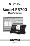
![Main lSetup l Cleanup] Parameters Locals}](http://vs1.manualzilla.com/store/data/005794368_1-f1180d1b21e5ef681561217b8f35e179-150x150.png)