1
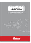
Water heating for your PV system
Installation and user guide
v1.1
2
Contents
1
Overview
4
2
Technical Specifications
5
3
Installation
6
3.1
Mounting
6
3.2
Electrical Connections
7
3.3
Clamp Installation
8
3.4
Wiring Diagrams
8
Installer Settings
12
4.1
DIP Switch Settings
12
4.2
Installation Setup
13
4.3
Installer Menu
14
User Operation
16
5.1
Controls and Display
16
5.2
Changing Values
16
5.3
Normal Operation Display
17
5.4
Main Menu
18
5.5
Manual Hot Water Boost
19
5.6
Error Messages
19
6
Troubleshooting
20
7
Legionella Advice
21
8
Warranty
22
9
Conformance
23
4
5
24
10 Commissioning Sheet
3
1. Overview
Thank you for choosing immerSUN. This intelligent device is a sensible and practical addition to your PV
or Wind micro generation system.
Water is heated via your existing immersion heater, using surplus power that would otherwise have been
exported to the grid.
Please read and follow this guide to ensure many years of trouble-free operation and savings!
Key features
•
•
•
•
•
•
•
•
•
•
•
•
•
•
Heats water from your PV system or Wind Turbine
Effectively adjusts power levels to the immersion heater, keeping the exported
power at virtually zero
The consumer no longer needs to be at home to use the free electricity,
whatever the weather
No need to change the immersion heater
Suitable for all electrical microgeneration systems
Built-in hot water boost timer
Manual hot water boost function
Back-lit LCD display shows energy saved, output power and operating mode
Dual immersion heater control option
Internal multi-function relay in-addition to the modulated power output
Up to 4 devices can be daisy-chained for master / slave operation
MODBUS RS485 interface for system expansion and external data logging
Internal thermal protection
3 year product warranty
4
2. Technical Specifications
Electrical Specifications
Description
Nominal
Minimum
Maximum
Supply Voltage (VAC)
240
220
260
Supply Frequency (Hz)
50Hz
45Hz
55Hz
Load Current (A)
13
-
16
Load Power (kW)
3
-
3.2
Relay Contact Voltage (VAC)
-
-
250
Relay Contact Current (A)
-
-
16
Clamp Current (A)
-
-
100
Recommend Generation Size (kW)
-
2
10
Dimensions and weight
Width (mm)
150
Depth (mm)
64
Height (mm)
140
Weight (g)
935
5
3. Installation
3.1 Mounting
Often, the most suitable location for the immerSUN is near to the consumer unit. Usually all the
connections required are available here.
The following should be considered when deciding upon the most suitable location:
•
Close to the main incoming mains electrical supply of the property
•
Access to immersion heater supply cable (this is usually at the consumer unit)
•
Access to suitable supply via 16A MCB or 13A fused outlet
•
User access to immerSUN controls and visibility of LCD screen
•
Adequate ventilation – keeps vents clear and provide airflow around the unit
•
Cable access point – through the rear or bottom of the unit
Use the 3 screws and wall plugs provided to mount the immerSUN at the chosen location.
Remove LCD protective cover after mounting the unit.
DO NOT BLOCK VENTS! The enclosure may get hot, always keep vents clear of obstruction and allow
sufficient clearance from walls, ceilings and other objects. Observe minimum clearances as shown below.
100mm
0mm
50mm
100mm
6
3.2 Electrical Connections
Electrical connections should be made only by a competent person. Do not attempt to wire this unit if you
are not a qualified or an experienced electrician. Installation may involve alterations to fixed wiring and
opening the consumer unit, there is risk of death by electrocution.
Choose the most suitable cable entry points (rear or bottom) and make the electrical connections to the
unit according to the appropriate wiring diagram (see section 3.4). Use the blanking plugs provided for
unused cable entry points.
Alternative loads
In some cases it may be desired to control the power to a load other than an immersion heater. The load
MUST be a simple resistive load, e.g. an electric towel radiator, storage heater etc.
The load must not exceed 3kW and must not include digital or analogue timers, as they may be damaged
by the proportional output control of the immerSUN.
IMPORTANT!
Be sure to fully tighten terminals, checking the cables are securely clamped by the terminals and the cord
grips. Failure to ensure good connection could result in fire or permanent damage to the unit.
NOTE: The screw terminals are 'rising clamp' type.
TERMINALS
MAINS
IN
LIVE IN
240V supply input, should be from 16A MCB or 13A fused outlet
OUT
LIVE OUT
Live output to immersion heater, maximum load 13A or 3kW
N
NEUTRAL (x3)
Mains Neutral terminals (All Neutral terminals are internally connected)
E
EARTH (x3)
Mains Earth terminals (All Earth terminals are internally connected)
IMPORTANT! Earth MUST be connected
RELAY (used for some additional functions, see wiring diagrams in section 3.4)
NO
NORMALLY OPEN
Volt-free normally open relay contact (max. current 13A)
COM
COMMON
Volt-free common relay contact (max. current 13A)
NC
NORMALLY CLOSED
Volt-free normally closed relay contact (max. current 13A)
CURRENT
AC current transformer clamp terminals
CLAMP
CT
COMMUNICATIONS
A
RS485 A
RS485 communication terminal A (D+)
B
RS485 B
RS485 communication terminal B (D-)
GND
DIGITAL GND
Ground connection for future use
5V
5V OUTPUT
5-volt output connection for future use
7
3.3 Clamp Installation
Correct positioning of the clamp is vital to the operation and efficiency of the immerSUN. Incorrect
installation may result in increased electrical costs to the user.
The clamp should be located at the main incoming grid supply to the building. This will be the supply from
the main electric meter (NOT the PV generation meter). Close the clamp around one of the cables (Live
or Neutral) from the meter, this can be at the meter location or inside the consumer unit.
IMPORTANT! Ensure the clamp is securely closed around the cable.
Connect the clamp wire to the CLAMP terminals inside the immerSUN. Don't worry about polarity.
The clamp wire can be extended if required, however due to the small signal from the clamp, twisted-pair
cable should be used to help eliminate possible interference. A maximum length of 50m is recommend.
Where there is more than one consumer unit, the clamp should be installed at the primary incoming
supply (i.e. before it splits).
3.4 Wiring Diagrams
Single Immersion Heater
COMMS CLAMP
MAINS
RELAY
N N N
IN
OUT
NO
COM
NC
CT
CT
A
B
GND
5V
E E E
240V AC MAINS SUPPLY
From 16A MCB or
13A fused outlet
COMMS LINK
If slave units are used,
Link with A & B connections
CLAMP
Install onto incoming mains
Live or Neutral cable to building
ISOLATOR
Must be double-pole
IMMERSION HEATER
Max. Load 3kW
For simple single heater control, relay connections not required, comms link only needed if slave devices are used. (Also see
Alternative Mains Wiring diagram).
8
Alternative Mains Wiring
E
MAINS
N N N
IN
OUT
E E E
N
16A
CONSUMER UNIT
With 16A MCB
1.5mm 4-Core
ISOLATOR
Must be double-pole
IMMERSION HEATER
Max. Load 3kW
As an alternative to using two flex cables, one 4-core cable may be used for the mains wiring.
Two Heaters
COMMS CLAMP RELAY
MAINS
N N N
IN
OUT
NO
COM
NC
CT
CT
A
B
GND
5V
E E E
240V AC MAINS SUPPLY
From 16A MCB or
13A fused outlet
COMMS LINK
If slave units are used,
Link with A & B connections
1
CLAMP
Install onto incoming mains
Live or Neutral cable to building
2
ISOLATORS
Must be double-pole
IMMERSION HEATERS
Max. Load 3kW each
(Other loads can be used)
Two heaters can be controlled by using the multi-function relay. The heaters need not be in the same cylinder. Heater no. 1 takes
priority.
9
Boiler Hot Water Boost
COMMS CLAMP
MAINS
RELAY
N N N
IN
OUT
NO
COM
NC
CT
CT
A
B
GND
5V
E E E
240V AC MAINS SUPPLY
From 16A MCB or
13A fused outlet
COMMS LINK
If slave units are used,
Link with A & B connections
BOILER HW CALL
Volt-free contact
Connect to boiler wiring
CLAMP
Install onto incoming mains
Live or Neutral cable to building
ISOLATOR
Must be double-pole
IMMERSION HEATER
Max. Load 3kW
Rather than using the immersion heater to boost hot water, an external heat source e.g. a boiler can be used by making use of the
multi-function relay wired to the boiler hot water controls.
De-strat Pump
COMMS CLAMP
MAINS
RELAY
N N N
IN
OUT
NO
COM
NC
CT
CT
A
B
GND
5V
E E E
240V AC MAINS SUPPLY
From 16A MCB or
13A fused outlet
COMMS LINK
If slave units are used,
Link with A & B connections
IMMERSION HEATER
Max. Load 3kW
CLAMP
Install onto incoming mains
Live or Neutral cable to building
DE-STRAT PUMP
With 3A fused isolator
It may be desirable to use a de-stratisfication pump to mix the cooler water at the bottom of the bottom of the cylinder with the hot
water at the top, this allows a top mounted immersion heater to heat all of the water in the cylinder.
10
Threshold Switch
COMMS CLAMP
E E E
N N N
IN
OUT
CLAMP
Install onto incoming mains
Live or Neutral cable to building
NO
COM
NC
CT
CT
A
B
GND
5V
COMMS LINK
If slave units are used,
Link with A & B connections
MAINS
RELAY
240V AC MAINS SUPPLY
From 16A MCB or
13A fused outlet
APPLIANCE LIVE SWITCH
Volt-free contact
Can be used to switch live
feed to appliance.
NOTE: If load exceeds 13A,
a separate contactor
must be used.
ISOLATOR
Must be double-pole
IMMERSION HEATER
Max. Load 3kW
The multi-fuction relay can be used to switch any load on for a set duration, once an export threshold has been reached. The
maximum relay current should not be exceeded (an additional contactor may be used for larger loads).
Fault Signal
COMMS CLAMP RELAY
MAINS
N N N
IN
OUT
NO
COM
NC
CT
CT
A
B
GND
5V
E E E
240V AC MAINS SUPPLY
From 16A MCB or
13A fused outlet
COMMS LINK
If slave units are used,
Link with A & B connections
CLAMP
Install onto incoming mains
Live or Neutral cable to building
TO BMS SYSTEM
Volt-free contact
Contact is closed when
unit Is powered.
Contact opens if fault
occurs.
ISOLATOR
Must be double-pole
IMMERSION HEATER
Max. Load 3kW
If a fault signal for a BMS system is required, the multi-function can be set to de-activated when a fault occurs.
11
4. Installer Settings
Once the unit is mounted and wired, the installer will need to set parameters as required for the particular
installation. Before applying power to the unit the DIP switches will need to be set.
4.1 DIP Switch Settings
The default position of the DIP switches, is all four set to ON. For the majority of installations this will be
the correct setting. However if slave units are connected then they may need to be set differently, see
table below.
Default settings show in Italics
S1
OFF
S2
OFF
MODBUS Address Select
Notes
st
1 Slave
Clamp not used, control is via master
nd
OFF
ON
2 Slave
Clamp not used, control is via master
ON
OFF
3rd Slave
Clamp not used, control is via master
ON
ON
Master / Software Selected Address
Clamp is required
S3
Termination Resistor Select
ON
RS485 termination resistor ENABLED
OFF
RS485 termination resistor DISABLED
S4
Clamp Burden Resistor Select
ON
Internal burden resistor ENABLED
OFF
Internal burden resistor DISABLED
Set to ON if this is at the end of the communication chain. If
the unit is in the middle of the chain, set to OFF. Where
there are only two devices connected, set both to ON.
Use external resistor (for supporting alternative clamps)
12
4.2 Installation Setup
At first switch on, the immerSUN will run through the installation setup process, follow the instructions on
the display.
Step 1
INSTALLATION
SETUP – PRESS >
Press ► to start the installation setup process as
instructed. Otherwise press ◄ to cancel.
Step 2
Ensure that the heater isolator is ON and that the
thermostat is closed (i.e. the water in the cylinder is cold)
TURN ON HEATER
THEN PRESS >
ERROR! HEATER
NOT DETECTED
An error will occur if no load is detected, the immersion
heater may be switched off at the isolator, or the
thermostat open because the water is hot already.
Press ◄ to go back to step 1
Step 3
(master only)
Step 4
(master only)
CHECKING
HEATER...
The immerSUN will then perform a test to check the
output and the heater.
TURN INVERTER
OFF THEN PRESS >
You will be asked to switch off the inverter, this is so the
immerSUN can detect import/export direction.
Use the AC isolator of the PV system.
SETTING UP
PLEASE WAIT...
Setting up will take about one minute.
INSUFFICENT
LOAD FOR TEST
If the import power is too small. This could be because
the inverter is still switched on, or the heater thermostat
is open circuit.
Press ◄ to go back to step 1
Step 5
Once setup has finished this message will be displayed.
INSTALLATION
SETUP COMPLETE!
Switch inverter back on again. Wait for inverter to start
working, this usually takes 3 minutes.
If export is high enough the immerSUN will start heating
water, otherwise you will see the waiting screen.
Step 6
13
4.3 Installer Menu
Installer Menu Options (Press and hold▼AND ▲ for 5 seconds for installer menu)
Description
Menu Screen
Installer Menu
INSTALLER MENU
PRESS >
Sub Menus
Press and hold▼AND ▲ for 5 seconds for installer
menu, you will then see this screen, press ► to
continue to installer menu.
View Readings
Set Load
The output can be set
to a given percentage
for testing purposes
Relay Function
The internal multifunction relay can be
set to operate as one
of 7 different functions.
(The currently enabled
option is shown in
brackets).
See appropriate wiring
diagram for chosen
relay function
INSTALLER MENU
View Readings
INSTALLER MENU
Set Load (Auto)
INSTALLER MENU
Relay (OFF)
View Readings
AC Volts: 245V
AC Volts
Shows AC mains voltage at present.
View Readings
Grid I: 12.5A
Grid I
Shows AC mains current at clamp.
View Readings
Load I: 8.2A
Load I
Shows AC mains current applied to load.
View Readings
Temperature: 38C
Temperature
Shows internal temperature on the immerSUN.
SET LOAD
>Auto<
Auto (Normal mode)
Set output to automatically track exported power.
SET LOAD
>100%<
Manual
Manually set output power for testing purposes only.
RELAY FUNCTION
>Two Heaters<
Two Heaters (2 Heater)
Use relay to switch load output between two heaters.
Heater no.1 output takes priority (see wiring diagram).
Heater no. 2 output only heats when no.1 is fully heated.
RELAY FUNCTION
>Water Boost<
Water Boost (Boost)
Relay controls boiler to heat water when in water boost
mode, rather than using the immersion heater.
RELAY FUNCTION
>De-strat Pump<
De-stratification Pump (De-strat)
Relay controls cylinder de-stratification pump.
Pump is activated when immersion thermostat opens
and runs until thermostat closes again.
(The immersion thermostat is checked only once a
minute so there may be a delay before the pump stops).
RELAY FUNCTION
>Threshold<
Threshold (Threshld)
Relay operates when an export threshold is reached,
relay remains activated for set period of time, even if
export drops. Export threshold level and relay on
duration can be set as shown below:
THRESHOLD SET
Export: 500W
THRESHOLD SET
Duration: 1h30m
RELAY FUNCTION
>Fault Signal<
Fault Signal (Fault)
Relay is deactivated if a fault condition occurs.
RELAY FUNCTION
>Always On<
Always On (ON)
Relay is operated continuously.
(This is for testing purposes only).
RELAY FUNCTION
>Always Off<
Always Off (OFF)
Relay is disabled. (This is the default relay function).
14
Comms Options
Options for setting up
communication
between devices
Reset Settings
INSTALLER MENU
Comms Options
INSTALLER MENU
Reset Settings
COMMS OPTIONS
Comms: Disabled
Communications Enable/Disable
Communication should be disabled unless slaves are
connected or MODBUS is needed.
COMMS OPTIONS
Baud: 9600
Baud Rate
Baud rate is speed communication data transfer in bits
per second.
(The default baud rate is 9600)
COMMS OPTIONS
Address: Master
Device Address
The communication address of the device, each device
connected should have a unique address.
If DIP switches for slave devices are ON they will
override this setting.
(The default address is Master)
RESET SETTINGS
CONFIRM Press >
Reset Settings
Use to setup immerSUN after installation.
(See section 4.2).
15
5. User Operation
5.1 Controls and Display
LCD DISPLAY
STATUS LED
SET / BOOST
BACK
DOWN
Button
UP
Operation
Alt. Operation
Description
◄
BACK
SCREEN CHANGE
Exit menu or change screen when not in menus
▼
DOWN
MENU
Go down through list or decrease value
Enter Main Menu
▲
UP
MENU
Go up through list or increase value
Enter Main Menu
►
SET
BOOST
Set value or hold to boost hot water
5.2 Changing Values
To change values, navigate to value you wish to change and press ►
Arrows either side of the value to change will then be shown. Use the ▼and▲buttons to change the
value. Press ► again to store the new value. Pressing ◄ will exit edit mode, without changing the
value.
Non-Edit Mode
SET TIME
16:01
Press ► to edit value.
Edit Mode
SET TIME
16>01<
Value to be edited is indicated by > < symbols.
16
5.3 Normal Operation Display
The table below summarises the operation of the immerSUN. There a four main modes of operation:
Heating Water; Water Hot; Waiting and Hot Water Boost. The mode is shown on the LCD display, the
LED allows the mode to be determined from a distance.
The display changes every two seconds, showing the mode with additional information, the time and
date, and the savings in kWh.
Normal Operation
Mode & LED status
Waiting...
Mode Information
Time & Date
Savings
Description
Waiting...
Waiting...
10:52
16/02/12
Today: 12.562kWh
Total: 5651kWh
Waiting for sufficient exported
power to start heating water.
Heating Water
Output: 2925W
Heating Water
10:52
16/02/12
Today: 12.562kWh
Total: 5651kWh
Heating water with power from
PV system, no Grid power is
being used.
The current output power applied
to load is shown.
Heating Water(2)
Output: 2925W
Heating Water(2)
10:52
16/02/12
Today: 12.562kWh
Total: 5651kWh
Heating water with power from
PV system, no Grid power is
being used. Current heater is
show in brackets.
Water Hot
Water Hot
10:52
16/02/12
Today: 12.562kWh
Total: 5651kWh
The water is fully heated, the
immersion thermostat is open.
Hot Water Boost
ON for: 1h 15m
Hot Water Boost
10:52
16/02/12
Today: 12.562kWh
Total: 5651kWh
Heating water at full power,
regardless of available export
power.
●
Heating Water
●○
Heating Water
(Dual Heater Mode)
●○
Water Hot
●
Hot Water Boost
●○
Master / Slave Operation
Slave Devices
Status Screen
Status of Slaves
HEAT WAIT ----
When MODBUS is enabled and the device
is set as Master, this screen will be shown
giving the status of all the slave devices in
the system.
17
Status Abbreviations
HEAT : Heating Water
HOT : Water Hot
WAIT : Waiting for sufficient
export power
ERR! : Error
---- : No device detected
5.4 Main Menu
Main Menu Options (Press ▼OR ▲ for main menu)
Description
Menu Screen
Sub Menus
View Savings
MAIN MENU
View Savings
Savings
Today: 12.563kWh
Today
Show savings made today in kWh.
Savings
Month: 224kWh
Month (current month)
Show savings made this month in kWh.
Savings
MAR: 224kWh
Month (each month)
Show savings made in the indicated month in kWh.
Savings are stored for each month of the year.
Savings
Year: 1791kWh
Year
Show savings made this year in kWh.
Savings
Total: 3215kWh
Total
Shows total energy saved to date in kWh.
The immerSUN
measures and records
energy applied to
immersion heater. As
only the renewable
energy is counted this
is effectively saved
energy.
View Event Log
MAIN MENU
View Event Log
Power On
14:53
12/06/12
Code: 7
Value: 0
Log Details
Every normal operation event is
logged along with the time and
date of the event.
Code is the event code number.
Value is the value associated
with the event.
View Fault Log
MAIN MENU
View Fault Log
POWER FAILED
14:53
12/06/12
Code: 105
Value: 0
Log Details
Every change of status and any
faults are recording in the log
along with the time and date of
the event.
Code is the fault code number.
Value is the value associated
with the fault.
Settings
MAIN MENU
Settings
SETTINGS
Set Time
SET TIME
16:01
Set Time
Time is used for Hot Water Boost
and the event log. Time is
maintained during power
outages for at least 48 hours.
SETTINGS
Set Date
SET DATE
12/06/12
Set Date
The date is used for the event
log.
Date is maintained during power
outages for at least 48 hours.
SETTINGS
Set Contrast
SET CONTRAST
>20%<
Set Display Contrast
The display contrast can be
adjusted if required.
cont...
18
Timed Boost
MAIN MENU
Timed Boost
TIMED BOOST (A)
06:30 – 0h 30m
Timed Boost A
The water heating can be boosted to ensure hot water
by a given time. When heating water in boost mode, the
immersion heater will be fully on regardless of available
free power.
Set the On time and Duration for timed hot water boost.
If timed water heating boost is not required, set the
duration to 0h 0m.
TIMED BOOST (B)
17:00 - 1h 15m
Timed Boost B
Water heating boost can be set for twice a day (A & B).
Set the On time and Duration for timed hot water boost.
If timed water heating boost is not required, set the
duration to 0h 0m.
5.5 Manual Hot Water Boost
In addition to the timed hot water boost option, the water heating can be boosted manually. You may wish
to use this function if you have an unexpected hot water demand. See section 5.4 for Timed Boost option.
Manual Boost
Manual Boost
ON for: >1h 00m<
To manually boost the hot water, press and hold ►then use
the▼and▲buttons if you want to change the boost time. Confirm boost by
pressing ►again. The Hot Water Boost operation will then start
The water heating will then be boosted for the set duration, or until the water is
hot, whichever is sooner.
Hot Water Boost
CANCELLED
To cancel boost mode, press and hold ◄ for 2 seconds.
5.6 Error Messages
If a fault condition occurs, an error message will be displayed and the LED will flash red. The error will be
logged in the Fault Log. Normal operation will continue once the immerSUN is reset.
Error Messages
The internal temperature of the
immerSUN is too high.
Check vents are clear.
UNIT TEMPERATURE
TOO HOT
●○
MAINS VOLTAGE
TOO HIGH
MAINS VOLTAGE
TOO LOW
AC supply voltage is outside of
the operating parameters.
ERROR
CLAMP REVERSED
The clamp has been reversed,
the settings will need to be reset
to reconfigure the unit.
(See section 4.3 Reset Settings)
ERROR
OUTPUT OVERLOAD
The output of the unit is
overloaded, the heater is larger
than 3kW.
19
6. Troubleshooting
Use the table below to help remedy the problem.
Any actions requiring opening the immerSUN and/or testing voltages should only be carried out a
competent person. Contact your installer if in doubt.
Symptom
Possible Cause
Action
Unit dead, no display
MCB Tripped
Check MCB is ON
LIN and LD terminals swapped
Check supply voltage on LIN terminal
Internal Fuse Blown
Test fuse inside immerSUN
Showing Water Hot even though
the water is cold
No load present on LD terminal
Immersion heater isolator should be ON
Always showing Waiting...
PV system not generating
sufficient power
Wait for PV system power increase or reduce demand
by switching off appliances
Problem with signal from clamp
Check clamp is fitted to correct cable
Clamp reversed
The clamp has been reversed,
the settings will need to be reset to reconfigure the unit.
(See section 4.3 Reset Settings)
Check immersion heater thermostat is not open
Immersion heater element could be open-circuit
Check clamp wire connections to terminals
Heating water at full output even
when PV is not exporting
Slave device status not showing on Communication link wires not
master display
properly connected
Slave status screen not showing
on master
Check continuity of communication wires to terminals A
&B
Address conflict
Check DIP switch positions
MODBUS not enabled on master
Check MODBUS is enabled in Comms menu
Address settings incorrect
Check DIP switch positions
7. Legionella Advice
The legionella bacteria is present in all source water. The concentration, however is normally too low to
be a risk to health. The growth of the bacteria and hence the concentration is dependent on stagnation
time, temperature and nutrient availability.
A domestic hot water storage cylinder in the UK is unlikely to remain stagnant in the cylinder for much
more than a day under normal occupation of the premises. In addition the mains cold water supply is very
low in nutrients, as it is often treated with chlorine which remains in the water and is toxic to the bacteria.
Nevertheless, if the premises are unoccupied for any length of time, such as absence on holiday, it is
good practice to sterilise the system using the immersion heater or an auxiliary heat source before using
any hot water. This applies whether or not a solar water heating system is fitted.
It is recommended to set the hot water boost function, or use existing hot water boiler controls to
be sure that the water is heated up to 60°C once a day.
20
8. Warranty
Subject to the provisions described below, this product is protected for three (3) year against defects in
material and workmanship.
Should this product fail to perform as described within the warranted period, it will be repaired or replaced
with the same or functionally equivalent product by 4eco, at its discretion, free of charge provided you: (1)
Return the failed product to 4eco with shipping charge prepaid, and (2) provide 4eco with proof of the
original date of purchase. Returned or replacement products will be returned to you with shipping charges
prepaid.
Replacement products may be refurbished or contain refurbished materials. If 4eco, by its sole
determination, is unable to repair or replace the defective product, it will refund the depreciated purchase
price of the product.
The warranty does not apply if, in the judgement of 4eco, the product fails due to damage from shipment,
handling, storage, accident, abuse, misuse, or if it has been used or maintained in a manner not
conforming to product manual instructions, has been modified in any way, or has had any serial number
removed or defaced. Repair by anyone other than 4eco or an approved agent will void this warranty. The
maximum liability of 4eco under this warranty is limited to the purchase price of the product covered by
the warranty.
Prior to returning any defective product, the end customer or the reseller from whom the end customer
originally purchased the product must obtain a Return Materials Authorisation (RMA) number from 4eco.
All defective products should be returned to 4eco with shipping charges prepaid. 4eco will not accept
collect shipments.
Except as specifically provided in this agreement or as required by law, the warranties and remedies
stated above are exclusive and in lieu of all others, oral or written, express or implied. Any and all other
warranties, including implied warranties or merchantability, fitness for a particular purpose and noninfringement of third party rights are expressly excluded. 4eco shall not under any circumstances be liable
to any person for any special, incident, indirect or consequential damages, including without limitation,
damages resulting from use or malfunction of the products, loss of profits or revenues or costs of
replacement goods, even if 4eco is informed in advanced of the possibility of such damages.
21
9. Conformance
EC Declaration of Conformity
In accordance with EN ISO 17050-1:2004
We
4eco Ltd
of
3 Church View Business Centre
Binbrook, Lincolnshire, LN8 6BY, England
In accordance with the following Directives:
2006/95/EC
The Low Voltage Directive
2004/108/EC
The Electromagnetic Compatibility Directive
Hereby declare that:
Equipment
Heater controller for microgeneration systems
Model
immerSUN
Is in conformity with the applicable requirements of the following documents
Ref. No.
Title
Edition/Date
BS EN 61000-6-1
Electromagnetic compatibility (EMC). Generic 2007
standards. Immunity for residential, commercial
and light-industrial environments
BS EN 61000-6-3
Electromagnetic compatibility (EMC). Generic
standards. Emission standard for residential,
commercial and light-industrial environments
2007
I hereby declare that the equipment named above has been designed to comply with the relevant
sections of the above referenced specifications. The unit complies with all applicable Essential
Requirements of the Directives.
Signed:
Name:
Lee Sutton
Position:
Technical Director
On:
12 July 2012
22
10. Commissioning Sheet
Model
Serial Number
Installation Company
Installer Name
Date of Installation
Legionella advice given?
See section 7
(tick when done)
Signed by Installer
23
4eco Ltd, 3 Church View Business Centre, Binbrook, Lincolnshire, LN8 6BY, England
+44 (0)1472 398838