1
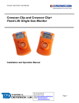
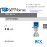
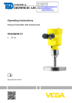
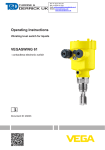
Operating instructions
Magnetic-inductive flow sensor
UK
SM6004
704594 / 00
04 / 2010
Tel: +44 (0)191 490 1547
Fax: +44 (0)191 477 5371
Email: [email protected]
Website: www.heattracing.co.uk
www.thorneanderrick.co.uk
Contents
1 Preliminary note��������������������������������������������������������������������������������������4
1.1 Symbols used������������������������������������������������������������������������������������������������4
2 Safety instructions�����������������������������������������������������������������������������������������������4
3 Functions and features����������������������������������������������������������������������������������������5
4 Function���������������������������������������������������������������������������������������������������������������5
4.1 Processing of the measured signals��������������������������������������������������������������5
4.2 Volumetric flow monitoring�����������������������������������������������������������������������������5
4.3 Monitoring of temperatures����������������������������������������������������������������������������5
4.4 Volumetric flow or temperature monitoring / analogue function ��������������������6
5 Installation�����������������������������������������������������������������������������������������������������������6
5.1 Installation location����������������������������������������������������������������������������������������6
5.2 Installation in pipes����������������������������������������������������������������������������������������9
5.3 Protection against high medium temperatures��������������������������������������������10
6 Electrical connection������������������������������������������������������������������������������������������10
7 Operating and display elements������������������������������������������������������������������������ 11
8 Menu������������������������������������������������������������������������������������������������������������������12
8.1 Menu structure���������������������������������������������������������������������������������������������12
8.2 Explanation of the menu������������������������������������������������������������������������������13
9 Parameter setting����������������������������������������������������������������������������������������������14
9.1 General parameter setting���������������������������������������������������������������������������14
9.2 Scaling of the analogue value for temperature��������������������������������������������16
9.3 Scaling of the analogue value for volumetric flow���������������������������������������16
9.4 User settings (optional)��������������������������������������������������������������������������������16
9.4.1 Determine the standard unit of measurement for volumetric flow������16
9.4.2 Determine the standard unit of measurement for temperature�����������16
9.4.3 Configuration of the standard display�������������������������������������������������16
9.4.4 Setting the damping of the measured values�������������������������������������16
9.4.5 Setting the error behaviour of OUT1 / OUT2��������������������������������������17
9.5 Service functions�����������������������������������������������������������������������������������������17
9.5.1 Reading the min./max. values for volumetric flow������������������������������17
9.5.2 Reading the min./max. values for temperature�����������������������������������17
9.5.3 Reset all parameters to the factory setting�����������������������������������������17
2
10 Operation���������������������������������������������������������������������������������������������������������18
10.1 Read the set parameters���������������������������������������������������������������������������18
10.2 Changing the display unit in the Run mode�����������������������������������������������18
10.3 Error indication������������������������������������������������������������������������������������������18
10.4 General operating conditions���������������������������������������������������������������������19
11 Scale drawing��������������������������������������������������������������������������������������������������19
12 Technical data��������������������������������������������������������������������������������������������������20
12.1 Setting ranges ������������������������������������������������������������������������������������������21
13 Factory setting�������������������������������������������������������������������������������������������������22 UK
3
1 Preliminary note
1.1 Symbols used
►
>
[…]
→
Instruction
Reaction, result
Designation of buttons, switches or indications
Cross-reference
Important note
Non-compliance can result in malfunctions or interference.
2 Safety instructions
• Please read this document prior to installing the unit. Ensure that the product is
suitable for your application without any restrictions.
• Improper or non-intended use may lead to malfunctions of the unit or to
unwanted effects in your application. That is why installation, electrical connection, set-up, operation and maintenance of the unit must be carried out by
qualified personnel authorised by the plant operator.
• In all applications test the compatibility of the product materials (→ 12 Technical data) with the media to be measured.
For the scope of validity cULus:
The device shall be supplied from an isolating transformer having a secondary
Listed fuse rated either
a) max 5 amps for voltages 0~20 Vrms (0~28.3 Vp) or
b) 100/Vp for voltages of 20~30 Vrms (28.3~42.4 Vp).
4
3 Functions and features
The unit monitors liquids.
It detects the process categories volumetric flow and medium temperature.
Application area
Conductive liquids with the following properties:
• conductivity: ≥ 20 µS/cm
• viscosity: < 70 mm2/s at 40 °C (< 70 cSt at 104°F).
4 Function
UK
4.1 Processing of the measured signals
• The unit displays the current process values.
• It generates 2 output signals according to the parameter setting.
-- OUT1: analogue signal for temperature.
-- OUT2: analogue signal for volumetric flow.
4.2 Volumetric flow monitoring
The medium flows through a magnetic field. It generates a signal voltage which is
directly proportional to the volumetric flow.
• An analogue signal proportional to the volumetric flow (4...20 mA) is provided
on output 2. For the analogue functions → 4.4.
In addition to the flow velocity, the unit also detects the flow direction. The positive
flow direction is marked on the unit by an arrow (“flow direction” → 5.2).
• Flow = “flow direction”: process value and display positive.
• Flow against the “flow direction”: process value and display negative.
Only positive process values are processed for the signal output..
4.3 Monitoring of temperatures
• An analogue signal proportional to the temperature (4...20 mA) is provided on
output 1. For the analogue functions → 4.4.
5
4.4 Volumetric flow or temperature monitoring / analogue
function
• The analogue start point [ASP] determines at which measured value the output
signal is 4 mA.
• The analogue end point [AEP] determines at which measured value the output
signal is 20 mA.
• Minimum distance between [ASP] and [AEP] = 20 % of the final value of the
measuring range.
Example volumetric flow monitoring
Factory setting
Measuring range scaled
MEW = final value of the measuring range
In the set measuring range the output signal is between 4 and 20 mA.
It is also indicated:
Volumetric flow above the measuring range: output signal > 20 mA.
5 Installation
5.1 Installation location
►► Install the unit so that the measuring pipe is always completely filled.
►► Arrange for inlet and outlet pipe lengths. Disturbances caused by bends,
valves, reductions, etc. are compensated for. It applies in particular: no shut-off
and control devices are allowed directly in front of the unit.
6
S = disturbance; D = pipe diameter; F = flow direction
►► Install in front of or in a rising pipe.
UK
F = flow direction
►► Avoid the following installation locations:
• Directly in front of a falling pipe.
• In a falling pipe.
F = flow direction
7
• At the highest point of the pipe system.
• Directly in front of the spout of a pipe.
F = flow direction
The unit can be installed independently of the orientation if the following is
ensured:
-- No air bubbles can form in the pipe system.
-- The pipes are always completely filled.
• On the suction side of a pump.
F = flow direction
If installed in an ungrounded pipe system (e.g. plastic pipes) the unit must
be grounded.
Ground brackets for the G½ thread are available as accessories (order number E40196).
A = cable lug (not included in the scope of supply).
8
5.2 Installation in pipes
The unit is installed in the pipe using adapters. Adapters have to be ordered separately as accessories.
-- Order no. E40199: 2 adapters for R½ pipes + 2 seals.
-- Order no. E40200: 2 adapters for pipes ½“ NPT + 2 seals.
UK
1. Screw the adapter (B) into the pipe (A).
2. Place the seals (C) and install the unit according to the marked flow direction.
3. Screw the adapter (B) with the threads (D) until it is hand-tight.
4. Tighten the two adapters in opposite direction (tightening torque: 30 Nm).
The unit can also be used in G¾ fittings. To do so, first screw an adapter
G½ - G¾ (B) with O-ring (C) on both
threads (D) of the unit.
Place the seals (A) and install the unit
according to the marked flow direction.
Adapters have to be ordered separately as accessories.
-- Order no. E40189: 2 adapters G½ - G¾ + 2 O-rings + 2 seals).
After installation air bubbles in the system can affect the measurement. Help:
►► Rinse the system after installation for ventilation (rinsing quantity > 3 l/min. /
1 gpm).
In cases of horizontal installation: As a result of design requirements a small
quantity of the medium always remains in the measuring channel after switching
off the pump.
9
5.3 Protection against high medium temperatures
For medium temperatures over 50 °C (122 °F) some parts of the housing can heat
up to over 65 °C (140 °F).
►► Protect the housing against contact with flammable substances and unintentional contact.
6 Electrical connection
The unit must be connected by a qualified electrician.
The national and international regulations for the installation of electrical
equipment must be adhered to.
Voltage supply to EN50178, SELV, PELV.
►► Disconnect power.
►► Connect the unit as follows:
1
2
2
1
L+
4
3
Pin1
Pin3
Pin4 (OUT1)
Pin2 (OUT2)
4
2: OUT2
4: OUT1
3
Ub+
UbAnalogue signal for temperature.
Analogue signal for volumetric flow.
For information about available sockets/connectors see:
www.ifm.com → Products → Accessories
10
L
7 Operating and display elements
1 to 8: Indicator LEDs
- LED 1 = current volumetric flow in litres/minute.
- LED 2 = current volumetric flow in cubic metres/hour.
- LED 3 = current volumetric flow in gallons per minute (gpm).
- LED 4 = current volumetric flow in gallons per hour (gph).
- LED 5 = current medium temperature in °C.
- LED 6 = current medium temperature in °F.
- LED 7, LED 8 = not used.
9: Alphanumeric display, 4 digits
- Indication of the current volumetric flow (if [SELd] = [FLOW] is set).
- indication of the current medium temperature (if [SELd] = [TEMP] is set).
- indication of the parameters and parameter values.
10: Mode/Enter pushbutton
- Selection of the parameters and acknowledgement of the parameter values.
11: Set pushbutton
- Setting of the parameter values (scrolling by holding pressed, incremental by pressing
briefly).
- Change of the display unit in the normal operating mode (Run mode).
UK
11
8 Menu
8.1 Menu structure
= [Mode/Enter]
= [Set]
In the Run mode, different display units are accessible (depending on the setting of the
parameters [SELd], [Uni.F] and [Uni.T], → 10.2).
12
8.2 Explanation of the menu
ASP1
AEP1
ASP2
AEP2
EF
HI.F
LO.F
HI.T
LO.T
FOU1
FOU2
dAP
diS
Uni.F
Uni.T
SELd
res
Analogue start value for temperature.
Analogue end value for temperature.
Analogue start value for volumetric flow.
Analogue end value for volumetric flow.
Extended functions / opening of menu level 2.
Maximum value memory for volumetric flow.
Minimum value memory for volumetric flow.
Maximum value memory for temperature.
UK
Minimum value memory for temperature.
Behaviour of output 1 in case of an internal fault.
Behaviour of output 2 in case of an internal fault.
Measured value damping / damping constant in seconds.
Update rate and orientation of the display.
Standard unit of measurement for volumetric flow: litres/minute (lmin), cubic
metres/hour (m3h), gallons per minute (gpm) or gallons per hour (gph).
Standard unit of measurement for temperature: °C or °F.
Standard process category of the display: volumetric flow value or medium
temperature.
Restore factory setting.
13
9 Parameter setting
During parameter setting the unit remains in the operating mode. It continues its
monitoring function with the existing parameters until the parameter setting has
been completed.
9.1 General parameter setting
3 steps must be taken for each parameter set:
1
2
Parameter selection
►► Press [Mode/Enter] until the
requested parameter is displayed.
Setting of the parameter value
►► Press [Set] and keep it pressed.
>> Current setting value of the parameter flashes for 5 s.
>> After 5 s: The setting value is
changed: incremental by pressing briefly or scrolling by holding
pressed.
Numerical values are incremented continuously. If the value is to be reduced: let
the display move to the maximum setting value. Then the cycle starts again at the
minimum setting value.
3 Acknowledgement of the parameter
value
►► Press [Mode/Enter] briefly.
>> The parameter is displayed again.
The new setting value is stored.
Setting of other parameters:
►► Start again with step 1.
Finishing the parameter setting:
►► Press [Mode/Enter] several times until the current measured value is displayed or wait
for 15 s.
>> The unit returns to the operating mode.
14
• Change from menu level 1 to menu level 2:
►► Press [Mode/Enter] until [EF] is
displayed.
►► Press [Set] briefly.
>> The first parameter of the sub-menu
is displayed (here: [HI.F]).
UK
• Locking / unlocking
The unit can be locked electronically to prevent unintentional wrong settings.
►► Make sure that the unit is in the
normal operating mode.
►► Press [Mode/Enter] + [Set] for 10 s.
>> [Loc] is displayed.
During operation: > [Loc] is briefly displayed if you try to change parameter values.
►► Press [Mode/Enter] + [Set] for 10 s.
>> [uLoc] is displayed.
When delivered: unlocked.
• Time out:
If during parameter setting no pushbutton is pressed for 15 s, the unit exits the parameter setting mode. The parameter value is not changed.
For medium temperatures over 50 °C (122 °F) some parts of the housing
can heat up to over 65 °C (140 °F).
In this case do not press the pushbuttons manually; instead use an object.
15
9.2 Scaling of the analogue value for temperature
►► Select [ASP1] and set the value at which 4 mA is provided.
►► Select [AEP1] and set the value at which 20 mA is provided.
9.3 Scaling of the analogue value for volumetric flow
►► Select [ASP2] and set the value at which 4 mA is provided.
►► Select [AEP2] and set the value at which 20 mA is provided.
9.4 User settings (optional)
9.4.1 Determine the standard unit of measurement for volumetric flow
►► Select [Uni.F] and set the unit of measurement::
[Lmin], [m3h], [GPm] or [GPh].
9.4.2 Determine the standard unit of measurement for temperature
►► Select [Uni.T] and set the unit of measurement: [°C] or [°F].
9.4.3 Configuration of the standard display
►► Select [SELd] and determine the standard process category.
-- [FLOW] = display shows the current volumetric flow value in the standard unit of measurement.
-- [TEMP] = display indicates the current medium temperature in the
standard unit of measurement.
►► Select [diS] and determine the update rate and orientation of the display:
-- [d1] = update of the measured values every 50 ms.
-- [d2] = update of the measured values every 200 ms.
-- [d3] = update of the measured values every 600 ms.
-- [rd1], [rd2], [rd3] = display as for d1, d2, d3; rotated by 180°.
-- [OFF] = the display is switched off in the operating mode.
9.4.4 Setting the damping of the measured values
►► Select [dAP] and the damping constant in seconds (t value 63 %).
16
9.4.5 Setting the error behaviour of OUT1 / OUT2
►► Select [FOU1] and determine the value:
-- [On] = the analogue signal goes to the upper end stop value.
-- [OFF] = the analogue signal goes to the lower end stop value.
-- [OU] = the analogue signal corresponds to the measured value.
►► Select [FOU2] and determine the value:
-- [On] = the analogue signal goes to the upper end stop value.
-- [OFF] = the analogue signal goes to the lower end stop value.
-- [OU] = the analogue signal corresponds to the measured value.
9.5 Service functions
9.5.1 Reading the min./max. values for volumetric flow
UK
►► Select [HI.F] or [LO.F] and press [Set] briefly.
[HI.F] = maximum value, [LO.F] = minimum value.
Delete memory:
►► Select [HI.F] or [LO.F].
►► Press [Set] and keep it pressed until [----] is displayed.
►► Press [Mode/Enter] briefly.
It makes sense to delete the memories as soon as the unit works under
normal operating conditions for the first time.
9.5.2 Reading the min./max. values for temperature
►► Select [HI.T] or [LO.T] and press [Set] briefly.
[HI.T] = maximum value, [LO.T] = minimum value.
Speicher löschen:
►► Select [HI.T] or [LO.T].
►► Press [Set] and keep it pressed until [----] is displayed.
►► Press [Mode/Enter] briefly.
It makes sense to delete the memories as soon as the unit works under
normal operating conditions for the first time.
9.5.3 Reset all parameters to the factory setting
►► Select [rES], then press [Set] and keep it pressed until [----] is dis-
played.
►► Press [Mode/Enter] briefly.
The factory setting is listed at the end of the instructions (→ 13 Factory
setting).
It makes sense to write your own settings in this table before executing the
function.
17
10 Operation
After power on and expiry of the power-on delay time (approx. 5 s) the unit is in
the Run mode (= normal operating mode). It carries out its measurement and evaluation functions and generates output signals according to the set parameters.
• Operation indication → chapter 7 Controls and indicating elements.
• The output signals are at the maximum value during the power-on delay time.
10.1 Read the set parameters
►► Press [Mode/Enter] until the requested parameter is displayed.
►► Press [Set] briefly.
>> The unit displays the corresponding parameter value for approx. 15 s. After
another 15 s the parameter is displayed again, then the unit returns to the Run
mode.
10.2 Changing the display unit in the Run mode
►► Press [Set] briefly in the Run mode. Press the pushbutton to move to the next
display unit.
>> The unit displays the current measured value for approx. 15 s, the corresponding LED lights.
2 groups of display units are accessible (depending on the setting of the parameters [SELd] and [Uni.F] and [Uni.T]):
• [Lmin], [m3h] and the temperature unit selected in [Uni.T].
• [GPm], [GPh] and the temperature unit selected in [Uni.T].
When setting [SELd] = [FLOW], [Uni.F] = [Lmin] and [Uni.T] = [°C], for example,
[Lmin] is displayed as a standard. By pressing [Set] the display unit changes to
[m3h], [°C] and back to [lmin].
10.3 Error indication
[OL]
Detection zone of volumetric flow or temperature exceeded:
measured value between 120 % and 130 % of VMR.
[UL]
Below the detection zone of volumetric flow or temperature:
measured value between -120 % and -130 % of VMR.
[Err]
- Unit faulty / malfunction.
- Measured value greater than 130 % of VMR or smaller than -130 % of VMR.
[Loc]
Setting pushbuttons locked, parameter change rejected.
VMR = final value of the measuring range
18
10.4 General operating conditions
►► Avoid deposits, accumulated gas and air in the pipe system.
For medium temperatures over 50 °C some parts of the housing can heat
up to over 65 °C.
►► In this case do not touch the unit.
►► Protect the housing against contact with flammable substances and unintentional contact.
►► Do not press the pushbuttons manually; instead use an object.
UK
11 Scale drawing
Dimensions are in millimeters
19
12 Technical data
Application ................................................................................................ conductive liquids
Conductivity......................................................................................................... ≥ 20 µS/cm
Viscosity.................................................................. < 70 mm²/s at 40°C (< 70 cSt at 104°F)
Operating voltage [V]...........................................................................................20...30 DC1)
Current consumption [mA].....................................................................................120 (24 V)
Analogue outputs......................................................4...20 mA; measuring range scaleable
Max. load [Ω]....................................................................................................................500
Power-on delay time [s]........................................................................................................5
Flow monitoring
l/min
m³/h
gpm
gph
Measuring range
0.1...25
0.005...1.5
0.03...6.60
1.5...396.5
Resolution
0.05
0.005
0.01
0.5
Display range
-30...30
-1.8...1.8
-7.92...7.92
-475.5...475.5
Response time [ms]..................................................................................... < 150 (dAP = 0)
Damping flow signal (dAP) [s].................................................................................. 0.0...5.0
Accuracy ...................................................................................... < ± (2% MV + 0.5% VMR)
Repeatability [% VMR]...................................................................................................± 0,2
Pressure loss (dP) / flow rate (Q)
dP [mbar]
300
250
200
150
100
50
0
5
10
15
20
25
30 Q [l/min]
Temperature monitoring
Measuring range [°C / °F]........................................................................... -20...80 / -4...176
Resolution [°C / °F]....................................................................................................0.2 / 0.5
Response time [s]............................................................. T09 = 30 (Q > 1 l/min / 0.26 gpm)
Accuracy [°C / °F]................................................. ± 2.5 (Q > 1 l/min) / ± 4.5 (Q > 0.26 gpm)
20
Operating temperature [°C]....................................................................................... -10...60
Medium temperature [°C].......................................................................................... -10...70
Pressure resistance [bar]...................................................................................................16
Material (wetted parts)................................................ stainless steel (316S12); PEEK; FKM
Housing materials.......................................................................... stainless steel (316S12);
PBT-GF 20; PC (Makrolon); EPDM/X (Santoprene)
Protection................................................................................................................ IP 67 / III
Insulation resistance [MΩ]......................................................................... > 100 (500 V DC)
Shock resistance [g]............................................................... 20 (DIN / IEC 68-2-27, 11ms)
Vibration resistance [g]................................................... 5 (DIN / IEC 68-2-6, 55 - 2000 Hz)
EMC
UK
IEC 1000/4/2 ESD:................................................................................................. 4 / 8 KV
IEC 1000/4/3 HF radiated:.......................................................................................... 10 V/m
IEC 1000/4/4 Burst:........................................................................................................2 KV
IEC 1000/4/5 Surge:...............................................................................................0.5 / 1 KV
IEC 1000/4/6 HF conducted:.......................................................................................... 10 V
1)
to EN50178, SELV, PELV
MV = measured value; VMR = final value of the measuring range
12.1 Setting ranges
FLOW
l/min
m3h
gpm
gph
TEMP
°C
°F
ASP2
min
0.00
0.000
0.00
0.0
AEP2
max
20.00
1.200
5.28
317.0
min
5.00
0.300
1.32
79.5
ASP1
min
-20.0
-4.0
max
25.00
1.500
6.60
396.5
AEP1
max
60.0
140.0
min
0.0
32.0
max
80.0
176.0
∆Q
0.05
0.005
0.01
0.5
∆T
0.2
0.5
(∆Q, ∆T = step increment)
21
13 Factory setting
ASP1
AEP1
ASP2
AEP2
FOU1
FOU2
dAP
diS
Uni.F
Uni.T
SELd
Factory setting
-20.0
80.0
0.00
25.00
OFF
OFF
0,6
d2
Lmin
°C
FLOW
User setting
Technical data and further information at www.ifm.com
22