1
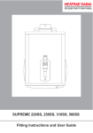
SUPREME 150, 165, 180
Fitting Instructions and User Guide
1
INTRODUCTION
Thank you for purchasing a Heatrae Sadia Supreme. The Boiling
water heater is manufactured to the highest standards and has been
designed to meet all the latest relevant safety specifications.
This Heatrae Sadia water heater must be installed (Sections 1-5),
commissioned (Section 7) and maintained (Sections 8-9) by a
competent person. Please read and understand these instructions
prior to installing your Heatrae Sadia water heater. Following
installation and commissioning the operation of the heater should be
explained to the user (Section 11) and these instructions left with them
for future reference.
This appliance is not intended for use by persons (including children)
with reduced physical, sensory or mental capabilities, or lack of
experience and knowledge, unless they have been given supervision
or instruction concerning the use of the appliance by a person
responsible for their safety. Children should be supervised to ensure
that they do not play with the appliance.
COMPONENT CHECKLIST
Before commencing installation check that all the following
components have been supplied with your Supreme heater.
•
Wall mounting bracket
•
No.12 x 2” screws (2 off)
•
No.8 x 1” screw (1 off)
•
No.12 x 2” wall plug (2 off)
•
No.8 x 1” wall plug (1 off)
•
15mm x 15mm straight push-fit connector
•
15mm x 15mm 90° elbow push fit connector
2
TECHNICAL SPECIFICATIONS
Electrical rating
2.3 - 2.5 kW 230 - 240V
(2.5 ltr)
Nominal capacities
Model 150
2.5 litres
Model 165
5.0 litres
Model 180
7.5 litres
Weight (full)
Model 150
8.4 kg
Model 165
11.8 kg
Model 180
15.4 kg
Rated pressure
0MPa (0 bar)
Minimum supply pressure
0.05MPa (0.5 bar)
Maximum supply pressure
1.0MPa (10 bar)
Enclosure rated
A-weighted sound pressure level is below
IP X2
70 dB
Nominal commissioning times (minutes) to temperature ready
Supreme 150
16
Supreme 165 24
Supreme 180
32
3
1.0 IMPORTANT INSTALLATION
POINTS
1.1 The Supreme stores and dispenses water at or close to boiling
point at all times it is switched on. Due caution must be taken
when choosing a location for the product to minimise misuse.
Locate the unit over a draining board NOT over the sink or basin.
1.2 Push fit connectors DO NOT grip chromed or stainless pipe.
1.3 The Supreme is a vented water heater. The vent pipe must never
be blocked or obstructed, it must be a minimum of 15mm outside
diameter pipe. Where the vent pipe length exceeds 3m the pipe
diameter should be increased. The vent pipe must be laid to a
continuous fall and discharge in a safe, visible position; it must
discharge via a tundish or finish a minimum of 20 mm above
a draining board. The vent pipe material must be capable of
conveying boiling water. The vent pipe must never be connected
directly to a soil pipe.
1.4 Wherever possible the Supreme should be supplied directly from a
rising main. If fed from a cold water feed cistern, the cistern must
comply with the Water Regulations Guide (clause R27.2).
It should be noted that water quality may be reduced when
supplied from a cistern and additional forms of water pretreatment
may be necessary.
1.5 In hard water areas, heated water will produce limescale which will
be deposited within the heater. If this is not regularly removed it
will impair the operation of the heater. Where rapid and excessive
scale build up is likely to occur the use of a proprietary scale
reducing device may be beneficial.
1.6 The installation must be carried out in accordance with the
relevant requirements of: • The appropriate Building Regulations either The Building Regulations, The Building Regulations (Scotland) or Building Regulations (Northern Ireland).
• The Water Fittings Regulations or Water Byelaws in Scotland.
1.7 The Supreme will adjust for ambient (room) temperatures of
between 1°C and 40°C.
1.8 When not in use care must be taken to prevent it freezing; if
thought to be frozen it must not be switched on. It must be left to
thaw and must then be thorougly inspected to ensure it is totally
thawed and undamaged.
1.9 The unit is not suitable for installation in an area where a water jet
could be used.
4
2.0 INSTALLATION - MOUNTING
2.1 The Supreme must be vertically wall mounted using the bracket
supplied. Special precautions may be required for the protection
of children and/or infirm persons.
2.2 Figure.1 details the outside dimensions of the Supreme unit.
A template is supplied to aid positioning the heater. It is
recommended that the unit is positioned above a draining board. If
this is not possible consideration should be given to any spillages
that may occur under the heater. A drip tray is available as an
accessory (Heatrae Sadia Code No. 95 970 123). The heater
should be positioned at a height to suit the items being filled
(flasks, pans, cups etc.). This is likely to position the base of the
unit 250mm above the work surface.
2.3 Sufficient room should be left around the heater for access for
maintenance and servicing. The top should not be covered as this
will reduce the efficiency of the Supreme. 2.4 Ensure that the wall can support the full weight of the unit (see
TECHNICAL SPECIFICATIONS) and that there are no hidden
services (electricity, gas or water) below the surface of the wall.
2.5 Using the template mark the fixing positions and water and vent
entry points. Drill and plug the fixing positions. Fix the mounting
bracket to the wall using the two No.12 x 2” screws provided
(confirm suitability of all screws and plugs for use with the
wall, if unsuitable due to wall type provide alternative fixings). 2.6 If rear entry services are to be used the necessary holes for these
should be prepared prior to hanging the unit onto its bracket.
2.7 Remove the front cover by: unscrewing the cover fixing screws
bottom and top. Hang the Supreme onto the wall mounting
bracket. Secure anchor point to the wall with the No.8 x 1” long
screw (provided).
5
3.0 DIMENSIONS
B
N
M
Fixing
Bracket
A
L
F
K
250mm approx
D
Fixing
Point
J
E
O
C
Worktop
I
G
H
Figure 1
MODEL
150
165
180
6
A
B
C
445
510
510
290
335
335
190
200
262
DIMENSIONS (mm)
D
E
F
INLET VENT INLET/
VENT
85
103
103
115
133
133
101
101
101
G
INLET/
VENT
H
CABLE
ENTRY
49
49
49
46
69
69
M
L
K
N
I
J
O
CABLE FIXING FIXING BRACKET BRACKET BRACKET OUTLET
ENTRY POINT POINT
150
165
180
59
61
61
96
117
117
50
71
71
342
405
405
52.5
84
84
169
217
217
152
163
225
4.0 INSTALLATION - WATER SUPPLY
4.1 Select appropriate push fit connector for chosen entry position:
Bottom entry water -
15mm x 15mm 90° elbow.
Rear entry water - 15mm x 15mm straight.
Note: stainless or chromed pipes DO NOT provide secure
connections with push fit fittings (use copper pipe at joints).
4.2 Push the connector fully home (28mm engagement) onto the
solenoid valve inlet spigot. To remove a push fit connector the
collar (collet) should be pushed towards the body of the fitting
whilst pulling the connector off the pipe.
4.3 If the inlet pipe run is horizontal and beneath the unit ensure it
does not prevent access to the case screws.
4.4 Connect the inlet pipe to the push fit connector ensuring it is fully
pushed home (28mm engagement). After connection DO NOT
make soldered joints in the pipework close to the heater, as the
heat may damage the connector or the water heater itself.
4.5 A WRAS listed isolating valve should be fitted to the cold supply to
facilitate servicing the heater.
4.6 Push fit connectors are supplied to allow either bottom or rear
entry of services (see figure 2). If a combination of entry points are
required an additional connector will be required as follows:
Bottom inlet, rear vent
15mm x 15mm elbow
(Heatrae Sadia part no. 95 607 510)
Rear inlet, bottom vent
15mm x 15mm straight
(Heatrae Sadia part no. 95 607 509)
7
Inlet
Vent
Bottom entry
Vent / Inlet
Rear entry
Figure 2
5.0 INSTALLATION - VENT PIPE
5.1 Select appropriate push fit connector for chosen entry position:
Bottom entry vent - 15mm x 15mm straight
Rear entry vent - 15mm x 15mm 90° elbow
5.2 Push the connector fully home (28mm engagement) onto the vent
pipe connection.
5.3 Connect the vent pipe to the push fit connector ensuring it is
pushed fully home (28mm engagement). Refer to the vent pipe
requirements detailed in IMPORTANT INSTALLATION POINTS.
If a bottom entry vent pipe is used the pipe must terminate below
the unit, in a safe visible position. After connection DO NOT make
soldered joints in the pipework close to the heater, as the heat
may damage the connector or the water heater itself.
8
6.0 INSTALLATION - ELECTRICAL
REQUIREMENTS
5.1 This appliance must be earthed.
5.2 The installation, supply cable and circuit protection must conform
to the latest BS7671 ‘Requirements for electrical installations’ (IEE Wiring Regulations).
5.3 The appliance must only be connected to a 230/240 V ac supply. A double pole isolating switch, with a contact separation of at least
3mm in both poles, must be incorporated in the electrical supply. The supply should be fused 13Amp.
5.4 If the Supreme is to be unused for significant periods of time running costs can be reduced by switching the unit off. It is recommended that this is done automatically by incorporating a
suitable timeswitch in the supply to the unit. The use of a accessory No. 95 970 124 is recommended. The timeswitch can then be set to switch the unit on for a suitable period to allow it to heat up before it is next to be used. NOTE:A timeswitch must be capable of switching 13 Amps resistive load.
SCHEMATIC
WIRING
WIRING
SCHEMATIC
LOWER
SENSOR
EARTH
UPPER
SENSOR
EARTH
2.5 kW
ELEMENT 'A'
H
N
W
L1
S
ELECTRONIC CONTROL
L2
SOLENOID
VALVE
L3
1
2
UPPER LEVEL SENSOR
LOWER LEVEL SENSOR
STEAM THERMISTOR
J5
J7
Figure 3
5
6
7
8
9
10
1
WATER THERMISTOR
1
SCALE
CONDITIONING
FIELD WINDING
'AT TEMP' LED ANODE
'AT TEMP' LED CATHODE
'POWER ON' LED ANODE
'POWER ON' LED CATHODE
PRIMARY
CUTOUT 'A'
L N
TERMINAL BLOCK
9
7.0 COMMISSIONING
7.1 The electronic control system of the Supreme has a self
commissioning and calibration function. Once the heater is
installed and all services have been connected the unit should
require no further adjustment before use.
7.2 Check that all electrical, water and vent pipe connections have
been made and are secure.
7.3 Replace the cover and secure with the fixing screws. Ensure the
tank discharge tube is centrally located in the outlet spout. Turn on
water and electrical supply.
7.4 The READY indicator will flash to indicate the unit is in its “selfcommissioning” mode. The water in the unit will not be hot enough
to use at this stage (DO NOT DRAW ANY WATER OFF WHILST
COMMISIONING).
7.5 The READY indicator will continue to flash until the unit has
reached boiling and has “self-calibrated”. At this point the READY
indicator will remain illuminated. If for any reason the calibration
procedure is interrupted it will restart after a short delay but may
result in the calibrated temperature being too low. If this occurs
switch the electrical supply OFF for several seconds and then
switch ON. The calibration sequence will reset. Wait for the
READY indicator to remain illuminated.
7.6 The unit is now ready to use, however, it is recommended that the
first few fills be drawn off and discarded to ensure the freshness of
the water.
7.7 The tap sealing washer pressure has been already set. If the tap
drips after commissioning adjust the spring tension so that the
handle is just loose. a) Remove the tap bezel after removing the two screws securing
it. Note: to remove the bezel the handle will have to be
operated. This will cause water to discharge from the outlet.
b) Tighten the tap headwork nut (turn clockwise) until the handle is
just loose. Replace bezel and securing screws. Note: excessive
adjustment will dismantle the tap, if heated this would result
in the uncontrollable release of boiling water.
7.8 Check for leaks.
10
8.0 MAINTENANCE
NOTE: Maintenance must be carried out by competent persons.
Competent - i.e. trained, experienced, qualified.
Disconnect the electrical supply before removing the cover.
WARNING: electronics control by switching ‘N’ (neutral), in some
instances neutral terminations will be at 230 volts with respect to
earth.
Maintenance instructions are available from the Heatrae Sadia Service Department. Telephone 0844 871 1535, Fax 0844 871 1543.
8.1 The Supreme incorporates an electronic scale conditioning
function which will reduce the rate of scale deposition in hard
water areas. However, some deposits may still occur in the
storage tank; these should be periodically removed.
8.2 The amount of usage of the unit will also determine the quality
of scale build up. A regular inspection of the tank every 6 to
12 months will provide longer life of the product and optimum
performance (removal of the steam plate assembly will give acess
to the storage tank).
8.3 The front cover and spout will require a periodic wipe to clean any
marks/splashes from use.
11
9.0 FAULT FINDING
YOUR HEATRAE SADIA SUPREME SHOULD GIVE TROUBLE
FREE OPERATION. HOWEVER SHOULD A FAULT OCCUR
THE TABLE BELOW SHOULD ALLOW MOST FAULTS TO BE
IDENTIFIED. FAULT FINDING SHOULD ONLY BE CARRIED OUT
BY A COMPETENT PERSON.
SYMPTOM
No indicator lights
POSSIBLE CAUSE
1. If no water or heat – no power to
unit
2. If hot water available – no power
to indicator diodes
Unit does not fill on commissioning
1. If “ON” indicator not illuminated – 1. Check power supply is correctly
no power to unit
connected and switched on and that
primary cutout has not operated
2. If “READY” light flashing – water 2. Check water supply
supply not turned on
3. Check operation of solenoid valve,
3. Solenoid fault
replace if necessary
4. Low water pressure
Unit does not heat on commissioning 1. If “ON” indicator not illuminated –
no power to unit
2. If “READY” light flashing – water
supply not turned on
No indicator lights
3. Check operation of solenoid valve,
replace if necessary
4. Low water pressure
5. Element fault
4. Check supply
5. Check element continuity. If faulty
replace
1. Check power supply is correctly
connected and switched on and that
primary cutout has not operated
2. Check connections to indicators at
4 way plug
1. If no water or heat – no power to
unit
1. If “ON” indicator not illuminated –
no power to unit
2. If “READY” light flashing – water
supply not turned on
3. Solenoid fault
4. Low water pressure
Water flows from vent and primary
cutout activates
1. Check power supply is correctly
connected and switched on and that
primary cutout has not operated
2. Check water supply
3. Check operation of solenoid valve,
replace if necessary
4. Check supply
1. Solenoid valve fault
1. Check operation of solenoid valve.
Replace if necessary
2. Level sensor fault
2. Check level system earth
connections
3. Check connections to electronic
control. Replace if necessary
4. Increase inlet pressure
3. Electronic control fault
4. Low water pressure
12
4. Check supply
1. Check power supply is correctly
connected and switched on and that
primary cutout has not operated
2. Check water supply
3. Solenoid fault
2. If hot water available – no power
to indicator diodes
Unit does not fill on commissioning
ACTION
1. Check power supply is correctly
connected and switched on and that
primary cutout has not operated
2. Check connections to indicators at
4 way plug
SYMPTOM
Steam from vent pipe and primary
cutout operates
Drips from outlet
Water "runs on" when tap released
POSSIBLE CAUSE
ACTION
1. Control thermistor fault - open
circuit
1. Check continuity (5Kohms at
100°C, 100Kohms at 25°C)
2. Electronic control fault
2. Check connections to electronic
control. Replace if necessary
3. Scale build up
3. Descale unit
1. Incorrect spring tension
1. Ensure tap headwork nut correctly
adjusted
2. Scale : debris under tap seal
3. Damaged tap seal
2. Remove and clean as necessary
3. Replace tap seal
4. Scale on tap outlet spout
4. Clean tap outlet
1. Scale on tap outlet spout
1. Clean tap outlet
2. Scale : debris under tap seal
2. Remove and clean as necessary
3. Damaged tap seal
3. Replace tap seal
Stale taste to water
Unit left unused for several days
Empty and allow to refill before use
Tap sticks open
Water consistently cooler than when
new
Dirt around handle pivot
Clean with a stiff paint brush
1. Control thermistor pocket has a
1. Descale the pocket surface & unit
covering of scale
2. Control thermistor out of
2. Check values (5Kohms at 100°C,
calibration
100Kohms at 25°C)
3. Steam thermistor out of calibration 3. Check values (5Kohms at 100°C,
100Kohms at 25°C)
For any faults that cannot be identified using the Fault Finding chart
please contact the Heatrae Sadia Service Department, telephone
0844 871 1535, fax 0844 871 1543.
13
10.0 SPARE PARTS
The following comprehensive list of spare parts is available for your Supreme
water heater. Please refer to the rating label on the right hand side of your
heater before ordering to ensure the correct spare parts are obtained.
DO NOT REPLACE WITH PARTS NOT RECOMMENDED BY HEATRAE
SADIA - THIS WILL INVALIDATE YOUR GUARANTEE AND MAY RENDER
THE INSTALLATION DANGEROUS.
1. Element assembly 2.5kW (incorporating start dry cutout)...........95 606 952
2. Element assembly sealing gasket................................................95 611 816
3. Primary cutout (vent pipe)............................................................95 612 001
4. Solenoid valve assembly..............................................................95 605 877
5. Level sensor assembly (2.5ltr Model)..........................................95 606 971
Level sensor assembly (5.0/7.5ltr Model)....................................95 606 972
6. Circuit board (All Models).............................................................95 615 007
7. Outlet tap headwork (inc. handle)................................................95 605 019
8. Outlet tap stem.............................................................................95 605 832
9. Outlet tap cup seal.......................................................................95 611 731
10.Bezel for tap & cover....................................................................95 605 020
11.Cover assy & screws (2.5ltr Model).............................................95 607 197
Cover assy & screws (5.0ltr Model).............................................95 607 198
Cover assy & screws (7.5ltr Model).............................................95 607 199
12.Steam condenser assy (2.5ltr Model)..........................................95 607 015
Steam condenser assy (5.0ltr Model)..........................................95 607 016
Steam condenser assy (7.5ltr Model)..........................................95 607 018
13.Condenser sealing gasket (2.5ltr Model).....................................95 611 817
Condenser sealing gasket (5.0ltr Model).....................................95 611 819
Condenser sealing gasket (7.5ltr Model).....................................95 611 820
14.‘O’ ring kit.....................................................................................95 611 002
15.Manifold assy 2.5ltr......................................................................95 607 206
Manifold assy 5.0ltr......................................................................95 607 207 Manifold assy 7.5ltr......................................................................95 607 208
16.Outlet spout plastic - tank............................................................95 604 668
17.Outlet spout - cover......................................................................95 604 001
18.Push fit connector 15x15 straight.................................................95 607 509
19.Push fit connector 15x15 elbow...................................................95 607 510
20.Tank (2.5ltr Model).......................................................................95 608 926
Tank (5.0ltr Model).......................................................................95 608 927
Tank (7.5ltr Model).......................................................................95 608 928
21.Tank drain & seal.........................................................................95 608 929
22.Start dry cutout (element)............................................................95 612 691
23.Solenoid valve coil.......................................................................95 605 839
24.Fitting kit (2.5ltr Model)................................................................95 607 024
25.Fitting kit (50./7.5ltr Model)..........................................................95 607 025
26.Wiring harness 4-way...................................................................95 612 006
27.Wiring harness complete (2.5ltr Model).......................................95 612 042
Wiring harness complete (5.0/7.5ltr Model).................................95 612 043
14
17
Figure 4
15
11
4
7
23
8
19
5
3
9
10
6
18
14
14
13
16
15
21
14 20
14
13
12
2
1
22
11.0 USER INSTRUCTIONS
11.1 Once installed the filling and heating cycles of the Supreme are
completely automatic.
11.2 To dispense water, a suitable container having been placed
under the outlet spout, the tap handle should be pulled down
and towards (or pushed away from) the user. The water
dispensed will at all times be boiling or close to boiling point so
due caution must be taken when using the product, especially if
it is likely to be used by children, aged or infirm persons.
11.3 The tap handle is spring loaded so that when released it will
spring back to the “off” position (no flow). 11.4 The Supreme is fitted with two indicators to give a visual
indication of the unit’s status.
ON
Will be illuminated as long as the electrical supply to
the Supreme is switched on.
READY When fully illuminated indicates that the stored water
is hot enough to use.
11.5 If the store of hot water is completely withdrawn, the flowrate
from the outlet tap will reduce to the filling rate of the heater. This slow flowrate allows the incoming water to be instantly
reheated, it does not indicate a fault with the water heater.
11.6 If the Supreme is not used for a few days the water may
become “stale”. In these instances it is advisable to draw off
the contents and discard the water at least twice to remove the
“stale” water. This will ensure that “freshly” boiled water is used
to make your drinks etc.
11.7 Similarly, if left unused it is possible that some scale residue
will collect in the outlet tap. This will cause the outlet water
to appear “milky” for a short while. If this condition occurs
it is recommended that the first few cups are drawn off and
discarded.
16
GUARANTEE
This Supreme water heater is guaranteed for a period of two years
from the date of purchase provided:
1. The unit has been installed in accordance with these instructions
and all necessary inlet, vent and electrical connections have been
fitted correctly.
2. Any valves or controls are of Heatrae Sadia recommended type.
3. The unit has not been tampered with and has been regularly
maintained as detailed in the maintenance instructions.
4. The unit has been used only for heating potable water.
5. It has been installed in the UK.
The unit is not guaranteed against damage by frost or due to the build
up of scale. Please note that if Heatrae Sadia personnel or agents
are requested to descale a unit, this work will be chargeable.
This guarantee does not affect the statutory rights of the consumer.
The policy of Heatrae is one of continuous product development and,
as such, we reserve the right to change specifications without notice.
ENVIRONMENTAL INFORMATION
This product is manufactured from many recyclable materials. At
the end of its useful life it should be disposed of at a Local Authority
Recycling Centre.
17
Notes:
18
Notes:
19
Spares Stockists
For the fast and efficient supply of spares please contact the stockists
listed below.
Electric Water Heating Co. 2 Horsecroft Place, Pinnacles
Harlow, Essex, CM19 5BT
Tel: 0845 0553811
E-Mail: [email protected]
SPD
Units 9 & 10 Hexagon Business Centre
Springfield Road, Hayes
Middlesex, UB40 0TY
Tel: 020 8606 3567
Parts Center
Tel: 0845 270 9800
www.partscenter.co.uk
Newey & Eyre
Specialist Products Division
Please contact your local branch
UK Spares Ltd.
Tower Lane, Warmley
Bristol, BS30 8XT
Tel: 0117 961 6670
William Wilson Ltd.
Unit 3A, 780 South Street
Whiteinch, Glasgow, G14 OSY
Tel: 0141 434 1530
Advanced Water Company Ltd
Unit DS Enterprise Way
Vale Park, Evesham
Worcs, WR11 1GS
Tel: 01386 760066
Service: Service Fax:
Service Email:
0844 871 1535
0844 871 1543 heatraesadiaservice@
heateam.co.uk
Heatrae Sadia Heating
Hurricane Way Norwich NR6 6EA
www.heatraesadia.com
20
© 2009
36 00 6035
Issue 1