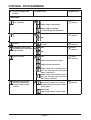
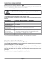
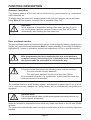
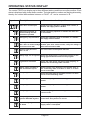
1
Electrical operating
Operating
instructions
Door
Control Panel
TS 970
Software 3.3
GB
(Design and functions subject to change)
51171271 / 12.2005
OPERATING INSTRUCTIONS
Page
SAFETY DIRECTIONS ................................................................................................... 4
INSTALLATION ADVICE ................................................................................................ 6
INSTALLATION OVERVIEW .......................................................................................... 7
ENCLOSURE INSTALLATION ...................................................................................... 8
CONNECTING THE CONTROL AND THE ELEKTROMATEN® ............................................................. 8
MAINS SUPPLY ............................................................................................................. 9
PHASE ROTATION ........................................................................................................ 10
MOTOR CONNECTION (internal wiring) ....................................................................... 10
RAPID ADJUSTMENT OF THE LIMITS ........................................................................ 11
HARDWARE OVERVIEW .............................................................................................. 12
WIRING DIAGRAM ........................................................................................................ 13
CONTROL PROGRAMMING ......................................................................................... 14
Operating mode ........................................................................................................... 15
Door position ................................................................................................................ 15
Functions ..................................................................................................................... 16
Safety functions ........................................................................................................... 17
Adjustment only for ELEKTROMATEN® with speed changer DU ............................... 18
Maintenance cycle counter .......................................................................................... 19
MEMORY CHECK .......................................................................................................... 20
RESET ............................................................................................................................ 20
SAFETY DEVICES ......................................................................................................... 21
Safety edge system with optional connection for shutter pass - door or
slack wire switch contact. X2 .......................................................................................... 21
Mounting the spiral cable ................................................................................................ 21
Typ 1: Resistance evaluation 1K2 with normally closed safety edge contact ............... 22
Typ 2: Resistance evaluation 8K2 with normally open safety edge contact ................. 22
Typ 3: Optical safety edge (Fraba Brand) ..................................................................... 22
Page 2
Page
SAFETY DEVICES ......................................................................................................... 23
Function of the safety edge system ............................................................................. 23
Emergency stop X3 .................................................................................................... 23
FUNCTION DESCRIPTION............................................................................................ 24
Key switch (latching) interrupt automatic closing X4 ................................................... 24
Internal pushbutton / Three position switch / Key switch X5 ..................................... 24
Automatic closing ......................................................................................................... 24
Automatic closing interruption ...................................................................................... 24
Photo-beam for Closing Direction X6 ......................................................................... 25
Interruption of photo beam function ............................................................................ 25
Ceiling pull switch / Radio control X7 ......................................................................... 26
Key switch – intermediate stop X8 ............................................................................. 26
Potential free changeover contact X9 ........................................................................ 26
Door overload monitor ................................................................................................. 27
Overrun correction ....................................................................................................... 27
Maintenance cycle counter .......................................................................................... 28
Short circuit / overload monitor .................................................................................... 28
OPERATING STATUS DISPLAY .................................................................................... 29
TECHNICAL DATA ......................................................................................................... 32
DECLARATION OF INCORPORATION ......................................................................... 33
FUNCTION OVERVIEW ................................................................................................. 34
Page 3
SAFETY DIRECTIONS
Basic Directions
This control has been built in accordance with DIN EN 12453 Industrial, commercial and
garage doors and gates - Safety in use of power operated doors - Requirements and
DIN EN 12978 Industrial, commercial and garage doors and gates - Safety devices for
power operated doors - Requirements and Test methods; and left the factory in perfect
condition from the point of view of safety. To maintain this condition and to ensure safe
operation, the user must observe all the directions and warnings contained in these operating
instructions.
In principle, only trained electrical craftsmen should work on electrical equipment. They must
assess the work which has been assigned to them, identify potential danger sources and take
suitable safety precautions.
Reconstruction of or changes to TS 970 are only permissible with the approval of the manufacturer.
Original replacement parts and accessories authorised by the manufacturer guarantee safety.
Liability ceases to apply if other parts are used.
The operational safety of an TS 970 is only guaranteed if it is used in accordance with the
regulations. The limiting values stated in the technical data should not be exceeded under any
circumstances (see corresponding sections of the operating instructions).
Safety Regulations
During the installation, initial operation, maintenance and testing of the Control Panel, it is
necessary to observe the safety and accident-prevention regulations valid for the specific
application.
In particular, you should observe the following regulations (this list is not exhaustive):
European normative
DIN EN 12445
Safety in use of power operated doors - Test methods
DIN EN 12453
Safety in use of power operated doors - Requirements
DIN EN 12978
Industrial, commercial and garage doors and gates Safety devices for power operated doors - Requirements and Test methods
Please check normative´s bellow.
VDE-regulations
DIN EN 418
Safety machinery
Emergency stop equipment functional aspects
Principles for design
DIN EN 60204-1 / VDE 0113-1
Safety of machinery - Electrical equipment of machines - Part 1:
Prescriptions générales
DIN EN 60335-1 / VDE 0700-1
Safety of household and similar electrical appliances - Part 1:
General requirements
Regulations
- Please ensure that the local regulations relating to the Safety of Operations of Doors are followed
Page 4
SAFETY DIRECTIONS
Explanation of warnings
These operating instructions contain directions which are important for using the ELEKTROMATEN® appropriately and safely.
The individual directions have the following meaning:
DANGER
This indicates danger to the life and health of the user if the appropriate
precautions are not taken.
CAUTION
This warns that the ELEKTROMATEN® or other materials may be damaged if
the appropriate precautions are not taken.
General warnings and safety precautions
The following warnings are to be understood as a general guideline for working with the
ELEKTROMATEN® in conjunction with other devices. These directions must be observed
strictly during installation and operation.
Check that all screw connections are secure before operating the control
and adjusting the limit switches.
Please observe the safety and accident prevention regulations valid for
the specific application.
The ELEKTROMATEN® must be installed with the authorised coverings
and protective devices. Care should be taken that any seals are fitted
correctly and screw couplings are tightened correctly.
In the case of ELEKTROMATEN® with a permanent mains connection, an
all-pole main switch with appropriate back-up fuse must be provided.
Check live cables and conductors regularly for insulation faults or
breakages. When a fault is detected in the cabling, the defective cabling
should be replaced after immediately switching off the mains supply.
Before starting operation, check whether the permissible mains voltage
range of the devices corresponds to the local mains voltage.
With three – phase motor connection it must have right phase rotation
Page 5
INSTALLATION ADVICE
After the ELEKTROMATEN® is fitted we recommend the following procedure to rapidly reach
a fully functioning door.
• Installation
Enclosure installation
page 8
• Installation
Wiring the Drive to the Control
page 8
• Check
Mains supply
page 9
• Check
Phase rotation
page 10
• Programming
Rapid limit adjustment
page 11
The door is ready to work in Dead man mode.
• Installation
Safety devices
page 13, 19
• Programming
Door functions
page 14
The door is ready to work in automatic mode.
Check connection of external devices e.g. push button etc.
Overview to connect external devices see diagram (page 13).
After the devices are connected the programming of the control panel must be finalised.
(page 14).
Page 6
INSTALLATION OVERVIEW
Important!
Using the connection cable out side the building is not permitted.
Connection cable ELEKTROMAT® for
Motor and DES ( electronic limit)
Spiral cable for
Safety edge system
11
4
Mains supply
5
Photo-beam
5
Pull switch
3
Three push button
5
Key switch (latching) interrupt
automatic closing
Emergency stop
Key switch (latching) intermediate stop
Signal lamp
( )
Number of cores in the cable
Page 7
3
3
3
3
ENCLOSURE INSTALLATION
Before mounting the enclosure, the surface has to be checked for flatness, slope and freedom
from vibrations. Mounting must be vertical. It is important that the door can be clearly seen
from the position of the control through-out its travel.
CONNECTING THE CONTROL AND THE ELEKTROMATEN®
After the drive and control are fitted they can be connected with a plug-in cable. The cable
has plugs on each end and for easy fitting. The plugs for motor and control panel are different
and cannot be interchanged.
Control panel TS 970
ELEKTROMAT®
Motorconnection (MOT)
Connection cable for
digital limit (DES)
PE
3
4
PIN
-1
5-
-2
6-
-3
PIN
-6
2-
Motor plug to control unit
- Wire-No.
3
2
1
4
PE
Excution:
Phase W
Phase V
Phase U
Neutral (N) (not used)
Earth
Limit plug-in to control panel TS 970 (DES)
PIN
1
2
3
4
5
6
- Wire-No.
5
6
7
8
9
10
-5
-4
Cable identification
PIN
1
2
3
4
5
1
2
3
2
1
4
PE
4-
Motor plug-in
Excution:
Safety chain 24V DC
RS485 B
GND
RS485 A
Safety chain
8V DC
Page 8
MAINS SUPPLY
The CONTROL PANEL TS 970 has a universal electric supply and works with the following
supplies. (See diagram Fig.1-5)
Important note!
The bridge must be fitted into the right terminal otherwise the print could be
destroyed.
External fuse!
External fuse in the main supply should be max. 10A delayed.
The supply disconnect device (Main switch or CEE plug) must be installed between 0,6m
and 1,7m above floor level.
DANGER! To the life and health thru electric shock.
Before mounting the mains supply must be switched OFF.
With terminal 1.5, 1.6 und 1.7 the mains supply input can be selected.
For 400V – mains supply the bridge 1.5 to 1.6 must be fitted
For 230V - mains supply the bridge 1.6 to 1.7 must be fitted.
Mains supply terminal
Fig.: 1
Fig.: 4
symmetric winding
Fig.: 2
Fig.: 5
asymmetric winding
Fig.: 3
Drive unit with DU speed controller
works only with 3x 400V. A supply
3x230V or 1x 230V is not allowed
Page 9
MOTOR CONNECTION (internal wiring)
Three-phase 3 x400 V AC, N, PE
Star connection
Three-phase 3 x230 V AC, N, PE
Delta connection
Important note!
For 3x400V AC PE no
neutral, the brake
rectifier must be
connected between
terminal V and starpoint terminal.
brown
blue
brown
blue
supply for
brake
rectifier
supply for
brake
rectifier
Single-phase 1x230 V AC, N, PE
symmetrical winding
Single-phase 1x230 V AC, N, PE
asymmetrical winding
On several ELEKTROMATEN® the connection U1 und V1 on the motor-plug are
interchanged.
PHASE ROTATION
Important Notice!
After the Mains supply has been connected by inserting the CEE plug in the
appropriate socket or turning on the main switch, confirm that the phase rotation
is correct by checking that the door opens when the OPEN push button is
operated.
If the door closes when operating the OPEN push button reverse two phases
at the terminal X1.
DANGER! To the life and health through electric shock.
Before changing phase rotation the mains supply must be switched OFF.
Page 10
RAPID ADJUSTMENT OF THE LIMITS
When the phase rotation has been checked the Rapid limit adjustment can be made.
The final setting can be made with the fine adjustment (Control Programming page 15).
Safety limits and pre-limits are automatically adjusted.
1. Setting final limit open
Door open
Display
blinking
press button to reach upper limit
2. Memorise the final limit open
Display
changes
Press stop-button for 3 sec. until
the display changes
3.Setting the final limit close
Door close
Display
blinking
press button to reach lower limit
4. Memorise the final limit close
Display
changes
Press stop-button for 3 sec. until
the display changes
The Rapid adjustment is finished
The door could be moved in DEADMAN mode UP/DOWN
Further adjustments see programming mode
Page 11
HARDWARE OVERVIEW
MOT
X1
DES
COM
1.5 1.6 1.7
1.1
1.2
1.3
1.4
V1
F1 = 1,0A t
FT
2.1
2.2
2.3
2.4
2.5
1.8
1.9
9.1
9.2
9.3
PE PE PE PE 3.1 3.2 4.1 4.2 5.1 5.2 5.3 5.4 24V GND 6.1 6.2 7.1 7.2 8.1 8.2
X9
X3
X2
X4
X5
X6
S1
X7 X8
Description Print:
X1 Mains supply
external supply 230V
1.9 = L1 fused with F1 = 1A
1.8 = N
(only with 3 x 400V, N, PE und 1 x 230V, N, PE)
X2 Safety edge system and pass-door plug
X3 Emergency push-button
X4 Key switch (latching) interrupt automatic closing
X5 Three- push button / key switch
X6 Light barrier reflective or receiver- transmitter type
X7 Ceiling pull switch / Radio control
X8 Key switch for intermediate stop
X9 Potential free relay contact
warning light or annunciator
Page 12
S1
V1
MOT
DES
COM
Selector switch
7-segment display
Motor connection
Limit connection
Interface
Internal pushbutton
WIRING DIAGRAM
Terminal box Bridge
Normallyclosed contact 1K2
pass or / slack wire
switch contact
end-of-line
resitor 1K2
spiral cable
plug-in bridge
pass or / slack wire
switch contact
spiral cable
end-of-line
resitor 8K2
plug-in bridge
Terminal box Bridge
Optical safty edge system
pass or / slack wire
switch contact
brown
green
white
spiral cable
Page 19, 20
Terminal box Bridge
Normallyopen contact 8K2
plug-in bridge
Receiver
Transmitter
or
or
Open
Open/
Close
Stop
Key switch
(latching) interrupt
automatic closing
Three push button
station
Key switch with stop
button
or
Reflective photobeam
Key switch
Stop
Close
Page 21, 22, 23, 24
Emergency
stop button
Open/
Close
or
Transmitter- Receiver
photo-beam
Ceiling pull switch
Radio receiver
or
Key switch intermediate
stop
Aux. contact
Warning light
Page 13
N L1
L1 fused via
F1 = 1At
CONTROL PROGRAMMING
1. Enter programming Mode
Press selector switch for 3 sec. until display = 00
2. Chose program and confirm
and
Turn selector
Press selector
3. Adjustment
Functionen
Door position
or
Turn selector
Press foil buttons
4. Memorise
Functionen
Door position
or
Press selector
Press stop-button
further adjustments
5. Exit programming
and
Turn selector until display = 00
Press selector
Page 14
CONTROL PROGRAMMING
2. Choose program and
confirm
3. Adjustment
4. Memorise
Operating mode
Door function
Dead man OPEN
Dead man CLOSE
Press
selector
Self-hold OPEN
Dead man CLOSE
Self-hold OPEN
Self-hold CLOSE
Self - hold OPEN, CLOSE
(X5) release for external pushbutton
function only dead man close
Door position
Final limit open
coarse adjustment
Move door
upwards or downwards
Press stop
Button
Final limit close
coarse adjustment
Move door
upwards or downwards
Press stop
Button
Final limit open
fine adjustment
Final limit open can change
without door movement using +/-
Press
selector
Final limit close
fine adjustment
Final limit close can change
without door movement using +/-
Press
selector
Pre-limit safety edge
fine adjustment
Pre-limit safety edge can
change using +/-
Press
selector
Intermediate stop
Move to intermediate stop
Press stop
Button
Relay switch position
Move to relay switch
position
Press stop
Button
See page 11: Limit switch rapid - Adjustment
Page 15
CONTROL PROGRAMMING
2. Choose program and
confirm
3. Adjustment
4. Memorise
Functions
Safety edge function in
Pre - limit area
Safety edge is activated
Press
selector
Safety edge is deactivated
Safety edge is activated
+ automatic ground adjustment
Overrun correction
OFF
Press
selector
ON
Automatic closing
feature
time can be set between 1 - 240 sec.
0 = OFF
Press
selector
Automatic closing after
photo-beam is interrupted
and re-made
OFF
Press
selector
Relay function
OFF
ON
Press
selector
Switch contact impulse signal
Switch contact continuous
Signal lamp starts flashing with 3
sec. pre-warning time when door
Open’s and Close’s
Signal lamp starts flashing with 3
sec. pre-warning time only when
door Close’s direction
Step by Step function
(X7): only Ceiling pull
switch / Radio remote
control
Commands
door travels to Open or Æ Closed
position during closing door Stops
and re-opens
Commands
OpenÆStopÆCloseÆStopÆ Open
Page 16
Press
selector
CONTROL PROGRAMMING
2. Chose program and
confirm
3. Adjustment
4. Set
Safety functions
Door overload monitor
OFF
Press
selector
Coarse monitoring
Fine monitoring
Photo beam interrupt
function
OFF
ON
Page 17
Press
selector
CONTROL PROGRAMMING
2. Choose program and
confirm
3. Adjustment
4. Memorise
Adjustment only for ELEKTROMATEN® with speed changer DU
OPENING speed
Output speed OPEN - rpm
Press
selector
CLOSING speed
Output speed CLOSE - rpm
Press
selector
HIGHER CLOSING
speed
Increased closing speed
to a height of 2,5m 0=OFF
Press
selector
Changeover position
CLOSING speed
Changeover position higher/lower
closing speed
Press stop
Button
UPWARD
acceleration
rapid
Press
selector
normal
slow
DOWNWARD
acceleration
rapid
Press
selector
normal
slow
UPWARD
deceleration
rapid
Press
selector
normal
slow
DOWNWARD
deceleration
rapid
Press
selector
normal
slow
The appeared numbers for output speed open and close corresponding to
the real RPM of the drive unit.
The speed has a direct influence into operating forces.
Check again the adjustment and drive unit’s speed.
Programming:
SE 6.65 DU
P 41 rpm open Æ min. 20 rpm – max. 65 rpm
P 42 rpm close Æ min. 20 rpm – max. 30 rpm
P 43 the same as P42
Page 18
CONTROL PROGRAMMING
2. Chose program and
confirm
3. Adjustment
4. Set
Maintenance cycle counter
Counter adjustment
01-99 correspond from 1.000 up to
99.000 Count down cycles
Press
selector
Reaction when
reaching 0
Display appears „CS“ and adjusted
number of cycles
Press
selector
Changing to DEADMAN display appears
„CS“ and adjusted number of cycles
Changing to DEADMAN same as 0.2 reset
to about 500 cycles possible, press 3 sec.
Stop – Button
Page 19
MEMORY CHECK
Displayed
2. Chose program and
confirm
Info Cycle counter
7- digit
Press
selector
M
HT
ZT
T
H
Z
E
The cycles would be displayed as follow.
M = 1.000.000
H = 100
HT =
100.000
Z = 10
ZT =
10.000
E =
1
T =
1.000
Info last 2 faults
Press
selector
Info Program changes
7- digit
Press
selector
Last 2 faults would be alternately displayed.
M
HT
ZT
T
H
Z
E
The Number of program changes would be displayed as follow.
M = 1.000.000
H = 100
HT =
100.000
Z = 10
ZT =
10.000
E =
1
T =
1.000
Info Program version
Press
selector
Program version will be displayed
RESET
2. Chose program and
confirm
RESET except cycleand Program change
counter
3. Adjustment
Reset
Page 20
4. Set
Press stop
button
3 sec.
SAFETY DEVICES
Safety edge system with optional connection for shutter pass - door or slack
wire switch contact.
X2
The control recognizes and works with 3 different safety edges.
Each one needs a special 4 core spiral cable and includes an optional shutter pass - door or
slack wire switch contact.
The spiral cable connection must be made on the print with the plug provided. The opposite
side of the cable is connected to a terminal box or a signal (pressure switch) emitter.
Typ 1: Resistance evaluation 1K2 with normally closed safety edge contact
(safety edge with pressure wave switch and "Testing")
Typ 2: Resistance evaluation 8K2 with normally open safety edge contact
Typ 3: Optical safety edge (Fraba Brand)
Important note!
When connecting a safety edge, take account of DIN EN 12978 for
Industrial, commercial and garage doors and gates - Safety devices for
power operated doors - Requirements and Test methods.
Mounting the spiral cable
A bush is provided on both sides of the control box for mounting the spiral cable.
Push the plugs through into the enclosure until there is sufficient cable to allow the (2 and 3
pole) plugs to be connected to the board. The plug with two cores must be connected to the
passdoor or slack wire switch terminals. The three core plug must be connected to the safety
edge terminal.
The control panel TS 970 recognizes on first installation the safety edge system being used.
If passdoor / slack wire switch contact exists, remove bridge at terminal ST and ST+ in
the terminal box. The plug at terminal X2 must be removed.
Important note!
When using a safety edge system the automatic pre-limit adjustment must
be checked. When the safety edge is activated the door should stop and
reverse to the open position.
Page 21
SAFETY DEVICES
Typ 1: Resistance evaluation 1K2 with normally closed safety edge contact
This evaluation system is made for pressure-wave switches (N/C) within an end-of-line
resistor of 1K2 +/- 5% 0,25W.
A pressure wave is generated by compressing the rubber profile, which is conducted to the
pressure-wave switch through the plastic hose. The system should be tested in the CLOSE
position. The pre-limit would be set automatically and activate the "Testing function".
When the shutter runs over the pre-limit door position, a timer of two seconds starts to
countdown at once. If a pressure wave activates the pressure switch in this time the TS
970 recognizes the function of the safety edge. If the pressure switch has not been activated,
the control goes into fault mode and the system works only in DEAD MAN function in
downwards direction. Fault information F 2.8 would be displayed.
Pressure-wave switch - function
The contact between the contact screw and diHose contact for :
aphragm is opened (opening contact). The prespressure opens
sure-wave switch is set to a release pressure of
approx. 1,5 mbar.
contact screw
The valve screws are set to a throughput of
110 ml/min with a static admission pressure of
valve screws (may
5 mbar. This warrants that a maximum tempenot be altered)
rature increase of 30° is compensated for in
20 minutes.
The setting of the valve screws may not be altered. Should the release pressure be insufficient Pressure-wave switch
(pressure wave too insensitive), the contact
screw may be turned counterclockwise to the left by 1-2 graduation marks. The switch's
sensitivity is thus increased.
In case of excessive sensitivity, the contact screw is set clockwise by 1-2 graduation
marks (decreased sensitivity).
Typ 2: Resistance evaluation 8K2 with normally open safety edge contact
This evaluation system is made for electrical safety edges within an end-of-line resistor of
8K2 +/- 5% 0,25W. The resistor must be connected in series with the switch in the safety edge.
Typ 3: Optical safety edge (Fraba Brand)
The principle of operation is as a one way light barrier. By activating the safety edge, the
photo-beam will be interrupted.
Page 22
SAFETY DEVICES
Function of the safety edge system
With Menu 2.1 the function of the safety edge system can be chosen.
Function
Active safety edge
De-activated safety edge
Active safety edge+
downward automatic
floor adjustment
Reaction following the activation
stop
no reaction, door moves until final limit close only for
folding doors
stops and automatically re-adjusts the final limit with the
next movement
The function 'Auto ground adjustment' is used for doors with a cable e.g. Sectional doors or
vertical lift-gate. An automatic correction of slackness or change of ground height up to 2-5 cm
is possible. The slack wire switch is be still recognised.
Important note!
To use the automatic floor adjustment, the safety edge must be operated
in the door closed position by an auxiliary puffer switch.
Important !
The automatic ground adjustment works only when the following safety
edge systems are connected:
Typ 2: electrical system resistance evaluation 8K2 or Typ 3: optical safety
edge (FRABA Brand)
Important note!
When the safety edge has been operated twice the automatic closing feature
will be interrupted and fault F2.2 will be displayed.
To reset the fault press the internal pushbutton
so that the door travels
down until the final limit is reached.
Emergency stop
X3
These terminals are to connect an emergency stop button according to DIN EN 418.
Alternatively the terminals can be used to connect a safety device against entrapment (e.g.
self-testing light barrier).
Page 23
FUNCTION DESCRIPTION
Key switch (latching) interrupt automatic closing
X4
The automatic closing time can be interrupted with a normally open switch (latching)
Internal pushbutton / Three position switch / Key switch
X5
Internal and external pushbutton
Internal and external pushbutton working seperately from each other. Pushing at the same
time, the internal pushbutton has priority.
Important note!
Dead man mode UP and DOWN with internal pushbutton.
Dead man mode DOWN with external pushbutton. (Menu 0.1 Adjustment 0.4)
In Dead man mode the user shall be in full view of the door throughout
its travel.
Automatic closing
Menu 2.3 the timer works between 1 - 240 sec. If the automatic closing is active, the shutter
will close, from each limit position after the pre-adjusted time.
Important note!
The timer can be interrupted by pressing the internal pushbutton stop when
the shutter has reached a limit position. With a new command UP / DOWN
the timer is re-set.
Automatic closing interruption
Menu 2.4 can be used if the timer operation is required after interrupting and re-making the
photo-beam. The door closes after 3 seconds.
Page 24
FUNCTION DESCRIPTION
Photo-beam for Closing Direction
X6
One external photo-beam (thro’ beam or reflective photo beam) can be connected to the
control. A 24V DC supply for the photo-beam is available.
Important note!
The load on the 24 V DC power supply may not exceed 150 mA.
The light barrier is used in a normally closed operating mode.
In case the light barrier is activated or it malfunctions the contact will open and cause following
reactions.
Door Position
Reaction when Photo-beam is Interrupted
Door closed
no reaction
Door opening
no reaction
End position open *)
no reaction
without timer active
End position open *)
resets open timer for automatic closing mode
with timer active
End position open *)
With the photo-beam connected the shutter closes after
with timer active
3 sec. when the beam has been interrupted and remade
and time interruption
The time delay is cancelled and re made.
Closing Door
Stops and re-opens fully *)
*) or to the intermediate stop position when the key switch is in the on position
Interruption of photo beam function
Disabling of the photo beam re-open function, Menu 3.2.
Prevents a the door re-opening during the DOWNWARD movement when the photo beam is
switched unintentionally, e. g. by the spiral cable
To learn the switching position, the re-open function has to be interrupted for 2 full opening and
closing movements automatically after programming this function.
When the photo beam has been switched twice consecutively the switching position will be
memorised.
Thereafter the door is ready to change back to normal function.
Page 25
FUNCTION DESCRIPTION
Ceiling pull switch / Radio control
X7
It is possible to connect a ceiling pull switch or a radio receiver.
The radio receiver's switching contact must be potential free. A small receiver can be fitted
into the upper part of the housing under the cable entry.
With each command (contact) the shutter operates in the following sequence:
Shutter position
Shutter operation
Shutter closed
Shutter moves to fully open or intermediate position
Shutter moving upwards
No reaction
Shutter open
Shutter moves to fully closed position
Shutter intermediate position open Shutter moves to fully closed position
Shutter moving downwards
Shutter will STOP and moves BACK UP to final open Position*)
See commands page 16 Control menu 2.6 Adjustment 0.2 step by step function
*) or to the intermediate stop position when the key switch is in the on position
Key switch – intermediate stop
X8
Intermediate stop can be activated / de-activated by connecting a key switch (latching ONOFF). The intermediate shutter position „ PART OPEN“ is only in effect in the upwards direction
and is the new open position.
In Menu 1.6 the position can be adjusted. This is the new final position.
By turning the key switch to the OFF position, the shutter works in standard mode.
Potential free changeover contact
X9
In Menu 2.5 this contact is able to work for several functions.
Important note!
It is only possible to work with one adjusted function.
When activating the switching point the shutter must be moved to the point. Menu 1.7 must
be activated.
After a command, the lamp stars flashing for 3 seconds as pre-warning time before the
shutter moves and continues until the shutter reaches the end position. When the movement
is interrupted in between the final positions, the flashing mode continues.
Page 26
FUNCTION DESCRIPTION
Overrun correction
The stopping position of the door can be influenced by various factors e.g. temperature,
cable extension etc.
To always have the same door stopping position the overrun correction can be activated.
Using Menu 2.2 the overrun correction can be switched ON or OFF
Important!
Great variations of temperature during a time when the door is not in
use, could cause a position variation of about 1cm. This will be reset
automatically after reaching the final close limit.
Door overload monitor
The door overload monitor recognises that a person is being lifted by the door (hanging on a
handle, etc.) and could be adjusted within Menu 3.1 with a possibility of two steps of sensitivity.
Adjustment 0.1 coarse = insensitive reaction and adjustment 0.2 fine = sensitive reaction
Important!
After programming the force monitoring the door must perform a
complete opening and closing cycle in automatic mode, during which
the system reads the increments to calculate the way.
Important Note!
To have a trouble-free service the following points must be checked:
- The door must be correctly balanced
- The cable drum diameter should not be less then 160mm
Environmental influences e.g. temperature or wind load can cause the
overload monitor to be activated.
The overload monitor is a self-learning system, and checks the system from 5 cm up to ca.
2,0 m, slow-occurring changes e.g. spring tension will be automatically recognised and
equalized.
Important Note!
The overload monitor does not take place against other safety devices e.g.
(safety against entrapment)
When an overload is detected the door works only Dead man Mode in the UP and DOWN
direction.
The control unit automatically resets to impulse control when a final limit position has been
reached.
Page 27
FUNCTION DESCRIPTION
Maintenance cycle counter
Free adjustable maintenance cycle counter Menu 8.5 makes it possible to pre-adjust a max.
No of cycles until a maintenance is agreed.
The no of cycles can be adjusted from 1.000 up to 99.000; the adjustment is possible in
steps of 1.000 cycles.
Three different reactions can be chosen if the point of pre- adjusted maintenance cycles has
been reached, see Menu 8.6
Whenever the final open limit has been contacted the pre-adjusted number will be reduced
with 1 until 0 is reached.
When maintenance was done the cycle counter could be re-adjusted to a new maintenance
period and count down starts again.
Short circuit / overload monitor
The TS 970 control panel delivers 2 supplies for external devices.
230V AC; max. 1A
24V DC; max. 150mA
If the 24V DC supply is short-circuited or overloaded, the red point in the display goes out.
If the display is out, fuse F1 must be checked.
Page 28
OPERATING STATUS DISPLAY
The control TS970 can display up to three different status conditions one after another. Each
status is displayed with a letter and a number. The letter and the number are flashing alternately,
thereby the control differentiates between a FAULT = F and a command = E.
Report
Description
Measure to solve the problem
Pass door contact open
Check the proper operation of pass door contact, or
whether the supply cable is broken
Emergency operator or
motor-winding thermal
protection operated
Check emergency operator or whether the drive unit
is overloaded.
Emergency stop activated
Check the emergency stop is activated, or whether
the supply cable is broken
Failure pass door contact
Check pass door circuit’s transition resistance and
X 2.1- X 2.2 or control voltage weather pass door switch works; verify the voltage is
circuit less than 24V
OK at 24V terminal to GND
Failure input pass door
X 2.1- X 2.2
For reset switch control panel OFF-ON
Safety edge not recognised Check the safety edge is connected correctly or the
wrong type has been selected in the program
Light barrier activated
Check the light barrier has been fitted properly, or
whether the connecting cable is broken
Safety edge operated in
two consecutive cycles
Check if there is an obstacle in the shutter area, or
the connecting cable is broken or there is a short
circuit in the cable
Safety edge 8K2 activated
Check the safety edge is activated or there is a short
circuit in the connecting cable
Safety edge 8k2 defect
Check safety edge and connecting cable are not
broken
Safety edge 1K2 activated
Check safety edge and connecting cable are not
broken
Safety edge 1k2 defect
Check safety edge and connecting cable do not have
a short circuit
Safety edge 1k2 pneumatic Check the proper safety edge function and that testing
system TESTING negative in the lower door position is correct
Optical safety edge activated Check the proper safety edge function or whether the
or defect
supply cable is interrupted
Page 29
OPERATING STATUS DISPLAY
Report
Description
Measure to solve the problem
Limits not adjusted
Adjust limits
Safety open limit operated
Turn mains supply OFF and move the shutter
downwards - with the manual operator- until the
safety limit is free or the open limit should be readjusted.
Safety close limit operated
Turn mains supply OFF and move the shutter upwards
- with the manual operator- until the safety limit is
free or the close limit should be re-adjusted.
Door load monitor has activated
Check the door mechanism for tightness
ROM - Fault
Reset by switching OFF or change the control
Internal fault report
Reset by switching OFF or change the control
RAM - Fault
Reset by switching OFF or change the control
Internal control fault
Reset by switching OFF or change the control
DES – no response
Check electronic limit DES connection. Reset by
switching OFF or change the control or the electronic
limit.
Drive unit does not work
Check the shutter mechanics. Check the limit shaft
for function (turning) Check phase rotation.
Phase rotation failure
Check main supply phase rotation turns right
Closing rpm over speeded at
DU Speed Changer
Switch supply ON-OFF
If again and again, replace drive unit
Page 30
OPERATING STATUS DISPLAY
Report
Command description
open command being given
stop command being given
close command being given
→
If the normally displayed red spot is out = Short circuit or overload on the 24V supply
Page 31
TECHNICAL DATA
Housing Dimensions
Mounting
160mm x 240mm x 90mm (W x H x D)
vertical
ELEKTROMATEN® Supply
Three-phase
3 x 230 / 400V AC ± 5%, 50...60Hz
Single-phase 1 x 230V ± 5%, 50...60Hz
Power max. at 3 x 400V AC, max. 3kW
Control supply via L1,L2
400V AC or 230V AC + - 10%, 50-...60Hz,
voltage changing with bridge to 3- pole terminal,
safety fuse F1 (1A t)
External supply fuse
10A delayed
Permitted Load
ca. 15 VA (without motor and ext. 230V)
External supply 1
230V via L1 and N, safety fuse F1 (1A t)
External supply 2
24V DC uncontrolled, max. Load 150mA,
Protected via electronic fase
Inputs
24V DC / typ. 10mA
signal length must be more than 100ms
Relay output
If inductive loads are to be switched (e.g. other relays)
those have to be protected with free-wheeling Diodes
contact load at 230V max. 1A
Temperature
Working: +0.... +40°C
Storage: +0....+50°C
Humidity:
To 93% not condensing
Vibration:
Protection class
Vibration free mounting, e.g. on flat built wall
IP54 (CEE Plug), IP65 available
Page 32
DECLARATION OF INCORPORATION
according to
EC guidelines 98/37/EC
Low voltage guideline 73/23/EEC
with amendments
Electromagnetic compatibility 89/336/EEC
with amendments
We, the
GfA - Gesellschaft für Antriebstechnik
Wiesenstr. 81, 40549 Düsseldorf (Heerdt), Germany
hereby declare that the following products conform with the
above EC guidelines and are only intended for installation in door equipment.
Product description:
Door Control Panel TS 970
Harmonised norms applied
- DIN EN 12543
Safety in use of power operated doors
- Requirements
- DIN EN 12978
Industrial, commercial and garage doors and gates Safety devices for power operated doors
- Requirements and Test methods
The machinery to which this Declaration of Incorporation relates must not be put in to
service until the relevant machinery into which is to be incorporated has been declared
in conformity with the provisions of the Machinery Directive.
Düsseldorf, 23. 01. 2004
____________________________________________________
(GL, Müller)
Page 33
(QMS, U. Hohns)
FUNCTION OVERVIEW
• Control panel for ELEKTROMATEN
®
•
•
•
•
up to. 3 kW at 400V / 3~ with electronic limit DES
designed for only low-level adjustment
7- Segment led display showing
- Programming the control panel
- Displays Command - / Info- / Fault
Mains supply
- 400V / 3~ with and without Neutral
- 230V / 3~
- 230V / 1~ (for single-phase motors)
Door operating modes
- Dead-man open- and close
- Self-hold open- and dead-man mode close (without safety edge)
- Automatic open- and close (with safety edge connected)
Integrated safety edge systems
- 8K2 normally open contact
- 1K2 normally close contact
- optical safety edge system (System Fraba)
• automatic close feature
- free programmable from 1 up to max. 240 Sec.
•
•
•
•
•
- on interrupting and re-making light barrier closing after 3 sec..
- Can be interrupted by a separate switch
supply for external devices
- 230V (at 400V / 3~ with N), up to 1A load
- 24V DC, up to 150mA load
Plug for 5 pole motor connector 6 pole for electronic limit DES
Plug for spiral cable (safety edge and pass-door contact)
integrated internal pushbutton OPEN / STOP / CLOSE
Additional terminals for different control equipment
- Emergency stop ( LATCHING)
- additional safety stops
- external three push button OPEN / STOP / CLOSE
- Light barrier activated Stop and Reverse function, time reset, time interruption 3 sec.
- One channel - impulse functions e. g. Ceiling pull switch for OPEN / CLOSE / STOP
– sequencing or radio control
- Key switch ( latching) for intermediate Stop
- 1x potential free relay output (NC / NO), output signal from aux. limit
If a signal lamp is in use, the potential free limit is not available
Page 34