1
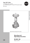
Type 3271 Pneumatic Actuator Translation of original instructions Actuator areas: 1400‑120 cm² · 2800 cm² · 2 x 2800 cm² Type 3271, 2800 cm² Type 3271, 2 x 2800 cm² (tandem actuator) Mounting and Operating Instructions EB 8310-7 EN Edition June 2015 Note on these mounting and operating instructions These mounting and operating instructions (EB) assist you in mounting and operating the de‑ vice safely. The instructions are binding for handling SAMSON devices. ÎÎ For the safe and proper use of these instructions, read them carefully and keep them for later reference. ÎÎ If you have any questions about these instructions, contact SAMSON’s After-sales Service department ([email protected]). Referenced documentation The following documents apply in addition to these mounting and operating instructions: −− Mounting and operating instructions for mounted valve −− Mounting and operating instructions for mounted valve accessories (positioner, solenoid valve etc.) −− u WA 0029 for tools and lubricant The mounting and operating instructions for all supplied devices are included in the delivery. The latest versions of the documents are available on our website at u www.samson.de > Product documentation. Definition of signal words DANGER! Hazardous situations which, if not avoided, will result in death or serious injury WARNING! Hazardous situations which, if not avoided, could result in death or serious injury 2 NOTICE Property damage message or malfunction Note: Additional information Tip: Recommended action EB 8310-7 EN Contents 1 Safety instructions and safety measures..........................................................5 1.1 Notes on possible severe personal injury..........................................................7 1.2 Notes on possible personal injury....................................................................7 1.3 Notes on possible property damage.................................................................8 2 Markings on the actuator..............................................................................10 2.1 Actuator nameplate.......................................................................................10 3 Design and principle of operation.................................................................10 3.1 Direction of action.........................................................................................12 3.2 Signal pressure routing..................................................................................12 3.3 3.3.1 3.3.2 Fail-safe action.............................................................................................12 Version with fail-safe action "actuator stem extends" (FA).................................12 Version with fail-safe action "actuator stem retracts" (FE)..................................12 3.4 Versions.......................................................................................................13 3.5 Technical data..............................................................................................13 4 Preparation..................................................................................................16 4.1 Unpacking...................................................................................................16 4.2 4.2.1 4.2.2 Transporting and lifting.................................................................................16 Transporting.................................................................................................17 Lifting...........................................................................................................17 4.3 Storage........................................................................................................20 4.4 Preparation for installation.............................................................................21 5 Mounting and start-up..................................................................................22 5.1 Mounting the actuator onto the valve..............................................................22 5.2 5.2.1 5.2.2 Preloading the springs...................................................................................24 Increasing the actuator thrust.........................................................................24 Adapting the travel range..............................................................................25 5.3 Additional fittings..........................................................................................25 6 Operation....................................................................................................27 6.1 Throttling service...........................................................................................27 6.2 On/off service..............................................................................................27 6.3 Reversal of the direction of action...................................................................27 6.4 Travel stop....................................................................................................27 EB 8310-7 EN 3 Contents 6.4.1 6.4.2 Bottom travel stop (minimum travel)................................................................28 Top travel stop (maximum travel)....................................................................28 7Maintenance................................................................................................29 7.1 Preparation for return shipment......................................................................29 7.2 Ordering spare parts and operating supplies..................................................29 8Malfunctions................................................................................................30 9 Decommissioning and disassembly...............................................................31 9.1 Decommissioning..........................................................................................31 9.2 Removing the actuator from the valve.............................................................31 9.3 Disposal.......................................................................................................31 10 Appendix.....................................................................................................32 10.1 Customer inquiries........................................................................................32 10.2 Spare parts..................................................................................................34 4 EB 8310-7 EN Safety instructions and safety measures 1 Safety instructions and safety measures Intended use The SAMSON Type 3271 Actuator is designed for operating a mounted globe valve. In com‑ bination with the valve, the actuator is used to shut off the flow of liquids, gases or vapors in the pipeline. Depending on the version, the actuator is suitable for throttling or on/off ser‑ vice. The actuator can be used in processing and industrial plants. The actuator is designed to operate under exactly defined conditions (e.g. thrust, travel). Therefore, operators must ensure that the actuator is only used in applications that meet the specifications used for sizing the actuator at the ordering stage. In case operators intend to use the actuator in other applications or conditions than specified, SAMSON must be con‑ tacted. SAMSON does not assume any liability for damage resulting from the failure to use the valve for its intended purpose or for damage caused by external forces or any other external factors. ÎÎ Refer to the technical data and nameplate for limits and fields of application as well as possible uses. Reasonably foreseeable misuse The actuator is not suitable for the following applications: −− Use outside the limits defined during sizing and in the technical data −− Use outside the limits defined by the accessories mounted on the actuator Furthermore, the following activities do not comply with the intended use: −− Use of non-original spare parts −− Performing service and repair work not described in these instructions Qualifications of operating personnel The actuator must be mounted, started up, serviced and repaired by fully trained and quali‑ fied personnel only; the accepted industry codes and practices are to be observed. Accord‑ ing to these mounting and operating instructions, trained personnel refers to individuals who are able to judge the work they are assigned to and recognize possible hazards due to their specialized training, their knowledge and experience as well as their knowledge of the appli‑ cable standards. EB 8310-7 EN 5 Safety instructions and safety measures Personal protective equipment We recommend wearing the following personal protective equipment when handling the Type 3271 Pneumatic Actuator: −− Protective gloves when mounting or removing the actuator Note: More information on the safe handling of the diaphragms installed in the pneumatic actuators is available in u http://www.samson.de/reach-en.html. ÎÎ Check with the plant operator for details on further protective equipment. Revisions and other modifications Revisions, conversions or other modifications to the product are not authorized by SAMSON. They are performed at the user's own risk and may lead to safety hazards, for example. Fur‑ thermore, the control valve may no longer meet the requirements for its intended use. Safety devices The Type 3271 Actuator does not have any special safety equipment. Warning against residual hazards To avoid personal injury or property damage, plant operators and operating personnel must prevent hazards that could be caused in the actuator by the process medium, the operating pressure, the signal pressure or by moving parts by taking appropriate precautions. They must observe all hazard statements, warning and caution notes in these mounting and oper‑ ating instructions, especially for installation, start-up and maintenance. Responsibilities of the operator The operator is responsible for proper operation and compliance with the safety regulations. Operators are obliged to provide these mounting and operating instructions to the operating personnel and to instruct them in proper operation. Furthermore, operators must ensure that operating personnel or third persons are not exposed to any danger. Responsibilities of operating personnel Operating personnel must read and understand these mounting and operating instructions as well as the specified hazard statements, warning and caution notes. Furthermore, the operat‑ ing personnel must be familiar with the applicable health, safety and accident prevention regulations and comply with them. 6 EB 8310-7 EN Safety instructions and safety measures Referenced standards and regulations According to the ignition risk assessment performed in accordance with EN 13463-1:2009, section 5.2, the non-electrical actuators do not have their own potential ignition source even in the rare incident of an operating fault. As a result, they do not fall within the scope of Di‑ rective 94/9/EC. ÎÎ For connection to the equipotential bonding system, observe the requirements specified in section 6.3 of EN 60079-14:2014-10 (VDE 0165 Part 1). 1.1 Notes on possible severe personal injury DANGER! Risk of bursting in the actuator. Actuators are pressurized. Improper opening can lead to actuator components bursting. ÎÎ Before starting any work on the actuator, depressurize all plant sections con‑ cerned and the actuator. 1.2 Notes on possible personal injury WARNING! Crush hazard arising from moving parts. The actuator contains moving parts (actuator stem), which can injure hands or fingers if inserted into the actuator. ÎÎ Do not insert hands or finger into the yoke while the valve is in operation. ÎÎ While working on the actuator, disconnect and lock the pneumatic air supply as well as the control signal. EB 8310-7 EN 7 Safety instructions and safety measures Risk of personal injury due to preloaded springs. Actuators with preloaded springs are under tension. They can be identified by four long bolts protruding from the bottom of the actuator. ÎÎ Before starting any work on the actuator, relieve the compression from the preloaded springs (see section 9.2). 1.3 Notes on possible property damage NOTICE Risk of damage to the actuator due to incorrectly attached lifting equipment. The lifting eyelet on the top diaphragm case is intended for mounting and remov‑ ing the actuator as well as lifting the actuator without valve. ÎÎ Do not lift the entire control valve assembly using the lifting eyelet of the actu‑ ator. ÎÎ Do not attach load-bearing lifting equipment to the actuator, handwheel or any other parts. Risk of actuator damage due to excessively high or low tightening torques. Observe the specified torques on tightening actuator components. Excessively tightened torques lead to parts wearing out quicker. Parts that are not tightened far enough may loosen. ÎÎ Observe the specified tightening torques (u WA 0029). Risk of actuator damage due to the use of unsuitable tools. Certain tools are require to work on the actuator. ÎÎ Only use tools approved by SAMSON (u WA 0029). Risk of actuator damage due to the use of unsuitable lubricants. The lubricants to be used depend on the actuator material. Unsuitable lubricants may corrode and damage the actuator surface. ÎÎ Only use lubricants approved by SAMSON (u WA 0029). 8 EB 8310-7 EN EB 8310-7 EN 9 Markings on the actuator 2 Markings on the actuator 2.1 Actuator nameplate The nameplate is stuck on the diaphragm casing. It includes all details required to identify the actuator: −− Manufacturer and type number −− Configuration ID (Var.-ID) as bar code and plain text −− Serial no. −− Country of origin −− Actuator area in cm² −− Diaphragm material: NBR or PVMQ −− Symbol indicating fail-safe action: stem extends or retracts: Actuator stem extends Actuator stem retracts −− −− −− −− Bench range in bar or psi Operating travel in mm Bench range with preloaded springs Thread for pneumatic connection in G, NPT or Rc −− Permissible supply pressure pmax Var-ID 1 2 3 4 5 6 7 Serial no. 1234 Made in Germany 350 cm² 1400 cm² NBR15 mm 120 mm G The Type 3271 Pneumatic Actuators with 1400-120 cm², 2800 cm² or 2x 2800 cm² actuator area contain a rolling diaphragm (A4) and internal springs (A10). They are mounted on SAMSON Series 240, 250, 280 and 290 Valves. The signal pressure pst creates the force F = pst x A at the diaphragm surface A which is opposed by the springs (A10) in the actua‑ tor. The bench range is determined by the number of springs used and their compres‑ sion, taking into account the rated travel. The travel is proportional to the signal pressure pst. The direction of action of the actuator stem (A7) depends on how the springs are installed in the actuator. The stem connector clamps (A26) connect the actuator stem (A7) with the plug stem of the valve. Manual override SAMSON 3271 3 Design and principle of operation Actuators with 1400-120 cm² actuator area are fitted with an anti-rotation fixture (A88). The tandem actuator contains two coupled diaphragms (A4). The single pressure pro‑ duces a thrust at the two diaphragms that is twice as high as the thrust of a single actua‑ tor. 1.5 ... 2.7 bar 22 ... 39 psi 2.0 ... 2.7 bar 29 ... 39 psi pmax 6 bar / 90 psi Fig. 1: Example for nameplate 10 EB 8310-7 EN Markings on the actuator Type 3271, 1400-120 cm² Actuator stem retracts (FE) Actuator stem extends (FA) S A16 A4 A88 A10 A4 Type 3271, 2 x 2800 cm² (tandem actuator) S A16 A8 S A7 A4 A16 A16 S A26 S A16 A10 A4 Diaphragm A7 Actuator stem A8 Ring nut A10 Springs A16 Vent plug A26 Stem connector clamps A88 Anti-rotation fixture S Signal pressure connection A4 A16 A8 S A7 A26 Actuator stem retracts (FE) Actuator stem extends (FA) Fig. 2: Functional drawing EB 8310-7 EN 11 Design and principle of operation 3.1 Direction of action The direction of action is determined by how the springs and diaphragm plate are ar‑ ranged in the actuator. With "actuator stem retracts" action, the compressed air is ap‑ plied to the loading pressure connection on the top diaphragm case. With "actuator stem extends" action, the compressed air is applied to the loading pressure connection on the bottom diaphragm case. The actuator's direction of action can be re‑ versed (see section 6.3). 3.2 Signal pressure routing In the "actuator stem retracts" version, the signal pressure is routed through both top loading pressure connections (S) to the top diaphragm chamber and moves the actuator stem (A7) downward opposing the spring force. 3.3 Fail-safe action When the signal pressure is reduced or the control signal fails, the fail-safe action of the actuator depends on whether the springs are installed in the top or bottom diaphragm chamber. 3.3.1 1400-120 cm² and 2800 cm² In the "actuator stem extends" version, the signal pressure is routed through the bottom loading pressure connection (S) to the bot‑ tom diaphragm chamber and moves the ac‑ tuator stem (A7) upward opposing the spring force. In the "actuator stem retracts" version, the signal pressure is routed through the top loading pressure connection (S) to the top di‑ aphragm chamber and moves the actuator stem (A7) downward opposing the spring force. 2 x 2800 cm² (tandem actuator) In the "actuator stem extends" version, the signal pressure is routed through both bot‑ tom loading pressure connections (S) to the bottom diaphragm chamber and moves the actuator stem (A7) upward opposing the spring force. 12 Version with fail-safe action "actuator stem extends" (FA) When the signal pressure is reduced or the control signal fails, the springs move the ac‑ tuator stem downward and close the globe valve. The valve opens when the signal pressure is increased enough to overcome the spring force. 3.3.2 Version with fail-safe action "actuator stem retracts" (FE) When the signal pressure is reduced or the control signal fails, the springs move the ac‑ tuator stem upward and open a mounted globe valve. The valve closes when the signal pressure is increased enough to overcome the spring force. EB 8310-7 EN Design and principle of operation 3.4 Versions −− Type 3271 as single actuator with 1400‑120 cm² actuator area Temperature range The permissible temperature range depends on the diaphragm material: Diaphragm material −− Type 3271 as single actuator with 2800 cm² actuator area NBR 1) −− Tandem actuator (2 x 2800 cm²) The Type 3271 Pneumatic Actuator can be fitted with a mechanically adjustable travel stop. The travel is reduced by up to 50 % in both directions of action (stem extends or re‑ tracts). 3.5 Technical data The nameplate provide information on the actuator version (see section 2.1). PVMQ 1) Temperature range –35 to +90 °C –31 to +194 °F –60 to +90 °C –76 to +194 °F In on/off service, lowest temperature restricted to –20 °C (–4 °F). Supply pressure The maximum permissible supply pressure is 6 bar in throttling service. See section 6.2 for restrictions in on/off service. Note: More information is available in Data Sheet u T 8310‑2. Compliance The Type 3271 Pneumatic Actuator bears the EAC mark of conformity. EB 8310-7 EN 13 Design and principle of operation Table 1: Dimensions in mm and weights in kg Actuator Actuator area Height Travel limit Diameter Type cm² 1400-120 2800 H 380 520 H4ratedFA 285 315 H4maxFA 288 325 H4maxFE 315 355 H6 85 85 2 x 2800 1020 H7 110 110 H8 1) 500 500 ØD 534 770 ØD2 Ød (thread) Air connection 3271 a 40 40 M100 x 2 M100 x 2 G 1/1 NPT G 1/1 NPT Weight Without handwheel 175 450 950 FA = Stem extends FE = Stem retracts 14 EB 8310-7 EN Design and principle of operation Dimensional drawings a H7 a a H7 a H a H a a H6 a H4 H6 H4 Ød ØD ØD2 Type 3271 with 1400‑120 and 2800 cm² actuator areas EB 8310-7 EN ØD ØD2 Ød Type 3271 as tandem actuator with 2 x 2800 cm² actuator areas 15 Preparation 4 Preparation After receiving the shipment, proceed as fol‑ lows: 1. Check the scope of delivery. Compare the shipment received against the deliv‑ ery note. 2. Check the shipment for transportation damage. Report any damage to SAMSON and the forwarding agent (re‑ fer to delivery note). 4.1 Unpacking Note: Do not remove the packaging until immediately before mounting. Proceed as follows to lift and mount the actu‑ ator: 1. Remove the packaging from the actuator. 2. Dispose of the packaging in accordance with the valid regulations. 16 4.2 Transporting and lifting DANGER! Hazard due to suspended loads falling. Stay clear of suspended or moving loads. WARNING! Risk of lifting equipment tipping and risk of damage to lifting accessories due to exceeding the rated lifting capacity. −−Only use approved lifting equipment and accessories whose minimum lifting capacity is higher than the weight of the actuator. −−Refer to section 3.5 for weights. NOTICE Risk of actuator damage due to incorrectly attached slings. The lifting eyelet on the top diaphragm case is intended for mounting and removing the actuator as well as lifting the actuator without valve. −−Do not lift the entire control valve assembly using the lifting eyelet of the actuator. −−Do not attach load-bearing slings to the actuator, handwheel or any other parts. −−Observe lifting instructions (see section 4.2.2). EB 8310-7 EN Preparation Tip: SAMSON's After-sales Service department can provide more detailed transport and lifting instructions on request. 4.2.1 Transporting The actuator can be transported using lifting equipment (e.g. crane or forklift). ÎÎ Leave the actuator in its transport con‑ tainer or on the pallet to transport it. ÎÎ Observe the transport instructions. Transport instructions −− Protect the actuator against external in‑ fluences (e.g. impact). −− Do not damage the corrosion protection (paint, surface coatings). Remove any damage immediately. −− Protect the actuator against moisture and dirt. −− The permissible transportation tempera‑ ture of standard control valves is –20 to +65 °C. 4.2.2 Lifting To mount a large actuator, use lifting equip‑ ment (e.g. crane or forklift) to lift it. Lifting instructions −− Secure slings against slipping. −− Make sure the slings can be removed from the actuator once it has been mounted onto the valve. −− Prevent the actuator from tilting or tip‑ ping. −− Do not leave loads suspended when in‑ terrupting work for longer periods of time. −− Make sure that the additional sling be‑ tween the actuator eyelet and rigging equipment (hook, shackle etc.) does not bear any load when lifting control valves larger than DN 150 with the actuator al‑ ready mounted. The sling only protects the control valve from tilting while being lifted. Before lifting the control valve, tighten the sling. The slings attached to the valve body must bear the entire load (see Fig. 4). Note: Contact SAMSON's After-sales Service department for the transportation temperatures of other valve versions. EB 8310-7 EN 17 Preparation Lifting an actuator (without valve) NOTICE Risk of actuator damage due to incorrectly attached slings. The lifting eyelet on the top diaphragm case is intended for mounting and removing the actuator as well as lifting the actuator without valve. Do not lift the entire control valve assembly using the lifting eyelet of the actuator. 1. Attach a sling to the lifting eyelet of the actuator and to the rigging equipment (e.g. hook) of the crane or forklift (see Fig. 3). 2. Carefully lift the actuator. Check whether the lifting equipment and accessories can bear the weight. 3. Move the actuator at an even pace to the mounting site. 4. Mount the actuator to the valve. See sec‑ tion 5.1. 5. Remove slings after mounting. Tip: We recommend using a hook with safety latch (see Fig. 3). The safety latch prevents the slings from slipping during lifting and transporting. Lifting the entire control valve assembly See associated valve documentation. 18 EB 8310-7 EN Preparation Fig. 3: Lifting point on the actuator EB 8310-7 EN Fig. 4: Lifting points on the control valve (example) 19 Preparation 4.3 Storage NOTICE Risk of actuator damage due to improper storage. −−Observe storage instructions. −−Avoid long storage times. −−Contact SAMSON in case of different storage conditions or longer storage times. −− The permissible storage temperature of standard control valves is –20 to +65 °C. Note: Contact SAMSON's After-sales Service department for the storage temperatures of other valve versions. −− Do not place any objects on the actuator. −− Pack the actuator in airtight packaging. Special storage instructions for soft parts Note: We recommend regularly checking the actuator and the prevailing storage conditions during long storage times. Storage instructions −− When the valve and actuator are al‑ ready assembled, observe the storage conditions for control valves. See associ‑ ated valve documentation. −− Protect the actuator against external in‑ fluences (e.g. impact). −− Do not damage the corrosion protection (paint, surface coatings). Remove any damage immediately. −− Protect the actuator against moisture and dirt. Store it at a relative humidity of less than 75 %. In damp spaces, prevent con‑ densation. If necessary, use a drying agent or heating. Soft parts, e.g. actuator diaphragm −− To protect soft parts against UV light and ozone, pack them in black plastic bags. We recommend using polyethylene pack‑ aging with a minimum thickness of 0.075 mm. Do not use PVC. −− To keep soft parts in shape and to pre‑ vent cracking, do not bend them or hang them up. −− We recommend a storage temperature of 15 °C for soft parts. −− Store soft parts away from lubricants, chemicals, solutions and fuels. Tip: SAMSON's After-sales Service department can provide more detailed storage instructions on request. −− Make sure that the ambient air is free of acids or other corrosive media. 20 EB 8310-7 EN Preparation 4.4 Preparation for installation Proceed as follows: ÎÎ Check the actuator for damage. ÎÎ Check to make sure that the type desig‑ nation, material and temperature range of the actuator match the plant condi‑ tions. ÎÎ Check the pressure gauge installed on valve accessories to make sure it func‑ tions. ÎÎ When the valve and actuator are al‑ ready assembled, check the tightening torques of the bolted joints (u WA 0029). Components may loosen during transport. EB 8310-7 EN 21 Mounting and start-up 5 Mounting and start-up SAMSON control valves are delivered ready for use. In special cases, the valve and actu‑ ator are delivered separately and must be assembled on site. The procedure to mount and start up the actuator are described in following. NOTICE Risk of actuator damage due to excessively high or low tightening torques. Observe the specified torques on tightening actuator components. Excessively tightened torques lead to parts wearing out quicker. Parts that are not tightened far enough may loosen. Observe the specified tightening torques (u WA 0029). NOTICE Risk of actuator damage due to the use of unsuitable tools. Only use tools approved by SAMSON (u WA 0029). Note: See associated valve documentation for additional mounting instructions. 5.1 Mounting the actuator onto the valve Proceed as follows if the valve and actuator have not been assembled by SAMSON: 22 Note: −−Remove the mounted actuator before mounting the other actuator (see section 9.2). −−Preloading the actuator springs increases the thrust and reduces the travel range of the actuator (see section 5.2). Tip: The valve and actuator are assembled with special attention paid to the actuator's signal pressure range and direction of action. These details are specified on the actuator nameplate (see section 2.1). 1. Undo the lock nut (10) and stem connec‑ tor nut (9) on the valve. 2. Press the plug together with the plug stem firmly into the seat ring. 3. Thread down the lock nut and stem con‑ nector nut. 4. Remove the clamps of the stem connector (A26) and the ring nut (A8) from the ac‑ tuator. 5. Slide the ring nut over the plug stem. 6. Place the actuator onto the valve bonnet (2) and secure it with the ring nut. 7. Determine the lower and upper signal pressure range values: The lower signal pressure range value is the same as the minimum value of the bench range or operating range (with preloaded springs). EB 8310-7 EN Mounting and start-up A8 A7 2 84 A26 9 10 8 2 Bonnet/flange 8 Threaded bushing 9 Stem connector nut 10 Lock nut 84 Travel indicator scale A7 Actuator stem A8 Ring nut A26 Stem connector clamps Fig. 5: Type 3271 Pneumatic Actuator EB 8310-7 EN 23 Mounting and start-up The upper signal pressure range value is the same as the maximum value of the bench range or operating range (with preloaded springs). For actuator springs that are to be pre‑ loaded subsequently, determine the up‑ per and lower signal pressure range as described in section 5.2. 8. Depending on the direction of action: Actuator stem extends Apply a signal pressure that corresponds to the lower signal pressure range value to the connection on the bottom dia‑ phragm chamber. Actuator stem retracts Apply a signal pressure that corresponds to the upper signal pressure range value to the connection on the top diaphragm chamber. 9. Screw on the stem connector nut (9) by hand until it touches the actuator stem (A7). 10.Turn the stem connector nut a further quarter turn and secure this position with the lock nut (10). 11.Position clamps of the stem connector (A26) and screw them tight. 12.Align the travel indicator (84) with the tip of the stem connector. 24 5.2 Preloading the springs By preloading the springs in the actuator, the following can be achieved: −− The thrust is increased (only actuators with "stem extends") −− In combination with a SAMSON valve: the actuator travel range can be adapted to a smaller valve travel range Note: Actuators that have already been preloaded by SAMSON without mounting the valve are labeled correspondingly. Additionally, single actuators can be identified by four longer bolts with nuts protruding from the bottom diaphragm case. Tandem actuators additionally have four longer bolts protruding from the intermediate case. They allow the spring compression to be relieved evenly when disassembling the actuator (see section 9.2). 5.2.1 Increasing the actuator thrust The thrust can only be increased in actuators with "stem extends" action. To achieve this, the springs of the actuators can be preload‑ ed by up to 25 % of their travel or bench range. EB 8310-7 EN Mounting and start-up Example: Preloading is required for a signal pressure range of 0.2 to 1 bar. 25 % of this span corresponds to 0.2 bar. Therefore, the signal pressure range is shifted by 0.2 bar to 0.4 to 1.2 bar. The new lower signal pres‑ sure range value is 0.4 bar and the new up‑ per signal pressure range value 1.2 bar. ÎÎ Write the new signal pressure range of 0.4 to 1.2 bar on the actuator nameplate as the operating range with preloaded springs. 5.2.2 Adapting the travel range In some cases, the valve and actuator have different rated travels. Depending on the di‑ rection of action, proceed as follows: Direction of action: actuator stem extends Always use actuators with preloaded springs when the valve's rated travel is smaller than the rated travel of the actuator. Example: DN 100 valve with 30 mm rated travel and 1400 cm² actuator with 60 mm rated travel; 0.4 to 2 bar bench range. The signal pressure for half of the actuator travel (30 mm) is 1.2 bar. Adding it to the lower signal pressure range value of 0.4 bar results in a signal pressure of 1.6 bar re‑ quired for preloading the springs. The new lower signal range value is 1.6 bar and the new upper signal range value 2.4 bar. EB 8310-7 EN ÎÎ Write the new signal pressure range of 1.6 to 2.4 bar on the actuator nameplate as the operating range with preloaded springs. Direction of action: actuator stem retracts The springs of actuators with "stem retracts" action cannot be preloaded. When a SAMSON valve is combined with an over‑ sized actuator (e.g. the rated travel of the actuator is larger than the rated travel of the valve), only the first half of the actuator's bench range can be used. Example: DN 100 valve with 30 mm rated travel and 1400 cm² actuator with 60 mm rated travel; 0.2 to 1 bar bench range. At half the valve travel, the operating range is between 0.2 and 0.6 bar. 5.3 Additional fittings Vent plug Vent plugs are screwed into the exhaust air ports of pneumatic, electropneumatic and electric devices. They ensure that any ex‑ haust air that forms can be vented to the at‑ mosphere (to avoid excess pressure in the device). Furthermore, the vent plugs allow air intake to prevent a vacuum from forming in the device. ÎÎ Locate the vent plug on the opposite side to the workplace of operating personnel. ÎÎ On mounting valve accessories, make sure that they can be operated from the workplace of the operating personnel. 25 Mounting and start-up 26 Note: The workplace of operating personnel is the location from which the valve, actuator and any mounted valve accessories can be accessed to operate them. EB 8310-7 EN Operation 6 Operation Additional points that apply concerning operation: 6.1 Throttling service ÎÎ Label actuators with reduced supply pressure with a sticker ("Max. supply pressure limited to ... bar"). The Type 3271 Pneumatic Actuator with 1400-120 cm², 2800 cm² and 2x 2800 cm² actuator areas is designed for a maximum supply pressure of 6 bar when used for throttling service. 6.2 On/off service In on/off service, the supply pressure must be limited depending on the bench range or signal pressure range of the actuator. The applicable bench range or signal pressure range which the actuator can move through is written on the nameplate (see section 3.5). Actuator stem retracts (FE) For fail-safe action "actuator stem retracts (FE)", the permissible supply pressure must not exceed the upper bench range value by more than 3 bar: Bench range 0.2 to 1.0 bar 0.4 to 2.0 bar 0.6 to 3.0 bar Fail-safe action Actuator stem retracts Max. supply pressure 4 bar 5 bar 6 bar Actuator stem extends (FA) ÎÎ Only apply the signal pressure to the loading pressure connection (S) on the diaphragm chamber of the actuator which does not contain any springs (see Fig. 2). ÎÎ Only use vent plugs that let air through them (16 in Fig. 2). 6.3 Reversal of the direction of action The direction of action is reversible. ÎÎ If necessary, contact SAMSON's Af‑ ter-sales Service department. 6.4 Travel stop In the version of Type 3271 with travel stop, the maximum and minimum actuator travel can be limited as follows: Direction of action Min. stop Max. stop Stem extends (FA) 0 to 125 % 0 to 125 % Stem retracts (FE) 0 to 100 % 0 to 100 % With fail-safe action "actuator stem extends" and travel stop, the supply pressure must not exceed the upper spring range value by more than 1.5 bar. EB 8310-7 EN 27 Operation 6.4.1 Bottom travel stop (minimum travel) A73 1. Undo lock nut (A70) and remove cover (A73). A74 2. Unscrew lock nut (A74) and turn the ad‑ justment nut (A72) to adjust the travel stop. A72 A70 3. Tighten lock nut (A74). 4. Attach the cover (A73) and retighten the lock nut (A70). A1 6.4.2Top travel stop (maximum travel) 1. Undo the lock nut (A70). A5 2. Adjust the cover (A73) to the required travel stop. A7 3. Retighten lock nut (A70). Left half: Right half: Actuator stem retracts (FE) Actuator stem extends (FA) A1 A5 A7 A70 A72 A73 A74 Top diaphragm case Diaphragm plate Actuator stem Lock nut Adjustment nut Cover Lock nut Fig. 6: Travel limit 28 EB 8310-7 EN Maintenance 7 Maintenance NOTICE Risk of actuator damage due to incorrect service or repair. −−Do not perform service and repair work on your own. −−Contact SAMSON's After-sales Service department for service and repair work. 7.1 Preparation for return shipment Defective actuators can be returned to SAMSON for repair. Proceed as follows to return valves to SAMSON: 7.2 Ordering spare parts and operating supplies Contact your nearest SAMSON subsidiary or the SAMSON After-sales Service depart‑ ment for information on spare parts, lubri‑ cants and tools. Spare parts See section 10.2 for details on spare parts. Lubricant Details on suitable lubricants can be found in the document u WA 0029. Tools Details on suitable tools can be found in the document u WA 0029. 1. Put the control valve out of operation. See associated valve documentation. 2. Remove the actuator from the valve (see section 9.2). 3. Send the actuator to your nearest SAMSON subsidiary. SAMSON subsid‑ iaries are listed on our website at u www.samson.de > Worldwide. EB 8310-7 EN 29 Malfunctions 8 Malfunctions Depending on the operating conditions, check the actuator at certain intervals to prevent possible failure before it can occur. Operators are responsible for drawing up a test plan. Troubleshooting Malfunction Possible reasons Recommended action Actuator stem does not move on demand. Actuator is blocked. Check attachment. Unblock the actuator. Insufficient signal pressure Check the signal pressure. Check the signal pressure line for leakage. Actuator stem does not move through its complete travel range. Signal pressure not connected to the correct diaphragm chamber See section 3.2. Travel stop active See section 6.4. Insufficient signal pressure Check the signal pressure. Check the signal pressure line for leakage. Valve accessories incorrectly set Check the actuator without valve accessories. Check the settings of the valve accessories. Note: Contact SAMSON’s After-sales Service department for malfunctions not listed in the table. 30 EB 8310-7 EN Decommissioning and disassembly 9 Decommissioning and disassembly DANGER! Risk of bursting in the actuator. Actuators are pressurized. Improper opening can lead to actuator components bursting. Before starting any work on the actuator, depressurize all plant sections concerned and the actuator. 5. Unscrew the ring nut on the valve bon‑ net. 6. Disconnect the signal pressure again. 7. Separate the actuator from the valve by undoing the ring nut. 8. Fasten the lock nut and stem connector nut on the valve. Relieving the compression of the springs in the actuator 1. Undo the short nuts and bolts on the dia‑ phragm case. 9.1 Decommissioning 2. Undo the the long bolts evenly in a criss‑ cross pattern. To decommission the actuator for mainte‑ nance and repair work or disassembly, pro‑ ceed as follows: 9.3 Disposal 1. Put the control valve out of operation. See associated valve documentation. 2. Disconnect the pneumatic air supply to depressurize the actuator. ÎÎ Observe local, national and internation‑ al refuse regulations. ÎÎ Do not dispose of components, lubricants and hazard substances together with your other household waste. 9.2 Removing the actuator from the valve 1. Put the control valve out of operation. See associated valve documentation. 2. Undo the clamps of the stem connector (A26). 3. Undo the stem connector nut (9) and lock nut (10). 4. Removing actuators with "stem extends" action with/without preloaded springs: to undo the ring nut (A8), apply approx. 50 % signal pressure to open the valve. EB 8310-7 EN 31 Appendix 10Appendix 10.1Customer inquiries Contact SAMSON's After-sales Service de‑ partment for support concerning service or repair work or when malfunctions or defects arise. E-mail You can reach the After-sales Service depart‑ ment at [email protected]. Addresses of SAMSON AG and its subsidiaries The addresses of SAMSON AG, its subsid‑ iaries, representatives and service facilities worldwide can be found on the SAMSON website, in all SAMSON product catalogs or on the back of these Mounting and Operat‑ ing Instructions. Required specifications Please submit the following details: −− Order number and position number in the order −− Type, model number, actuator area, trav‑ el and bench range (e.g. 0.2 to 1 bar) or the operating range of the actuator −− Type designation of mounted valve. −− Installation drawing 32 EB 8310-7 EN EB 8310-7 EN 33 Appendix 10.2Spare parts 1 Top diaphragm case 42 Dry bearing 2 Bottom diaphragm case 50 Actuator stem 4 Diaphragm 73 Cover 5 Diaphragm plate 74 Hexagon nut 7 Actuator stem 75 Top diaphragm case 8 Ring nut 76 Radial shaft seal 10 Spring (external) 77 Dry bearing 11 Spring (internal) 80 Diaphragm case (tandem actuator) 16 Vent plug 81 Actuator stem 17 O-ring 82 Hexagon nut 1) 20 Hexagon bolt 83 Hexagon nut 21 Hexagon nut 84 Washer 1) 22 Hexagon bolt (preloading) 87 Distance piece 23 Hexagon nut (preloading) 89 Bushing 25 Washer 95 O-ring 26/27 Stem connector clamps 96 Cap screw 29 Hexagon screw 97 Slotted round nut 35 Compressor 100 Nameplate 36 Spacer 101 Label (preloading) 40 Radial shaft seal 41 Wiper ring 1) Only for version with 1400‑120 cm² actuator area Note: An anti-rotation fixture is additionally fitted in actuators with 1400-120 cm² actuator area. 34 EB 8310-7 EN 100 16 20 101 20 73 22 97 74 1 82/83 36 75 10 95 11 5 89 96 4 77 76 50 17 42 35 82/83 82/83 40 7 27 2 25 21 25/84 23 41 26 8 29 2800 cm² actuator EB 8310-7 EN 35 22 20 16 100 1 101 73 87 97 95 74 89 83 96 36 11 75 81 77 10 76 5 50 83 4 83 36 17 35 83 40 42 80 25 16 21 11 10 17 35 83 40 25 23 20 22 5 4 42 2 25 21 25 23 41 8 Tandem actuator (2 x 2800 cm²) 27 7 26 29 EB 8310-7 EN 37 38 EB 8310-7 EN EB 8310-7 EN 39 Weismüllerstraße 3 · 60314 Frankfurt am Main, Germany Phone: +49 69 4009-0 · Fax: +49 69 4009-1507 [email protected] · www.samson.de EB 8310-7 EN 2015-06-24 · English SAMSON AG · MESS- UND REGELTECHNIK