1
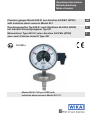
Operating Instructions Betriebsanleitung Mode d'emploi Pressure gauges Model 632.51 per directive 94/9/EC (ATEX) with inductive alarm sensors Model 831 GB Druckmessgeräte Typ 632.51 nach Richtlinie 94/9/EG (ATEX) mit Induktiv-Grenzsignalgeber Typ 831 D Manomètres Type 632.51 selon directive 94/9/EG (ATEX) avec seuil d‘alarme inductif Type 831 F II 2 GD c Model 632.51.160 per ATEX with inductive alarm sensors Model 831.12 GB Operating instructions Model 632.51 per ATEX with Model 831 Page 1 – 22 D Betriebsanleitung Typ 632.51 nach ATEX mit Typ 831 Seite 23 – 42 F Mode d'emploi Type 632.51 selon ATEX Page 43 – 49 11059738 11/2008 GB/D/F avec Type 831 Contents Contents 1. Safety instructions 4 2. Description 4 3. Technical data and intended use 5 4. Alarm contacts 7 5. Commissioning 9 6. Maintenance and servicing/cleaning 9 7. Repairs 9 8. Disposal 9 Enclosure 1: Declaration of conformity for Models 632.51 with inductive alarm sensors Model 831 10 Enclosure 2: EC-type examination certificate (Ex approval for gases) for slot-type initiators types SJ (WIKA-Model 831) 11 – 13 Enclosure 3: EC-type examination certificate (Ex approval for gases) for SN-sensors types SJ (WIKA-Model 831-SN/S1N) 14 – 17 11059738 11/2008 GB/D/F Enclosure 4: EC-type examination certificate (Ex approval for dust) for SN-proximity sensors types SJ (WIKA-Model 831 and 831-SN/S1N) 18 – 22 WIKA Operating instructions pressure gauges Model 632.51 with 831 per ATEX GB 1. Safety instructions / 2. Description ! 1. Safety instructions Caution GB The appropriate national safety regulations (i.e. VDE 0100/ EN 60 079-14/EN 837-2) must be observed when installing, putting into operation and running these instruments. n Do not work on gauge while under voltage nSerious injuries and/or damage can occur should the appropriate regulations not be observed nOnly appropriately qualified persons should work on these instruments 2. Description n The pressure gauges measure the pressure by means of resilient capsule measuring elements n The measuring features follow the example of the standards EN 837-3 and DIN 16 085 The built-in electrical alarm contacts are non-contact slot-type inductive proximity sensors, which are supplied from control units with circuits that are certified to be intrinsically safe. When the adjustable set points are reached, their output circuits will be opened or closed. nAs a standard slot sensors model 831 are used according to EC-type examination certificate PTB 99 ATEX 2219 X (see enclosure 2) and ZELM 03 ATEX 0128 X (see enclosure 4) nSN sensors models 831-SN and -S1N according to PTB 00 ATEX 2049 X (see enclosure 3) and ZELM 03 ATEX 0128 X (see enclosure 4) are special designs with safety features (that are not relevant to explosion protection) for special applications 11059738 11/2008 GB/D/F The connection values of the switches are in accordance with EN 60 947-5-6 (“NAMUR”). WIKA Operating instructions pressure gauges Model 632.51 with 831 per ATEX 3. Technical data and intended use 3. Technical data and intended use Working pressure Steady: full scale value Fluctuating: 0.9 x full scale value Overpressure safety: 50 x scale range 7 bar maximum GB Pressure connection nAccording to the general technical regulations for pressure gauges, respectively (i.e. EN 837-2 “Selection and installation recommendations for pressure gauges”). When screw-fitting the gauges the force required for sealing must not be applied through the case or terminal box but, using a suitable tool, only through the spanner flats provided for this purpose at the square of the connector. Installation using a spanner Temperature effect When the temperature of the measuring system deviates from the reference temperature (+20 °C): max. ±0.6 %/10 K of full scale value IP Ingress protection 11059738 11/2008 GB/D/F IP 54 per EN 60 529 / IEC 60 529 WIKA Operating instructions pressure gauges Model 632.51 with 831 per ATEX 3. Technical data and intended use Operating Temperature Ambient: -20 … +60 °C Attention: Footnote 1) under table 1 must be absolutely taken into account! GB Medium: see table 1 Attention! With gaseous substances the temperature may increase as a result of the compression temperature. In such cases the pressure change rate has to be slowed down resp. the permissible medium temperature has to be reduced. Table 1: Permissible medium temperature (only mechanical part) Ignition temperature of the ambient atmosphere (temperature class) > 85 °C (T 6) > 100 °C (T 5) > 135 °C (T 4) >200 °C (T 3) > 300 °C (T 2) > 450 °C (T 1) Permissible maximum medium temperature (in the pressure system) +70 °C +80 °C +80 °C +80 °C +80 °C +80 °C 1) The permissible uppper ambient temperature for the electrical components is determined by the electrical connection values and the ignition temperature of the ambient gases, vapours and dusts. Therefore the maximum permissible ambient temperatures specified in the EC-type examination certificates for slot-type sensors and SN sensors must be observed as well. The lower of these two values is to be considered the maximum permissible ambient temperature! Materials (wetted parts) 11059738 11/2008 GB/D/F Pressure connection with pressure chamber: Stainless steel Pressure element (capsule element): Stainless steel Sealing ring between socket and capsule element: PTFE WIKA Operating instructions pressure gauges Model 632.51 with 831 per ATEX 3. Technical data … / 4. Alarm contacts Installation nNominal position per EN 837-3 / 9.6.6 Figure 7: 90° ( ) nPressure connection: lower mount (LM) GB nIn order to avoid any additional heating, the instruments must not be exposed to direct solar irradiation while in operation! Permissible vibratory stress at the mounting location nAs a matter of principle the instruments should only be mounted at locations without vibratory stresses nWhere required, a decoupling from the mounting location can be achieved e.g. by a flexible connecting line from the measuring point to the pressure gauge and mounting via a measuring instrument bracket. 4. Alarm contacts EC-type examination certificates n Standard version Model 831.XX PTB 99 ATEX 2219 X (enclosure 2) and ZELM 03 ATEX 0128 X (enclosure 4) Depending on the number of switches and on the case diameter either Model SJ2-N … or Model SJ3.5- … -N … is used. n Safety pattern version Models 831.XX-SN or -S1N PTB 00 ATEX 2049 X (enclosure 3) and ZELM 03 ATEX 0128 X (enclosure 4) Depending on the number of switches and on the case diameter either Models SJ 2-SN …, SJ 2-S1N …, SJ 3.5-SN … or SJ 3.5-S1N … are used. The built-in sensor type is stated on the product label of the pressure gauge. Wiring details n The electrical connections should be made by qualified electricians 11059738 11/2008 GB/D/F n Connection of the switches via screw terminals in the terminal box n Conductor cross section max. 1.5 mm2 nThe terminal assignment is stated on the connection plate at the pressure gauge n The instruments are to be included in the equipotential bonding of the plant WIKA Operating instructions pressure gauges Model 632.51 with 831 per ATEX 4. Alarm contacts The permissible limits for Ui, Ii and Pi of the intrinsically safe supply circuits depend on the sensor type. They can be taken from the corresponding ECtype examination certificates. (The sensor type is stated on the connection plate of the pressure gauge.) GB Suitable switch amplifiers are e.g.: Circuit Sensor type Model designation Fa. Pepperl & Fuchs EC-type exami- nation certificate WIKAModel standard standard standard standard SN-sensors SN-sensors PTB 00 ATEX 2080 PTB 00 ATEX 2080 PTB 00 ATEX 2081 PTB 00 ATEX 2081 PTB 00 ATEX 2042 PTB 00 ATEX 2043 904.31 904.32 904.28 904.29 904.33 904.30 (s. Ex-certific.) Model 1 Model 2 KFD2-SR2-Ex1 KFD2-SR2 Ex2 KFA6-SR2-Ex1 KFA6-SR2-Ex2 KFD2-SH-Ex1 KHA6-SH-Ex1 Electromagnetic compatibility EMC according to EN 60 947-5-2. The instruments are to be protected against strong electromagnetic fields. To adjust red set pointers Red set pointers Adjustment lock Adjustment key removable The red set pointers for the alarm contacts are adjustable over the full range of the instrument. Switching points shall be set in the ranges between 10 % and 90 % of the scale, to ensure switching accuracy and long life of the mechanical measuring system. WIKA Operating instructions pressure gauges Model 632.51 with 831 per ATEX 11059738 11/2008 GB/D/F The red set pointers for the alarm contacts are adjustable over the adjustment lock in the window with the aid of adjustment key (included in delivery; to be found on standard gauges on the outside edge of the junction box). 5. Commissioning … 8. Disposal 5. Commissioning During the commissioning process pressure peaks must be absolutely avoided. Open the shut-off valves slowly. GB 6. Maintenance and servicing/cleaning The instruments require no maintenance or servicing. The indicator and switching function should be checked once or twice every 12 months. The instrument must be disconnected from the process to check with a pressure testing device. The instruments should be cleaned with a damp cloth moistened with soap solution. For cleaning the instruments should be disconnected from the mains power supply. It must be ensured that all the parts are dry before the power is switched on again. Remainder of the pressure medium in dismounted pressure gauges may be hazardous or toxic. This should be considered when handling and storing the removed pressure gauges. 7. Repairs Repairs are to be only carried out by the manufacturer or appropriately trained personnel. For further details see WIKA data sheet AC 08.01 or the data sheet for the respective basic gauge. 8. Disposal 11059738 11/2008 GB/D/F Dispose of instrument components and packaging materials in accordance with the respective waste treatment and disposal regulations of the region or country to which the instrument is supplied. WIKA Operating instructions pressure gauges Model 632.51 with 831 per ATEX Enclosure 1: 11059738 11/2008 GB/D/F GB 10 WIKA Operating instructions pressure gauges Model 632.51 with 831 per ATEX Enclosure 2: 11059738 11/2008 GB/D/F GB WIKA Operating instructions pressure gauges Model 632.51 with 831 per ATEX 11 Enclosure 2: 11059738 11/2008 GB/D/F GB 12 WIKA Operating instructions pressure gauges Model 632.51 with 831 per ATEX Enclosure 2: 11059738 11/2008 GB/D/F GB WIKA Operating instructions pressure gauges Model 632.51 with 831 per ATEX 13 Enclosure 3: 11059738 11/2008 GB/D/F GB 14 WIKA Operating instructions pressure gauges Model 632.51 with 831 per ATEX Enclosure 3: 11059738 11/2008 GB/D/F GB WIKA Operating instructions pressure gauges Model 632.51 with 831 per ATEX 15 Enclosure 3: 11059738 11/2008 GB/D/F GB 16 WIKA Operating instructions pressure gauges Model 632.51 with 831 per ATEX Enclosure 3: 11059738 11/2008 GB/D/F GB WIKA Operating instructions pressure gauges Model 632.51 with 831 per ATEX 17 Enclosure 4: 11059738 11/2008 GB/D/F GB 18 WIKA Operating instructions pressure gauges Model 632.51 with 831 per ATEX Enclosure 4: 11059738 11/2008 GB/D/F GB WIKA Operating instructions pressure gauges Model 632.51 with 831 per ATEX 19 Enclosure 4: 11059738 11/2008 GB/D/F GB 20 WIKA Operating instructions pressure gauges Model 632.51 with 831 per ATEX Enclosure 4: 11059738 11/2008 GB/D/F GB WIKA Operating instructions pressure gauges Model 632.51 with 831 per ATEX 21 Enclosure 4: 11059738 11/2008 GB/D/F GB 22 WIKA Operating instructions pressure gauges Model 632.51 with 831 per ATEX Inhalt Inhalt 1. Sicherheitshinweise 24 2. Beschreibung 24 3. Technische Daten und bestimmungsgemäße Verwendung 25 4. Elektrische Grenzsignalgeber 27 5. Inbetriebnahme 29 6. Wartung/Reinigung 29 7. Reparaturen 29 8. Entsorgung 29 Anlage 1: Konformitätserklärung für Typen 632.51 mit Grenzsignalgeber Typ 831 30 Anlage 2: EG-Baumusterprüfbescheinigung (Ex-Zulassung für Gase) für Schlitzinitiatoren Typen SJ (WIKA-Typ 831) 31 – 33 Anlage 3: EG-Baumusterprüfbescheinigung (Ex-Zulassung für Gase) für SN-Sensoren Typen SJ (WIKA-Typ 831-SN/S1N) 34 – 37 11059738 11/2008 GB/D/F Anlage 4: EG-Baumusterprüfbescheinigung (Ex-Zulassung für Stäube) für Näherungssensoren Typen SJ (WIKA-Typ 831 und 831-SN/S1N) 38 – 42 WIKA Betriebsanleitung Druckmessgeräte Typ 632.51 mit 831 nach ATEX 23 D 1. Sicherheitshinweise / 2. Beschreibung ! Vorsicht 1. Sicherheitshinweise Beachten Sie unbedingt bei Montage, Inbetriebnahme und Betrieb dieser Geräte die entsprechenden nationalen Sicherheitsvorschriften (z.B. VDE 0100/EN 60 079-14/EN 837-2). n Alle Arbeiten dürfen nur im spannungslosen Zustand erfolgen D nBei Nichtbeachten der entsprechenden Vorschriften können schwere Körperverletzungen und/oder Sachschäden auftreten nNur entsprechend qualifiziertes Personal darf an diesen Geräten arbeiten 2. Beschreibung nDie Geräte erfassen den zu messenden Druck mit elastischen Kapselfeder- Messgliedern n Die messtechnischen Eigenschaften entsprechen den Normen EN 837-3 und DIN 16 085 Die eingebauten elektrischen Grenzwertschalter sind berührungslos arbeitende, induktive Näherungsschalter in Schlitzbauform, die aus Trennschaltverstärkern mit bescheinigten eigensicheren Stromkreisen versorgt werden. Bei Überschreiten der einstellbaren Grenzwerte werden deren Ausgangsstromkreise geöffnet bzw. geschlossen. nStandard sind die Schlitzinitiatoren Typ 831 entsprechend der EG-Baumusterprüfbescheinigung PTB 99 ATEX 2219 X (siehe Anlage 2) und ZELM 03 ATEX 0128 X (siehe Anlage 4) nDie SN-Sensoren Typ 831-SN bzw. -S1N nach PTB 00 ATEX 2049 X (siehe Anlage 3) und ZELM 03 ATEX 0128 X (siehe Anlage 4) sind eine Sonderausführung mit (nicht den Explosionsschutz betreffenden) Sicherheitsmerkmalen für spezielle Anwendungen 11059738 11/2008 GB/D/F Die Anschlusswerte der Schalter entsprechen der EN 60 947-5-6 („NAMUR“). 24 WIKA Betriebsanleitung Druckmessgeräte Typ 632.51 mit 831 nach ATEX 3. Technische Daten und bestimmungsgemäße Verwendung 3. Technische Daten und bestimmungsgemäße Verwendung Verwendungsbereiche Ruhebelastung: Wechselbelastung: Überlastbarkeit: Skalenendwert 0,9 × Skalenendwert 50 x Skalenendwert, max. jedoch 7 bar D Druckanschluss nEntsprechend den allgemeinen technischen Regeln für Druckmessgeräte (z. B. EN 837-2 „Auswahl- und Einbauempfehlungen für Druckmessgeräte“). Beim Einschrauben der Geräte darf die zum Abdichten erforderliche Kraft nicht über das Gehäuse oder die Kabelanschlussdose aufgebracht werden, sondern mit geeignetem Werkzeug nur über die dafür vorgesehenen Schlüsselflächen am Vierkant des Anschlusszapfens. Montage mit Gabelschlüssel Temperatureinfluss Bei Abweichung von der Referenztemperatur am Messsystem (+20 °C): max. ±0,6 %/10 K vom jeweiligen Skalenendwert IP-Schutzart 11059738 11/2008 GB/D/F IP 54 nach EN 60 529/IEC 60 529 WIKA Betriebsanleitung Druckmessgeräte Typ 632.51 mit 831 nach ATEX 25 3. Technische Daten und bestimmungsgemäße Verwendung Zulässige Temperaturen Umgebung: -20 … +60 °C Achtung! Unbedingt unter Tabelle 1 die Fußnote 1) berücksichtigen! Messstoff: siehe Tabelle 1 Achtung! Bei gasförmigen Stoffen kann sich die Temperatur durch Kompressionswärme erhöhen. In solchen Fällen muss ggf. die DruckänderungsD geschwindigkeit gedrosselt bzw. die zulässige Messstofftemperatur reduziert werden. Tabelle 1: Zulässige Messstofftemperatur (nur mechanischer Teil) Zündtemperatur der umgebenden Atmosphäre (Temperaturklasse) > 85 °C (T 6) > 100 °C (T 5) > 135 °C (T 4) >200 °C (T 3) > 300 °C (T 2) > 450 °C (T 1) Zulässige maximale Messstofftemperatur (im Messsystem) +70 °C +80 °C +80 °C +80 °C +80 °C +80 °C 1) Die zulässige obere Umgebungstemperatur für die elektrischen Bauteile wird durch die elektrischen Anschlusswerte und die Zündtemperatur der umgebenden Gase, Dämpfe bzw. Stäube bestimmt.Deshalb müssen die in den EG-Baumusterprüfbescheinigungen für die Schlitzinitiatoren bzw. SN-Sensoren angegebenen höchstzulässigen Umgebungstemperaturen ebenfalls beachtet werden. Der niedrigere der beiden Werte ist als maximal zulässige Umgebungstemperatur anzusetzen! Werkstoffe (messstoffberührte Teile) 11059738 11/2008 GB/D/F Druckanschluss mit Messkammer: CrNi-Stahl Messglied (Kapselfeder): CrNi-Stahl Dichtung zwischen Federträger und Kapselfeder: PTFE 26 WIKA Betriebsanleitung Druckmessgeräte Typ 632.51 mit 831 nach ATEX 3. Technische Daten …/4. Elektrische Grenzsignalgeber Installation nNennlage nach EN 837-3 / 9.6.6 Bild 7: 90° ( ) nDruckanschlusszapfen unten nUm zusätzliche Aufheizung zu vermeiden, dürfen die Geräte im Betrieb keiner direkten Sonneneinstrahlung ausgesetzt werden! D Zulässige Schwingungsbelastung am Einbauort nDie Geräte sollten grundsätzlich nur an Stellen ohne Schwingungsbelastung eingebaut werden nGegebenenfalls kann z. B. durch eine flexible Verbindungsleitung von der Messstelle zum Druckmessgerät und die Befestigung über eine Messgerätehalterung eine Entkopplung vom Einbauort erreicht werden. 4. Elektrische Grenzsignalgeber EG-Baumusterprüfbescheinigungen nStandardausführung Typen 831.XX PTB 99 ATEX 2219 X (Anlage 2) und ZELM 03 ATEX 0128 X (Anlage 4) Abhängig von der Anzahl der Schalter und vom Gehäusedurchmesser wird entweder der Typ SJ2-N … oder der Typ SJ3,5- … -N … eingesetzt. nSicherheitsausführung Typen 831.XX-SN oder -S1N PTB 00 ATEX 2049 X (Anlage 3) und ZELM 03 ATEX 0128 X (Anlage 4) Abhängig von der Schalterzahl und vom Gehäusedurchmesser werden entweder die Typen SJ 2-SN…, SJ 2-S1N…, SJ 3,5-SN … oder SJ 3,5-S1N… eingesetzt. Der eingebaute Sensortyp ist auf dem Typenschild des Druckmessgerätes angegeben. Elektrischer Anschluss n Der elektrische Anschluss darf nur durch qualifiziertes Personal erfolgen 11059738 11/2008 GB/D/F n Anschluss der Schalter über Schraubklemmen in der Kabeldose n Leitungsquerschnitt max. 1,5 mm2 n Klemmenbelegung auf Anschlussschild am Druckmessgerät n Die Geräte sind in den Potenzialausgleich der Anlage mit einzubeziehen WIKA Betriebsanleitung Druckmessgeräte Typ 632.51 mit 831 nach ATEX 27 4. Elektrische Grenzsignalgeber Die zulässigen Grenzwerte für Ui, Ii und Pi der eigensicheren Versorgungsstromkreise hängen vom Initiatortyp ab. Sie sind aus den jeweiligen EGBaumusterprüfbescheinigungen zu entnehmen. (Der Initiatortyp ist auf dem Anschlussschild des Druckmessgerätes angegeben.) Geeignete Trennschaltverstärker sind z. B.: Stromkreis (s. Ex-Schein) Sensortyp Typenbezeichnung Fa. Pepperl & Fuchs EG-Baumuster- prüfbescheinigung WIKATyp Typ 1 Typ 2 KFD2-SR2-Ex1 KFD2-SR2 Ex2 KFA6-SR2-Ex1 KFA6-SR2-Ex2 KFD2-SH-Ex1 KHA6-SH-Ex1 PTB 00 ATEX 2080 PTB 00 ATEX 2080 PTB 00 ATEX 2081 PTB 00 ATEX 2081 PTB 00 ATEX 2042 PTB 00 ATEX 2043 904.31 904.32 904.28 904.29 904.33 904.30 Standard Standard Standard Standard SN-Sensoren SN-Sensoren Elektromagnetische Verträglichkeit EMV gemäß EN 60 947-5-2. Die Geräte sind vor starken elektromagnetischen Feldern zu schützen. Einstellen der Sollwertzeiger Das Einstellen der Sollwerte erfolgt über das Verstellschloss in der Sichtscheibe mit Hilfe des Verstellschlüssels (gehört zum Lieferumfang; befindet sich bei Standardgeräten seitlich an der Kabeldose). Sollwertzeiger abnehmbarer Verstellschlüssel Verstellschloss 28 Die Sollwertzeiger der Grenzwertschalter sind im gesamten Skalenbereich frei einstellbar. Aus Gründen der Schaltgenauigkeit und der Lebensdauer der mechanischen Messsysteme sollen die Schaltpunkte zwischen 10 % und 90 % der Messspanne liegen. WIKA Betriebsanleitung Druckmessgeräte Typ 632.51 mit 831 nach ATEX 11059738 11/2008 GB/D/F D 5. Inbetriebnahme … 8. Entsorgung 5. Inbetriebnahme Bei Inbetriebnahme Druckstöße unbedingt vermeiden, Absperrventile langsam öffnen. 6. Wartung/Reinigung Die Geräte sind wartungsfrei. Eine Überprüfung der Anzeige und der Schaltfunktion sollte etwa 1 bis 2 mal pro Jahr erfolgen. Dazu ist das Gerät vom Prozess zu trennen und mit einer Druckprüfvorrichtung zu kontrollieren. Reinigen der Geräte mit einem (in Seifenlauge) angefeuchteten Tuch. Zur Reinigung sind die Geräte vom Netz zu trennen. Vor Wiedereinschalten des Stromes ist sicherzustellen, dass alle Teile abgetrocknet sind. Messstoffreste in ausgebauten Druckmessgeräten können zur Gefährdung von Menschen, Umwelt und Einrichtung führen. Ausreichende Vorsichtsmaßnahmen sind zu ergreifen. 7. Reparaturen Reparaturen sind ausschließlich vom Hersteller oder entsprechend geschultem Personal durchzuführen. Weitere technische Daten bitte dem WIKA Datenblatt AC 08.01 bzw. dem Datenblatt des jeweiligen Grundgerätes entnehmen. 8. Entsorgung 11059738 11/2008 GB/D/F Entsorgen Sie Gerätekomponenten und Verpackungsmaterialien entsprechend den einschlägigen landesspezifischen Abfallbehandlungs- und Entsorgungsvorschriften des Anliefergebietes. WIKA Betriebsanleitung Druckmessgeräte Typ 632.51 mit 831 nach ATEX 29 D Anlage 1: 11059738 11/2008 GB/D/F D 30 WIKA Betriebsanleitung Druckmessgeräte Typ 632.51 mit 831 nach ATEX Anlage 2: 11059738 11/2008 GB/D/F D WIKA Betriebsanleitung Druckmessgeräte Typ 632.51 mit 831 nach ATEX 31 Anlage 2: 11059738 11/2008 GB/D/F D 32 WIKA Betriebsanleitung Druckmessgeräte Typ 632.51 mit 831 nach ATEX Anlage 2: 11059738 11/2008 GB/D/F D WIKA Betriebsanleitung Druckmessgeräte Typ 632.51 mit 831 nach ATEX 33 Anlage 3: 11059738 11/2008 GB/D/F D 34 WIKA Betriebsanleitung Druckmessgeräte Typ 632.51 mit 831 nach ATEX Anlage 3: 11059738 11/2008 GB/D/F D WIKA Betriebsanleitung Druckmessgeräte Typ 632.51 mit 831 nach ATEX 35 Anlage 3: 11059738 11/2008 GB/D/F D 36 WIKA Betriebsanleitung Druckmessgeräte Typ 632.51 mit 831 nach ATEX Anlage 3: 11059738 11/2008 GB/D/F D WIKA Betriebsanleitung Druckmessgeräte Typ 632.51 mit 831 nach ATEX 37 Anlage 4: 11059738 11/2008 GB/D/F D 38 WIKA Betriebsanleitung Druckmessgeräte Typ 632.51 mit 831 nach ATEX Anlage 4: 11059738 11/2008 GB/D/F D WIKA Betriebsanleitung Druckmessgeräte Typ 632.51 mit 831 nach ATEX 39 Anlage 4: 11059738 11/2008 GB/D/F D 40 WIKA Betriebsanleitung Druckmessgeräte Typ 632.51 mit 831 nach ATEX Anlage 4: 11059738 11/2008 GB/D/F D WIKA Betriebsanleitung Druckmessgeräte Typ 632.51 mit 831 nach ATEX 41 Anlage 4: 11059738 11/2008 GB/D/F D 42 WIKA Betriebsanleitung Druckmessgeräte Typ 632.51 mit 831 nach ATEX Sommaire Sommaire 1. Conseils de sécurité 44 2. Description 44 3. Caractéristiques techniques et utilisation correspondante 45 4. Contacts électriques 47 5. Mise en service 49 6. Maintenance/nettoyage 49 7. Réparations 49 8. Mise au rebus 49 Déclaration de Conformité des types 632.51 avec contact électrique type 831 (allemand/anglais) 30 Attestation d’examen CE (homologation Ex pour gaz) pour détecteurs de proximité à fente des types SJ anglais 11 – 13 (WIKA-type 831) allemand 31 – 33 Attestation d’examen CE (homologation Ex pour gaz) pour détecteurs SN des types SJ anglais (WIKA-type 831-SN/S1N) allemand 14 – 17 34 – 37 11059738 11/2008 GB/D/F Attestation d’examen CE (homologation Ex pour poussières) pour détecteurs de proximité à fente des types SJ anglais 18 – 22 (WIKA-type 831 et 831-SN/S1N) allemand 38 – 42 WIKA Mode d'emploi manomètres Type 632.51 avec 831 selon ATEX 43 F 1. Conseils de sécurité / 2. Description ! Avertissement 1. Conseils de sécurité Les prescriptions de sécurité nationales en vigueur (par exemple VDE 0100/EN 60 079-14/EN 837-2) doivent absolument être respectées lors du montage, de la mise en service et de l’utilisation des instruments ici présentés. n Toutes les interventions doivent être effectuées hors tension nLe non-respect des instructions correspondantes est susceptible d’entraîner des risques de blessure et/ou des dégâts matériels F nSeul le personnel habilité et qualifié est autorisé à manipuler les instruments 2. Description n Les appareils mesurent la pression par le biais d’un capsule manométrique à déformation élastique. n Les caractéristiques techniques de mesure suivent l‘exemple des normes EN 837-3 et DIN 16 085 Les seuils d’alarme électriques intégrés sont des détecteurs de proximité travaillant sans contact mécanique en forme d’entrefer. Ils sont alimentés par des relais amplificateurs homologués pour circuits en sécurité intrinsèque. Lors du dépassement des seuils réglables, les circuits de sortie s’ouvrent ou se ferment. nLes détecteurs inductifs standard du type 831 correspondent aux procédures d’attestation de la conformité PTB 99 ATEX 2219 X (voir annexe 2) et ZELM 03 ATEX 0128 X (voir annexe 4) Les valeurs de branchement des contacts correspondent à la EN 60 9475-6 («NAMUR»). 44 WIKA Mode d'emploi manomètres Type 632.51 avec 831 selon ATEX 11059738 11/2008 GB/D/F nLes détecteurs SN type 831-SN ou -S1N selon PTB 00 ATEX 2049 X (voir annexe 3) et ZELM 03 ATEX 0128 X (voir annexe 4) sont une exécution spéciale (ne concernant pas la protection anti-explosion) avec des attributs de sécurité pour des utilisations spéciales. 3. Caractéristiques techniques et utilisation correspondante 3. Caractéristiques techniques et utilisation correspondante Etendues de mesure Charge statique: fin d‘échelle Charge dynamique: 0,9 x fin d‘échelle Limite de surcharge: 50 x fin d‘échelle, 7 bar maxi Raccord de pression nConformément aux règles techniques générales pour les manomètres (par exemple EN 837-2 «Recommandations sur le choix et l’installation des manomètres»). Lors de l’opération de vissage des appareils de mesure, la force nécessaire ne doit pas être appliquée sur le boîtier ou sur la prise câblée, mais seulement sur les surfaces prévues par un outil approprié sur le carré du raccord. Montage avec clé à fourche Influence de la température En cas de divergence de la température de référence (+20 °C) sur l’organe moteur: max. ±0,6 %/10 K de la valeur d’échelle finale respective IP Degré de protection 11059738 11/2008 GB/D/F IP 54 selon EN 60 529 / IEC 60 529 WIKA Mode d'emploi manomètres Type 632.51 avec 831 selon ATEX 45 F 3. Caractéristiques techniques et utilisation correspondante Températures autorisées Ambiante: -20 … +60 °C Attention! Absolument prendre en considération la note de bas de page 1) en dessous du tableau 1. Fluide: voir tableau 1 Attention! Pour les fluides gazeux la température peut s’élever par le biais d’une température de compression. Dans ces cas il faut, soit limiter la vitesse d’élévation de la pression, soit réduire la température de fluide admissible. F Tableau 1: Température de fluide admissible (uniquement pour la partie mécanique) Température d’inflammation de l’atmosphère environnante (Classe de température) Température maximale autorisée du fluide (dans le système de mesure) > 85 °C (T 6) > 100 °C (T 5) > 135 °C (T 4) >200 °C (T 3) > 300 °C (T 2) > 450 °C (T 1) +70 °C +80 °C +80 °C +80 °C +80 °C +80 °C 1) L a valeur supérieure de la température ambiante admissible pour les composants électriques est déterminée par les valeurs électriques de branchement et la température d’inflammation des gaz, vapeurs ou poussières environnants. Par conséquent, il faut respecter également les valeurs de températures ambiantes maximales pour les détecteurs à entrefer ou détecteurs SN comme décrits dans les procédures d’attestation de la conformité CE. La valeur la plus basse des deux est à utiliser comme température ambiante maximale admissible! Matériaux (parties en contact avec le fluide) 11059738 11/2008 GB/D/F Cellule de mesure et raccord: acier inox Organe moteur (capsule): acier inox Joint entre raccord et capsule: PTFE 46 WIKA Mode d'emploi manomètres Type 632.51 avec 831 selon ATEX 3. Caractéristiques techniques … /4. Contacts électriques Installation nPosition de base selon EN 837-3 / 9.6.6. image 7: 90° ( ) nRaccord pression vertical nAfin d‘éviter un échauffement additionnel en fonctionnement, les appareils ne doivent pas être exposés aux rayons solaires! Contrainte de vibration admissible sur le point de montage nLes appareils ne devraient en principe être installés que sur des applications exemptes de vibrations nLe cas échéant, on peut atteindre un découplage du point de mesure en utilisant une liaison flexible au manomètre et en le fixant à l’aide d’un support d’appareil mural. 4. Contacts électriques Attestation d’examen CE nExécution standard types 831.XX PTB 99 ATEX 2219 X (annexe 2) et ZELM 03 ATEX 0128 X (annexe 4) En fonction du nombre de contacts et du diamètre du boîtier on utilise soit le type SJ2-N …, soit le type SJ3,5- … -N nExécution de sécurité types 831.XX-SN ou -S1N PTB 00 ATEX 2049 X (annexe 3) et ZELM 03 ATEX 0128 X (annexe 4) En fonction du nombre de contacts et du diamètre du boîtier on utilise soit les types SJ 2-SN … , SJ 2-S1N … , SJ 3,5-SN … , soit SJ 3,5-S1N … Le type de détecteur intégré est indiqué sur la plaquette d’identification du manomètre. Raccords électriques nLes travaux de raccordement électrique ne doivent être effectués que par des ouvriers qualifiés pour ce faire 11059738 11/2008 GB/D/F n Le branchement des contacts se fait bar des bornes dans la boîte de jonction. n La section des conducteurs est de maxi 1,5 mm2 nLa codification des borniers se trouve sur la plaquette de branchement de l’appareil n Les appareils sont à inclure dans la compensation de potentiel de l’installation WIKA Mode d'emploi manomètres Type 632.51 avec 831 selon ATEX 47 F 4. Contacts électriques Les valeurs limites autorisées pour Ui, li et Pi de l’alimentation intrinsèque des circuits dépendent du type de détecteur. Ces valeurs sont indiquées dans les procédures d’attestation de la conformité CE. (Le type de détecteur est indiqué sur le schéma de branchement du manomètre). Exemple pour relais d’amplification appropriés: Circuit Type de détecteur Code de désignation Etbs. Pepperl & Fuchs Attestation d’examen CE Type WIKA Type 1 Type 2 Standard Standard Standard Standard SN-Sensoren SN-Sensoren KFD2-SR2-Ex1 KFD2-SR2 Ex2 KFA6-SR2-Ex1 KFA6-SR2-Ex2 KFD2-SH-Ex1 KHA6-SH-Ex1 PTB 00 ATEX 2080 PTB 00 ATEX 2080 PTB 00 ATEX 2081 PTB 00 ATEX 2081 PTB 00 ATEX 2042 PTB 00 ATEX 2043 904.31 904.32 904.28 904.29 904.33 904.30 Compatibilité électromagnétique CEM selon EN 60 947-5-2. Les appareils sont à protéger contre de forts champs électromagnétiques. Réglage de l’indicateur de la valeur de consigne Le réglage des valeurs de consigne s’effectue au moyen via le trou de réglage dans le cadran à l’aide de la clef de réglage (fournie avec l’appareil, elle se trouve, dans les modèles standard, sur le côté dans la boîte à câble). Indicateur de la valeur de consigne Trou de réglage 48 Clef de réglage amovible Les indicateurs de valeur de consigne des seuils peuvent être réglés librement sur toute l‘échelle de mesure. Pour des raisons de précision et de sécurité de commutation, et afin de ne pas porter préjudice à la durée de vie des appareils, il est recommander de fixer les points de commutation entre 10 % et 90 % de l‘écart de mesure. WIKA Mode d'emploi manomètres Type 632.51 avec 831 selon ATEX 11059738 11/2008 GB/D/F F (voir fiche Ex) 5. Mise en service … 8. Mise au rebus 5. Mise en service Lors de la mise en service il faut absolument éviter les coups de bélier. Ouvrir lentement les vannes de fermeture. 6. Maintenance/Nettoyage Les instruments ne requièrent aucune maintenance. Un contrôle de l’affichage et des fonctions de commande est recommandé 1 à 2 fois/an. Pour le contrôle de l’affichage et des fonctions de commande, il faut F isoler l’appareil du processus de mesure et le contrôler avec un dispositif de contrôle de pression. Nettoyer les instruments avec un légèrement humidifié avec une lessive (de savon). Avant de procéder au nettoyage, débrancher l'instrument du réseau. Avant de rebrancher l'instrument, s'assurer que toutes les pièces sont entièrement sèches. Des restes de fluide se trouvant dans les manomètres démontés peuvent provoquer une mise en danger de personnes, de l’environnement et de l’équipement. Des précautions adéquates sont à prendre. 7. Réparations Toute réparation doit être exclusivement confiée au fabricant ou au personnel qualifié correspondant. Pour autres données, se reporter à la fiche type WIKA AC 08.01 ou à la fiche technique de l’instrument correspondant. 8. Mise au rebus 11059738 11/2008 GB/D/F Mettez les composants des appareils et les emballages au rebus en respectant les prescriptions nationales pour le traitement et la mise au rebus des régions de livraison. WIKA Mode d'emploi manomètres Type 632.51 avec 831 selon ATEX 49 WIKA Global Austria WIKA Messgerätevertrieb Ursula Wiegand GmbH & Co. KG 1230 Vienna Phone:(+43) 1-86 91 631 Fax: (+43) 1-86 91 634 E-mail: [email protected] www.wika.at Benelux WIKA Benelux 6101 WX Echt Phone:(+31) 475-535 500 Fax: (+31) 475-535 446 E-mail: [email protected] www.wika.nl Bulgaria WIKA Bulgaria EOOD 1309 Sofia Phone:(+359) 2 82138-10 Fax: (+359) 2 82138-13 E-mail: [email protected] Germany WIKA Alexander Wiegand GmbH & Co. KG 63911 Klingenberg Phone:(+49) 93 72-13 20 Fax: (+49) 93 72-13 24 06 E-mail: [email protected] www.wika.de Italy WIKA Italiana SRL 20020 Arese (Milano) Phone:(+39) 02-93 86 11 Fax: (+39) 02-93 86 174 E-mail: [email protected] www.wika.it Poland WIKA Polska S.A. 87-800 Wloclawek Phone:(+48) 542 30 11 00 Fax: (+48) 542 30 11 01 E-mail: [email protected] www.wikapolska.pl Croatia WIKA Croatia d.o.o. Hrastovička 19 10250 Zagreb-Lučko Phone:(+385) 1 6531034 Fax: (+385) 1 6531357 E-mail: [email protected] Romania WIKA Instruments Romania S.R.L. Bucuresti, Sector 5 Calea Rahovei Nr. 266-268 Corp 61, Etaj 1 Phone:(+40) 21 4563138 Fax: (+40) 21 4563137 E-mail: [email protected] Finland WIKA Finland Oy 00210 Helsinki Phone:(+358) 9-682 49 20 Fax: (+358) 9-682 49 270 E-mail: [email protected] www.wika.fi Russia ZAO „WIKA Mera“ 127015 Moscow Phone:(+7) 495-648 01 80 Fax: (+7) 495-648 01 81 E-mail: [email protected] www.wika.ru France WIKA Instruments s.a.r.l. 95610 Eragny-sur-Oise Phone:(+33) 1-34 30 84 84 Fax: (+33) 1-34 30 84 94 E-mail: [email protected] www.wika.fr Serbia WIKA Merna Tehnika d.o.o. Sime Solaje 15 11060 Belgrade Phone:(+381) 11 27 63 722 Fax: (+381) 11 75 36 74 E-mail: [email protected] www.wika.co.yu 50 Spain Instrumentos WIKA, S.A. C/Josep Carner, 11-17 08205 Sabadell (Barcelona) Phone:(+34) 902 902 577 Fax: (+34) 933 938 666 E-mail: [email protected] www.wika.es Switzerland Manometer AG 6285 Hitzkirch Phone:(+41) 41-919 72 72 Fax: (+41) 41-919 72 73 E-mail: [email protected] www.manometer.ch Turkey WIKA Alexander Wiegand GmbH & Co. KG Türkiye (Istanbul) irtibat bürosu Zümrütevler Mah. Hanimeli Cad. No. 4 Kat: 4 Maltepe - Istanbul Phone:(+90) 216/305 46 24 Fax: (+90) 216/305 36 19 E-mail: [email protected] www.wika.com.tr Ukraine WIKA Pribor GmbH 83016 Donetsk Phone:(+38) 062 345 34 16 Fax: (+38) 062 345 34 17 E-mail: [email protected] www.wika.ua United Kingdom WIKA Instruments Ltd Merstham, Redhill RH13LG Phone:(+44) (0) 1737 644 008 Fax: (+44) (0) 1737 644 403 E-mail: [email protected] www.wika.co.uk WIKA Betriebsanleitung Druckmessgeräte Typ 632.51 mit 831 nach ATEX 11059738 11/2008 GB/D/F Europe WIKA Global North America Canada WIKA Instruments Ltd. Head Office Edmonton, Alberta, T6N 1C8 Phone:(+1) 780-463 70 35 Fax: (+1) 780-462 00 17 E-mail: [email protected] www.wika.ca Mexico Instrumentos WIKA Mexico S.A. de C.V. 01210 Mexico D.F. Phone: (+52) 555 020 53 00 Fax: (+52) 555 020 53 01 E-mail: [email protected] www.wika.com.mx USA WIKA Instrument Corporation Lawrenceville, GA 30043 Phone:(+1) 770-513 82 00 Fax: (+1) 770-338 51 18 E-mail: [email protected] www.wika.com South America Argentina WIKA Argentina S.A. Buenos Aires Phone:(+54) 11-4730 18 00 Fax: (+54) 11-4761 00 50 E-mail: [email protected] www.wika.com.ar 11059738 11/2008 GB/D/F Brazil WIKA do Brasil Ind. e Com. Ltda. CEP 18560-000 Iperó - SP Phone:(+55) 15-3459 97 00 Fax: (+55) 15-3266 16 50 E-mail: [email protected] www.wika.com.br Africa / Middle East Egypt WIKA Alexander Wiegand GmbH & Co. KG El-Serag City Towers Tower #2, Office#67 Nasr City, Cairo Phone:(+20) 2 2287 6219 Fax: (+20) 2 2273 3140 E-mail: [email protected] South Africa WIKA Instruments (Pty.) Ltd. Gardenview, Johannesburg 2047 Phone:(+27) 11-621 00 00 Fax: (+27) 11-621 00 59 E-mail: [email protected] www.wika.co.za United Arab Emirates WIKA Middle East FZE Jebel Ali, Dubai Phone:(+971) 4 - 883 90 90 Fax: (+971) 4 - 883 91 98 E-mail: [email protected] Asia China WIKA International Trading (Shanghai) Co., Ltd. 200001 Shanghai Phone:(+86) 21 - 53 85 25 72 Fax: (+86) 21 - 53 85 25 75 E-mail: [email protected] India WIKA Instruments India Pvt. Ltd. Village Kesnand, Wagholi Pune - 412 207 Phone:(+91) 20 - 66 29 32 00 Fax: (+91) 20 - 66 29 33 25 E-mail: [email protected] www.wika.co.in Japan WIKA Japan K. K. Tokyo 105-0023 Phone:(+81) 3-54 39 66 73 Fax: (+81) 3-54 39 66 74 E-mail: [email protected] Kazakhstan TOO WIKA Kazakhstan 050050 Almaty Phone:(+7) 32 72 33 08 48 Fax: (+7) 32 72 78 99 05 E-mail: [email protected] Korea WIKA Korea Ltd. Seoul 153-023 Phone:(+82) 2 - 8 69 05 05 Fax: (+82) 2 - 8 69 05 25 E-mail: [email protected] Malaysia WIKA Instrumentation (M) Sdn. Bhd. 47100 Puchong, Selangor Phone:(+03) 80 63 10 80 Fax: (+03) 80 63 10 70 E-mail: [email protected] www.wika.com.my Singapore WIKA Instrumentation Pte. Ltd. 569625 Singapore Phone:(+65) 68 44 55 06 Fax: (+65) 68 44 55 07 E-mail: [email protected] www.wika.com.sg Taiwan WIKA Instrumentation Taiwan Ltd. Pinjen, Taoyuan Phone:(+886) 3 420 6052 Fax: (+886) 3 490 0080 E-mail: [email protected] www.wika.com.tw Australia Australia WIKA Australia Pty. Ltd. Rydalmere, NSW 2116 Phone:(+61) 2 - 88 45 52 22 Fax: (+61) 2 - 96 84 47 67 E-mail: [email protected] www.wika.com.au New Zealand Process Instruments Limited Unit 7 / 49 Sainsbury Road St Lukes - Auckland 1025 Phone:(+64) 9 - 847 90 20 Fax: (+64) 9 - 846 59 64 E-mail: [email protected] www.wika.co.nz WIKA Betriebsanleitung Druckmessgeräte Typ 632.51 mit 831 nach ATEX 51 WIKA Alexander Wiegand GmbH & Co. KG Alexander-Wiegand-Straße 30 63911 Klingenberg • Germany Phone (+49) 9372/132-0 Fax (+49) 9372/132-406 E-Mail [email protected] www.wika.de 52 11059738.02 11/2008 GB/D/F Technical alteration rights reserved. Technische Änderungen vorbehalten. Sous réserve de modifications techniques.