1
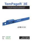
Room Alert 12E ® Temperature & Environment Monitoring... Made Easy! Phone Fax Web 401.628.1600 401.628.1601 AVTECH.com User’s Guide & Reference Manual 130401.01 Protect Your IT Facility... Don’t Wait Until It’s Too Late! Monitor, Alert... Log, Graph... View, Respond... Report, Plan! Install Room Alert & TemPageR... The Most Popular Physical Environment Monitors In The World! • • • • • • Digital Temperature Digital Outdoor Temperature Digital Fluid Temperature Digital Humidity Main / UPS Power Flood / Water • • • • • • Heat Index (Feels Like) Smoke / Fire Sound, Light Air Flow Motion, Room Entry Panic Buttons, Security • • • • • • Wireless Sensor Hubs Light Towers, Relay Switches Network Cameras Switch Sensors Dry Contacts Low Voltage Sensors The Most Advanced, Easy-To-Use, Reliable & Affordable Monitors Available. 888.220.6700 401.628.1600 AVTECH.com Environment Monitor.com On behalf of the entire team at AVTECH, we say, “Thank You!” It is our privilege to serve you, our valued customer. Copyright Information Copyright 1988-2013 AVTECH Software Inc. All Rights Reserved. No part of this book may be used or reproduced for commercial benefit in any form or by any means, or stored in a database or retrieval system, without prior written permission of AVTECH Software Inc., except in the case of brief quotations embodied in articles and reviews. Making copies of any part of this book for any purpose other than your individual use is a violation of United States copyright laws and international treaty provisions. For information or additional copies, contact AVTECH Software Inc., as directed below. Printed in the United States of America. Warning and Disclaimer This publication is shipped as is, without warranty of any kind, either express or implied. While every precaution has been taken in the preparation of this publication, the publisher and authors assume no responsibility for errors or omissions. Neither is any liability assumed for damages resulting from the use of the information or instructions contained herein. It is further stated that the publisher and authors are not responsible for any damage or loss to your data or equipment that may result directly or indirectly from your use of this publication and the related hardware & software. Nothing in the AVTECH firmware, software, SNMP Mibs, documentation or online resources shall be construed as conferring any license under any of the AVTECH Software (AVTECH) or any third party’s intellectual property rights, whether by estoppel, implication, or otherwise. Trademark Acknowledgements AVTECH, the AVTECH Logo, AVTECH Software, the AVTECH Manager Character, AVTECH.com, AVTECHSoftware.com, Device Discovery, Device ManageR, Environment Alarm, “Environment Monitoring Made Easy!”, EnvironmentMonitor.com, “IT Environment Monitoring Made Easy!”, Mini UPS, MUPS, “Network-Wide Monitoring Made Easy!”, “Protect Your IT Environment... Don’t Wait Until It’s Too Late!”, Room Alert, Room Alert PLUS, Room Alert Relay, Room Alert RPC, Room Alert Signal Tower, RoomAlert.com, “System Monitoring Made Easy!”, TemPageR, TemPageR.com, “Temperature & Environment Monitoring... Made Easy!”, “Temperature Monitoring Made Easy!”, Wireless Sensor Hub, Wireless Sensor Hub & Powered Relay, WiSH and WiSPR are trademarks or registered trademarks of AVTECH Software Inc. Any other trademarks, product or company names mentioned herein are the property of their respective owners and used strictly for the purpose of identifying compatibility. AVTECH Software Inc. cannot attest to the accuracy of any other organization’s ownership claim to a trademark and use of any trademark in this publication should not be regarded as affecting the validity of any trademark or service mark. Special Thanks We would like to recognize our customers, field test participants, reseller partners, inhouse sales & support staff, as well as the entire software & hardware development teams for their contributions and assistance in the completion of this manual. Sales, Support & Contact Information To receive further information or assistance regarding this publication, or any AVTECH product or service, please contact:. Headquarters AVTECH Software Inc.Email [email protected] 16 Cutler Street, Cutler Mill [email protected] Warren, RI 02885 USA [email protected] Phone 401.628.1600Web AVTECH.com Sales 888.220.6700EnvironmentMonitor.com RoomAlert.com Fax 401.628.1601TemPageR.com Room Alert 12E Table of Contents Introduction To Room Alert 12E .....................................................................................................3 Room Alert 12E Package Contents..................................................................................................4 The Room Alert 12E ID Box .....................................................................................................4 Front .....................................................................................................................................5 Back .....................................................................................................................................6 How To Install Your Room Alert 12E .............................................................................................7 Step 1: Connect Your Room Alert 12E Hardware....................................................................7 If Your Network Is Power Over Ethernet (PoE) Enabled....................................................7 If Your Network Is Not Power Over Ethernet (PoE) Enabled.............................................7 Step 2: Open And View Your Room Alert 12E In Your Web Browser ...................................8 With The Built-In Interface .................................................................................................8 With Device Manager For Advanced Functionality ............................................................8 Step 3: Install Additional Components .....................................................................................9 Connect Included External Sensors .....................................................................................9 Connect Other Compatible Components .............................................................................9 How To Use Room Alert 12E’s Web Interface .............................................................................10 Status ........................................................................................................................................10 Current Sensor Status Bar ..................................................................................................11 Sensor Display Area ..........................................................................................................12 Settings.....................................................................................................................................13 Network..............................................................................................................................14 SMTP Email.......................................................................................................................16 Simple Network Management Protocol (SNMP) ..............................................................19 Sensors ...............................................................................................................................21 Alarm Options ....................................................................................................................30 Security ..............................................................................................................................34 Advanced ...........................................................................................................................36 AVTECH Software, Inc. 1 Room Alert 12E Help ..........................................................................................................................................41 About........................................................................................................................................42 Updating & Troubleshooting Your Room Alert 12E ....................................................................43 How To Download Firmware & Software Updates From AVTECH.com ..............................43 How To Update Room Alert 12E’s Firmware .........................................................................43 How To Discover Room Alert 12E When Your Network Blocks UDP Broadcasts ...............44 How To Reset Room Alert 12E To Factory Defaults ..............................................................44 Introduction To AVTECH’s Device ManageR .............................................................................46 2 AVTECH Software, Inc. Room Alert 12E Introduction To Room Alert 12E The Room Alert 12E is AVTECH’s mid-sized monitor that has something for everyone. It boasts all the features of our highest-end unit on a smaller scale and at a lower price. With the Room Alert 12E, AVTECH brings you Temperature & Facilities Environment Monitoring… Made Easy. The Room Alert 12E has one (1) internal temperature sensor and ten (10) external ports: three (3) external digital, four (4) external switch, one (1) relay output, one (1) analog input, and one (1) Light Tower & Relay Adapter port. Sensors are included for temperature and power. Install your unit with minimal planning and less hassle. 9 Get up and running in minutes with easy “Plug and Play” setup. 9 Use Power over Ethernet to install even where no DC power is available. 9 Mount Room Alert 12E in a rack, on a wall, ceiling or table top. Get access from anywhere over the web. 9 Configure, monitor and operate Room Alert 12E with its easy-to-use built-in web interface. 9 Significantly expand its functionality with AVTECH’s Device ManageR, the powerful software bundled FREE with all Room Alert monitors. 9 Have the flexibility to monitor with any SNMP-enabled 3rd-party monitoring application. Know immediately when physical conditions change. 9 Set alert thresholds for the built-in and bundled Digital Temperature Sensor from -40° to 185° F (-40° to 85° C). 9 Monitor the on/off status of a critical power source with the bundled external Power Sensor. 9 Alert multiple contacts on your team when thresholds are exceeded. 9 Receive alert notifications by email, email-to-SMS and more on a computer or mobile phone. Expand your options as your needs evolve. 9 Extend your reach by adding 2 more external digital sensors up to 100 feet away and 4 external switch sensors up to 900! 9 Monitor an analog sensor using the built-in analog input port. 9 Automatically turn on/off electrical devices, such as air conditioners or generators, by using the built-in relay output port and adding a Relay Switch Sensor (with adapter). 9 Use the Light Tower & Relay Adapter port to add a Light Tower or Relay Switch Sensor. 9 Explore your options further with your AVTECH Product Specialist. AVTECH Software, Inc. 3 Room Alert 12E Room Alert 12E Package Contents The standard Room Alert 12E package includes: • One (1) Room Alert 12E ID Box • One (1) External Digital Temperature & Humidty Sensor • One (1) External Power Sensor • One (1) 10' Ethernet Cable • One (1) Room Alert 12E User’s Guide & Reference Manual (You’re reading it now.) • One (1) Package Of Literature & Additional Information The Room Alert 12E ID Box Reset Button Power Port Ethernet Port Digital Ports (3) Front 4 Analog Input Port Light Tower/ Relay Port Relay Output Port Switch Sensor Ports (4) Back AVTECH Software, Inc. Room Alert 12E Front Power Port A standard power port connects Room Alert 12E to an electrical outlet with AVTECH’s International Power Adapter. NOTE Look for the AVTECH logo. Using another power adapter could damage the Room Alert 12E’s circuit board and void the warranty. If you need one, purchase it online at AVTECH.com. AVTECH has an international power adapter with a compatible plug style for each and every country. Ethernet Port An RJ-45 PoE-enabled port connects Room Alert 12E to your network via an RJ-45 network cable. Digital Sensor Ports Three (3) standard RJ-11 jacks connect any AVTECH digital sensor to your Room Alert 12E via a standard RJ-11 (straight through) telephone cord. Digital Sensor Port 1 is shown here. AVTECH Software, Inc. 5 Room Alert 12E Back Reset Button A small push button resets Room Alert 12E to factory default settings. Light Tower & Relay Adapter Port A standard RJ-11 jack connects a Light Tower & Relay Adapter to your Room Alert 12E via a standard RJ-11 (straight through) telephone cord. Relay Output Port A set of contacts connects any low-voltage device to your Room Alert 12E via standard speaker wire. Analog Input Port A set of contacts connects any low-voltage analog sensor to your Room Alert 12E via standard speaker wire. Switch Sensor Ports Four (4) sets of dry contacts connect Room Alert 12E to any AVTECH switch sensor or dry contact on a device (e.g., HVAC, generator, pump, fan, etc.) via standard speaker wire or low-voltage 2-wire cable. Switch Sensor Port 1 is shown here. NOTE For more information about AVTECH sensors and accessories, please refer to the Appendix at the back of this manual or visit the Sensors and Accessories sections of AVTECH.com. 6 AVTECH Software, Inc. Room Alert 12E How To Install Your Room Alert 12E Step 1: Connect Your Room Alert 12E Hardware If Your Network Is Power Over Ethernet (PoE) Enabled • Connect one end of a standard Ethernet cable to the Room Alert 12E’s Ethernet port. • Connect the other end to a PoE-enabled network jack. That’s it! Your Room Alert 12E is now powered and discoverable on your network. If Your Network Is Not Power Over Ethernet (PoE) Enabled A. Connect To Your Network First • Connect one end of a standard Ethernet cable to the Room Alert 12E’s Ethernet port. • Connect the other end to a network jack. B. Then Connect To A Power Source • Plug one end of AVTECH’s International Power Adapter into the Room Alert 12E’s power port. • Plug the other end into a surge-protected power source. A B Your Room Alert 12E is now powered and discoverable on your network! NOTE Use only AVTECH’s International Power Adapter. Others could damage the Room Alert 12E and void your warranty. If you don’t have one, please visit our online store at AVTECH.com. AVTECH Software, Inc. 7 Room Alert 12E Step 2: Open And View Your Room Alert 12E In Your Web Browser With The Built-In Interface • Enter your Room Alert 12E’s IP address in your web browser’s address bar to access the interface. OR With Device Manager For Advanced Functionality 8 • Download and install AVTECH’s Device ManageR via your customer account at AVTECH.com/Downloads. • Launch it in your web browser at http://localhost:8080. AVTECH Software, Inc. Room Alert 12E Step 3: Install Additional Components Connect Included External Sensors AVTECH’s external Digital Temperature Sensor and Power Sensor, shown here, come standard with the Room Alert 12E package. Digital Temperature Sensor Power Sensor Please install them according to the Installation Notes included with them. Connect Other Compatible Components If you purchased additional components that are compatible, install them according to the Installation Notes included with them. NOTE Please refer to Status and Settings in this manual for instructions on viewing and configuring your external sensors. AVTECH Software, Inc. 9 Room Alert 12E How To Use Room Alert 12E’s Web Interface You may configure your Room Alert 12E through its built-in web interface. To access the interface, you may either: • Select your Room Alert 12E in Device ManageR and click the “Open Web” button. or • Type the IP address of your Room Alert 12E monitor directly into the address bar of your web browser. Your Room Alert 12E’s web interface has 4 tabs: • Status • Settings • Help • About Status To view your Room Alert 12E’s current sensor status, click Status in the navigation bar at the top of your screen. 10 AVTECH Software, Inc. Room Alert 12E Current Sensor Status Bar Below the Status tab is the “Current Sensor Status Bar,” where you may view basic information about your Room Alert 12E and make temporary adjustments to the sensor display. • You may find your Room Alert 12E’s name, current date & time, and MAC address here. • To determine if your Room Alert 12E’s firmware is current, you may click Room Alert 12E vX.X.X at the right. TIP Your Room Alert 12E must be connected to the internet in order to check firmware versions. • To temporarily modify the refresh interval of the “Status” screen while viewing, which is 60 seconds (i.e., every 1 minute) by default, you may enter a value in seconds in the “Update Every” field. Click outside the field to temporarily commit the change. • To temporarily toggle the temperature scale between Fahrenheit (F) and Celsius (C), click Fahrenheit or Celsius. NOTE Refer to the Advanced section in this manual for instructions on setting the default status page refresh rate and temperature scale for Room Alert 12E. AVTECH Software, Inc. 11 Room Alert 12E Sensor Display Area In the main viewing pane of the Status tab is the “Sensor Display Area.” Here you may view the current readings for your sensors, which are displayed in a grid on the screen as follows: Relay Output Digital Sensors (includes Analog Input when enabled in Settings) Light Tower or Relay Switch Sensor (when enabled in Settings) Switch Sensors With each sensor are displayed the status icons and labels, which you may configure in Settings Æ Sensors. Status Icons Green circle with “9” mark…....... Sensor is in a clear state. Grey circle……………………...... Sensor has no alarm threshold set. Red circle with “X” mark…........... Sensor is in an alarm state. 12 AVTECH Software, Inc. Room Alert 12E Settings To access your Room Alert 12E’s settings, click Settings in the navigation bar at the top of your screen. TIP You’ll see a prompt for your username and password whenever you click Settings. If you have not set up a password for your Room Alert 12E, simply click OK without entering anything. AVTECH Software, Inc. 13 Room Alert 12E Network Navigate to Settings Æ Network to open the “Network Settings” screen. Device Name To rename your Room Alert 12E: 1. Select the automatically-assigned name in “Device Name” and enter a new one of up to 15 alphanumeric characters. 2. Click Accept Changes at the bottom of your screen to temporarily save your settings. You may now navigate to another screen; however, if you close the web interface before the next step, you will lose your changes. 3. Click Save Settings in the navigation bar to the left of your screen. Your Room Alert 12E will automatically reboot and commit your changes. IP Address Configuration—DHCP To obtain an IP address automatically using DHCP: 1. Select Obtain IP Address Automatically. 2. Typically, leave the “BOOTP,” “DHCP,” and “AutoIP” at their default, Enabled. 3. Click Accept Changes at the bottom of your screen to temporarily save your settings. You may now navigate to another screen; however, if you close the web interface before the next step, you will lose your changes. 4. Click Save Settings in the navigation bar to the left of your screen. Your Room Alert 12E will automatically reboot and commit your changes. 14 AVTECH Software, Inc. Room Alert 12E IP Address Configuration—Static IP To assign a static IP address: 1. Select Use The Following IP Configuration. 1. In “IP Address,” enter the new static IP address. 2. In “Subnet Mask,” enter the subnet mask. 3. In “Default Gateway,” enter the gateway IP address. 4. In “DNS Server IP,” enter the DNS server IP address. 5. Click Accept Changes at the bottom of your screen to temporarily save your settings. You may now navigate to another screen; however, if you close the web interface before the next step, you will lose your changes. 6. Click Save Settings in the navigation bar to the left of your screen. Your Room Alert 12E will automatically reboot and commit your changes. TIP Make sure that you do not use an IP address that is already assigned to another device. Also, set the IP address within your current subnet range; otherwise, you may not be able to discover your Room Alert 12E. AVTECH Software, Inc. 15 Room Alert 12E Ethernet Configuration Typically, you may leave the “Ethernet Configuration” section at the defaults, which are shown below, for immediate use of Room Alert 12E. However, if you connect your Room Alert 12E to a managed switch that controls your network traffic, you may need to change these settings: 1. In “MTU Size,” you may leave the default, 1024, or enter a value as low as 512. 2. You may uncheck “Auto Negotiate” and choose: • For “Speed,” 100 Mpbs or 10 Mbps. • For “Duplex,” “Full” or “Half.” 3. In “Gratuitous ARP Broadcasts,” you may leave the default, “Enabled,” or choose “Disabled.” 4. Click Accept Changes at the bottom of your screen to temporarily save your settings. You may now navigate to another screen; however, if you close the web interface before the next step, you will lose your changes. 5. Click Save Settings in the navigation bar to the left of your screen. Your Room Alert 12E will automatically reboot and commit your changes. SMTP Email You may configure your Room Alert 12E to send alerts via email and email-to-SMS. Navigate to Settings Æ SMTP Email to open the “Email Settings” screen. 16 AVTECH Software, Inc. Room Alert 12E 1. Check Email Enabled. 2. Leave the Email Footer Enabled checked to include AVTECH contact information with email messages. 3. Check Use SMS to send a shorter email with a reduced character count. 4. In “Mail Server Port,” enter your mail server’s SMTP port. The default is 25, a commonly-used port. 5. In “Timeout,” you may leave the default, 5 seconds, or enter another interval. 6. In the “Mail Server” field, enter the domain name or IP address of your mail server. 7. In the “Return Address (From)” field, enter an email address that resides on your mail server. This is the address alert messages will come from. 8. In “Display URL,” you may leave the default, which is the IP address and port of your Room Alert 12E, or overwrite it with another IP address. Authentification (Optional) 9. If your mail server requires SMTP authentication, check Enable Authentification. 10. In “Username” and “Password,” enter a valid username and password for your mail server that will facilitate authentification. AVTECH Software, Inc. 17 Room Alert 12E TIP Your password cannot be more than 11 alphanumeric characters. Email Recipients (Separated By Comma) 11. In “Email Addresses,” enter the email and email-to-SMS addresses that you’d like to send alerts to. Separate each address with a comma. • Email address: [email protected] • Email-to-SMS address: [email protected] • Addresses separated by commas: [email protected], [email protected], etc. 12. Click Send Test Email. This button will automatically save any changes made to the “SMTP Email” tab before sending a test email message. 13. Click Accept Changes at the bottom of your screen to temporarily save your settings. You may now navigate to another screen; however, if you close the web interface before the next step, you will lose your changes. 14. Click Save Settings in the navigation bar to the left of your screen. Your Room Alert 12E will automatically reboot and commit your changes. TIP 18 If your test email is not received successfully, check your mail server’s SMTP relay settings, which must allow anonymous SMTP relay messages. If you entered a domain name for the Mail Server Address, you may need to rename it to the IP address or assign a static IP setting and have a DNS server IP address set. AVTECH Software, Inc. Room Alert 12E Simple Network Management Protocol (SNMP) Because your Room Alert 12E is fully SNMP-compliant, you have the option to monitor it with a 3rd-party monitoring application capable of performing SNMP queries. You may configure the Room Alert 12E to send SNMP Traps in response to a change in alarm states to up to three host systems running 3rd-party SNMP monitoring applications. If you use a 3rd-party SNMP monitoring application: • Obtain the Room Alert 12E MIB files through your customer account at AVTECH.com/Downloads and load them into your SNMP monitoring application. Otherwise, your application cannot properly translate the data it receives in the SNMP Trap. • Ensure that your application uses SNMPv1. • Note that your Room Alert communicates with your SNMP monitoring application using the standard port for the SNMP protocol, 161. Navigate to Settings Æ SNMP to open the “SNMP Settings” screen. AVTECH Software, Inc. 19 Room Alert 12E SNMP Configuration To begin configuring your Room Alert 12E for SNMP: 1. In “Community Name,” you may leave the default SNMP protocol community name— “public”—or enter a new name. TIP The community name you assign here must match the one in your 3rd-party SNMP monitoring application. 2. You may leave “Contact (sysContact)” blank or enter a person’s name to specify who is receiving the information. 3. You may leave “Location (sysLocation)” blank or enter the location of your Room Alert 12E monitor. 4. You may click Use 2 digit SNMP if you prefer to receive values in 2-digit rather than 4-digit format. TIP Room Alert 12E sends values to your 3rd-party SNMP monitoring application in 4-digit format by default. 78.55° F, for example, appears as 7855. In 2-digit format, your values are truncated, not rounded to the nearest number. In this example, 78.55 would appear as 78. 5. Click Accept Changes at the bottom of your screen to temporarily save your settings. You may now navigate to another screen; however, if you close the web interface before the next step, you will lose your changes. 6. Click Save Settings in the navigation bar to the left of your screen. Your Room Alert 12E will automatically reboot and commit your changes. 20 AVTECH Software, Inc. Room Alert 12E SNMP Trap Sending Configuration You may configure your Room Alert 12E to send SNMP Traps in response to a change in alarm state to up to three host systems running 3rd-party SNMP monitoring applications. Each host system you enter in these fields will receive the same SNMP Traps simultaneously. To configure your Room Alert to send SNMP Traps: 1. In “Trap Send IP 1,” enter the IP address of the host system that runs your 3rd-party SNMP monitoring application. 2. In “Trap Sent IP 2” and “Trap Send IP 3,” you may enter the IP addresses of other host systems that run 3rd-party SNMP monitoring applications, or leave the default, 0.0.0. 3. Click Accept Changes at the bottom of your screen to temporarily save your settings. You may now navigate to another screen; however, if you close the web interface before the next step, you will lose your changes. 4. Click Save Settings in the navigation bar to the left of your screen. Your Room Alert 12E will automatically reboot and commit your changes. Sensors You may configure alert thresholds for the internal temperature, external digital, external analog and external switch sensors connected to your Room Alert 12E in this screen. Your Room Alert 12E sends alerts in response to changes in these alert thresholds. NOTE For more information about AVTECH sensors and accessories, please refer to the Appendix at the back of this manual or visit the Sensors and Accessories sections of AVTECH.com. AVTECH Software, Inc. 21 Room Alert 12E Navigate to Settings Æ Sensors to open the “Sensor Settings” screen. NOTE Notice the “Alarm Profile” drop-down menu next to each sensor. If you have a Light Tower (any model) or Relay Switch Sensor connected to your Room Alert via a Light Tower & Relay Adapter, you may configure Alarm Profiles. Please refer to the Alarm Options section in this manual for further information. General Alarm Configuration In “Degrees Within Threshold Before Alarm Is Cleared,” you may leave the default, 1, or enter a value between 0.1 and 25.5. You may use this feature to adjust how close your digital temperature sensor readings must get to a high or low threshold before their alarms clear. For example, with the default setting here of 1º 22 AVTECH Software, Inc. Room Alert 12E and a high threshold of 80º, your temperature sensor will alarm when the temperature rises above 80º and clear when it falls below 79º; likewise, with a low threshold of 60º, the sensor will alarm when the temperature falls below 60º and clear when it rises above 61º. Internal Sensor Alarm Configuration (Internal Temperature Sensor) You may configure alert thresholds for the Internal Digital Temperature Sensor in the “Internal Sensor Alarm Configuration” field. The temperature range is -40° to 185° F (-40° to 85° C). 1. In “Sensor Label,” you may leave the default label, “Internal Sensor,” or rename it to something more descriptive, such as “Internal Temp.” 2. The “Alarm On” field is set at the default of “Temperature (F).” NOTE Refer to the Advanced section in this manual for instructions on setting the default temperature scale. 3. Enter values in the “High” and “Low” field to set high and low temperature thresholds. Your Room Alert 12E will generate alerts in response to these temperatures. 4. Enter a value in the “Adjust” field to calibrate the Internal Temperature Sensor if its reading differs from a known temperature value at that location. 5. In “Use Alarm Profile,” which controls devices connected through the Light Tower & Relay Adapter Port, you may leave the default, “No Alarm,” or choose an Alarm Profile from the drop-down menu. AVTECH Software, Inc. 23 Room Alert 12E NOTE If you have a Light Tower (any model) or Relay Switch Sensor connected to your Room Alert via a Light Tower & Relay Adapter, you may configure Alarm Profiles. Please refer to the Alarm Options section in this manual for further information. 6. Click Accept Changes at the bottom of your screen to temporarily save your settings. You may now navigate to another screen; however, if you close the web interface before the next step, you will lose your changes. 7. Click Save Settings in the navigation bar to the left of your screen. Your Room Alert 12E will automatically reboot and commit your changes. External Digital Sensors Settings 1–3 You may configure alert thresholds for the three external digital sensors in the “Sensor 1 – 3 Alarm Configuration” fields. In the sample screen below, you see an external Digital Temperature Sensor in Sensor 1 (which corresponds to the 1st digital sensor port). The other two digital sensor interfaces appear in their default state when the 2nd and 3rd digital ports are unused. Notice that the web interface detects the type of digital sensor automatically and enters it in “Sensor Type.” 24 AVTECH Software, Inc. Room Alert 12E 1. In “Sensor Label,” you may leave the default label, “Sensor 1,” or rename it to something more descriptive, such as “Ext Temperature.” 2. The “Alarm On” fields automatically match the type of sensor you connect. In this example, the “Alarm On” setting is Temperature. 3. Enter values in the “High” and “Low” field to set high and low thresholds. Your Room Alert 12E will generate alerts in response to these temperatures. 4. Enter a value in the “Adjust” field to calibrate your digital sensor if its reading differs from a known value at that location. 5. In “Use Alarm Profile,” which controls devices connected through the Light Tower & Relay Adapter port, you may leave the default, “No Alarm,” or choose an Alarm Profile from the drop-down menu. NOTE If you have a Light Tower (any model) or Relay Switch Sensor connected to your Room Alert via a Light Tower & Relay Adapter, you may configure Alarm Profiles. Please refer to the Alarm Options section in this manual for further information. 6. Click Accept Changes at the bottom of your screen to temporarily save your settings. You may now navigate to another screen; however, if you close the web interface before the next step, you will lose your changes. 7. Click Save Settings in the navigation bar to the left of your screen. Your Room Alert 12E will automatically reboot and commit your changes. TIP The options in these fields vary slightly depending on the type of digital sensor you connect. AVTECH Software, Inc. 25 Room Alert 12E Analog Sensor Settings You may configure your 0-5 VDC analog sensor in these fields. In the example below, we are configuring AVTECH’s Current Loop. TIP Work from right to left to configure the Analog Sensor. 1. In the set of fields on the right of the screen, click “Enable” to turn on the “Reference,” “Scale” and “Units” fields. • In “Reference,” enter values from 5 to 0 that represent the “High” and “Low” points of your analog sensor’s output signal range. In the case of the Current Loop, which outputs a signal of 0-5 VDC, we’ve left the default values. • In “Scale,” enter the “High” and “Low” points of the scale you want the “Reference” reading to be converted to. In our Current Loop example, we would like to convert 05 volts to 0-10 amps, so we’ve replaced the default of 5 in “High” with 10 and left the default of 0 in “Low.” • In “Units,” enter a 1- to 3-character label for the unit type that your readings will be measured in. If you are measuring amperage, as with the Current Loop, you might enter “A” or “Amp,” for example. Note that this field is merely a label and does not affect any of the calculations. TIP The “High” and “Low” fields in “Analog Sensor Settings” can hold up to 4 characters total: 4 numbers, such as 9999, or 3 numbers and a decimal point, such as 99.9. 26 AVTECH Software, Inc. Room Alert 12E 2. In the set of four fields to the left of the screen, click “Enabled” to enable the sensor on the Room Alert web interface and Device ManageR software. • In “High” and “Low,” you may leave the default, 0—which means no alarm is configured—or enter values of up to 4 characters that fall within the “Scale” range from the previous step. In our example, we entered a conversion scale of 0 to 10 (amps) in the previous step for the Current Loop, and we’ve chosen to generate alarms at the high and low thresholds of 6 and 2 (amps). Note that if you decided not to enable the “Reference,” “Scale” and “Units” fields in the previous step, you must enter numbers within the range 0 to 5 (for 0-5 VDC). • In “Sensor Label,” you may leave the default, “Analog Sensor 1” or choose something more descriptive, such as “Current Loop” or “Cryogenic Temp.” 3. In “Use Alarm Profile,” which controls devices connected through the Light Tower & Relay Adapter port, you may leave the default, “No Alarm,” or choose an Alarm Profile from the drop-down menu. NOTE If you have a Light Tower (any model) or Relay Switch Sensor connected to your Room Alert via a Light Tower & Relay Adapter, you may configure Alarm Profiles. Please refer to the Alarm Options section in this manual for further information. AVTECH Software, Inc. 27 Room Alert 12E External Switch Sensor Settings 1–4 You may configure the alert state for the four external switch sensors in the “Switch Sensor Settings” fields. Shown below are the default settings for the four switch sensors. Your Room Alert 12E monitors your switch sensors for an “Open” or “Closed” circuit state. Room Alert defaults to alarming on “Closed,” as you can see above; you may, however, need to change that depending on the type of sensor. AVTECH’s Motion Sensor, for example, is “Open” when it detects movement and “Closed” when it doesn’t; in that case, you would typically want to configure the sensor to alarm on “Open” or when motion is detected. The Alarm And Clear State Of Your Switch Sensor To determine the alarm and clear state of your sensor, you may either refer to its Installation Note or see for yourself by physically connecting your sensor to your Room Alert and then observing what happens to its circuit state in the Status page. After you connect your sensor and before you configure it in the Settings page, follow these steps: 28 AVTECH Software, Inc. Room Alert 12E 1. Click the Status tab at the top of your screen in the web interface. 2. Scroll down to the Switch Sensors and look at the circuit state of the channel you connected your sensor to. If you connected your sensor to the first switch sensor port on Room Alert, look at Channel 1; if you connected it to the second, look at Channel 2, etc. 3. Notice the circuit state of Switch 1. It should show the normal state, which in this case is “Closed.” (Ignore the red color coding for now. We haven’t configured the sensor yet, so it’s still set at the default: alarm on closed.) 4. Now put the sensor into an alarm state. To put a Motion Sensor into an alarm state, for example, wave your hand in front of it. 5. Look at the circuit state at the same time. You should see it switch to the opposite of normal. In this example, if normal is “Closed,” you see the alarm state as “Open.” (Again, ignore the green color coding for now.) Now that you’ve checked what “Open” and “Closed” mean on your switch sensor, navigate to Settings Æ Sensors to configure your options in “Switch Sensor Settings”: 1. In “Sensor Label,” you may leave the default, “Switch 1” (2, 3 or 4) or enter something more descriptive, such as “Ext Motion” or “Main Entry.” 2. In “Alarm On,” select the alarm state (“Open” or “Closed”) required to initiate an alarm, which you determined on the “Status” page. In our example, the alarm state to trigger an alarm is “Open.” 3. In “Use Alarm Profile,” which controls devices connected through the Light Tower & Relay Adapter port, you may leave the default, “No Alarm,” or choose an Alarm Profile from the drop-down menu. NOTE If you have a Light Tower (any model) or Relay Switch Sensor connected to your Room Alert via a Light Tower & Relay Adapter, you may configure Alarm Profiles. Please refer to the Alarm Options section in this manual for further information. AVTECH Software, Inc. 29 Room Alert 12E 4. Click Accept Changes at the bottom of your screen to temporarily save your settings. You may now navigate to another screen; however, if you close the web interface before the next step, you will lose your changes. 5. Click Save Settings in the navigation bar to the left of your screen. Your Room Alert 12E will automatically reboot and commit your changes. TIP For any of the switch sensor sets you leave unused on your Room Alert 12E, choose Disabled from the “Alarm On” dropdown menu to avoid confusion or false alerts. Advanced Sensor Configuration Check Trigger Alarm If Sensor Is Disconnected? if you want to receive an alert if any of the 3 external digital sensors become disconnected from the Room Alert 12E. This check box is blank by default. Alarm Options Navigate to Settings Æ Alarm Options to open the Alarm Options screen. Here you may configure devices connected through your Light Tower & Relay Adapter port and your Room Alert 12E’s built-in relay output port. 30 AVTECH Software, Inc. Room Alert 12E Light Tower / Relay Configuration In “Light Tower / Relay Configuration,” you may configure devices connected through your Room Alert 12E via the Light Tower & Relay Adapter. A Light Tower & Relay Adapter gives you the option to add an AVTECH Light Tower, Light Tower w/Audio or Relay Switch Sensor. You may also connect a low-voltage device directly to the built-in relay port on the Light Tower & Relay Adapter. Shown here is a sample configuration: Room Alert 12E + RJ-11 Cable + Light Tower & Relay Adapter + Light Tower Custom Cord + Light Tower w/Audio NOTE The Light Tower w/Audio in this configuration can be replaced with a standard Light Tower or Relay Switch Sensor. For more information about AVTECH sensors and accessories, please refer to the Appendix at the back of this manual or visit the Sensors & Accessories sections of AVTECH.com. AVTECH Software, Inc. 31 Room Alert 12E In this example, we’ll configure a Light Tower w/ Audio. 1. In “Light Tower / Relay Label,” you may leave the default, “Light Tower 1” or enter your own, such as “Server Rm RYG.” 2. In “Connected Light Tower / Relay,” select from the appropriate option from the choices in the drop-down menu. For this example, we are choosing Red/Yellow/Green w/Audio for the Light Tower w/Audio. 3. Once you choose your device, the “Alarm Profiles” grid beneath it expands. Here you may select “On” or “Off” from the drop-down list for each feature of the device. • In the “On Boot” column: Select what each feature does response to the Room Alert 12E rebooting. The default is “Off.” • In the “Profile 1-3” columns: Create up to 3 different sets of on/off actions to associate with sensors when they go in and out of an alarm state. The default for each feature is “Off.” Above, you see the grid for the Light Tower w/Audio (including the built-in relay port on the Light Tower & Relay Adapter). In this example, we’ve configured Profile 1 and Profile 2. TIP The alarm options available in the “Feature” column vary depending on the device you select. 32 AVTECH Software, Inc. Room Alert 12E Relay Action 1 Configuration Here you may set the device connected through the built-in relay output port to turn on or off in response to your Room Alert 12E rebooting or its sensors going in and out of alarm state. 1. In “Sensor Label,” you may leave the default, “Relay 1,” or enter something more descriptive, such as “Server Rm AC.” 2. In the “On Boot” column, you may select what the relay output does in response to the Room Alert 12E rebooting. The default is “Off.” 3. In the “Profile 1–3” columns, you may create up to 3 different sets of on/off actions to associate with sensors when they go in and out of an alarm state. In this example, we’ve configured Profile 1 and left Profiles 2 and 3 at the default of “None.” Associate Alarm Profiles With Sensors Each sensor is set at “No Alarm” by default: the Light Tower (any model), built-in LTA relay, Relay Switch Sensor and built-in relay output port therefore do nothing when that sensor goes into an alarm state. Once you configure at least 1 profile, you may associate it with a sensor. When that sensor goes into an alarm state, features of those devices react by turning on or off. In our example, we will associate Profile 1 with an external Digital Temperature Sensor and Profile 2 with an external Room Entry sensor. 1. Navigate to Settings Æ Sensors. 2. Find your sensor’s interface and choose the profile you’ve configured from the dropdown list in “Use Alarm Profile.” AVTECH Software, Inc. 33 Room Alert 12E 3. Click Accept Changes at the bottom of your screen to temporarily save your settings. You may now navigate to another screen; however, if you close the web interface before the next step, you will lose your changes. 4. Click Save Settings in the navigation bar to the left of your screen. Your Room Alert 12E will automatically reboot and commit your changes. TIP Alarm Profiles do not affect alerts sent by email or modem. Security By default, the Room Alert 12E does not require log in credentials; you may, however, create a password for your Room Alert 12E for extra security. Navigate to Settings Æ Security to open the “Security Settings” screen. 1. In “Web Password,” you may create a log in password of up to 15 alphanumeric characters for your Room Alert 12E. 34 AVTECH Software, Inc. Room Alert 12E TIP Use only letters and numbers in your log in password—no special characters, please. 2. Re-enter the password in the “Confirm Password” field to verify. 3. Click Accept Changes at the bottom of your screen to temporarily save your settings. You may now navigate to another screen; however, if you close the web interface before the next step, you will lose your changes. 4. Click Save Settings in the navigation bar to the left of your screen. Your Room Alert 12E will automatically reboot and commit your changes. NOTE If you forget your password, you can reset your Room Alert 12E settings to the factory defaults. Please see the How To Reset Room Alert 12E To Factory Defaults section of this manual for more information. There is no other alternative. AVTECH Software, Inc. 35 Room Alert 12E Advanced You may configure a number of advanced options here, including Status screen defaults, Device ManageR “Push,” time & date, and trace output. Navigate to Settings Æ Advanced to open the “Advanced Settings” screen. 36 AVTECH Software, Inc. Room Alert 12E Status Page Configuration You may set defaults for the Status screen here. 1. In “Refresh Rate (seconds),” enter the number of seconds you would like the Status screen to refresh at. You may enter a value from 1 to 65535. The default is 60 seconds (i.e., every 1 minute). 2. In “HTTP Port,” you may change the port number your web browser uses to connect to your Room Alert’s web interface. It uses port 80 by default. 3. In “Temperature Scale,” you may choose “Fahrenheit” or “Celsius” from the drop-down list. “Fahrenheit” is the default. 4. In “Sensors To Display,” you may choose “All Sensors” or “Only Connected” from the drop-down list. Selecting “Only Connected” will hide the digital sensor channel if there is no digital sensor connected to your Room Alert 12E. 5. Click Accept Changes at the bottom of your screen to temporarily save your settings. You may now navigate to another screen; however, if you close the web interface before the next step, you will lose your changes. 6. Click Save Settings in the navigation bar to the left of your screen. Your Room Alert 12E will automatically reboot and commit your changes. Device ManageR Push Configuration By default, Device ManageR queries your Room Alert 12E for sensor values at defined intervals. However, you may configure your Room Alert 12E to proactively send sensor updates to Device ManageR by enabling “Device ManageR Push.” Enabling “Device ManageR Push” is an advantage for two reasons: • Your Room Alert 12E can communicate with Device ManageR without triggering any firewalls between the two. Firewalls typically allow out-going connections while blocking in-coming connections. AVTECH Software, Inc. 37 Room Alert 12E • Your Room Alert 12E can immediately send an update to Device ManageR when it detects an alarm, regardless of any intervals you have configured either in this section or in the Device ManageR discovery interval. To enable Push to Device ManageR from your Room Alert 12E: 1. Select Enable Device ManageR Push. 2. In “Server IP Address,” enter the IP address of Device ManageR’s host system. 3. In “Server Port,” enter the port Device ManageR uses. The default is 8080. 4. In “Push Interval,” choose the number of minutes you would like between pushes from the drop-down list. 5. Click Accept Changes at the bottom of your screen to temporarily save your settings. You may now navigate to another screen; however, if you close the web interface before the next step, you will lose your changes. 6. Click Save Settings in the navigation bar to the left of your screen. Your Room Alert 12E will automatically reboot and commit your changes. Time & Date Configuration You may set the time and date defaults for your Room Alert 12E here. 38 AVTECH Software, Inc. Room Alert 12E 1. In “Time Zone,” select your time zone from the drop-down list. Greenwich Mean Time (GMT) is the default. 2. In “Time Format,” you may select either the MM/DD/YY or DD/MM/YY date format from the drop-down list. Month first is the default. 3. In “Time Display,” you may select the 12- or 24-hour format from the drop-down list. The 24-hour setting is the default. 4. Select Daylight Savings if you would like your Room Alert 3E time setting to compensate by +1 hour for daylight savings time. 5. In “Time Server IP,” you may leave Room Alert’s default Network Time Protocol (NTP) server IP address, 198.82.1.201, or enter another time server IP address. However, if you’d rather enter your NTP hostname, such as “time.nist.gov,” click Resolve hostname? • When the “DNS Resolver” dialog box opens, enter the hostname of your time server and click Resolve. • After the resolver successfully translates the hostname into an IP address, click Insert to put that IP address into the “Time Server IP” field in the Advanced Settings screen. 6. In “Time Server Auto Refresh,” you may select how often Room Alert 12E automatically synchronizes with your time server. • You may leave the default, “24 Hours,” or choose another interval, as frequent as 10 minutes, from the drop-down list. You may also disable time synchronization by selecting Disabled from the drop-down list. AVTECH Software, Inc. 39 Room Alert 12E • You may manually synchronize the time by clicking Update Now. Clicking this button does not affect the “Auto Refresh” interval. 7. Click Accept Changes at the bottom of your screen to temporarily save your settings. You may now navigate to another screen; however, if you close the web interface before the next step, you will lose your changes. 8. Click Save Settings in the navigation bar to the left of your screen. Your Room Alert 12E will automatically reboot and commit your changes. Trace Configuration You may configure your Room Alert 12E for trace output, which is useful for troubleshooting. Trace output shows the communication between your Room Alert 12E and the specified mail server, as well as other information, such as the current firmware version, IP address, MAC address and requests to web pages. To configure trace output: 1. Select Enable Tracing. 2. In “Trace Port,” you may leave the default port, 143, or enter another port number. 3. Click Accept Changes at the bottom of your screen to temporarily save your settings. You may now navigate to another screen; however, if you close the web interface before the next step, you will lose your changes. 4. Click Save Settings in the navigation bar to the left of your screen. Your Room Alert 12E will automatically reboot and commit your changes. You may then use any standard telnet or terminal application to view the trace output in real time on the configured port. 40 AVTECH Software, Inc. Room Alert 12E Help Click the Help tab to open the Room Alert 12E Help screen, which provides helpful links and contact information for AVTECH support resources. You may find the version number and release date of the firmware that is installed on your Room Alert 12E on this screen. To check if your Room Alert 12E has the most current version, click Click Here To Check For Updates. TIP Your Room Alert 12E must be connected to the internet in order to check for newer firmware versions. Thank you. AVTECH Software, Inc. 41 Room Alert 12E About Click the About tab to open the Room Alert 12E About screen, which provides helpful links and contact information for AVTECH sales and support resources. You may find the version number and release date of the firmware that is installed on your Room Alert 12E on this screen. To check if your Room Alert 12E has the most current version, click Click Here To Check For Updates. TIP 42 Your Room Alert 12E must be connected to the internet in order to check for newer firmware versions. Thank you. AVTECH Software, Inc. Room Alert 12E Updating & Troubleshooting Your Room Alert 12E How To Download Firmware & Software Updates From AVTECH.com Software and firmware updates are available to licensed customers with current “Maintenance Support & Update Service” (MSUS). To download: 1. Go to AVTECH.com/Downloads, or click Downloads on the menu bar at the top of the screen at AVTECH.com. 2. In the Downloads page, enter the following user account information in the “Customer Access” box: • Your username, which is the email address we have on file for you • Your organization’s password. TIP Your user account information (download username & password) was emailed to you when you purchased your Room Alert 12E. This can be emailed to you again upon request. 3. Click Login. 4. Once you’ve logged in, you’ll see which software and firmware products you are currently enabled for. To download, click the Download Now button next to the appropriate product. How To Update Room Alert 12E’s Firmware 1. Download and save the most recent firmware update for Room Alert 12E from your customer account at AVTECH.com/Downloads. 2. Open AVTECH’s Device ManageR. (If you don’t already have it installed, download it from your customer account.) 3. Select the Room Alert 12E option under the Device Status tab in the navigation bar to the left of your screen. 4. Click the Update Firmware link shown under the product name (or the Update Firmware button shown at the top of the screen). 5. Then follow the on-screen instructions to complete the update. AVTECH Software, Inc. 43 Room Alert 12E TIP IMPORTANT: Be sure that there are no web browsers accessing your Room Alert 12E monitor from anywhere on your network before uploading the firmware as this could cause the firmware update to be incomplete or become corrupted. How To Discover Room Alert 12E When Your Network Blocks UDP Broadcasts If your network blocks UDP broadcast packets on port 30718, AVTECH’s Device ManageR might not be able to automatically locate the Room Alert 12E monitor. To manually discover your Room Alert 12E, use the Advanced Discovery option in AVTECH’s Device ManageR Application: 1. Open AVTECH’s Device ManageR. (If you don’t already have it installed, download it from your customer account at AVTECH.com/Downloads.) 2. Navigate to Advanced Discovery under the “Device Status” tab in the navigation bar to the left of your screen. 3. In the “Advanced Discovery Options” dialog box, click Manually Add Device/s Via IP Address. 4. Enter your Room Alert 12E’s IP address or the range of IP addresses assigned to DHCP devices on your network. 5. Click Begin Scan, which initiates a TCP scan on port 30718. 6. When the scan is complete, click Close Window and your Room Alert 12E should be automatically added to the list of discovered devices. How To Reset Room Alert 12E To Factory Defaults You may need to reset your Room Alert 12E to factory defaults if: • You are moving it to a new location and it must be reconfigured. • It has been assigned invalid network settings and is therefore inaccessible. • You have lost your Room Alert 12E’s password. If your Room Alert 12E is accessible on the network, to reset it to factory defaults: 1. Navigate to Settings in the web interface. 44 AVTECH Software, Inc. Room Alert 12E 2. Click Reset Defaults in the navigation bar to the left. 3. Click Yes when prompted with “Are you sure you want to Reset Factory Defaults?” 4. Your Room Alert 12E will automatically reboot and attempt to obtain an IP address via DHCP. 5. To automatically discover your Room Alert 12E on your network, open AVTECH’s Device ManageR. (If you don’t already have it installed, download it from your customer account at AVTECH.com/Downloads.) If your Room Alert 12E is not accessible on the network, to reset it to factory defaults: 1. With your Room Alert 12E connected to the network and powered on, press and hold the reset button for at least 10 seconds until the left LED over the network jack turns off and then on again. 2. Your Room Alert 12E will automatically reboot and attempt to obtain an IP address via DHCP. 3. To automatically discover your Room Alert 12E on your network, open AVTECH’s Device ManageR. (If you don’t already have it installed, download it from your customer account at AVTECH.com/Downloads.) TIP IMPORTANT: When you reset to factory defaults, you lose all of your previously configured settings, including password security. AVTECH Software, Inc. 45 Room Alert 12E Introduction To AVTECH’s Device ManageR Device ManageR is AVTECH’s all-in-one software solution for the discovery, management, monitoring, alerting, logging, graphing, automatic action and more of AVTECH’s physical environment monitoring hardware and Axis network cameras. Manage Unlimited Room Alert & TemPageR Montiors 9 Control all of your Room Alert and TemPageR units from a single web browser interface, accessible from anywhere by internet. 9 Take automatic corrective actions, run scripts and notify unlimited contacts on the device of their choice. 9 Use dashboard widgets to customize your interface and display the information most important to you in real time. 9 Automatically log and graph all of your sensor data for a comprehensive history of environmental conditions. Control the log file size automatically. Manage Unlimited Network Cameras 9 View all of your Axis camera displays simultaneously—and control who has access! 9 Automatically email Axis camera snapshots in response to alert conditions. 9 Customize your alerts with links to your Axis cameras for one-click access to real-time video. Expand Device ManageR’s Functionality With Plugins 9 Send customized reports with advanced statistics according to a schedule or in response to alert conditions. Modify according to each user’s needs. 9 Log off, shut down, reboot and execute commands on Windows and Linux / Unix systems across your network. 9 Automatically text or call contacts with alerts using a text, voice or GSM (satellite) modem. A license for Device ManageR is included FREE with the purchase of any AVTECH environment monitor. Download it now from your customer account at AVTECH.com/Downloads. 46 AVTECH Software, Inc. IT & Facilities Environment Monitoring Made Easy! Digital Sensors are those that monitor in real-time to provide digital values that can be viewed through a web or application interface, passed in alert notifications or logged for creating charts and graphs. Common digital sensors include Temperature; Outdoor Temperature; Fluid Temperature; and Temperature & Humidity. ST BE S Digital Temperature Sensor • Real-time temperature sensor. • Max sensor cable distance up to 100´, includes 25´. TMP-SDT-SEN 5 AB L DY A RE Digital Fluid Temperature Sensor • Real-time temperature sensor. • Real-time fluid temperature sensor. • Temperature range: -67 – 257° F, -55 – 125° C. • Temperature range: -67 – 257° F, -55 – 125° C. • Max sensor cable distance up to 100´, includes 25´. • Perfect for cooler or freezer monitoring of food, medicines & fluid temperature. • Silicon coating offers extra resilience for monitoring outdoors or in other harsh environments. TMP-DOT-SEN • Compatible with Room Alert 32W, 32E, 26W, 26WO, 24E, 11E, 7E, 4E, 3E, TemPageR 4E, 3E, WiSH & WiSPR. • Max sensor cable distance up to 100´, includes 25´. RMA-DFT-SEN 5 $8 6 ST BE Digital Temp & Humidity Sensor 25´ Extended Cable & Coupler $6 R LE • Real-time temperature & humidity sensor. • Extends the cable length of AVTECH’s digital sensors or Light Tower & Relay Adapter another 25´. • Temperature range: -67 – 257° F, -55 – 125° C. • Compatible with AVTECH’s Digital Temperature, Outside Temperature, Fluid Temperature, Temperature & Humidity Sensor, Light Tower & Relay Adapter. • Relative humidity range: 5 to 95% non-condensing. • Max sensor cable distance up to 100´, includes 25´. RMA-DTH-SEN • Compatible with Room Alert 32W, 32E, 26W, 26WO, 24E, 11E, 4E, 3E, WiSH & WiSPR. ECC-25E-SEN INCLUDES: Digital Temperature & Humidity Sensor with 25´ RJ-11 cable & installation note. 5 Main Power Sensor ST BE UE L VA Mini UPS & Power Sensor (MUPS) • Real-time main power on/off status. • Real-time detection of loss of main power. • Specially designed to interface with Room Alert. • Provides battery backup power for 15 minutes or more for any 5V device. • Monitors main, UPS or single phase power. • Max sensor cable distance up to 900´, includes 25´. • Max sensor cable distance up to 900´, includes 25´. RMA-PS1-SEN • Note that digital sensors have a maximum cable distance of 100´. Therefore, only three (3) extensions can be connected since digital sensors have 25´ cables. INCLUDES: 25´ RJ-11 extension cable with attached coupler & installation note. $9 5 $6 ST BE R LE L SE • Compatible with Room Alert 32W, 32E, 26W, 26WO, 24E, 11E, 7E, 4E, 3E, TemPageR 4E, 3E, WiSH & WiSPR. INCLUDES: Digital Fluid Temperature Sensor with 25˝ RJ-11 cable & installation note. INCLUDES: Digital Outdoor Temperature Sensor with 25´ RJ-11 cable & installation note. L SE • Compatible with Room Alert 32W, 32E, 26W, 26WO, 24E, 11E, 7E, 4E, 3E, TemPageR 4E, 3E, WiSH & WiSPR. INCLUDES: Digital Temperature Sensor with 25´ RJ-11 cable & installation note. $8 0 $5 L EL • Temperature range: -67 – 257° F, -55 – 125° C. Switch Sensors are those that do not provide real-time values and instead present their current status as being in or out of a specific state (i.e. on/off). These sensors have a built-in switch or circuit that changes status as a threshold is passed, indicating an alarm condition. Digital Outdoor Temperature Sensor ER 5 What Are Digital vs Switch Sensors? $3 AVTECH Sensors • Compatible with Room Alert 32W, 32E, 26W, 26WO, 24E, 11E, 7E, 4E, 3E, WiSH & WiSPR. INCLUDES: Main Power Sensor with 25´ cable, 5V power adapter & installation note. • Plugs in-line with AVTECH’s 5V Power Adapter. RMA-MUPS-SEN • Compatible with Room Alert 32W, 32E, 26W, 26WO, 24E, 11E, 7E, 4E, 3E, WiSH & WiSPR. INCLUDES: MUPS Sensor with 25´ cable & installation note. * Additional Sensors, Cameras & Accessories Available Online. Order through your favorite reseller, direct from AVTECH or online at EnvironmentMonitor.com ST BE Flood Sensor w/8´ Cable 8´ Flood Cable Extension 15 50 $2 R LE L SE IT & Facilities Environment Monitoring Made Easy! $1 AVTECH Sensors • Real-time recognition of water/flood anywhere along the length of the patented flood cable. • Real-time recognition of water/flood anywhere along the length of the patented flood cable. • 8´ Flood Cable with 25´ RJ-11 leader cable. • Can be extended by adding additional 8´ extensions. • Alert triggered when sensor is activated or power lost. • Designed to extend the length of the AVTECH Flood Sensor Cable to several hundred feet. • Flood cable can be extended by 8´ lengths. RMA-F008-SEN • Compatible with Room Alert 32W, 32E, 26W, 26WO, 24E, 11E, 7E, 4E, 3E, WiSH & WiSPR. RMA-008CE-SEN ST BE ST • Real-time recognition of water/flood anywhere along the length of the patented flood cable. RMA-F024-SEN BE • Audible alert and ‘escape’ light is triggered when sensor is activated due to smoke or fire. • Alert triggered when sensor is activated or power lost. • Powered by 9V Alkaline battery (included). • Flood cable can be extended by 8´ lengths. • Max sensor cable distance up to 900’, includes 25’. • Compatible with Room Alert 32W, 32E, 26W, 26WO, 24E, 11E, 7E, 4E, 3E, WiSH & WiSPR. RMA-SS1-SEN $7 0 Motion Sensor • Detect motion up to approximately 35´ with 84° angle. • Alert triggered when sensor is activated. • Powered by 9V Alkaline battery (included). • Powered by 12V power adapter (included). • Max sensor cable distance up to 900´, includes 25´. • Max sensor cable distance up to 900´, includes 25´. RMA-MOT2-SEN Glass Break Sensor • Easy recognition of door/cabinet open or closed status. • Detects sound of breaking glass in window pane. • Standard use on door or window and adjoining frame. • Sensor monitors 32 sq ft in surface area. • Max sensor cable distance up to 900´, includes 25´. • Max sensor cable distance up to 900´, includes 25´. • Compatible with Room Alert 32W, 32E, 26W, 26WO, • Compatible with Room Alert 32W, 32E, 26W, 26WO, 24E, 11E, 7E, 4E, 3E, WiSH & WiSPR. 24E, 11E, 7E, 4E, 3E, WiSH & WiSPR. • Requires connection to Sound, Light & Entry (SLE) unit for alert on momentary status change. INCLUDES: Room Entry Sensor with 25´ cable & installation note. • Compatible with Room Alert 32W, 32E, 26W, 26WO, 24E, 11E, 7E, 4E, 3E, WiSH & WiSPR. INCLUDES: Motion Sensor with 25´ cable, 12V DC Power Supply, mounting screws & installation note. 5 • Compatible with Room Alert 32W, 32E, 26W, 26WO, 24E, 11E, 7E, 4E, 3E, WiSH & WiSPR. $2 05 $2 INCLUDES: Smoke Sensor with 25’ cable, 9V Alkaline battery, mounting screws, audible alert, escape light & installation note. • Specially designed to interface with Room Alert. Room Entry Sensor RMA-RE1-SEN • Compatible with Room Alert 32W, 32E, 26W, 26WO, 24E, 11E, 7E, 4E, 3E, WiSH & WiSPR. • Real-time recognition of flood/water under pod. INCLUDES: Flood Sensor (Spot) with 25´ cable, 9V Alkaline battery & installation note. 5 Smoke Sensor w/Escape Light • 24´ Flood Cable with 25´ RJ-11 leader cable. Flood Sensor (Spot) $2 L SE • Real-time recognition of smoke or fire. INCLUDES: Flood Sensor with 24´ Flood Cable and 25´ RJ-11 leader cable, 25´ sensor cable, 5V power adapter, mounting screws & installation note. RMA-FS2-SEN R LE 5 Flood Sensor w/24´ Cable UE L VA INCLUDES: 8´ Flood Cable Extension & installation note. $7 $3 75 INCLUDES: Flood Sensor with 8´ Flood Cable and 25´ RJ-11 leader cable, 25´ sensor cable, 5V power adapter, mounting screws & installation note. • Requires connection in-line between AVTECH’s Flood Sensor (internal on Room Alert 26W/WO) and Flood Sensor Cable. RMA-GB1-SEN • Requires connection to Sound, Light & Entry (SLE) unit for alert on momentary status change. INCLUDES: Glass Break Sensor with 25´cable & instillation note. * Additional Sensors, Cameras & Accessories Available Online. Order through your favorite reseller, direct from AVTECH or online at EnvironmentMonitor.com BE Air Flow 1 Sensor (NC) Air Flow 2 Sensor (NO) 0 0 $4 ST R LE L SE IT & Facilities Environment Monitoring Made Easy! $4 AVTECH Sensors • Real-time recognition of air flow stop/start. • Real-time recognition of air flow stop/start. • Use in HVAC duct, under raised floors, or near fan. • Use in HVAC duct, under raised floors, or near fan. • Max sensor cable distance up to 900´, includes 25´. • Max sensor cable distance up to 900´, includes 25´. • Compatible with Room Alert 32W, 32E, 26W, 26WO, 24E, 11E, 7E, 4E, 3E, WiSH & WiSPR. • Compatible with Room Alert 32W, 32E, 26W, 26WO, 24E, 11E, 7E, 4E, 3E, WiSH & WiSPR RMA-AF1-SEN RMA-AF2-SEN • Allows low voltage devices to be turned on/off. $7 $1 45 Relay Switch (Low Voltage) ** INCLUDES: Air Flow 2 Sensor (Normally Open) with 25´ cable & installation note. 5 INCLUDES: Air Flow 1 Sensor (Normally Closed) with 25´ cable & installation note. ST BE Sound, Light & Entry (SLE) UE L VA • Real-time recognition of sound, light and/or entry. • Three (3) device relays with visible relay status lights. • Includes external Room Entry Sensor ($25 value). • One (1) general alarm relay for connection to alarm panel/box. • Specially designed to interface with Room Alert. • Max sensor cable distance up to 900´, includes 25´. • Each relay supplies 3A at 125VAC or 1A at 24VAC. $1 85 INCLUDES: Relay Sensor with 25´ cable & installation note. VY EA TY Panic Button 1 DU H • Designed to be used as an emergency alarm to provide warning where someone is working and may need help or conditions reach an alarm state. RMA-SLE-SEN T ES B • Designed to be used as an emergency alarm to provide warning where someone is working and may need help or conditions reach an alarm state. • Small size, locks in place, pull to release. • NEMA rated for weather and industrial use. • NEMA rated for weather and industrial use. • Compatible with Room Alert 32W, 32E, 26W, 26WO, 24E, 11E, 7E, 4E, 3E, WiSH & WiSPR. RMA-PB2-SEN BE RA26W-PWSH-HUB 95 Wireless Sensor Hub (Powered) $1 45 $1 ST R LE • Compatible with Room Alert 32W, 32E, 26W, 26WO, 24E, 11E, 7E, 4E, 3E, WiSH & WiSPR. INCLUDES: Panic Button 2 with 25´ cable & installation note. INCLUDES: Panic Button 1 with 25´ cable & installation note. L SE • Required for alerting on momentary status changes of Room Entry Sensor or Glass Break Sensor. Panic Button 2 UE L VA • Palm or foot size, locks in place, pull to release. RMA-PB1-SEN • Compatible with Room Alert 32W, 32E, 26W, 26WO, 24E, 11E & 7E. INCLUDES: SLE Sensor with 25´ cable, Room Entry Sensor, 5V power adapter & installation note. 25 • Compatible with Room Alert 32W, 32E, 4E & 3E. Room Alert 32W, 32E & 3E require LT-32-ADP. $1 RMA-RELAY-SEN Wireless Sensor Hub & Power Relay • Internal Digital Temperature Sensor. • Internal Digital Temperature Sensor. • Temperature range: -67 – 257° F, -55 – 125° C. • Temperature range: -67 – 257° F, -55 – 125° C. • 2 digital ports, 1 switch sensor channel. • 2 digital ports, 1 switch sensor channel. • Max wireless distance from Room Alert unit or WiSPR is 250´ in ideal conditions. • Max wireless distance from Room Alert unit or WiSPR is 350´ in ideal conditions. • Max 10 WiSH / WiSPR per Room Alert unit. • Compatible with Room Alert 32W & 26W ONLY. INCLUDES: Internal Digital Temperature Sensor, 2 Digital Sensor Ports, 1 Switch Sensor Port, 5V power adapter & installation note. Max range approximately 250´. * Additional Sensors, Cameras & Accessories Available Online. RA26W-WSPR-HUB • Max 10 WiSH / WiSPR per Room Alert unit. • Compatible with Room Alert 32W & 26W ONLY. INCLUDES: Powered relay technology, internal Digital Temperature Sensor, 2 Digital Sensor Ports, 1 Switch Sensor Port, 5V power adapter & installation note. Max range approximately 350´. ** Use with Room Alert 32W, 32E & 3E requires LT-32-ADP. Order through your favorite reseller, direct from AVTECH or online at EnvironmentMonitor.com IT & Facilities Environment Monitoring Made Easy! • Light Tower lights turn on when alarms are detected (i.e. pings fail, high temps, etc.). 79 $2 ST BE R LE 50 • Light Tower lights turn on when alarms are detected (i.e. pings fail, high temps, etc.). • Lights turn on/off via SNMP set, URL & interactively via AVTECH’s Device ManageR software. • Lights turn on/off via SNMP set, URL & interactively via AVTECH’s Device ManageR software. • Includes 3´ Light Cable; no extension cable available. • Adjustable audio alarm with intensity range of 0 to 95 dB (at 1m). • Compatible with Room Alert 32W, 32E, 4E & 3E. Room Alert 32W, 32E & 3E require LT-32-ADP. INCLUDES: Light Tower, Red & Green Lights, 3’ cable, mount bracket & installation note. L SE ST O M Light Tower w/Audio ** PO Axis M1031-W Camera Bundle * We offer all Axis cameras... call us for a quote. ST-RYG-LT • Superior image quality using a progressive scan CMOS image sensor and advanced video processing. • Designed to extend the length of AVTECH’s Light Tower w/Audio. • Supports 30 frames/second up to 640 x 480. • Can be extended by adding additional 25´ extensions. Maximum extension length is 100´. • Advanced alerting when sensors trip and snap shot photos sent with links to live video. • Connects via Wireless IEEE802.11g and Ethernet. ST-025G2-CAB INCLUDES: Axis M1031-W Network Camera, mounting stand, built-in microphone, speaker, motion and audio sensors, tamper alarm, Device ManageR software license & installation note. • Requires connection in-line between AVTECH’s Light Tower w/Audio and Room Alert 32W, 32E or 4E environment monitors. • Compatible with the Light Tower w/Audio ONLY. INCLUDES: 25´ Light Tower Extension Cable & installation note. 0 Power Over Ethernet Active Splitter $7 $7 5 Light Tower & Relay Adapter • Allows easy integration of Power over Ethernet (PoE) technology with AVTECH’s monitoring hardware. • Required to connect the Light Tower, Light Tower w/Audio or Relay Switch Sensor to AVTECH’s Room Alert 32W, 32E or 3E. Allows use of the Light Tower, Light Tower w/Audio or Relay Switch Sensor up to 100’ away from the Room Alert ID box. LT-32-ADP • Compatible with Room Alert 32W, 32E, 4E & 3E. Room Alert 32W, 32E & 3E require LT-32-ADP. 25´ Light Tower Extension Cable • Built-in microphone, speaker, motion and audio detection. AX-M1031W-CAM • Includes 15´ Light Cable; 25´ Extension Cable available. INCLUDES: Light Tower w/ Audio, Red, Yellow & Green Lights, 15’ cable, mount bracket & installation note. 5 ST-2RG-LT AR L PU $7 $$11 8800 Light Tower ** $2 AVTECH Sensors • Use with Room Alert and/or TemPageR and monitor anywhere PoE enabled Ethernet is available. • Active Splitter supports 10/100BaseT. • Includes (1) relay switch that can be used to turn on/off low voltage devices automatically in response to an alarm condition and separate 5V power supply. POE-ADP-01 • Compatible with Room Alert 26W, 26WO, 24E, 11E, 7E, 4E, TemPageR 4E & 3E. • The relay supplies 0.3A at 125VAC or 1A at 24VAC. ST BE GSM Modem w/USB Connect • Immediate connectivity to any GSM/GPRS network. UE 5 R LE L SE INCLUDES: PoE Active Splitter (5V, RoHS), 2 adapter cables & installation note. $4 $1 75 INCLUDES: Light Tower & Relay Adapter, 25´RJ 11 cable, 5V power adapter & installation note. T ES L VA Voice Modem w/USB Connect B • 56K Phone/Internet/Fax modem that connects computers to the internet using a dialup connection. • Controlled via AT commands. • Use with AVTECH’s Dial Out Plugin and Device ManageR software to trigger modem to dial a phone and send or speak text when an alert is generated from any Room Alert, TemPageR or Axis camera. • Use with AVTECH’s Dial Out Plugin and Device ManageR software to trigger modem to dial out to any GSM network and send your alert generated by Room Alert, TemPageR or Axis camera. MOD-GSM-1 • Compatible with AVTECH’s Device ManageR software, Dial Out Plugin & PC with USB. INCLUDES: AirLink GL 6110 GSM Modem w/USB Connect, 8˝ USB connection cable, FME Antenna & installation note. * Additional Sensors, Cameras & Accessories Available Online. MOD-VCE-2 • Compatible with AVTECH’s Device ManageR software, Dial Out Plugin & PC with USB. INCLUDES: 56K USB Phone/Internet/Fax modem, installation CD & installation note. ** Use with Room Alert 32E, 32W & 3E requires LT-32-ADP. Order through your favorite reseller, direct from AVTECH or online at EnvironmentMonitor.com How To Purchase AVTECH Products AVTECH products are available for purchase around the world and used in 106 countries, on Antarctica and in space. You can purchase through your favorite reseller *, direct from AVTECH, or online through our store. When ordering from AVTECH, we are happy to accept your organization’s purchase order (PO), as well as payment via credit card or wire transfer. All orders ship the same or next business day. Resellers: Order Through Your Favorite Reseller – Ask them to contact AVTECH on your behalf. We can set them up to resell AVTECH products in minutes and ship to you the same or next business day. Phone: 888.220.6700 / 401.628.1600 (9-5 EST) – Call AVTECH direct and ask to speak with a ‘Product Specialist’. They can take your order by phone for immediate processing or provide you with an immediate PDF quote by email. If you are outside of the U.S.A. or Canada, please ask to speak with an ‘International Product Specialist’ as they can better address international shipping and customs concerns. Website: Environment Monitor.com (Anytime) – Place your order online at any time through the AVTECH store for immediate processing. International money rates are available online to view pricing and make payment in your local currency. Periodic online specials are available and change on a regular basis. Email: [email protected] (Anytime) – Send your organization’s purchase order (PO), completed and scanned quote form or order instructions to AVTECH via email. We prefer to receive POs in PDF format although can accept Word and Excel formats if necessary. Other file formats are not accepted. Fax: 401.628.1601 (Anytime) – Send your purchase order (PO), completed quote form or order instructions to AVTECH via fax at any time. Faxes are received in a secure facility. * NOTE: International orders ship when payment in U.S.D. is received. Wire transfer or credit card payment is preferred. Checks must be in U.S.D. and drawn on a U.S. bank. Maintenance Support & Update Service (MSUS) ‘Maintenance Support & Update Service’ (MSUS) for AVTECH’s physical IT & facilities environment monitoring products is an important type of ‘IT & facilities insurance’. If a problem arises, help is within easy and immediate access. This enables your organization to keep the servers, network and entire operation available and running for everyone’s benefit. It also allows managers to sleep well at night, comfortable knowing that Room Alert, TemPageR and Device ManageR are on the job 24 hours a day! During the ‘Maintenance Support & Update Service’ (MSUS) period, AVTECH will make available to current customers without charge, copies of current firmware, software and MIBs for licensed products. Firmware and software updates (approximately 3-4 times per year) will be provided via website download. Updates shall include release notes or revised documentation when it is appropriate. In addition, AVTECH will provide technical support as may be required, download access, current product firmware/software/MIBs, notice of new products and services, monthly email newsletter or update communication and various special offers, which provide benefit to the licensed customer. Room Alert and TemPageR hardware customers will enjoy full hardware replacement service on the ID box in case it should fail to function properly during normal use (i.e. without tamper or damage). This valuable service insures that current firmware and software versions for products, documentation, as well as technical support and fully functioning hardware, are available to licensed customers during the MSUS period. MSUS is an annual service that is included for free during the first year when any AVTECH monitoring product is purchased. MSUS is optionally extendable thereafter on an annual basis, paid for in advance. AVTECH automatically sends out optional renewal notices sixty (60) and thirty (30) days prior to expiration of MSUS via email, for easy renewal. Failure to renew this service will result in a loss of the valuable and important benefits listed above. Reinstatement after MSUS has expired will incur an additional service fee and void the monitor replacement warranty. Support for sensors is complimentary for ninety (90) days. For additional information, please see the warranty or contact AVTECH directly. Technical Support services are available 9-5:00 EST through: Live Chat: AVTECH.com/LiveChat.htm Email: [email protected] Website: AVTECH.com/Support Phone: 888.220.6700 / 401.628.1600 Contact Us AVTECH Software, Inc. 16 Cutler Street, Cutler Mill Warren, RI 02885-2761 USA Sales: 888.220.6700 Phone: 401.628.1600 Fax: 401.628.1601 Visit Us AVTECH.com EnvironmentMonitor.com RoomAlert.com TemPageR.com Trademarks © Copyright 1988-2012 AVTECH Software, Inc. All Rights Reserved Worldwide. AVTECH, AVTECH Software, AVTECH.com, AVTECHSoftware.com, EnvironmentMonitor.com, ‘Environment Monitoring Made Easy!’, ‘Network-Wide Monitoring Made Easy!’, Device ManageR, Room Alert, RoomAlert.com, Signal Tower, SLE, WiSH, WiSPR, TemPageR and TemPageR.com. Privacy Promise AVTECH does not sell or share your email or other contact information. However, AVTECH uses some email marketing because our prospects and customers consider it important and convenient. When we do, AVTECH provides customers with an easy means to decline further email of that type. Current Versions To confirm your organization is running current software and firmware versions or to download these versions for any licensed AVTECH product under current MSUS, please visit www.AVTECH.com and look for the ‘Current Versions’ box on the ‘Downloads’ page. Tell Us Your Story At AVTECH, we truly want to know when we do well and when we miss expectations. Working to provide the best products and services means making changes that typically succeed and occasionally fall short. Please take a moment and email us your feedback at [email protected]. It is always appreciated. Thank You. AVT-121018.15 AVTECH.com Protect Your IT Facility... Don’t Wait Until It’s To Late!