1
Service Manual
!"#$%$&'()
Cat.-No.: 17350/2
|
+!,#$#)(&"#$-&).&-/!&01('1"
No.
DATE / Rev. REVISION DESCRIPTION
1
01/2006-06
First edition
*
**
2)(-!(-$
34&#(-+)5'2-#)( 666666666666666666666666666666666666666666666666666666666666666666666666666666666666666666666666663
343&!"#$%$&'()&&7898:;<&58=>:*?@*A966666666666666666666666666666666666666666666666666666666666666666666666666666666666666666 3
34B&C;:9*9D=&;9E&F:8>;G@*A9= 666666666666666666666666666666666666666666666666666666666666666666666666666666666666666666666666666 B
34H&";IAG@6666666666666666666666666666666666666666666666666666666666666666666666666666666666666666666666666666666666666666666666666666666 J
34K&-8>L9*>;<&$?8>*M*>;@*A9=66666666666666666666666666666666666666666666666666666666666666666666666666666666666666666666666666666BN
B4&F+#(2#F"!$&).&)F!+1-#)(666666666666666666666666666666666666666666666666666666666666666666666666666666 BB
B43&$I=@8O&2A9@:A<&P&!<8>@:A9*>=&+;>Q 666666666666666666666666666666666666666666666666666666666666666666666666666666666666666BB
B4B&0;*9&2A9@:A<&RA;:E 666666666666666666666666666666666666666666666666666666666666666666666666666666666666666666666666666666666666BH
B4H&2A?:A>8==A:&2A9@:A<&RA;:E 666666666666666666666666666666666666666666666666666666666666666666666666666666666666666666666666BK
B4K&5;GDL@8:&2A9@:A<&RA;:E666666666666666666666666666666666666666666666666666666666666666666666666666666666666666666666666666666BS
B4S&1<<&TG9>@*A9&RA;:E= 66666666666666666666666666666666666666666666666666666666666666666666666666666666666666666666666666666666666BJ
B4J&0;*9&;9E&2A?:A>8==A: 6666666666666666666666666666666666666666666666666666666666666666666666666666666666666666666666666666666HN
B4U&FAV8:&$G??<I66666666666666666666666666666666666666666666666666666666666666666666666666666666666666666666666666666666666666666666H3
B4W&C;@>LEAD&2*:>G*@ 666666666666666666666666666666666666666666666666666666666666666666666666666666666666666666666666666666666666666HB
B4X&0A@*A9&2A9@:A< 666666666666666666666666666666666666666666666666666666666666666666666666666666666666666666666666666666666666666666HH
B43N&F<GOY*9D 666666666666666666666666666666666666666666666666666666666666666666666666666666666666666666666666666666666666666666666666HK
B433&RA@@<8&.*<<&"8Z8<&$89=*9D 666666666666666666666666666666666666666666666666666666666666666666666666666666666666666666666666666HJ
B43B&$I:*9D8&FGO?= 6666666666666666666666666666666666666666666666666666666666666666666666666666666666666666666666666666666666666666HJ
B43H&FLA@AO8@8: 666666666666666666666666666666666666666666666666666666666666666666666666666666666666666666666666666666666666666666666HJ
B43K&2AO?G@8:&2A998>@*A9= 66666666666666666666666666666666666666666666666666666666666666666666666666666666666666666666666666666HW
B43S&2AO?G@8:&$AM@V;:8	@8:M;>8 666666666666666666666666666666666666666666666666666666666666666666666666666666666666666666666HX
B43J	=@:GO89@&.G9>@*A9= 6666666666666666666666666666666666666666666666666666666666666666666666666666666666666666666666666666666KN
H43&$8:Z*>8&-AA<= 66666666666666666666666666666666666666666666666666666666666666666666666666666666666666666666666666666666666666666666K3
H4B&!::A:&08==;D8= 66666666666666666666666666666666666666666666666666666666666666666666666666666666666666666666666666666666666666666S3
H4H&,;<Z8= 666666666666666666666666666666666666666666666666666666666666666666666666666666666666666666666666666666666666666666666666666666SH
H4K&,;>GGO&;9E&F:8==G:8&$I=@8O= 6666666666666666666666666666666666666666666666666666666666666666666666666666666666666666666SH
H4S&0A@A:&2A9@:A< 66666666666666666666666666666666666666666666666666666666666666666666666666666666666666666666666666666666666666666666SH
H4J	>AO?<8@8&1=?*:;@*A9 66666666666666666666666666666666666666666666666666666666666666666666666666666666666666666666666666666666SS
H4U	>AO?<8@8&A:	>>G:;@8&5*=?89=8 66666666666666666666666666666666666666666666666666666666666666666666666666666666666666SS
H4W&FLA@AO8@8: 66666666666666666666666666666666666666666666666666666666666666666666666666666666666666666666666666666666666666666666666SS
H4X&F<;@8&-8O?8:;@G:8&2A9@:A< 66666666666666666666666666666666666666666666666666666666666666666666666666666666666666666666666666SU
H43N&2A*<&-8O?8:;@G:8&2A9@:A< 66666666666666666666666666666666666666666666666666666666666666666666666666666666666666666666666666SW
H433&F:AY8&-8O?8:;@G:8&2A9@:A< 66666666666666666666666666666666666666666666666666666666666666666666666666666666666666666666666SW
H43B&2;::*8:&-8O?8:;@G:8&2A9@:A< 6666666666666666666666666666666666666666666666666666666666666666666666666666666666666666666666SW
H43H&![@8:9;<&-8O?8:;@G:8&F:AY8 6666666666666666666666666666666666666666666666666666666666666666666666666666666666666666666666SW
H43K&$8:*;<&FA:@ 66666666666666666666666666666666666666666666666666666666666666666666666666666666666666666666666666666666666666666666666SX
H43S&F:*9@8:=666666666666666666666666666666666666666666666666666666666666666666666666666666666666666666666666666666666666666666666666666JN
K4&$!+,#2!&F+)2!5'+!$ 666666666666666666666666666666666666666666666666666666666666666666666666666666666666 J3
K43&+8?<;>*9D&F:AY8&-*?&A:&F:AY8&1==8OY<I6666666666666666666666666666666666666666666666666666666666666666666666666666666JH
K4B&RA@@<8= 66666666666666666666666666666666666666666666666666666666666666666666666666666666666666666666666666666666666666666666666666666JK
K4H&2L;==*= 6666666666666666666666666666666666666666666666666666666666666666666666666666666666666666666666666666666666666666666666666666JS
K4K&!<8>@:A9*>=&+;>Q6666666666666666666666666666666666666666666666666666666666666666666666666666666666666666666666666666666666666666JJ
K4S&FLA@AO8@8: 66666666666666666666666666666666666666666666666666666666666666666666666666666666666666666666666666666666666666666666666JW
K4J&FLA@AO8@8:&6&1==8OY<I&F<;>8O89@666666666666666666666666666666666666666666666666666666666666666666666666666666666666666U3
K4U&.*<@8:&CL88<66666666666666666666666666666666666666666666666666666666666666666666666666666666666666666666666666666666666666666666666UB
K4W&F<;@8&2;::*8:6666666666666666666666666666666666666666666666666666666666666666666666666666666666666666666666666666666666666666666666UJ
K4X&/IE:;G<*>&$I=@8O666666666666666666666666666666666666666666666666666666666666666666666666666666666666666666666666666666666666666UU
K43N&,;<Z8&;9E&F:8==G:8&FGO? 6666666666666666666666666666666666666666666666666666666666666666666666666666666666666666666666666WN
K433&C;=L8: 666666666666666666666666666666666666666666666666666666666666666666666666666666666666666666666666666666666666666666666666666WH
S4&21"#R+1-#)( 66666666666666666666666666666666666666666666666666666666666666666666666666666666666666666666666666 WS
S43&$8@G? 6666666666666666666666666666666666666666666666666666666666666666666666666666666666666666666666666666666666666666666666666666666WS
S4B&FLA@AO8@8: 66666666666666666666666666666666666666666666666666666666666666666666666666666666666666666666666666666666666666666666666WS
S4H&![@8:9;<&$89=A: 66666666666666666666666666666666666666666666666666666666666666666666666666666666666666666666666666666666666666666WS
S4K&F<;@8&2;::*8:6666666666666666666666666666666666666666666666666666666666666666666666666666666666666666666666666666666666666666666666WS
S4S&2A*<PR<A>Q 6666666666666666666666666666666666666666666666666666666666666666666666666666666666666666666666666666666666666666666666666WS
S4J&,;>GGO 6666666666666666666666666666666666666666666666666666666666666666666666666666666666666666666666666666666666666666666666666666WJ
S4U&F:8==G:8666666666666666666666666666666666666666666666666666666666666666666666666666666666666666666666666666666666666666666666666666WU
S4W&-:*O?A@=&A9&5;GDL@8:&F21 6666666666666666666666666666666666666666666666666666666666666666666666666666666666666666666666666WU
J4&1"#7(0!(- 66666666666666666666666666666666666666666666666666666666666666666666666666666666666666666666666666666 WW
J43&FLA@AO8@8:PF<;@8&2;::*8: 6666666666666666666666666666666666666666666666666666666666666666666666666666666666666666666666666666WW
J4B&+;>Q&3P+;>QB 66666666666666666666666666666666666666666666666666666666666666666666666666666666666666666666666666666666666666666666WX
J4H&5*=?89=8 66666666666666666666666666666666666666666666666666666666666666666666666666666666666666666666666666666666666666666666666666WX
J4K&C;=L&2G? 6666666666666666666666666666666666666666666666666666666666666666666666666666666666666666666666666666666666666666666666666XN
J4S&C;=L8:66666666666666666666666666666666666666666666666666666666666666666666666666666666666666666666666666666666666666666666666666666X3
1FF!(5#\&1]&$!"!2-!5&F1+-&#""'$-+1-#)($ 66666666666666666666666666666666666666666666666666666 XB
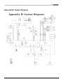
1FF!(5#\&R]&$%$-!0&5#17+10 666666666666666666666666666666666666666666666666666666666666666666666666666 XS
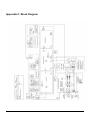
1FF!(5#\&2]&R")2^&5#17+10 66666666666666666666666666666666666666666666666666666666666666666666666666666 XJ
1FF!(5#\&5]&F2R&"1%)'-$ 666666666666666666666666666666666666666666666666666666666666666666666666666666666 XU
1FF!(5#\&!]&#(-!+(1"&F"'0R#(7 666666666666666666666666666666666666666666666666666666666666666666666 3N3
1FF!(5#\&.&_&$2/!01-#2$66666666666666666666666666666666666666666666666666666666666666666666666666666666 3NH
34	@:AEG>@*A9
343&!"#$%$&'()&&7898:;<&58=>:*?@*A9
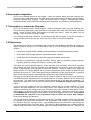
ELISYS UNO is a computer controlled instrument system, capable of automating any or all stages
of assay processing that involve these functions:
fluid handling ......... aspirating and dispensing from 2 uL to 2.5 mL
incubating.............. heating to 25°C or 37°C: probe/coil to 37°C or ambient, and
reaction plate to 25°C, 37°C, or ambient.
Mixing.................... reaction plate only
strip washing ......... 8-wells simultaneously
timing..................... from 1 sec to 24 hours
optical reading....... UV/Visible range
calculating ............. using numerous preprogrammed equations
data storage .......... unlimited capacity
reporting ................ with many options and customization to choose from.
The system allows you to define and program an unlimited number of customized protocols by
selecting displayed menu options from a Microsoft Windows‚1 software program. This open system
can be programmed to perform any of the colorimetric biochemistry assays or EIA assays that can
be handled using the volumes, temperatures, and wavelengths provided. It has many possible
applications in clinical and veterinarian testing, environmental testing, food and water analysis, life
science research, and may also be used in production processes involving micro volume
dispensing, diluting, incubating, reading, washing, and so on.
Service Manual ELISYS UNO
1/106
34B&C;:9*9D=&;9E&F:8>;G@*A9=
!
For in-vitro diagnostics use.
C1+(#(7
34B43	@89E8E&'=8
The ELISYS UNO is designed for use in processing general chemistry and enzyme-linked
immunosorbent assays (“ELISA” or “EIA”), including clinical diagnostic assays, requiring multi-step
washing, rinsing, and soaking. This general purpose instrument is intended to be used by laboratory
professionals who are capable of selecting the appropriate features and options for each specific
clinical application.
!
Some diagnostic assays utilize materials which are potentially biohazardous.
!
Always wear protective apparel and eye protection while using this instrument.
!
Always operate the instrument with the aerosol shield lowered.
!
Do not use the instrument in a manner not specified by the manual, or the protection
provided by the instrument may be impaired.
!
Probe tips are sharp and may cause bodily injury. Do not place hands or fingers under the
probe or wash head probes while instrument is in operation. Always set the power switch to
OFF (0) before working on the probe or wash head. Never touch the probe or wash head
while the instrument is operating.
!
C1+(#(7
The probe performs a self-clean periodically while the probe
is idle. Keep hands away from the probe at all times when
the instrument is ON (1).
!
If the waste bottle is overturned during operation, immediately set the power switch to OFF
(0). If the hydrophobic filter becomes wet due to an overturned waste bottle, it will be
blocked. Continued use of a blocked filter will impair washer effectiveness and/or result in
damage to the instrument.
!
The wash and rinse bottles are pressurized during normal operation. Do not remove bottle
caps or tubing connections while the bottles are pressurized. Turn off the instrument before
changing bottles, adding more solution, or tubing connections.
!
Solvents such as acetone or thinner will damage the instrument. Do not use solvents to
clean the unit. Avoid abrasive cleaners; the aerosol shield is liquid-resistant, but is easily
scratched.
The exterior of the instrument may be cleaned with a soft cloth using plain water. If needed, a mild
all-purpose or non-abrasive cleaner may be used. A 10% solution of chlorine bleach (chlorine
bleach= 5.25% Sodium Hypochlorite) or 70% isopropyl alcohol may be safely used as a
disinfectant. Take special care not to spill liquid inside the instrument.
Particulate matter in wash solutions can clog washer probe head easily. See the section on cleaning
the probe head for special instructions on removing particulate matter from clogged washer heads.
Please take time to read this manual carefully before using the instrument. For best results,
familiarize yourself with the instrument and its capabilities before attempting any clinical diagnostic
tests. Refer any questions to your instrument dealer.
2/106
Service Manual ELISYS UNO
Retain the original packing material for future use in the event that the instrument is placed in
storage, shipped to another location, or returned for service. Two people or more should lift the
instrument by placing hands under the side panels and lifting.
ELISYS UNO should be installed on a sturdy, level, surface capable of supporting the instrument’s
weight (45 kg) safely. The instrument should be surrounded by the following clearances: 46cm on
each side, 117cm on top, 15cm front, and 18cm back. ELISYS UNO requires no fastening to the
bench top.
#0F)+-1(-&)F!+1-#(7&F+!21'-#)($`
The quality of washing often affects the validity of test results. To assure adequate washing:
!
Perform periodic dispense volume repeatability checks as described in this manual.
!
Rinse the wash head and probe after use.
!
Handle and store the wash head carefully to prevent damage.
!
Use the prime cycle before each wash.
!
Watch the instrument to see that the probe and wash head dispense is functioning properly.
Be sure to run a sufficient number of controls in each assay. If controls are not within their
acceptable limits, or if you suspect incomplete or non-uniform washing, disregard test results.
Do not operate the instrument if the pressure is unstable or if the probe or wash head probes are
damaged.
Service Manual ELISYS UNO
3/106
34B4B&7898:;<&$;M8@I&$GOO;:I
Review the following safety precautions to avoid injury and prevent damage to this instrument or
any products connected to it. To avoid potential hazards, use this instrument only as specified.
!
C1+(#(7
Only qualified personnel should perform service procedures.
Contact your dealer to arrange factory training.
34B4H&-A&1ZA*E&.*:8&A:&F8:=A9;<	aG:I
!
Use Proper Power Cord. Use only the power cord specified for this product and certified for the
country of use.
!
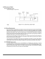
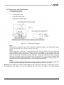
Ground the Product. This product is grounded through the grounding conductor of the power
cord. To avoid electric shock, the grounding conductor must be connected to earth ground. An
optional method is to attach a ground strap from the external grounding terminal on the rear
panel of the instrument to a suitable ground such as to a grounded pipe or some metal surface
to earth ground. See Figure 1.3.4.
!
Observe All Terminal Ratings. To avoid fire or shock hazard, observe all ratings and markings
on the instrument. Consult this manual for further ratings information before making
connections to the instrument.
!
Do Not Operate Without Covers. Do not operate this instrument with covers and panels
removed.
!
Use Proper Fuse. Use only the fuse type and rating specified for this instrument.
!
Avoid Exposed Circuitry. Do not touch exposed connections and components when power is
present.
!
Do Not Operate With Suspected Failures. If you suspect there is damage to this instrument,
have it inspected by a qualified service person.
!
Provide Proper Ventilation. Refer to the installation instructions for details on installing the
product so it has proper ventilation.
!
Do Not Operate in Wet/Damp Conditions.
!
Do Not Operate In An Explosive Atmosphere.
!
Keep Instrument Surfaces Clean and Dry.
!
C1+(#(7
4/106
The operation of ELISYS UNO may involve the use of biohazardous material.
Refer to your owner’s manual for biohazard warnings.
Service Manual ELISYS UNO
34B4K&$;M8@I&-8:O=&;9E&$IOYA<=
The following terms appear in this manual:
51(7!+&indicates an injury immediately accessible as you read the marking.
C1+(#(7&indicates an injury hazard not immediately accessible as you read the marking.
21'-#)(&indicates a hazard to property including the product.
R#)/1b1+5&indicates biological agents that can cause disease in humans. Lab workers handling
potentially infectious materials must use universal precautions to reduce the risk of exposure to
these agents.
These symbols may appear on the product:
!
C1+(#(7
Risk of Shock
F:A@8>@*Z8&7:AG9E
(Earth) Terminal
21'-#)(
Refer To Manual
R#)/1b1+5
Risk of Infection
.'$!] For continued protection against risk of fire, replace only
with fuse of the specified type and current ratings. Disconnect
equipment from supply before replacing fuse.
!"#$%&
51(7!+]&Pinch points, sharp points, and moving parts mechanisms may operate without warning.
!
!
Service Manual ELISYS UNO
5/106
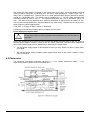
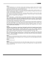
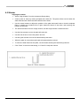
34H&";IAG@
Refer to the figures on the following pages for illustrations of the ELISYS UNO and its components.
!
C1+(#(7
!
C1+(#(7
Hazardous line voltages are present behind the AC cover and on the
power supplies. Always disconnect the external AC power cable before
servicing the instrument.
The operation of ELISYS UNO may involve the use of biohazardous
material. Refer to the Owner’s Manual for biohazard warnings.
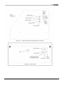
ELISYS UNO Component
Figure Number
ELISYS UNO Exterior View A
Figure 1.3.1
NOTE: For clarity of illustration, the aerosol
shield is not shown.
ELISYS UNO Exterior View B
Figure 1.3.2
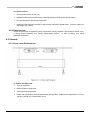
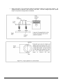
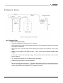
Right Side Panel
Figure 1.3.3
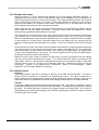
Rear Panel layout
Figure 1.3.4
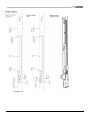
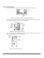
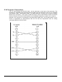
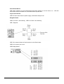
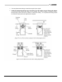
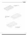
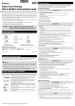
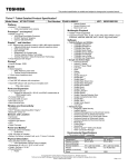
Sub-assemblies:
Plate X Mover
Figure 1.3.5
Plate Y Mover
Figure 1.3.6
NOTE: Plate X and Y Movers are
combined and are responsible for the plate
carrier movement.
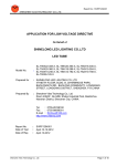
Rack Y Mover
Figure 1.3.7
NOTE: Responsible for the sample and
reagent rack’s movement
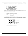
Probe X Mover
Figure 1.3.8
Probe Z Mover
Figure 1.3.9
NOTE: Probe X and Z Movers are
combined and are responsible for the
probe movement.
6/106
Service Manual ELISYS UNO
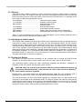
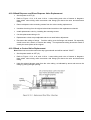
ELISYS UNO Component (Continued)
Figure Number
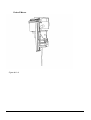
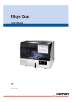
Washer
Figure 1.3.10
NOTE: Responsible for the aspiration and
dispensing of liquids using the wash head.
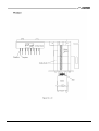
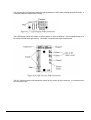
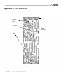
Electronics Rack
Figure 1.3.11
NOTE: Holds the main boards (PCAs) and
the power circuitry.
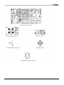
Pressure and Valve Bracket
Figure 1.3.12
NOTE: Controls the fluid flow of the
washer.
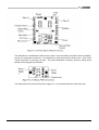
Syringe Pump
Figure 1.3.13
NOTE: Controls the fluid flow of the probe.
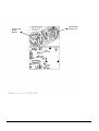
Photometer
Figure 1.3.14
NOTE: Houses the lamps, filters, and is
responsible for photometric readings.
Bottles
NOTE: Holds
system.
Figure 1.3.15
liquids
for
the washer
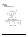
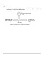
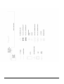
ELISYS UNO Coordinate System
Figure 1.3.16
NOTE: Explains the coordinate system for
ELISYS UNO
Service Manual ELISYS UNO
7/106
8/106
Service Manual ELISYS UNO
Service Manual ELISYS UNO
9/106
10/106
Service Manual ELISYS UNO
Service Manual ELISYS UNO
11/106
12/106
Service Manual ELISYS UNO
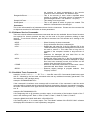
Serial #s 29001782
Serial #s 29001783 to current
!"#$%&'()*+*,
Service Manual ELISYS UNO
13/106
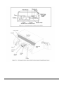
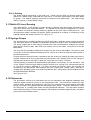
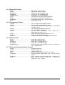
F:AY8&b&0AZ8:
!"#$%&'()*+*-
14/106
Service Manual ELISYS UNO
Service Manual ELISYS UNO
15/106
16/106
Service Manual ELISYS UNO
Service Manual ELISYS UNO
17/106
18/106
Service Manual ELISYS UNO
Service Manual ELISYS UNO
19/106
34K&-8>L9*>;<&$?8>*M*>;@*A9=
-8>L9*>;<&$?8>*M*>;@*A9=&MA:&!"#$%$&'()
!"#$%&&
Dimensions
86cm W x 51cm L x 40cm H, approx. weight = 45kg
'#%(#)*+%),+-%./&#+012/#)21)(
Capabilities
dilutions, predilutions, dispensing single or multiple reagents
Pumps
two syringe pumps, sized: 50 uL and 2.5 mL
Probe
316 stainless for maximum reagent compatibility, level sensing
Minimum
and
maximum 2 uL - 1.95 mL
volume
Precision
<1%
Maximum
number
of 96
specimens
(including
calibrators and controls)
Maximum number of reagents 40 (assorted replaceable racks and custom designed racks
are available for various bottle sizes.)
Reaction vessel
standard microwells, strips or plates
Instrument bottles
! 2L wash with low volume warning sensor
! 1L rinse (or 2nd Wash) with low volume warning sensor
! 2L waste with full warning sensor
! 1L priming bottle
3)456%*1)(7+81.1)(+%),+8#./#$%*5$#+9:)*$:&
For EIA’s
incubation of each row of 8 is timed separately
Thermal control
plate/well 25°C, 37°C, or remains at ambient. (Temperature
controlled to 25°C providing the ambient room temperature is
below 25°C). The reagent and sample racks are not
temperature controlled.
;%2<1)(
Wash head
8-probe, automatic prime and rinse
Programs
create and run user programmable protocols (aspirate,
dispense, soak); can wash wells for re-use as applicable
'#%,1)(
Optical design
reads absorbance in 4 simultaneous channels, NIST traceable
calibration, user selects monochromatic or bichromatic results
Light source
tungsten halogen lamp
8-position filter wheel
340, 405, 450, 505, 545, 600, 630, 700 or custom
Interference filters
long life, hard coat, ion assisted deposition, +/- 2nm, 10nm
typical half bandpass
Linear range
-0.2 to 3.0A
Photometric accuracy
! ± (1% of the reading +0.005A from 0 to 1.5A)
!
-:=*>%$#
Format
Operating systems
Minimum
system
requirements
Recommended system
Main menu options
20/106
± (2% of the reading +0.005A from 1.5 to 3.0A)
One (1) compact disk
Windows®95/98 or Windows® NT 4.0
Pentium®/133 MHz, 32 MB RAM, 20 MB free HD, VGA
monitor, serial port, Windows® 95/98 or Windows® NT 4.0
Pentium®/333 MHz, 32 MB RAM, 20 MB free HD, SVGA
graphics and monitor, serial port, CD drive, Windows® 95/98,
Windows® NT 4.0
Patients, New Job, Job, Setup
Service Manual ELISYS UNO
-8>L9*>;<&$?8>*M*>;@*A9=&MA:&!"#$%$&'()
Secondary menu options
create/edit protocols, import/export assays, data, etc., Control,
Run, Setup
Calculation modes
absorbance, single standard, factor, fixed time kinetics,
kinetics by standard or factor, multi-calibrator point-to-point,
linear regressions, log-logit, cutoff by absorbance or standard,
and more
Self monitoring modes
lamp, bottle volumes, filters, pressure, vacuum, mechanical
function, and more
QC options
store control data, print Levey-Jennings or QC range plots,
calculate SDs
Serial port
RS232 output only, 9600 Baud, 1 start bit, 8 data, 1 stop, no
parity, no handshake, serial cable provided
?:>#$
Voltage range
100-250VAC
Frequency range
50-60Hz
Power maximum
160W
Installation category
CAT II
@)"1$:).#)*%&+9:),1*1:)2+=:$+-%=#+!/#$%*1:)
! Indoor use
!
Altitude up to 2000 m
!
Temperature 5°C to 40°C
!
Humidity 80% for temperatures up to 31°C decreasing linearly to 50% humidity at 40°C.
!
Mains supply voltage fluctuations not to exceed ±10% of the nominal voltage
'#4:..#),#,+@)"1$:).#)*%&+9:),1*1:)2
Recommended
operating 18-35°C
temperature
Recommended
operating less than 85%
humidity
9#$*1=14%*1:)2
! NRTL listed
!
CE marked
Design and instrument specifications are subject to change without notice.
Service Manual ELISYS UNO
21/106
B4&F:*9>*?<8=&AM&)?8:;@*A9
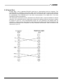
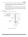
B43&$I=@8O&2A9@:A<&P&!<8>@:A9*>=&+;>Q
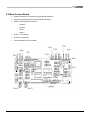
ELISYS UNO has three large printed circuit boards which regulate and control the system. All three
boards are mounted to the top of the electronics rack, easily accessed by lifting the top cover of the
instrument. On the underside of the electronics rack (visible only after the back cover of the
instrument has been removed) are the two switching power supplies and associated junction
boards. See Figures #1.3.11 Electronics Rack, 2.2 Main PCB Connections, 2.3 Coprocessor PCB
Connections, 2.4 Daughter PCB Connections, 2.5.8 DC Junction PCB Connections, and 2.7 Back of
Electronics Rack.
The board on the far left as you face the front of the instrument is “Main” (2900-100). This board
contains one of the two Z180 microprocessors. The other microprocessor can be found on the
“Coprocessor” (2900-200) board, which is the middle of the three boards. The Coprocessor board
has a direct bus interface to the board on the right, known as the “Daughter” (2900-300).
The functions and communications between these boards are described in the next sections on the
following pages.
22/106
Service Manual ELISYS UNO
B4B&0;*9&2A9@:A<&RA;:E
!
External interface to computer (RS-232 Serial Interface)
!
Interface to Syringe Pumps (RS-232 Serial Interface)
!
Position Detection and control of:
!
Probe Z
!
Probe X
!
Rack 1
!
Rack 2
!
Probe / Coil Heating
!
Probe Level Sensing
!
CSI/O Interface to Co-processor
Service Manual ELISYS UNO
23/106
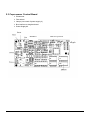
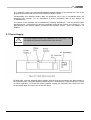
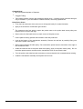
B4H&2A?:A>8==A:&2A9@:A<&RA;:E
" Photometer
" Filter wheel
" Lamps (via control of power supply 2)
" Bus interface to daughter board
" Power Supply #2
54)()6.(.,
"#$%&'()'")*+,)-.//),
01234(.,
24/106
Service Manual ELISYS UNO
B4K&5;GDL@8:&2A9@:A<&RA;:E
" Position Detection and control of:
!
Wash head
!
Plate X
!
Plate Y
" Plate Mixer
" Plate Heater, Temperature Sensor, External Temperature Sensor
" Pressure / Vacuum control
!
Pump
!
Pressure and Vacuum Sensors
" Valves
#
Rinse
#
Wash
#
Bleed
#
Pressure Ctrl
" Bottle Liquid Level Sensors
Service Manual ELISYS UNO
25/106
B4S&1<<&TG9>@*A9&RA;:E=
This section describes these additional boards, their dedicated roles, and their locations.
The Probe Sensor and Heater Control PCB control the fluid sensing and heat control for the coil
block and probe. This board mounts to the top of the coil block.
The probe X board controls the sideways movement of the probe. This board is mounted on the left
side of the probe X bracket under the electronics rack.
26/106
Service Manual ELISYS UNO
The Probe Z board controls the up-down motion of the probe. This board interfaces with the Probe
Sense and Heater Control board located inside the probe housing.
The Rack Y Mover coordinates the motion of Rack 1 (reagent rack) and Rack 2 (sample rack). It is
located on the rear of the Rack Mover Assembly.
The Photometer Junction board is the junction point for the Photometer mechanism. The board is
located on the Photometer Module.
Service Manual ELISYS UNO
27/106
The Photometer PCB optically reads the light emitted by the lamp after passing through the plate. It
is located inside the Photometer housing.
The LED Display shows the status of various states of the mechanisms. See troubleshooting for a
full outline of what each light means. The board is located behind the Probe Shield.
The DC Junction board is the distribution center for DC power for the instrument. It is located under
the electronics rack.
28/106
Service Manual ELISYS UNO
The Plate Mover coordinates the Plate X-axis, Plate Y axis movements, the Plate Carrier incubation,
mixing, fan, and wash movements. It is located to the right and under the Plate Cover. Note: Plate
Carrier connection is currently not used. The extra two-position connector with two orange wires
should not be plugged into the board.
The Relay board turns the second power supply off. It is mounted inside the electronics rack.
Service Manual ELISYS UNO
29/106
B4J&0;*9&;9E&2A?:A>8==A:
The cable from J8 of the Main board (2900-100) to J12 of the Coprocessor board (2900-200)
interconnects the two processors and allows them to communicate. This connection uses a version
of the Z180’s CSI/O (Clocked Serial I/O). When a command is received from the PC by Main, the
firmware on the Main board will determine if the command must be executed by the Coprocessor.
This is the case, for example, when sending a command such as !WPRI, Wash Prime. Since both
the wash head and the pressure system are controlled by the Coprocessor, it is responsible for
executing this command. Using the CSI/O connection, Main will forward this command to the
Coprocessor and wait for it to be completed. When the command is complete, the message will be
sent from the Coprocessor to the Main board via the CSI/O connection and then echoed by Main
back to the PC using the serial port.
In addition to the commands originating from the PC, Main and Coprocessor communicate to
coordinate a variety of functions. This communication is transparent and the ELISYS UNO can be
treated as a unified instrument. The only time when it may become necessary for the service
technician to examine the CSI/O connection is if the processors are unable to communicate at
startup. How to diagnose and solve this problem is covered in the troubleshooting section.
The Coprocessor board and the Daughter board should be considered one unit. The Z180
microprocessor on the Coprocessor board directly controls the peripherals on the Daughter board
by means of the bus interconnect. The 26-pin right-angle connectors directly tie together the data
and address buses of the two boards.
B4J43&.*:OV;:8&Z8:=G=&$AM@V;:8
The internal software, usually referred to as the firmware, is responsible for the direct control of the
mechanisms and other systems. The firmware is actually divided into two parts; one for each of the
two Z180 processors inside ELISYS UNO . The communication between the processors is
described above. The firmware is programmed into two EPROMs (UV-Erasable Programmable
Read Only Memory) and installed on the two microprocessor boards. The firmware “Main” is for the
Main board (2900-100) and “Cop” for the Coprocessor (2900-200). The firmware revision will be
printed on the EPROM labels.
30/106
Service Manual ELISYS UNO
The “software” refers to the Microsoft® Windows program running on the external PC. This is the
program that interacts with the user and controls the ELISYS UNO .
Fundamentally this software breaks down all operations into a set of commands which the
instrument can execute. For an explanation of these commands refer to the Section on
Troubleshooting.
The version of the software can be identified by selecting “Help/About...” from the ELISYS UNO
pull-down menu. In this dialog you will see a message in the format “Version x.xx / Build yyy”. The
Build Number is the primary means of identifying the software version. Also, see section 3.1.3
Reports.
B4U&FAV8:&$G??<I
!
The power supplies contain high voltage and can cause injury.
not operate the instrument with the back cover removed
Do
C1+(#(7
See also: System Overview Diagram in Appendix B
ELISYS UNO uses two switching power supplies, both of which are mounted in the lower portion of
the electronics rack. The power supplies should require no maintenance or adjustment in the course
of normal operation. To access the power supplies, unplug the instrument and remove the four
screws which attach the back cover of the instrument.
Service Manual ELISYS UNO
31/106
Facing the back of the instrument, you will see a small box at the right side containing the power
receptacle and the main power switch. (Note that ELISYS UNO has no voltage select switch as the
power supplies are auto switching.) Inside this box are the main fuses for the instrument. See “Fuse
Replacement” for more information. Two sets of AC lines originate from inside this box. One set
goes directly to the first power supply and the other goes to the relay board. The first power supply
converts AC power to provide DC +12V, +5V, and +24V to the instrument. It is always operating
when the instrument is turned on.
The DC output from the first power supply connects to the adjacent DC Junction Board using a 13wire header. This board distributes the DC voltage and has connections for the Main, Coprocessor,
Daughter boards as well as the syringe pumps and internal lamps. See Appendices for the layout.
Only one of J56 or J54 will be connected to the pumps and J10 (+24VDC) powers the internal
lamps. The three connectors J50, J51, and J52 provide +12VDC, +5VDC, and two grounds to each
of the three main boards. The +5V supply should be between +4.9V and +5.25V and the +12V
supply between +11.5V and +12.25V depending on the current load.
The second power supply is turned on and off via the relay junction board, which controls the AC
input power using a 12VDC relay. The relay is controlled by a ULN2003A (U9C) driver on the
Coprocessor board. This second supply provides the lamp and photometer operating voltage. The
lamps are wired directly to this supply to minimize voltage variation. Lamp supply voltage is
approximately +6VDC. This supply also produces +/- 14-15VDC which is routed to the Coprocessor
board at J6. Components VR2, VR3, C37, and C39 regulate these voltages to +/- 12VDC which are
used to operate the photometer circuits. See “Principles of Operation of the Photometer” for more
information.
B4W&C;@>LEAD&2*:>G*@
All valves, motors and pumps are powered through the major boards. The Main board provides +12
volts through an IRF9530A MOSFET Q1A, which is in turn driven by the re-triggerable one-shot
comprised of C14, R5, and U12A. The microprocessor re-triggers U16A at intervals smaller than
the one-shot period. If the microprocessor system “crashes” or otherwise malfunctions, U12A will
time out and shut down the motors (rack and probe) and coil heating power by turning off Q1A. If
this occurs, LED D3 will be turned off to provide a visual indication.
The Daughter board provides +12V to its systems through a Relay LR2, which is in turn driven by
the re-triggerable one-shot comprised of C27, R17, and U13A. The microprocessor re-triggers
U13A at intervals smaller than the one-shot period. If the microprocessor system “crashes” or
otherwise malfunctions, U13A will time out and shut down the valves and pumps by turning off
Relay LR2. If this occurs, the middle bar of a seven segment LED on the Daughter board will be
turned off to provide a visual indication on the Daughter board.
32/106
Service Manual ELISYS UNO
B4X&0A@*A9&2A9@:A<
Refer also to section 3.5 Motor Control for general information on motion sensing.
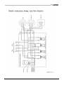
+;>Q=
Two bidirectional DC motors, under microprocessor control, turn 3/8-16 machined stainless steel
lead screws via neoprene belts and nylon pulleys. One motor is dedicated to Y motion of the rack 1
(reagent), the other to the Y motion of the rack 2 (sample). Attached to the lead screw is an
encoder wheel which has ten holes that create pulses when passing between an IR LED and a
phototransistor creating tachometer pulses provided to microprocessor. These tachometer pulses
are provided to the microprocessor at the CLK1 input and CLK2 input at 8254 U5.
Micro switches positioned at extremes of rack movements disable the motor drivers U22 via NAND
gates U18 when the travel limits are reached. Two switches additionally indicate the home positions
to the microprocessor. LEDs D1 and D2 provide visual feedback to the service technician of the
tach pulses and home positions. The Rack Junction PCB holds the motor drivers. The index pulse
buffers, and limit logic, are on the Main PCB. The rack junction connects to Main via 10 pin ribbon
cable and two wire power cable.
F<;@8
Two bidirectional DC motors, under microprocessor control, turn 3/8-16 machined stainless steel
lead screws via a 55 tooth 40 DP timing belt and two 27 tooth 40 DP timing pulleys. One motor is
dedicated to X motion of the plate carrier, the other to the Y motion of the plate carrier. Each drive
pulley attached to the motor has an encoder wheel with ten holes which create pulses when passing
between an IR LED and a phototransistor, providing tachometer pulses to the microprocessor at the
CLK1 input and CLK2 input at 8254 U16. Phototransistors, positioned at extremes of the plate
carrier movements, disable the motor drivers U7 and U11 via NAND gates U10 and U18 when the
travel limits are reached. Two of these phototransistors additionally indicate the home positions to
the microprocessor. LED D1 on the Daughter board provides visual feedback to the service
technician of the tach pulses and home positions. The plate mover junction PCB holds the motor
drivers. The Daughter PCB holds the index pulse buffers, limit logic, and connects to the main PCB
via a 26-pin ribbon cable and power. Additionally, phototransistors generate X and Y axis index
pulses to position the plate carrier with regard to the photometer.
0*[8:&c$L;Q8:d
Mixing in wells is accomplished by shaking the Plate Carrier Y-axis platform. The platform is
supported by 4 flexible natural latex rubber mountings and is attached to the underside of the
platform (a motor driven counterweight). Spinning the counterweight causes the platform to shake
on its mountings with proportional intensity. Microprocessor control of the shaker motor via U7 on
the coprocessor PCB allows for adjusting the single mix/shake intensity setting. Adjust the mixing
using Telix command, !MSPDxxxx. Adequate mixing should shake 250uL of reagent and sample
vigorously, but without splashing up. Speeds 0030 to 0050 should cover the range.
Service Manual ELISYS UNO
33/106
F:AY8&\
A bidirectional DC motor, under microprocessor control, pulls a slide via a nylon belt and nylon
pulleys. The motor is dedicated to X motion of the probe. Probe X has a two-phased encoder
wheel which creates pulses when passing between a reader, providing tachometer pulses to the
microprocessor at the NMI input and PB4 input at 8255 U9. The one phase of the index pulley is
used by the software to determine direction and accurately track the probe’s position. The probe-X
junction board contains some jumpers that should not be adjusted.
Another phototransistor,
positioned toward the right side of the probe X movement, is used to verify and if necessary, reset
the probe count additionally.
Another phototransistor indicates the home position to the
microprocessor. LED D1 on the Main board provides visual feedback to the service technician of
the tach pulses and home positions. The Probe X Junction PCB holds the motor driver. The main
PCB holds the limit logic and connects to the Probe X Junction PCB via a 10-pin ribbon cable and
power.
F:AY8&b
A bidirectional DC motor, under microprocessor control, turns a 1/4-20 machined brass lead screw
via neoprene belt and nylon pulley. The motor is dedicated to the vertical Z motion of the probe.
Probe Z uses a shuttle with an attached aluminum code wheel that has index holes which create
pulses when passing between an IR LED and a phototransistor, providing tachometer pulses to the
microprocessor at the CLK0 input at 8254 U5. There is a phototransistor positioned at the extreme
of the probe Z movements. It will disable the motor drivers U27 via NAND gate U18 when the travel
limits are reached.
Additionally other phototransistors indicates the home positions to the microprocessor. LED D2
provide visual feedback to the service technician of the tach pulses and home positions. The Probe
Z Junction PCB holds the motor driver and interfaces to Probe Sense board. The main PCB holds
the index pulse buffers, limit logic, and connects to the Probe Z Junction PCB via a 10-pin ribbon
cable.
C;=L8:
One bidirectional DC motor, under microprocessor control, turns a 3/8-16 machined stainless steel
lead screw via neoprene belt and nylon pulley. The motor is dedicated to vertical Z motion of the
wash head. The pulley has several index holes which create pulses when passing between an IR
LED and a phototransistor, providing tachometer pulses to the microprocessor at the CLK0 input at
8254 U16. Phototransistors, disables the motor driver U11 via NAND gate U10 when the travel
limits are reached. Travel limits are indicated by encoder flag slot attached to the washer shuttle.
The 7-segment LED on the daughter board provides visual feedback to the service technician of the
tach pulses and home positions. The plate mover junction PCB contains the motor drivers and
connects to the daughter board via a 26-pin ribbon cable. The daughter PCB holds the index pulse
buffer, and limit logic.
B43N&F<GOY*9D
B43N43&F:8==G:8&;9E&,;>GGO
Solid-state sensors P1 and P2 on the Daughter board are amplified at U6 and U8 and time division
multiplexed via U9 into V/F converter U14, then measured at 8254 timer U2. This provides
feedback to the microprocessor for coordinating pump activity and displaying measured pressure
and vacuum levels. The vacuum pump is driven by U3 and MOSFET Q2A. The valves are driven
by U3 and U15.
34/106
Service Manual ELISYS UNO
B43N4B&FGO?=&;9E&,;<Z8=
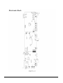
Refer to Figure # 1.3.12 for pictorial and Appendix E for Fluid System Schematic diagram. A
diaphragm pump and valves, under microprocessor control via the daughter PCB, are switched on
and off to generate pressure or vacuum as necessary. Two electromechanical valves, the pressure
control valve and the bleed valve, are used to control and maintain the pressure in the system’s
wash and rinse bottles. The pressure control valve, controlled by U3, is an intermittent duty valve
which regulates the pressure in the wash and rinse bottle.
When energized, the valve closes, causing pump pressure flow to be diverted from ambient into the
check valve and into the bottles and sensor. The bleed valve allows the instrument to relieve
pressure during standby and when power is removed.
The bleed valve is a continuous duty valve, also controlled via U3, and is continuously closed during
any pressure cycle. It also serves as an emergency pressure relief valve in the event of power
failure or microprocessor crash and opens when pressure is no longer required such as in standby
or when timed out. A check valve, oriented to allow flow to the bottle side only, assures that the
pressure is maintained on the bottle side of the system. Pressure is sensed by the circuit of P2 and
U8.
Pressure build up occurs in the wash and rinse bottles simultaneously, producing positive wash and
rinse fluid pressure in the wash and rinse lines of the system (see Appendix E). Two intermittent
duty valves called the Rinse Valve and Wash Valve, which are normally closed, are pulsed open
via U3 on the Daughter Board. The valves are used to regulate the flow of rinse and wash fluid to
the washer head by precisely timed openings.
When the control valve is open to ambient and the pump is running, the pressure will not change
and only vacuum will be produced by the pump. The vacuum side of the pump is connected to the
waste bottle. Vacuum is monitored by microprocessor control by monitoring the output of solid state
pressure sensor circuit P1 and U6 on the Daughter PCB and switching the pump on and off
accordingly. Vacuum is not regulated but is monitored. Refer to “Error Messages”, “Status
Indicators”, and Plumbing- Bottle Level Sensing.
B43N4H&C;=L&$I=@8O
5*=?89=8
The pump produces 34.5 kPa air pressure at the top of the wash and rinse bottles. The fluid is
forced up from the bottle but is stopped by a solenoid pinch valve. The valve is opened for a
precise interval under microprocessor control to allow fluid to flow into the dispense cavity of the
wash head, where it is distributed to stainless steel capillary tubes and then into eight microwells.
1=?*:;@8
A vacuum is applied to the waste bottle any time the pump runs. The pump is connected to a fine
hydrophobic aerosol filter then connected to the waste bottle. The filter prevents liquid from entering
the pump. The waste bottle also connects to the aspirate cavity of the wash head. The vacuum is
distributed across stainless steel capillary tubes thereby aspirating the contents of eight microwells
simultaneously from the plate.
Service Manual ELISYS UNO
35/106
B43N4K&&5:;*9*9D
The probe empties and flushes in the wash cup. Liquid exits the wash cup through tubing that
drains into a waste trough underneath the rack mover. From there liquid drains to the drain bottle
by gravity. The washer aspirates liquid from the plate into the waste bottle. The wash trough
drains, by gravity, into the Waste Trough.
B433&RA@@<8&.*<<&"8Z8<&$89=*9D
The signal BOTLV is fed through a voltage divider to stainless steel wire probes mounted in the
caps of the wash, rinse, and waste bottles. The signals are time division multiplexed via U9 into
V/F converter U14 and the resulting frequency appears at the CLK2 input of 8254 timer U2. The
microprocessor reads a change in frequency which corresponds to a change in conductivity of the
material between the probes. Refer to 1.3.3 and 1.3.15.
B43B&$I:*9D8&FGO?=
The syringe pump is an OEM component of the ELISYS UNO consisting of two syringe drives and
one valve drive which are capable of independent operation through its own microcontroller board.
The pump module has its own internal command set, and communications between the syringe
pump and the ELISYS UNO Main PCB occur serially via a 3 wire cable connected to J2 on the
Main Board.
The valve has four possible positions that connect any two ports at right angles. The valve is used
in only two of the four positions allowing the 2.5mL syringe to connect to either the priming tube or
the interconnect tube.
Priming fluid from the prime bottle is introduced into the system by rotating the shear type valve to
connect between the 2.5mL syringe and the priming tube, then drawing down on the syringe to
aspirate prime fluid from the bottle. A third port, on the top of the valve, is unused.
Volume pipetting is produced by displacements generated in two syringes: 2.5 mL and 50 uL. The
2.5 mL syringe is used for large reagent volumes and the 50 uL syringe is for volumes less than 30
uL. The 50 uL syringe is attached to a “T” fitting, and does not require a valve. The syringes are
connected by an interconnect tube between the valve (2.5mL) and T-fitting (50mL), and this is
coupled to the pipetting system by a feeder line between the T-fitting (50mL) and a coupled line into
the heat block/probe assembly.
See Figure #1.3.13.
B43H&FLA@AO8@8:
The photometer consists of a mechanism with its own electronics and additional calibration and
analog to digital conversion circuitry on the Coprocessor PCB. The mechanism contains the light
sources, filters, detectors and electronics. Light from four tungsten-xenon lamps passes downward
though four wells in the sample plate and the samples they contain. Inside the sealed box, under
the read wells, is a rotating filter wheel and four photodiode detectors. The filter wheel contains
eight interference filters of various wavelengths, and is speed controlled to approximately 3 rotations
per second under software control.
36/106
Service Manual ELISYS UNO
While in motion, as each filter passes in front of the photodetector, an infrared optical switch triggers
a sampling of the peak voltage by the Coprocessor board. The four voltages are then fed to four
comparators which each compare the sampled voltage to the output of an exponential capacitor
decay circuit. The pulse at the output of the four comparators enables individual 16 bit counters in
two 8254 programmable timers. The counts are read by the microprocessor and this completes the
analog to digital conversion.
The photo detector output is proportional to the intensity of the light, whereas the width of the
positive phase of the comparator output is proportional to the absorbance. The resistance across
the log cap (RC decay) determines the base of the log (10 for absorbance) and is used to adjust the
low-end absorbance calibration (gain). Another four potentiometers are used to adjust the high-end
absorbance (offset) of each channel.
Service Manual ELISYS UNO
37/106
B43K&2AO?G@8:&2A998>@*A9=
The PC communicates with ELISYS UNO via the serial port on the back of the instrument. The
connector is a standard 9-pin serial port and the cable from the instrument to the PC is a standard
“Null Modem Cable”. (“Null Modem Cable” is a cable made with a female 9 pin connect to another
female 9 pin connector.) In this type of cable the RX/TX (receive and transmit) and the CTS/RTS
lines are crossed. The serial communication is at 19,200bps, 8 data bits, no parity, and 1 stop bit.
Internally, the serial port is connected to the Main board (2900-100). The microprocessor on this
board is responsible for communication with the PC and the Coprocessor and for routing
commands within the ELISYS UNO .
38/106
Service Manual ELISYS UNO
B43S&2AO?G@8:&$AM@V;:8	@8:M;>8
B43S43&![?<;9;@*A9&AM&@8:O=
Each of these terms is explained in more detail in the Owner’s Manual.
Patient Database.... Stores complete patient records including name, address, and doctor
information.
Sample Protocol..... Procedure for aspirating and dispensing reagents or samples.
Wash Protocol ........ Procedure for washing wells.
Method.................... Calculation modes and parameters for an assay.
Assay...................... A test, made up of protocols, parameters, and options necessary to run a test.
Panel ...................... A group of assays that are frequently run together.
Job Also known as a worklist, it contains the list of patients (or patient IDs) and assays to run.
Service Manual ELISYS UNO
39/106
B43S4B&(;Z*D;@*9D&@L8&=AM@V;:8
When you first start ELISYS UNO you will be asked to log in with a username. At present this is
used only for record keeping as this username will be printed in reports. It is not necessary to enter
a password.
ELISYS UNO uses the standard Windows“ 95/98 Windows NT“ 4.0 controls, windows, and dialogs.
If you are unfamiliar with these controls and how to use them, please refer to your Windows“
documentation. All of the ELISYS UNO functions are available from the pull-down menus at the top
of the program. Some of the more common functions are also available from the main menu.
B43S4H&!"#$%$&'()&&=@;@G=&V*9EAV
This window displays the current status of the instrument including the temperature and the status
of the waste, wash, and rinse bottles. Also shown are the currently loaded racks and plate. The
“Functions” button will start the “Instrument Functions” dialog described in the Owner’s Manual. The
“Wash Wells” will wash all twelve rows of the plate currently loaded in the instrument. Use the “New
Wells” button to tell the software that you have inserted a new plate or set of wells. All wells will be
marked as available. The software automatically keeps track of which wells in the plate have been
used. To manually edit this setup, or to mark certain wells as not available, click the “Edit Plate”
button.
Note: The “Wash Wells” and “New Wells” functions are also available from the “Run” menu.
B43J	=@:GO89@&.G9>@*A9=
This dialog gives you easy access to some of the more common instrument functions. To open it, go
to the “View” menu and select “ELISYS UNO functions”. The following options are available:
Note: The “Start of Day” and “End of Day” functions are also available from the “Run” menu.
Start of day ............. Prepares the instrument to be run by turning on the photometer lamps, washing
the probe, and priming the wash system.
End of day .............. Prepares the instrument to be shut down at the end of the day by turning off the
photometer lamps, washing the probe, and rinsing the wash system.
Reset ...................... Homes all of the mechanisms and reinitializes the syringes.
Standby .................. Parks the probe and turns off the pressure system.
Park probe.............. Moves the probe to the center wash station.
Wash probe............ Washes the probe.
Prime wash............. Primes the wash system with the solution in the wash bottle.
Prime Syringes....... Primes the syringes with fluid from the prime bottle.
Prime rinse ............. Primes the wash system with the solution in the rinse bottle.
Wash Wells ............ Washes all twelve rows of the plate.
Heat to 37°C........... Raises the coil and plate temperature to 37°C.
Temp Off ................ Turns the coil and plate temperature off.
40/106
Service Manual ELISYS UNO
H4&-+)'R"!$/))-#(7
In this section, each subassembly or component group is discussed, and possible problems and
solutions are outlined.
H43&$8:Z*>8&-AA<=
H4343&-8=@&0AE8
When servicing the instrument it is often necessary to be able to send commands directly to the
ELISYS UNO . This can be done by selecting “Telix Mode” from the View menu. This mode displays
the communication with the instrument and allows the commands to be typed in and executed. For
an explanation of the ELISYS UNO commands see Service Tools- Software Service Commands.
&2;G@*A9]&&It is possible to damage the instrument by sending incorrect commands.
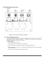
H434B&$@;@G=	E*>;@A:=
0;*9&RA;:E
There are two 7 Segmented LEDs:
Service Manual ELISYS UNO
41/106
F:AY8&$89=8&RA;:E
LED status indicators on the Probe Sense PCB show whether or not the heat is on. LED D11
shows the heat for the heater coil, LED D8 shows the probe heat.
2A?:A>8==A:&RA;:E
LED D10 shows the status of power supply, and should always be on.
5;GDL@8:&RA;:E
LED D12: Plate Y slot indexing. LED D13: Plate X slot indexing.
LED 7 Segment
F<;@8&0AZ8:&TG9>@*A9
LED D14: status indicator of the thermistor on the Plate heater.
LED D15: currently not in use.
LED Display Board:
42/106
Service Manual ELISYS UNO
H434H&+8?A:@=
The ELISYS UNO software includes a number of functions intended to make it easier to diagnose
problems in the field. For example, there are several files and reports which the end-user can send
back to the service center. At the top of every report printed by ELISYS UNO is a message in the
form: ssss/v.vv bbb/xxxx/yyyy/ppp-ddd, where
ssss indicates............................................. Instrument serial number
v.vv indicates ............................................. Software version number
bbb indicates.............................................. Software build number
*
See note below
xxxx indicates............................................. Main firmware revision
yyyy indicates............................................. Coprocessor firmware revision
ppp indicates.............................................. Primary filter (if the report is for a single assay)
ddd indicates .............................................. Differential filter (if the report is for a single assay)
*Note: If a set of parenthesis with another v.vv and bbb appear, you are viewing a data file with a
different version than the data file was created under.
H434K&'?E;@*9D&@L8&E8M;G<@&:8?A:@=
The ELISYS UNO software includes a set of default report templates including a template for each
mode and for various special reports. The user can edit these default reports, but the software
contains a way to restore them to their original form at any time. This may become necessary if the
user-edited report templates contain errors which prevent them from being used. From the Setup
menu of the software, select Preferences and then Default Reports. The Default Reports Setup
dialog will be shown. Select the button “Restore/Update all default report templates” to restore all of
the standard templates. It is recommended that custom reports be created by first copying one of
the default reports to a new name. For more information on report templates please see the Report
Template Specification in the Owner’s Manual.
H434S&$I=@8O	MA&+8?A:@
The system info report provides information on the computer that is running the ELISYS UNO
software. To access this report, select “System Info” from the “Help” menu of ELISYS UNO .
The Windows® version section will report information regarding the Windows‚ installation. In
Windows‚ 95 the “SP” section will report the system revision.
21'-#)(]&-L8:8&;:8&=8Z8:;<&Q9AV9&?:AY<8O=&V*@L&@L8&Z8:=*A9=&AM&C*9EAV=e&XS&?:*A:&@A
fRg&VL*>L&EA&;MM8>@&!"#$%$&'()&4&#M&@L8&G=8:&L;=&A98&AM&@L8&8;:<*8:&Z8:=*A9=&AM&C*9EAV=e
XS&@L8&=I=@8O&=LAG<E&Y8&G?D:;E8E4
ELISYS UNO has been tested with Microsoft® Windows 95B, 95C, 98, Windows NT® 4
Workstation, Windows NT® 4 Server, and Microsoft® Windows® 2000 Professional, Beta 3.
The Processor section will show information regarding the computer itself. The MHz speed of the
computer is not available under Windows® 95/98. The Memory section will report the total amount
of physical and virtual memory. There should be at least 8MB (8096K) of physical memory. The total
virtual (Page) memory should be at least twice the physical memory. If it is not, the user should
change the virtual memory settings under the Windows® Control Panel.
Service Manual ELISYS UNO
43/106
H434J&'=*9D&!"#$%$&'()&&F;>Q
ELISYS UNO Pack (CWPack) is a supplemental stand-alone program designed to ease the
transfer of various ELISYS UNO data files (assays, jobs, racks, data, etc.). Because the
functionality of ELISYS UNO Pack will eventually be integrated into the main ELISYS UNO
program, CWPack has been kept intentionally simple and inflexible. Contact your dealer if you do
not have CWPack on your computer. There are two basic operations that CWPack can perform,
packing and unpacking.
F;>Q*9D&M*<8=
! To pack a group of files, perform the following steps:
!
Using the “File Management” functions within ELISYS UNO , export all files to be transferred to
an empty directory.
!
Start CWPack by selecting on the Windows‚ Start Menu -> Programs -> ELISYS UNO ->
ELISYS UNO Pack. There is a checkbox option: “Unpack files”, and two directory/file name
entry boxes: “ELISYS UNO Export Directory” and “Package File Name.”
!
Make sure the “Unpack files” option is not checked.
!
“ELISYS UNO Export Directory” always defaults to “a:\ELISYS UNO ”. If you exported your
files to a different directory, enter the name of that directory here.
!
“Package File Name” always defaults to “a:\ELISYS UNO \CWPack.pck”. If you would like the
pack file to go into a different directory, or have a different name, enter that information here.
!
Press the button labeled “Start”.
!
CWPack will now process the ELISYS UNO export files into a pack file. When it is done, the
status window will report “Pack Successful!”.
!
You may now transfer and/or email the .PCK file to it destination.
'9?;>Q*9D&M*<8=
To unpack a packed file, perform the following steps.
!
Start CWPack by selecting on the Windows‚ Start Menu -> Programs -> ELISYS UNO ->
ELISYS UNO Pack. There is a checkbox option: “Unpack files”, and two directory/file name
entry boxes: “ELISYS UNO Export Directory” and “Package File Name”
!
Make sure the “Unpack files” option is checked.
!
“ELISYS UNO Export Directory” always defaults to “a:\ELISYS UNO ”. Enter the name of a
new or empty directory here. Do not enter the name of your ELISYS UNO data directory here.
!
“Package File Name” always defaults to “ a:\ELISYS UNO \CWPack.pck “. Enter the name of
the file to be unpacked here.
!
Press the button labeled “Start”.
!
CWPack will now process the packed file and put the files into the directory you specified.
When it is done, the status window will report “Unpack Successful!”.
!
You may use the “File Management” functions within ELISYS UNO to import the data files.
Additionally, once CWPack has been run at least once, you can double-click on a .PCK file from
within Windows‚ Explorer, and CWPack will start automatically with the “Unpack files” option already
44/106
Service Manual ELISYS UNO
checked, and the name of the .PCK file already in the “Package File Name” entry. In the “ELISYS
UNO Export Directory” box, enter the directory name of your choice.
H434U	=@:GO89@&+8?A:@
With the computer connected to the instrument and the instrument turned on, select “Instrument
Setup” from the “Setup” menu of ELISYS UNO . Once the software has gathered the necessary
information from the instrument the “Print Report” button will be enabled. This report displays
several vital statistics regarding the instrument and the configuration stored in the computer.
For an explanation of these functions see the following.
2AOOG9*>;@*A9=
ComPort ..................................................... the name of the port ELISYS UNO is using. Usually
COM1 or COM2.
ComSpeed ................................................. should always be 19200
Handshaking .............................................. should always be 1
$8@@*9D=
AirPlug........................................................ This is the size of the air gap, in microtiters, that is
aspirated following a pickup. 1µL is the default and
should always be sufficient.
DispenseHigh............................................. The is a height, in counts, relative to the bottom of the
well. This specifies that position at which the instrument
will dispense when "Dispense High" is specified in the
sample protocol. The default is 42.
DispenseLow ............................................. The is a height, in counts, relative to the bottom of the
well. This specifies that position at which the instrument
will dispense when "Dispense Low" is specified in the
sample protocol. The default is 35.
LevelDetectOffset ...................................... The level detect offset is used by the software to
account for the difference between the detected liquid
level and the actual liquid level. The default is 0 and
should not be changed.
MinSampleDispense .................................. This is the minimum amount that will be dispensed,
including push volume. The default is 5µL.
MixExtraTime ............................................. This setting is no longer used.
MixSpeed ................................................... This setting is no longer used.
PrbZAspirateFactor.................................... When aspirating from a bottle or vial, the software
calculates the ideal distance to move into the vial to
aspirate the specified volume. This factor is applied to
calculation to account to variation in vial sizes and wall
thickness. The default is 1.35 (35%).
PrbZMinimumDip ....................................... This is the minimum amount, in counts, that the software
will move the probe into the liquid when aspirating. The
default is 6.
PushVolume............................................... This is the default Push Volume used when creating a
new assay. See the sections on assay programming in
the owner's manual for more information. The default is
25µL.
ReagentCutoff............................................ Sample protocols dealing with volumes less than or
equal to this cutoff are treated as "samples". If the
volume is greater or there is a dispense to ALL the
protocol is treated as a "reagent". This distinction
controls which aspirate/dispense method is used. See
Service Manual ELISYS UNO
45/106
the sections on assay programming in the owner's
manual for more information. The default is 20µL.
ReagentVolFactor ...................................... This is the amount of extra volume aspirated when
picking up reagent. This extra volume is necessary to
prevent reagent dilution. The default is 1.20 (20%).
SampleVolFactor ....................................... This setting is no longer used.
SetAirSpeed ............................................... This is the speed at which air gaps are created. The
default is 2 and should not be changed.
F;:;O8@8:=
This is the unformatted list of parameters direct from the instrument. Please see the command list
an alignment sections for information on these parameters.
H434W&$AM@V;:8&$8:Z*>8&2AOO;9E=
There are several software maintenance commands that are also available. None of these functions
are required for normal operation but they can be used to fix some problems relating to data
integrity. To use these functions, type the above command into Telix window as if sending to the
instrument.
~HELP........................................................ Show Summary of these commands.
~JPRG ....................................................... Purge all the data files from a selected job.
~JIDX ......................................................... Rebuild the Job Index file. If the file JobIndex.IDX in the
\JOBS subdirectory becomes damaged this function can
be used to restore it. This make take a long time to
complete if the computer contains a large amount of
data.
~JFIX.......................................................... Searches for damaged job and data files on the
computer and prompts to fix them.
~AIDX......................................................... Rebuild the Assay Index file. If the file AsyIndex.IDX in
the \ASSAYS subdirectory becomes damaged or assay
files have been manually moved, this function can be
used to force the index file to be rebuilt.
~ PRMR ..................................................... Resets all instrument parameters to last known values.
Instrument will then restart. Use with caution.
~REGR....................................................... Restores registry settings to program defaults. See
“Registry” section.
H434X&1Z;*<;Y<8&-8=@=&2AOO;9E=
example: %12.0 5.1 37.4 —.- —.- E F F w —.- Next Rd: none<CR> Commands (listed below) start
with a ‘!’ followed by the four letter command code and any additional necessary parameters. The
line ends with a CR (carriage return).
example: !PLTM02000300<CR>
If the command is invalid an error message will be sent back. If the command is valid the entire
command will be echoed and the instrument will begin processing. When the command is complete,
the entire command will once again be sent back but with the first character (formerly a ‘!’) changed
to a ‘#’.
example: #PLTM02000300<CR>
A line beginning with a ‘@’ denotes a position report. It will consist of the location of each of the 7
axes in the following order: Rack 1, Rack 2, Plate X, Plate Y, Wash Z, Probe X, Probe Z
example: @0200 0100 0225 0400 0001 1520 0050<CR>
A line starting with a ‘%’ is a status report. The “Telix Mode” window of the ELISYS UNO software
will display this information in a self-explanatory categories.
46/106
Service Manual ELISYS UNO
Lines beginning with a ‘*’ are error messages. The three numbers following the asterisk will be the
error code, followed by a colon and then the text message. Error numbers greater than 499
originate from the Coprocessor.
example: *001:Invalid number of parameters<CR>
Lines that begin with a ‘-’ are additional information. Returned parameters, settings, or
configuration etc.
example: -SERN :0000<CR>
Coordinates are always given in 100ths of inches, 0100 = 1 inch. The home position is 0000. Note:
Commands from the instrument will have a checksum inserted between the end of the string and
the carriage return. The “Telix Mode” window of the ELISYS UNO software will normally hide the
checksums, but they will be visible if using a different communications program.
H4343N&7898:;<&2AOO;9E=
!1 ................................................................ Repeat the previous command
!INIT ........................................................... Initialize (home) all axes
!HOME ....................................................... Initialize (home) all axes
!SERN ........................................................ Show the serial number,
returns: “-SERN: xxxx”
!POSI.......................................................... Display position of all axes
!STAT ......................................................... Display temperatures, vacuum, pressure, status of
bottles
!REVS ........................................................ Report the software revisions
!PARM........................................................ Display the current parameters
!PARMnapppp............................................ Edit a parameter. n = par.#, a = par. label (xyz,ect.),
pppp = new par. value
H43433&F<;@8&\P%&2A9@:A<
!PLXH......................................................... Move plate X-axis to home
!PLYH......................................................... Move plate Y-axis to home
!PLTH ......................................................... Move both plate X & Y to home
!PLXMxxxx ................................................. Move plate X-axis to coordinate xxxx
!PLYMyyyy ................................................. Move plate Y-axis to coordinate yyyy
!PLTMxxxxyyyy .......................................... Move plate X & Y to coordinates
!YREF......................................................... Reference the plate Y-axis again the indexing sensor
H4343B&0*[*9D
!MXONtttt ................................................... Turn on plate mixer, tttt = time in seconds
!MXOF........................................................ Turn off mixer
!MSPDssss ................................................ Set mix speed duty cycle, ssss = duty (0030 is the
default). A larger number results in a slower mix speed.
H4343H&C;=L&/8;E&2A9@:A<
!WSHH ....................................................... Move wash head to home
!WSHMzzzz ............................................... Move wash head to coordinate zzzz
Service Manual ELISYS UNO
47/106
H4343K&F:AY8&\Pb&2A9@:A<
!PRXH ........................................................ Move probe X-axis to home
!PRZH ........................................................ Move probe Z-axis to home
!PRXMxxxx ................................................ Move probe X to coordinate xxxx
!PRZMzzzz................................................. Move probe Z to coordinate zzzz
!PRBMxxxxzzz ........................................... Move probe X & Z to coordinates.
!PFFR......................................................... Find fluid level on rack (sense liquid level)
!PARK ........................................................ Move probe to waste area of wash cup.
!PSENxxxx ................................................. Set fluid sensitivity, xxxx = sensitivity level
!PCNT ........................................................ Show probe counts
H4343S&-8O?8:;@G:8&2A9@:A<
!COON ....................................................... Turn on probe coil temperature control
!COOF........................................................ Turn off probe coil temperature control
!COILtttt...................................................... Set the coil temperature control point, tttt = temperature.
ex: 0370 = 37°C
!TCON ........................................................ Turn the plate temperature control on
!TOFF......................................................... Turn the plate temp control off
!PLATtttt ................................................. Set the plate temperature control point. tttt =
temperature. ex 0370 = 37°C
!TCHK ........................................................ Check if the plate temperature is 37°C ± 0.1
!PTON ........................................................ Show external temperature probe
!XMPTxxx................................................... Transmit xxx seconds of readings from thermistors.
H4343J&+;>Q&2A9@:A<
!RK1H......................................................... Move rack 1 (left) to home
!RK2H......................................................... Move rack 2 (right) to home
!RK1Myyyy ................................................. Move rack 1 to coordinate yyyy
!RK2Myyyy ................................................. Move rack 2 to coordinate yyyy
!RKSMxxxxyyyy ......................................... Move both racks at the same time. xxxx = coord.for R1,
yyyy = coord. for R2
H4343U&F:8==G:8P,;>GGO&;9E&,;<Z8&2A9@:A<
!PRON........................................................ Pressure system on
!VAON ........................................................ Vacuum system on
!VOFF......................................................... Vacuum system off
!STBY......................................................... Standby. Turns off both pressure and vacuum.
!SPRSxxxx ................................................. Set the pressure control point. xxxx = PSI. ex: 0040 =
4.0psi.
!VCALxxxx ................................................. Set or display volume calibration. xxxx = volume in mL.
!SSEN ........................................................ Show sensor levels. -Wash:xxxx
Waste:xxxx
Rinse:xxxx xxxx = counts
48/106
Service Manual ELISYS UNO
H4343W&5*<G@8:&2A9@:A<
!WPRBvvvv ................................................ Wash probe tip. vvvv = volume in uL, 2000 = 2.0mL, if
vvvv is not specified the default is used.
!PWSH ....................................................... Specifies the default probe flush volume. See !PARM
and !WPRB.
!DINIx ......................................................... Initialize the syringe pumps. x = number of times.
!DPRIn........................................................ Prime the syringe pumps. n = number of times to prime.
!DCALxxxx ................................................. Scale factor for small syringe. ie. 1000 => multiple
specified volume by 1.000.
!DASPvvvvSx............................................. Aspirate into syringe. vvvv = volume in uL (large or small
chosen automatically). x = syringe speed.
!DDSPvvvvSx............................................. Dispense from the syringe. vvvv = volume in uL, x =
syringe speed.
!DMAPvvvvSx ............................................ Make immediate air pocket, vvvv = volume in uL, x =
syringe speed.
!SAIRxxxxSx .............................................. Set air pocket size xxxx = volume, x = syringe speed; air
pocket is added automatically after each wash probe.
H4343X&FLA@AO8@8:
!FLTS ......................................................... Display the available wavelengths.
!CABS ........................................................ Set the absorbance calibration factor.
!SFAC......................................................... Show the absorbance calibration factor.
!LPON ........................................................ Turn the lamps on.
!LOFF ......................................................... Turn the lamps off.
!RFLT ......................................................... Display the filter voltages of the 4 channels at all 8
wavelengths.
!RROWAnnpdnB........................................ Read row (8 wells). nn = strip(1-12), pd = filters, n = # of
readings.
!RWELxnnpdnB ......................................... Read the specified well. x = strip(A-H), nn = strip(1-12),
pd = filters, n = # of readings.
!VWELxnn .................................................. Display the filter volts at well position. x = strip(A-H), nn
= strip(1-12)
!RAIR.......................................................... Take and store an air reading.
!BLNKxnn ................................................... Read and store blank values, x = strip(A-H), nn = strip(112), entered for Channel #2 ((right rear) (all 4 channels,
all 8 wavelengths- refer to error 523.))
!SBLK ......................................................... Displays current stored channel blanks.
Service Manual ELISYS UNO
49/106
H434BN&F:AY8&0;>:A=
!GOWLxnn ................................................. Go to the specified well. x = strip(A-H),nn = strip(1-12).
!GOWDxnnvvvvSs ..................................... Go to the specified well and dispense, x =strip(A-H), nn
=strip(1-12), vvvv = vol. in uL, s = speed(0-9)
!PLVLxxxx .................................................. Probe dispense level at plate height from well bottom to
disp. point
!WELZpppp ................................................ Change Depth of well in relation to probe. pppp = new
depth
!MAXZxxxx................................................. Max probe depth, xxxx = maximum depth over racks.
!GOR1nn .................................................... Go to the specified position in Rack 1, nn = position
number.
!GOR2nn .................................................... Go to the specified position in Rack 2, nn = position
number.
!GR1AnnvvvvSs......................................... Go to the position in Rack 1 and aspirate, nn = position,
vvvv = vol. in uL, s = speed (0-9)
!GR1DnnvvvvSs......................................... Go to the position in Rack 1 and dispense, nn = position,
vvvv = vol. in uL, s = speed (0-9)
!GR2AnnvvvvSs......................................... Go to the position in Rack 2 and aspirate, nn = position,
vvvv = vol. in uL, s = speed (0-9)
!GR2DnnvvvvSs......................................... Go to the position in Rack 2 and dispense, nn = position,
vvvv = vol. in uL, s = speed (0-9)
NOTE: The above commands will be automatically translated by the ELISYS UNO software into
commands of the following form. This allows the software to automatically accommodate the
different racks that can be loaded into the instrument.
!GORKnyyyyxxxx ....................................... Move probe to rack. n = rack#, yyyy = rack pos., xxxx =
probe X pos.
!GRKAnyyyyxxxxzzzzvvvvSsaaaa ............ Goto rack and asp. n = rack#, yyyy = rack pos., xxxx =
probe X pos. zzzz = probe dip, vvvv = volume in mL., s =
speed (0-9), aaaa = air pocket in uL.
!GRKDnyyyyxxxxzzzzvvvvSs ................... Goto rack and disp. n = rack#, yyyy = rack pos., xxxx =
probe X pos. zzzz = probe dip, vvvv = volume in mL., s =
speed (0-9)
H434B3&C;=L8:&.G9>@*A9=
!WSETxxxx................................................. Set the wash head depth to use when washing, xxxx =
depth.
!WPRI
................................................... Prime the wash system one time.
!WDISvvv ............................................... Dispense v uL from wash head. vvv = volume per will in
ul.
!RPRI.......................................................... Prime the rinse system one time.
!ASPSsseed ............................................... Aspirate on the plate. ss = start strip(1-12), ee = end
strip(1-12),d = “D” for double
50/106
Service Manual ELISYS UNO
!DSPSsseevvv .......................................... Dispense on the plate. ss = start strip(1-12), ee = end
strip(1-12),vvv = vol.
in uL.
!ASDSsseevvv ........................................ Do an aspirate/dispense on plate. ss = start strip(112),ee = end strip(1-12), vvv = vol. in uL.
!RWSHnnvvvx............................................ Wash row nn, vvv vol in uL, x = number of cycles.
!WASH ....................................................... Set current bottle to Wash. Performs automatic prime.
!RINS.......................................................... Set current bottle to Rinse. Performs automatic prime.
!BOTT......................................................... Show current bottle setting (wash or rinse).
!BCHK ........................................................ Check bottles levels. Will report if there is an error.
!CASP ........................................................ Check wash head aspiration (must change 0.5" open
versus closed system)
H434BB&$8:Z*>8&.G9>@*A9=
!IOFF .......................................................... Disable timed homing
!IDON ......................................................... Enable timed homing
!RSET......................................................... Complete reset of the instrument
H4B&!::A:&08==;D8=
Error messages are displayed when the instrument fails to operate correctly. They are intended to
help the operator locate the problem. If error messages appear frequently, a hardware problem is
usually indicated.
Errors reported from Main processor go up to 499.
*001 ............................................................ ‘Unknown command’, Check command for spelling and
validity
*002 ............................................................ ‘Parameter exceeds allowed range’
*003 ............................................................ ‘Too few or wrong parameter(s)’
*004 ............................................................ ‘Command has not been implemented’
*005 ............................................................ ‘Fluid has not been detected in programmed range’
*006 ............................................................ ‘Probe Z axis is jammed’ or ‘Probe Z is jammed’;The
motor stalled while the instrument was attempting to
move the probe in the Z direction. Check for mechanical
obstructions or broken belts. Check motor driver U27
and associated logic. Check the sensors. Make sure the
transistor and LED are aligned.
*007 ............................................................ ‘Probe X axis is jammed’ or ‘Probe X is jammed’; the
motor stalled while the instrument was attempting to
move the probe in the X direction. Check for mechanical
obstructions or broken belts. Check motor driver U23
and associated logic. Check the sensors. Make sure the
transistor and LED are aligned.
*008 ............................................................ ‘Rack 1 is jammed’; the motor stalled while the
instrument was attempting to move the rack 1. Check
for mechanical obstructions or broken belts. Check
motor driver U22 and associated logic. Check the
sensor. Make sure the transistor and LED are aligned.
*009 ............................................................ ‘Rack 2 is jammed’; the motor stalled while the
instrument was attempting to move the rack 2. Check for
mechanical obstructions or broken belts. Check motor
driver U22 and associated logic. Check the sensor.
Make sure the transistor and LED are aligned.
*010 ............................................................ ‘Diluter Not acknowledging’; check the cable that plugs
in the back of the diluter.
Service Manual ELISYS UNO
51/106
*011 ............................................................ ‘CSI/O Inactive’; unable to communicate with
coprocessor.
*012: ........................................................... ‘Incorrect length for Move All command’,
*013: ........................................................... ‘Timeout waiting for coprocessor message’,
*014 ............................................................ ‘Diluter is not responding’,
*015 ............................................................ ‘Timeout waiting for completion of last coprocessor
command’
*016 ............................................................ ‘Check reagent/sample level!!!’
*017 ............................................................ ‘Probe dip too large!’
*018 ............................................................ ‘Probe sensor malfunction’
*019 ............................................................ ‘parameter checksum error’
*020 ............................................................ ‘probe jammed while level detecting’
*021 ............................................................ ‘small syringe stroke error’
*022 ............................................................ ‘large syringe stroke error’
The Coprocessor error messages start at 500 and go up.
*501 ............................................................ ‘Parameter exceeds allowed range’
*502 ............................................................ ‘Too few parameters ‘
*503 ............................................................ ‘Command has not been implemented’
*504 ............................................................ ‘Plate X axis is jammed’
*505 ............................................................ ‘Plate Y axis is jammed’
*506 ............................................................ ‘Wash axis is jammed’; the motor stalled while the
instrument was attempting to move the wash head.
Check for mechanical obstructions, broken belts, and
opto alignments. Check motor driver U11 and
associated logic.
*507 ............................................................ ‘Unknown coprocessor command’
*508 ............................................................ ‘Invalid dispense volume (25-350 allowed)’
*509 ............................................................ ‘Wash head can not be moved unless PLX >210’
*510 ............................................................ ‘Can not dispense unless PLX >210’
*511 ............................................................ ‘Wash movement error. Wash aborted’; see *506
*512 ............................................................ ‘Waste bottle is full’; empty the Waste Bottle. The
instrument detected a full condition on the waste bottle.
If waste bottle is empty, dry waste cap at terminal entry
points. Check sensor lead is plugged in properly. Check
the sensor lead for shorts. Wrong cap has been used.
Make sure the cap with the short wires is inserted into
the bottle and closed snug.
*513 ........................................................... ‘Wash bottle is empty’
*514 ........................................................... ‘Rinse bottle is empty’; Wash/Rinse Bottles are low. The
instrument detected an empty condition on the wash or
rinse bottle. If the bottle is full, check that the sensor’s
lead is securely connected to the bottle cap and plugged
in properly. Check the sensor leads for continuity.
Wrong cap has been used. Make sure the cap with the
long wires is inserted into the bottle and closed snug.
The black plastic separator should be at the bottom of
the wires and the wires should not be crossed or
touching each other.
*515 ............................................................ ‘Filter wheel error’; wheel is not rotating. Check for NMI
interrupts at the processor.
*516 ............................................................ ‘Pressure system error’; pressure not building rapidly
enough, check valves, bottle caps, and tubing.
52/106
Service Manual ELISYS UNO
*517 ............................................................ ‘Vacuum system error’; no vacuum detected, check
pump and tubing.
*518 ............................................................ ‘Possible Aspiration failure’; wash head aspiration check
failed (Vacuum changes .5 inches when aspirate tubes
make contact with flat surface. Check pump, tubing, and
wash head.
*519 ............................................................ ‘Vacuum over range’; vacuum level too high (>10 inches
Hg). Check for obstruction in the head or tubing.
*520 ............................................................ ‘Y slot not detected’; plate X registration slot not
detected. Check sensor at X LED on daughter board.
*521 ............................................................ ‘X slot not detected’; plate Y registration slot not
detected. Check sensor at Y LED on daughter board.
*522 ............................................................ ‘Lamp X Failure’; one or more of the lamps is not
operating correctly.
*523 ............................................................ ‘Channel Blanks are not valid!!!’; blanks have been
reset. Load wells A01, D01, D04, and A04 with 200uL of
uncolored wetted solution, such as blanking solution
provided, and run the command !BLNKA01.
H4H&,;<Z8=
0;Q8&=G:8&?AV8:&*=&AMM4
Each valve uses a short length of silicone tubing. Tubing may self-adhere or become clogged with
dried residue from fluids. If the valve operates but no fluid is dispensed or aspirated, the valve
tubing may be blocked. To check for blocked tubing do a visual inspection. Grasp the tubing on
either side of the valve body and gently stretch it. If needed, pull the tubing from the valve body.
Roll the tubing between your fingers and gently stretch it. Reposition and test. If still blocked, see
the section “Valve Tubing Replacement.” See Appendix E Fluid System Schematic.
H4K&,;>GGO&;9E&F:8==G:8&$I=@8O=
The pump requires no maintenance. If the pump runs frequently or continuously while the
instrument is not in use, there is probably a leak. Check the bottle caps and fittings. Check that the
tubing is firmly seated on barbs and all fittings are tight. Turn the fittings only until finger-tight. Do
not overtighten the plastic Luer fittings! Check the operation of the valves to ensure they are closing
completely. If the pressure pump runs frequently or continuously, check the bleed valve, wash and
rinse bottles, and pressure system tubing for leakage. The bleed valve must be completely closed
while the pressure system is on.
If aspiration is poor or absent, the exhaust filter may be clogged and should be replaced. In the
event that the exhaust filter gets wet due to a waste bottle spill, it must be replaced for continued
operation. See the section “Exhaust Filter Replacement.”
If any valve is inoperative, (Note: Tubing must be installed in the valve for it to operate correctly.)
check inputs and outputs at U3G. If the pressure / vacuum pump is inoperative, check Q2A. If the
pump and all of the valves are inoperative (no voltage present at any time), check LR2 and U12H
for proper operation. Both should be active at all times while the instrument is powered. The
seven-segment LED D1 on Daughter PCB should have the center line illuminated. See “Status
Indicator” section.
H4S&0A@A:&2A9@:A<
All of the axes of motion are of the same basic design, a DC servo motor and a position sensor.
Probe X has a two phase encoder wheel, while the other axis sensors are simpler; either a circular
multislot interrupter disk, linear multislot interruptor, or plain single interrupter such as end limit
sensors. Openings in linear multislot interruptors are also referred to as index slots and the
Service Manual ELISYS UNO
53/106
interruptors are also called index brackets. The most common failure in movement
attributed to a physical obstruction. Check for this possibility first.
can be
Another less likely possibility is a problem with a sensor. This can usually be determined by
observing the sensor’s status indicator. If a problem is indicated, check the IR phototransistor and
LED of the sensors. The phototransistor and LED should be perfectly aligned so that the “eyes”
can see each other. Check the home sensor, pulley count, and limit sensor output. The indicator
LED will show (see Troubleshooting- Status Indicators) the movement of the axis. On the sensor,
check to see if there is 1.2 volts voltage drop at the IR LED and the IR photo transistor switches
from its low state (less than .5 volts) to high state (>4.0 volts) when the “eye” is blocked . Another
possibility is failure of the L293B motor driver. Each motor has its own motor driver chip. See
Principles of Operation- Motor Control for specific locations.
Other problems could be with other sensors that do not have indicators, motor driver electronics,
wiring, the motors themselves, or the belt. The belt should be attached correctly and moving
smoothly around the pulleys.
F:AY8&\
The Probe X axis has a two phase Encoder Wheel and matching sensor pair on the left side which
provides tachometer pulses to the microprocessor at the NMI input and PB4 input at 8255 U9.
&21'-#)(]&-L8&89>AE8:&VL88<&*=&M:;D*<8&;9E&>;9&>G@&IAGh&EA&9A@&E;O;D8`
The two phases of the encoder output are used by the software to determine direction and
accurately track the probe’s position. On the right side of X travel, there is a sensor with a
phototransistor and LED that is at a known fixed point and is used as a reference to verify the
encoder wheel count is correct and if not resets the count in software. An additional sensor to the
far left of the mechanism senses home for the microprocessor.
54/106
Service Manual ELISYS UNO
H4J	>AO?<8@8&1=?*:;@*A9
One or more aspirate tubes may be clogged. Clean the aspirate tubes using the cleaning wire.
Check the tubing path leading from the wash head to the waste bottle for kinked or pinched tubing.
Verify the vacuum using a gauge. Check the exhaust filter for clogging. Aspirate tubes should
contact the bottom of all 8 wells simultaneously while aspirating, not necessarily while positioning.
H4U	>AO?<8@8&A:	>>G:;@8&5*=?89=8
One or more dispense tubes maybe clogged. Clean the dispense tubes using the cleaning wire.
Check the tubing path leading from the wash (or rinse) bottle to the wash head for kinked or pinched
tubing. Check for stuck valves, and clogged or pinched valve tubing. Check the bleed valve for
leakage. Verify the pressure using a gauge.
If the instrument has been stored for an extended period without rinsing, it may be necessary to
unclog the tubing and/or operate the valves manually in order to prime the instrument.
H4W&FLA@AO8@8:
The photometer consists of a mechanism with electronics and additional calibration and analog to
digital conversion circuitry on the Coprocessor PCB. It can be divided into several component
systems:
!
Lamp, lamp terminal blocks, related mounting hardware, brackets and adjusting screws.
!
Photometer PCBs for light detection , speed and position sensing.
!
Filters, filter wheel, drive belts, pulleys and jackshaft, and filter wheel motor.
!
Electronics: photodetector, high gain amplifiers, buffers, gain of 2 amplifiers, sample and hold,
log ramp generator, voltage comparators, counters, NMI clamp.
The lamps are custom tungsten filament, xenon gas filled, lens end bulbs, rated for 6V operation
and consume 6W each. They are intended to be maintenance-free for many years, since they are
turned off automatically during periods of instrument inactivity. However, under heavy usage the
lamps remains on for longer periods and may require replacement as the output becomes low near
the end of its service life. This is also apparent by the blackening of the glass envelope. A physical
shock to the instrument may necessitate lamp replacement due to filament breakage.
The lamp terminal blocks and lamp guide hold the lamp in alignment with the rest of the assembly.
The brackets provide adjustments in horizontal dimensions, so that the filament can be centered on
the light path. The lamp must be replaced if output becomes low or the lamp fails completely. To
check for low lamp refer to the service procedures section iFLA@AO8@8:&)G@?G@&2L8>Qj&c$8>@*A9
K4S43d.
If all or most of the voltages are low for a particular channel and not for other channels, or for all
channels, the lamp alignment is the most likely cause. If all voltages are low, rule out the power
supply by measuring the voltage at the lamp terminals. If the lamp voltage is lower than 6.0 VDC,
power supply 2 or the wiring from it to the lamps may be a problem. Otherwise, refer to the section
i";O?&+8?<;>8O89@j paying particular attention to the lamp alignment instructions. (8Z8:&;EaG=@
A:& O;9*?G<;@8& @L8& @:*O& ?A@=& A9& @L8& >A?:A>8==A:& F2R& @A& ;>L*8Z8& @L8& ?:A?8:& M*<@8:& ZA<@;D8=4
Doing so will destroy the calibration.
The four photometer channels, the filter wheel count CNT and NMI, and filter wheel home FHOME
all originate in the photometer mechanism. The photometer PCB contains four photodiodes and
very sensitive high gain op-amp circuits. Two phototransistors are positioned to see through the
home and indexing holes in the filter wheel. The exciter for these transistors are 2 LEDs located on
another small circuit board on the opposite side of the wheel outside the cover box. Because the
Service Manual ELISYS UNO
55/106
photodetectors and related circuitry is solid-state, it should require no service. Do not attempt to
modify the photometer PCB. Channel 1 read site is located under the lamp that is toward the front
- right. Viewed from above, channels 2 -4 are located counter clockwise from 1.
The filter wheel turns on a shoulder screw shaft and is driven by the filter wheel motor via two neoprene belts. The filter wheel itself requires no adjustments. The optical interference filters
contained in the wheel are of metal ion-assisted deposition (IAD) type construction and are intended
to be maintenance free for the life of the instrument. However, in an environment where extreme
humidity or temperature are encountered, optical characteristics on one or more filters may be
compromised.
Run FLA@AO8@8:&)G@?G@&2L8>Q&as described in 4.5.1. If only one or two filter voltages are low on
all channels, the filter(s) may be suspect. Refer to the service procedure i.*<@8:& +8?<;>8O89@j4
(8Z8:& ;EaG=@& @:*O& ?A@=& A9& @L8& 2A?:A>8==A:& F2R& @A& ;>L*8Z8& @L8& ?:A?8:& ZA<@;D8=. The filter
wheel speed is regulated by seeing CNT (NMI) rate and adjusting the duty cycle of the output to the
filter wheel motor. When the wheel rotates the waveforms shown in the Photometer Test Points
diagram (section 3.8.1) should be generated.
The electronics consist of the 4 photodetectors and associated high gain amplifiers that convert the
light signals to electric analog signals and buffer followers on the photometer PCB. On the
coprocessor board are gain of 2 amplifiers, sampling analog switches and hold capacitors followed
with high impedance buffers. These buffers feed voltage comparators that are comparing the held
light signal voltage with a logarithmic discharging voltage ramp. The output of the comparators gate
the corresponding 16 bit counters clocked at approximately 2 MHz to make the analog to digital
conversion.
The NMI clamp diodes keep the gates from enabling the counters until the wheel rotates out of a
filter count hole in the filter wheel. This begins the hold phase of the analog processing,
synchronizing the start of the timer counting. At the same time, the processor uses the NMI to
control the motor speed and update the filter count in software. The home is used to reset the filter
count in software. The calibration is affected by trimpot adjustment on each channel at the input of
the individual gain of two amplifiers (offset), and by the trimpot TP1 on the logarithmic discharging
voltage ramp generator (gain). (8Z8:&;EaG=@&@:*O&?A@=&A9&@L8&2A?:A>8==A:&F2R4&&2A9@;>@&@L8
O;9GM;>@G:8:&*M&IAG&kG8=@*A9&@L8&>;<*Y:;@*A94
56/106
Service Manual ELISYS UNO
H4W43&FLA@AO8@8:&-8=@&FA*9@=
H4X&F<;@8&-8O?8:;@G:8&2A9@:A<
The plate carrier contains a thermistor and a heating element totaling 12 ohms which are used to
provide the temperature control. The heat element is switched on and off under software control
using the MOSFET Q11 on the plate junction board. LED D14 on the plate junction board indicates
that the heat strip is on.
The thermistor circuit in the plate is brought through the plate junction board and back to the
Daughter board where it is fed into the amplifier at U20A. The circuit is calibrated using the trimpot
R28 on the Daughter board. The output from this amplifier is fed into the demultiplexor CD4051 U9,
then into the voltage to frequency converter AD654 U14. The output from the VF is read by the 8254
U2 on pin 9. The coprocessor firmware controls both the demux and VF to read all temperature,
pressure, vacuum, and bottle sensors which use the VF circuit.
To check the current coil temperature send a !STAT command. The “Telix Mode” window will
display the plate temperature in the top-left status box under “Plt:”. To turn the plate temperature
control on use the command !TCON and to turn it off send the command !TOFF. !PLATxxxx
(example: !PLAT037 for 37 degrees) will adjust the target temperature. Software control is enabled
for 25°, 37°C and off (room temperature).
Service Manual ELISYS UNO
57/106
H43N&2A*<&-8O?8:;@G:8&2A9@:A<
The tubing from the probe is wound in the coil block, allowing reagents to be prewarmed before
being dispensed to the plate. The coil block is heated under the control of the Main board firmware
to the specified temperature.
A change in resistance of the coil thermistor at J55 of the probe sense board causes the frequency
of the oscillator U29B to change. This frequency is fed into the 8254 U10 on pin 9 where is read by
the software. The temperature is calibrated via the trimpot R23 on the probe sense board. See the
section on calibration. The drive to the coil heat is provided by one gate of the L293 driver chip on
the probe Z junction board, which in turn drives the (4) 75ohm heat resistors on the underside of
probe sense board. The LED D11 on the probe sense board indicates that the resistors are
currently heating.
To check the current temperature setting use the !PARM command and locate the “Coil” parameter.
0370 = 37C. To check the current coil temperature send a !STAT command. The “Telix Mode”
window will display the coil temperature in the top-left status box. To turn the coil temperature
control on, use the command !COON and to turn it off, send !COOF.
H433&F:AY8&-8O?8:;@G:8&2A9@:A<
The probe body itself is also heated but uses a self-regulating circuit, rather than being under
software control. The thermistor inside the probe is fed into the comparator made up primarily of
U29A on the probe sense board. The circuit is calibrated via the trimpot R20. The output of this
comparator switches one of the L293B gates on the probe Z junction board. This driver provides
power to the (2) 32ohm 1/8 watt resistors inside the probe. Heating is indicated by the LED D8 on
probe sense board. The firmware is able to turn off the coil temperature control by disabling the
L293B chip U27. Probe temperature control is on when the coil temperature control is on. See the
commands !COON and !COOF.
H43B&2;::*8:&-8O?8:;@G:8&2A9@:A<
ELISYS UNO contains an auxiliary temperature control channel labeled on the schematic as
“Carrier”. This is not presently used.
H43H&![@8:9;<&-8O?8:;@G:8&F:AY8
ELISYS UNO also contains a facility for using an auxiliary temperature probe. To use this, plug the
YSI-style probe (issued to each distributor) into the jack on the front of the electronics rack, then
place the probe in the position to be measured. Use the command !PTON to turn on the external
probe. The “Telix Mode” window will display the temperature under “Ext:” whenever a STAT is
received, or send !XMPT0060 to see external probe temperature displayed for the next 60 seconds.
This probe is measured in a similar manner as the plate thermistor using the amplifier U17B and
calibrated at the factory via trimpot R23 on the Daughter board. Also, see section “External
Sensor”. For calibration, see 5.3 External Sensor.
58/106
Service Manual ELISYS UNO
H43K&$8:*;<&FA:@
ELISYS UNO uses a standard RS-232C serial port to communicate with the computer. The
provided cable is a standard “null modem cable” which crosses the RX/TX (receive and transmit)
and CTS/RTS (clear-to-send and ready-to-send) lines. The CTS/RTS pair is used by ELISYS UNO
for handshaking. The DTR/DSR pair is not used. Communication is at 19200 8-N-1. For more
information see the command list.
The instrument’s serial port must be connected to the ELISYS UNO computer software for normal
operation. If the instrument emits a triple-beep at startup this indicates that the instrument is unable
to connect to the PC. If the communication times out, the instrument will initialize with no
connection. It then must be reset using the reset button on the back of the instrument before it will
resume communication with a computer. Use only a standard “Null Modem” cable to connect to the
instrument to your PC.
Service Manual ELISYS UNO
59/106
H43S&F:*9@8:=
H43S43&R<;>Q&l&CL*@8
A black and white printer should be set to print in black and white.
If your ELISYS UNO computer is hooked up to multiple printers or if you print to multiple printers on
a network, you may encounter a problem if one of them is black and white with a color capable
driver. If you print on a color printer and then print on a black and white printer before restarting
ELISYS UNO , it might attempt to print color on the black and white printer. If you encounter this
problem, restart the ELISYS UNO software.
Known printers with this problem:
• Citizen GSX-190
H43S4B&2A<A:
Some color capable printers do not correctly print graphs on computers with limited memory. Try
setting your print driver (under “Printers”) to print black & white, lower the print resolution, or
upgrade your printer driver.
60/106
Service Manual ELISYS UNO
K4&$8:Z*>8&F:A>8EG:8=
!
WARNING! Set the power switch to OFF (0) position before performing any service work on this
instrument.
Service Manual ELISYS UNO
61/106
62/106
Service Manual ELISYS UNO
K43&+8?<;>*9D&F:AY8&-*?&A:&F:AY8&1==8OY<I
+8?<;>*9D&@L8&F:AY8&-*?
Should the probe tip become bent or otherwise damaged, it can be easily replaced:
!
Unscrew the tip fitting.
!
Remove the probe tip.
!
Add a small amount of ELISYS UNO lubricant to the tip of the brass connector on the probe
body. Smooth out the lubricant on the threads by rolling a finger around the brass connector.
!
Screw the probe tip and fitting onto the end of the probe assembly until it is finger tight. Make
sure that you cannot wiggle the probe tip up and down in the fitting after it is screwed on (this is
an indication that the probe tip fitting is not screwed on all the way).
+8?<;>*9D&@L8&F:AY8&1==8OY<I
In the event that the probe assembly supplied with the ELISYS UNO becomes damaged, it may be
replaced as follows:
!
Remove the probe tip fitting and probe tip.
!
Loosen the set screw retaining the probe in the heating block with the supplied hex key.
!
Unplug the probe’s green 4-pin connector from the junction board.
!
Unscrew the stainless fitting, making sure that the red o-ring remains on the end of the fitting.
!
If the o-ring has fallen off into the fitting hole, remove and reinstall the o-ring onto the fitting as
indicated.
!
Pull the probe upwards until it is free from the heating block.
!
Install the new probe into the heating block. Do not fully seat it against the heating block until
you insert the stainless fitting and screw it into place finger tight. Proper care should be taken
not to cross thread the fitting into the hole.
!
Fully seat the probe body against the heating block by making sure the black o-ring at the end
of the probe body is seated firmly against the heating block. This assures that the probe is
seated to the proper depth.
!
While firmly pulling down on the probe body, retighten the set screw. Do not overtighten or the
probe body may become damaged.
!
Plug the green 4-pin connector into the junction board. Verify that the probe is connected
correctly.
Service Manual ELISYS UNO
63/106
!
Send a !WPRB to ensure the probe is filled with Deionized water. Then send a !PCNT. The
average and instantaneous counts should be approximately the same +/-3 and in the range of
2-3000.
!
Verify that the probe connection to the heat block is secure, and that the probe is free of
obstructions by performing a !WPRB command.
K4B&RA@@<8=
K4B43&&2<ADD8E&-GY*9D
Locate clogged tube. Take tubing between finger and massage debris loose. Also, see Tubing
Replacement.
K4B4B&RA@@<8&$89=A:=
Make sure wires are straight and not touching. The plastic spacer located at the bottom of the
wash/rinse wires should remain there, providing the wires with a guide.
K4B4H&/IE:A?LAY*>&.*<@8:&+8?<;>8O89@
The filter that removes contaminant particles from the exhaust of the vacuum pump must be
replaced if clogged or damaged. If the Aspiration Failure error message appears, or if the
instrument takes longer to get up to pressure, the filter may be clogged. If the waste bottle is
overturned and the filter gets wet, the filter must be replaced.
64/106
Service Manual ELISYS UNO
-A&:8?<;>8&@L8&M*<@8:]
!
Set the power switch to OFF (O).
!
Release Pressure from bottle set by loosening the lid on Wash and/or Rinse bottles.
!
Pull the tubing from the fittings on the filter.
!
Install the new filter with the INLET side pointing toward the waste bottle. Push the tubing on
the fittings until seated.
K4B4K&F:8==G:8&"8;Q
Check all bottle caps for tightness, fitting connections, tubing condition, and pressure control valve.
If tubing needs replacing, see Tubing Replacement section. If valve is failing, see Valve
Replacement section.
K4H&2L;==*=
K4H43&5AO8&";O?&+8?<;>8O89@
-A&:8?<;>8&@L8&<*DL@&YG<Y]
! Turn off the power.
!
Remove Dome Lamp cover.
!
Twist light bulb and pull out.
!
Install new light bulb by inserting and twisting the light bulb. Replacement light bulb is a 12 volt,
.20 amp, tubular 3-1/4, and replace cover.
Service Manual ELISYS UNO
65/106
K4K&!<8>@:A9*>=&+;>Q
K4K43&12&C*:*9D&";IAG@
See Block Diagram in Appendix C.
PCBs
K4K4B&RA;:E&+8?<;>8O89@
Each of the primary circuit boards is mounted to the top of the electronics rack with three #4 Phillipshead screws and internal tooth lock washers. To remove a board, first unplug all of the cables
attached to it, being careful not to bend any of the pins. If removing the Daughter board, gently pull
the tubing from the pressure and vacuum sensors or use a small flat-bladed screwdriver to push the
tubing off of the sensor. Then, remove all three screws. If removing the Coprocessor or Daughter
board, gently pull the board horizontally away from the bus interconnect (the right-angle headers at
the edge of the boards). See Electronics Rack figure #1.3.11.
Follow the reverse procedure to install a new board. First insert the three screws (through washers),
then reconnect all of the cables. A diagram of the cables to each board is provided on the inside of
the top cover as well as in this manual.
If any of the other circuit boards should need to be replaced the procedure is similar. Each board is
mounted with two or three screws, each with a lock washer. Be sure to note where each cable plugs
into the board and also note the orientation. Diagrams of each board are provided in this manual.
K4K4H&!F+)0&+8?<;>8O89@
A firmware update will consist of one or two EPROMs to be installed in the instrument. To access
the circuit boards, turn off the instrument and lift the top cover. The EPROM labeled “MAIN” goes in
the Main board, which is the board on the left-side of the instrument. The EPROM labeled “COP”
goes in the Coprocessor board, which is the middle of the three boards. The procedure for installing
an EPROM is given below, and is the same for both EPROMs.
66/106
Service Manual ELISYS UNO
!
Locate the EPROM socket and lift the small lever at the end of the socket. This frees the
EPROM for easy removal and insertion.
!
If necessary, gently bend the pins of the new EPROM so that the pins are perpendicular to the
EPROM. Hold the EPROM by the body and bend the pins against a flat surface such as a table
to bend all the pins the same amount. Do not over bend the pins, since they are easy to break if
bent too far.
!
Install the EPROM with the notch oriented as shown in the label on the EPROM socket. The
notch should face toward the left side of the instrument. Press the lever down toward the PCB
until it locks into place.
!
Turn the instrument back on (with the ELISYS UNO software running on your computer) and
verify that the instrument starts normally.
K4K4K&.G=8&+8?<;>8O89@
An inactive instrument may result from a blown fuse. However, a blown fuse may indicate a
problem with the power supplies.
ELISYS UNO contains three sets of the fuses. The main fuses are located inside the AC box which
is part of the electronics rack. There is also one fuse in each of the two power supplies. Since the
supplies are autoswitching and can accommodate normal voltages it is unusual that any of these
fuses should require replacement.
+8?<;>*9D&@L8&O;*9&12&MG=8=]
!
C1+(#(7
Set the power switch to OFF (o) position before performing any service work on
instrument.
After unplugging the instrument, locate the AC panel on the back of the unit. The panel contains the
power receptacle and the power switch. Remove the two screws (one at the top of the panel and
one at the bottom) that attach this panel to the instrument. Gently pull this panel away from the
instrument; there will be several wires attached. Remove the four screws holding the black AC cover
on the AC panel and remove the cover.
Service Manual ELISYS UNO
67/106
The double clip fuse holder is mounted on the inside of the rear panel. Locate the blown fuse and
remove it with a fuse puller, or carefully pry it out with a small screwdriver. Install a new 1.5A, T
rating, 250 V, cartridge fuse. The fuse link is in a clear glass package and the element is spirally
wound on a fiberglass core. The fuses must be replaced by a 1 1/4 inch glass cartridge fuse
commonly known as 3AG or size ‘0’. The nominal dimensions are 1.25 X .25 inches. (32 X 6.3
mm). The fuses must be approved to UL and CSA standards or approved for the country of use.
Use only the recommended fuse. Do not substitute any other rating. Replace the AC cover. Also,
check fuses on power supply boards.
Fuse: 3AG, 1-1/2 Amp, 6.3mm X 32mm, T Slow Blow
Follow the reverse of the procedure above to replace the AC panel.
FAV8:&=G??<I&MG=8&:8?<;>8O89@]
!
C1+(#(7
Set the power switch to OFF (o) position before performing any service work on
instrument.
Unplug the instrument and remove the four screws that attach the back panel to the unit. Each of
the two power supplies contains a fuse on the AC mains. CAUTION: The two power supplies do
NOT use the same types of fuses, make sure to install only the proper fuses.
!
The first power supply (larger of the two)uses a size 0 (or 3AG, 32mm X 6.3mm), 5 amp, 250V,
quick blow
!
The second power supply (smaller power supply board) uses a size 5mm X 20mm, 2 amp,
250V, quick blow
K4S&FLA@AO8@8:
The instrument incorporates solid-state electronics in a very reliable field-proven design.
experience problems, please contact the manufacturer.
68/106
If you
Service Manual ELISYS UNO
K4S43&FLA@AO8@8:&&)G@?G@&2L8>Q
Go into Telix mode and enter the command !RFLT. All four channels should have 2-10 volts on all
wavelengths. If any are less than 2 volts consult with the manufacturer. c(8Z8:&;EaG=@&@:*O&?A@=&A9
@L8&2A?:A>8==A:&F2R&@A&;>L*8Z8&@L8&?:A?8:&ZA<@;D8=4d
K4S4B&";O?&+8?<;>8O89@
The lamps should not be handled with bare hands. Any oil from your hands will cause the lamp to
burnout and fail. Install the new lamp in the place of the bad lamp. You will have to trim the wires of
the lamp to make it fit. Match the bend of the other lamps. Next you will have to align the lamp.
The tip of the bulb should point straight down. The light should project straight into the photometer.
Retest the voltage using the !RFLT command.
A lamp should be replaced only if it fails to light. Contact your distributor if filter voltages are
reported as low.
0;@8:*;<=&;9E&8kG*?O89@]
! Replacement lamp
!
Phillips screw driver
!
Flat blade screw driver
F:A>8EG:8]
! Set the power switch to OFF (O). Open the instrument, refer to Figure #4.5, and open the lamp
cover
&21'-#)(]&";O?&*=&/)-4&1<<AV&@L8&<;O?&@A&>AA<&Y8MA:8&L;9E<*9D4
!
Refer to Figure #4.5.2 a and b, Lamp Replacement. Loosen but do not remove the lamp
terminal screws. Do not loosen or remove any other screws. Remove the lamp by lowering it
out of the connector.
!
Use a pair of pliers or tweezers to handle the new lamp. Avoid handling with bare skin, since
the oil from your skin can reduce lamp life. Insert the lamp leads into the connector until they
bottom out. The lamp lens end must be centered on the aperture and the lamp body must be
perpendicular to the horizontal. While holding the lamp in alignment, tighten the lamp terminal
screws.
!
Set the power switch to ON. Shield your eyes from the lamp beam and observe the projection
of the beam onto the aperture. Refer to Figure #4.5.2b, Spot Alignment. The spot should be
small and centered on the aperture. The spot should be sufficiently large to just encircle the
aperture. If the spot is not centered, repeat step 3.
Service Manual ELISYS UNO
69/106
#
70/106
Select test !RFLT. The instrument reports the detected voltage for each filter position. All
voltages should be between 2.00 volts and 10.00 volts. If all the voltages report low, repeat
step 3 until optimum lamp position is obtained.
Service Manual ELISYS UNO
K4S4H&1EaG=@&";O?&R:;>Q8@&"8Z8<&$>:8V=
Towards the rear of the photometer are two #6 screws which are used for providing additional
support and leveling the lamp bracket. These screws should be firmly touching the underside of the
lamp bracket. To adjust them, remove the lamp bracket and loosen the hex nut at the leveling screw
base and turn the screw the necessary number of turns to level or provide support for the lamp
bracket. Retighten the hex nut when finished.
K4S4K&![L;G=@&.;9
To control the amount of heat generated by the four xenon lamps of the photometer, the lamp
housing of the photometer is coupled to a fan located to the right of the machine by a 10" length of
corrugated PVC tubing. The tubing is held in place at the end by fitting a corrugated ridge into the
fan coupling and may be released by pulling it free. Should the lamp housing need to be removed,
release the tubing from the ELISYS UNO at the fan coupling in the rear first. When replacing the
lamp cover, seat the cover on the lamp bracket taking care to route the red lamp power wires
through the exit notch in the housing. Replace the tube in the fan coupling by pressing one of the
tube’s ridges through the hole in the coupling until it “snaps” into place. Do not press more than one
ridge through, as that may interfere with the motion of the exhaust fan. The lamp housing, when
properly ventilated, will remain slightly warm to the touch.
K4J&FLA@AO8@8:&6&1==8OY<I&F<;>8O89@
K4J43&1EaG=@&FLA@AO8@8:
";O?&1<*D9O89@
To align a lamp, make sure the ELISYS UNO is powered on. Move the plate carrier bed 2" to the
right by giving a !PLXM0200 command in the telix mode window of the control software. Turn the
self homing feature off by issuing a !IOFF command. If the lamps are off at this point turn them back
on by issuing an !LPON command. Insert a white piece of paper on top of the channel block
underneath the aperture block of the lamp bracket. You will see four white elliptically shaped spots.
Adjust the spot of the lamp by raising or lowering the lamp with a pair of needle nose pliers, taking
care not to short the leads, until it is in focus and centered over the channel block hole. You may
need to slightly rotate the lamp as well. Remove the paper and check the filter voltages by executing
an !RFLT command. Repeat the procedure until the voltages are in the acceptable range and
replace the lamp cover. Refer to figure 4.5.2.
K4J4B&FLA@AO8@8:&0AG9@&;9E&1EaG=@O89@
The photometer assembly is retained in a mount assembly by a 4" long 10-32 pin. The photometer
is designed to be removed by first unscrewing the retaining pin, disconnecting the cables from the
photometer junction board, and then sliding the photometer assembly out of the mount and
through the right side of the machine, see figure 4.7.2. The mount assembly serves to provide a
fixed reference platform for the photometer with respect to the plate carrier assembly. To adjust this
position, loosen the two #8 machine screws at the rear of the photometer and position the
photometer as necessary. Avoid making large adjustments. The photometer mount assembly
should only be adjusted if precise alignment of the plate carrier with respect to the photometer
cannot be achieved by displacing the carrier along the X and Y axis.
For alignment with Plate Carrier travel see “Alignment- Photometer” and “Alignment- Plate Carrier”
to complete photometer placement.
Service Manual ELISYS UNO
71/106
K4U&.*<@8:&CL88<
K4U43&.*<@8:&";Y8<
The filter label located on the lamp bracket describes the specific filter wheel configuration for your
particular instrument. Refer to Figure #4.7.1b.
Filter wheel position is the physical placement of the filter on the wheel. The filter wheel position
numbers are shown in Figure #4.7.1a. Note the position of the Index hole and the Home hole.
72/106
Service Manual ELISYS UNO
K4U4B&FLA@AO8@8:&.*<@8:&+8?<;>8O89@
Materials/tools required:
! Replacement filter set
!
1- Phillips screw driver
!
1- Flat blade screw driver
!
1- sharp pick or pointed object
$@8?&3
Disconnect the instrument from the AC mains and detach the power cord. Disconnect bottles.
Remove the right side cover. Set the cover out of the way.
$@8?&B
Refer to figures #1.3.1 and #4.5. Locate the photometer. Note the location of the red marking for
cable orientation before removing connector. Note the orientation of the harness cable and
connector from the coprocessor board. Unplug the two upper cables from the photometer junction
PCB. Leave all other connections on this PCB alone. Unplug the ground wire at the red quick
disconnect terminator located at the chassis end of the ground wire. Leave the two individual RED
wires going to the lamp assembly attached. Remove the white corrugated air tube by pulling it from
the gold colored tube coupler plate located on the instrument’s back panel.
$@8?&H
Locate the (white) slotted cap screw retaining the photometer to its mount. Turn the cap screw until
you can remove the threaded shaft. Remove the photometer by sliding it out the side.
()-!]&DO NOT REMOVE THE RED LAMP WIRES from the photometer. Removing or altering other parts of
the photometer will require the unit be realigned. Do not move the lamp or the lamp bracket.
Service Manual ELISYS UNO
73/106
74/106
Service Manual ELISYS UNO
$@8?&K
Turn the photometer over so the three screw heads are facing up. Remove the (3) 6-32 screws
retaining the photometer cover. Set the photometer cover aside. Remove the (4) 4-40 screws
securing the photometer PCB. Hang the PCB to the side.
(A@8]&Do not touch the components on the PCB especially the photo diodes and their windows. Do
not let the filters get dirty, dusty, or contaminated. Note the orientation and position and in the case
of filters, the wavelength of anything removed.
Remove the drive belt from the filter wheel. Using the blade screwdriver, loosen the filter wheel
shaft. Make notes of orientation of parts and their positions. Remove the wheel. Remove the shaft
taking care not to misplace the nylon washers.
$@8?&S
Refer to Figure #4.7.1. Locate the filter to be removed. The filters are fixed by use of a retaining
ring. Use a pointed object to get under the tabs of the retaining ring. Pry two or three of the tabs
(teeth) away from the filter until the ring is dislodged and remove the ring and filter. The filter may be
bumped or pushed from the wheel using the eraser end of a pencil or other blunt object. Remove
any remaining filter components from the filter cavity.
Locate then install the neutral filters and/or screens if any that were included with the replacement
filter (some wavelengths do not require these extra screens) and place them into the wheel cavity
first. Next insert the filter with the flat ring side down. Place the replacement retainer ring over the
filter so the tabs are angled away from the filter (up) and press ring in place with a 7/16 inch or
11mm wooden dowel or similar tool.
$@8?&J
Installation of the photometer is the reverse of disassembly. Reinstall the filter wheel on the bracket
taking care not to pinch any washer under the shaft. Make sure no molding dimples from the
washers are against the filter wheel. Check the lube to see if it is dry, dirty, or missing. Add more
lube if needed. Tighten the shaft. Be sure that the belt is centered on the filter wheel and is not
twisted. Install the photometer PCB taking care to center the large hole around the shaft.
(A@8]& Replace the optical cover taking care to fit and position the gray cable in the slot of the
cover. Do not pinch the cable under the cover or it will be cut off. Insert the (3) 6-32 screws and
snug up. Do not overtighten the photometer cover screws! Doing so will bend the photometer
cover and create light leakage.
$@8?&U
If the lamps were disturbed during the above operations, check that the lamps hang vertically down
and are aimed at the screen and aperture holes. If necessary refer to the lamp alignment procedure
in the service manual.
$@8?&W
Replace the side cover.
$@8?&X
Attach the power cord and connect the unit to the mains supply. Turn the unit on. Send command
!RFLT. The displayed numbers represent the voltages of the installed filters. All voltages should be
between 2 and 10 volts.
Service Manual ELISYS UNO
75/106
$@8?&3N
Fill plate wells A1, A4, D1, D4 with water treated with surfactant to create a curved meniscus on
the water surface. Install this plate and send command !BLNKA01 to establish new blank levels.
K4W&F<;@8&2;::*8:
The ELISYS UNO plate carrier is designed to be able to be removed for service from the plate
mover assembly. In the rare event that it becomes necessary to remove the plate carrier, use a
1/16" hex key to remove the set screw retaining the 1/4" stainless steel guide rod. Pull the guide
rod out through the front of the instrument. Cut away the tie wraps anchoring the orange and violet
cable of the plate carrier, and unplug the cable from the plate mover junction board. The plate
carrier is now free to be removed. Replace the plate carrier by reversing the above mentioned
steps. Extra tie wraps of the type used for routing the cable have been enclosed in the ELISYS UNO
service parts pack. The cable should be routed making sure to have a small service loop of about 6"
- 7" for plate travel. Check the plate carrier’s temperature calibration as per the instructions given in
5.4 Calibration- Plate Carrier.
When installed, go to Alignment- Plate Carrier.
76/106
Service Manual ELISYS UNO
K4X&/IE:;G<*>&$I=@8O
K4X43&$I:*9D8&FGO?
-A&:8?<;>8&@L8&=I:*9D8&?GO?]
! Unscrew the feeder line fitting from the ‘T’ connector.
!
Remove the ELISYS UNO prime bottle & prime tube by unscrewing the fitting to the valve and
set the prime bottle aside.
!
Remove the four 6-32 truss head screws retaining the syringe pump assembly. (See Figure
4.9.2)
#
Making sure the power to the ELISYS UNO is OFF, pull the syringe pump assembly panel
forward.
!
In the back of the pump assembly, unplug the blue ribbon cable connector and the yellow
power connector.
!
The syringe pump module can now be lifted from the chassis.
!
Install new syringe pump by reversing steps 6-3.
!
Remove Syringes (see procedure), ‘T’ connector and Valve from the old pump and transfer to
the new one using the 3/32" hex key supplied in the ELISYS UNO tool kit to remove the four
metric socket head screws retaining the ‘T’ connector and valve.
Service Manual ELISYS UNO
77/106
K4X4B&$I:*9D8&+8?<;>8O89@
The 2.5 mL and 50 uL syringes are luer-lock type, and are retained by a nylon set screw at the base
of the syringe. To remove a syringe, first loosen the thumb screw at the base and then rotate the
syringe in a clockwise direction to loosen the syringe from its luer fitting. When replacing a syringe,
make sure that the thumb screw is tight and that the syringe is firmly seated onto its luer fitting by
rotating the syringe counter clockwise until it can no longer be turned without great effort.
Periodically check to make sure that the syringes are tightly held, as any looseness or backlash will
affect the results of the pipetting. 5A& 9A@& :8OAZ8& ;9E& ><8;9& ?<G9D8:& AM& =I:*9D84 Doing so will
require replacement of entire syringe.
78/106
Service Manual ELISYS UNO
K4X4H&.*@@*9D=]&-GY*9Dm&M*@@*9D=m&8@>4
ELISYS UNO tubing is 18 GA standard wall TFE for the feeder and syringe interconnect lines.
Fittings are 1/4-28 and are made of Delrin. Tubing is flared at the ends and an o-ring is used with
the fitting to compress against the flare to make a water/airtight seal. Never over tighten the fittingsthis could damage the seat of the valve or strip the threads of the fitting or ‘T’ connector and cause
an air leak. Fittings should be tightened by hand only. Should the tubing become excessively
kinked, or the o-ring or fitting becomes damaged, it will need to be replaced.
K4X4K&+8?;*:&-GY*9D
The general procedure for replacing the tubing is as follows:
!
Cut the length of tubing necessary for the job: Feeder Line: 18 GA SW TFE: 3.5 feet (1.07
meters), syringe interconnect: 18 GA SW TFE: 8 inches (20.32 cm). Cut this tubing evenly with
a sharp knife.
!
Remove old tubing. For the syringe interconnect tube, unscrew the fittings from the valve and T
connectors at both ends. For the feeder line, unscrew the tube fittings at both ends, and cut the
fittings off. Leave the old cut tube in place for now. Flare the tubing at the ‘T’ connector end so
that the new tubing can sleeve inside. Sleeve the new feeder tubing inside the old tubing and
pull the new tubing through the cable carrier by pulling the old tubing at the probe mover end.
When the new tubing passes through the cable carrier, discard the old tubing leaving the new
tubing in place.
!
Install the Delrin fittings at each end first, followed by the washer and then the o-ring. Use the
o-ring to hold the fitting in place a few inches away from the tubing ends.
!
Using a flaring tool, make a flare at each end of the tube. The flare should be concentric with
respect to the tubing ID and have an outer diameter of ~0.15" (3.81 mm)
!
Pull the fitting/washer/o-ring combination forward to the flare, the tubing replacement is
completed.
!
Screw the fittings back into place and route the tubing through the tubing clips. Prime the
system, making sure all air is cleared and there are no leaks.
Service Manual ELISYS UNO
79/106
K43N&,;<Z8&;9E&F:8==G:8&FGO?
19;@AOI
K43N43&,;<Z8&-GY*9D&+8?<;>8O89@
The silicone tubing used in the valves may become clogged or worn with age. If this occurs, the
tubing should be unstuck, cleaned, or replaced. Try holding the valve open and pull the tubing to
reposition the clamping to another section of tubing.
-A&:8?<;>8&@GY*9D]
! Set the power switch to OFF (O).
80/106
!
Refer to Figure #4.10. Locate the valve to be serviced.
!
Note the relevant end connections and location of the tubing within the valve.
!
Refer to Figure 4.10.1a and 4.10.1b. Pull back the pinch bracket and remove the valve tubing
from the valve body.
!
Disconnect the valve tubing from the fittings at both ends.
Service Manual ELISYS UNO
#
Cut the replacement tubing to match the length of the original.
!
Install the replacement tubing to the valve body. Push the tubing over the fittings until seated.
If you have trouble sliding the tubing over the fittings, dip ends of tubing in isopropyl alcohol.
Be especially careful not to kink, stretch, or tension the tubing. The replacement tubing should
be routed in exactly the same place as the original.
Service Manual ELISYS UNO
81/106
K43N4B&C;=L&5*=?89=8&;9E&+*9=8&5*=?89=8&,;<Z8&+8?<;>8O89@
!
Set the power to OFF (0).
!
Refer to Figure 1.3.12, 4.10, and 4.10.1a. Locate tubing and valve of interest in diagrams.
Note where valve tubing make connection with fittings just above the valve and disconnect
tubing.
!
Remove dispense valve mounting screws from the valve needing replacement.
!
Unsolder the wiring from the original solenoid and resolder to the replacement solenoid.
!
Install replacement valve by installing the mounting screws.
!
Cut the replacement tubing to fit.
!
Replacement valves are pre-adjusted and do not need further adjustment.
!
Reconnect the tubing to fittings. Push the tubing over the fittings until seated. Be especially
careful not to kink, stretch, or tension the tubing. The replacement tubing should be routed in
exactly the same place as the original.
K43N4H&R<88E&A:&2A9@:A<&,;<Z8&+8?<;>8O89@
(A@8]&Bleed valve must be continuous duty type solenoid and will be marked “CONT.”.
82/106
!
Set the power switch to OFF (O).
!
Refer to Figure 1.3.12, 4.10, and 4.10.1a. Locate tubing and valve of interest in diagrams.
Note where valve tubing make connection with fittings just above the valve and disconnect
tubing.
!
Hold the solenoid plunger away from the valve tubing as indicated by arrow and remove the
tubing by pulling through opening.
Service Manual ELISYS UNO
#
Remove the two screws which secure the defective valve. Replace with new valve assembly
by securing the assembly with the two supplied replacement mounting screws and lock
washers. Replacement valves are preadjusted and do not need further adjustment.
!
Cut the replacement tubing to fit.
!
Hold the solenoid plunger away from the valve bracket and insert the tubing between the
plunger and the bracket while routing the tubing through the holding slots in the valve bracket.
!
Reconnect the tubing to fittings. Push the tubing over the fittings until seated. Be especially
careful not to kink, stretch, or tension the tubing. The replacement tubing should be routed in
exactly the same place as the original.
K433&C;=L8:
Troubleshooting the washer involves the following steps.
Service Manual ELISYS UNO
83/106
2<ADD8E&/8;E
! See Incomplete Aspirate or Dispense.
!
Clogged Tubing
!
Take tubing between fingers and massage material loose. If needed, gently exercise tubing till
clog is released. If you are unable to release material, see tubing replacement.
(A*=I&5:*Z8&$>:8V
! If you have an aluminum drive screw rod, it will squeak loudly if it needs lubrication.
84/106
!
Apply a small amount of lubrication gel included.
#
The neoprene drive belt which couples the probe motor to the probe lead screw pulley can
become worn or loosen with age.
!
Remove the four flat head screws at each corner of the plate mount.
!
Lift the plate mounting upward and forward to clear the probe arm.
!
Look at the bottom of the mechanism assembly. Remove the old belt by carefully lifting one
side off the probe motor pulley.
!
Remove the belt from the other pulley. Do not bend the optical sensors mounted on the edge of
the mechanism PCB.
!
Install the new belt first to the probe lead screw pulley, then to the probe motor pulley. Do not
bend the optical sensors mounted on the mechanism PCB. Do not twist the belt.
!
Turn the probe motor shaft several revolutions to ensure that the belt is seated without twisting.
!
Install the mechanism assembly and replace the four nuts.
Service Manual ELISYS UNO
S4&2;<*Y:;@*A9
21'-#)(]& 19I& *9=@;Y*<*@I& AM& >;<*Y:;@*A9& >AG<E& *9E*>;@8& ;9& *9=@:GO89@& ?:AY<8O4& 5A& 9A@
>;<*Y:;@8&;9I@L*9D&V*@LAG@&>A9=*E8:*9D&;<<&A@L8:&;<@8:9;@*Z8=4
S43&$8@G?
See Alignment section of this manual.
S4B&FLA@AO8@8:
If you feel that the photometer needs calibrating, call the manufacturer.
S4H&![@8:9;<&$89=A:
There is an external sensor (External Temp. Probe) located on the electronics rack, to the front,
right side. Plug in the 37°C Reference (comes in distributor pack). In Telix mode, send a !STAT
command, then see if Ext in the status window reports 37°C+/- 0.2°C. If not, adjust the external
temp pot (Daughter Board R23) and repeat. See caution at the top of the section.
S4K&F<;@8&2;::*8:
Dispense 200ml water in all wells. Place a plate of strips in the metal plate insert in the plate carrier
and plug thermistor probe (comes with distributor pack) in the External Probe Sensor jack. Place
thermistor probe in well at the center of the plate in center of fluid in the well, tape down. Close all
lids and covers and let equilibrate. Type !STAT. Compare Ext: with Plt: (plate). Measurements
should be within +/- 0.2°C. If not, adjust plate temp pot, Daughter R28, and repeat. See caution at
the top of the section.
S4S&2A*<PR<A>Q
Plug thermistor probe (comes with distributor pack) in External Probe Sensor jack. Insert thermistor
in the hole front and center of the block. Compare Ext: with Coil:. Measurements should be within
37°C +/- 0.2° C. If not, adjust coil temperature pot on the Probe Sensor and Heater Control PCA
R23. See caution at the top of the section.
Service Manual ELISYS UNO
85/106
S4J&,;>GGO
Attach a vacuum gauge to the blue fitting on the right side of ELISYS UNO . Type !VAON to turn
vacuum on, then type !STAT. Vacuum and gauge should agree. If not, adjust pot (Daughter R9)
until agreement. See caution at the top of the section.
86/106
Service Manual ELISYS UNO
S4U&F:8==G:8
Attach a pressure gauge to the red fitting on the right side of ELISYS UNO . Type !PRON to turn on
pressure and wait for pressure to be reached. Pressure should be at 5psi. If not, adjust the
pressure trimpot (Daughter R10) until pressures agree. See caution at the top of the section.
S4W&-:*O?A@=&A9&5;GDL@8:&F21
Service Manual ELISYS UNO
87/106
J4&1<*D9O89@
J43&FLA@AO8@8:PF<;@8&2;::*8:
Alignment of the photometer/plate carrier is only required to verify if you suspect that your
instrument is having trouble reading (e.g., poor repeatability on reading), or if you move the X-home
or Y-home flags.
1<*D9O89@&2L8>Q
! Remove the aerosol shield, probe shield, and lamp housing cover.
!
Lift the instrument hood. Taking care not to disturb the lamps, release the lamp bracket by
removing the 8-32 retaining screw.
!
Rotate the lamp bracket 90 degrees clockwise and screw the lamp bracket back down. This will
keep the lamp bracket in a position out of the way, allowing you to see the position of the plate
carrier with respect to the photometer.
!
Place the metal carrier in the metal plate insert into the plate carrier, and enter a read-well
command for position A1 (e.g., !RWELA01723B).
!
Look straight down at the holes in the channel block while the read command is occurring, and
the holes of the channel block should be centered in the holes of the plate insert.
!
Repeat with position H12 (opposite sides of the plate, command !RWELH12723B) . Refer to
section 3.1.9 Photometer Commands
1<*D9O89@&F:A>8EG:8
! To compensate for backlash, the plate carrier assembly is fitted with a set of index plates to
reference the plate position with respect to the photometer.
!
If the instrument is out of alignment, you will need to adjust the index plates.
&2;G@*A9]&1<*D9O89@&AM&@L8&?<;@8&>;::*8:&@A&@L8&MAG:&=8?;:;@8&>L;998<=&AM& @L8& ?LA@AO8@8:& *=
>:*@*>;<&MA:&;>>G:;@8&;Y=A:Y;9>8&O8;=G:8O89@=&@A&A>>G:&;9E&OG=@&Y8MA:8&EA98&;M@8:&;<*D9*9D
@L8&?LA@AO8@8:4&&+8Y<;9Q&;M@8:&;<*D9*9D&@L8&?LA@AO8@8:&YI&G=*9D&@L8&`R"(^1N3&>AOO;9E4
88/106
!
To adjust the alignment, select under the script window the script ‘Align.1st’.
consists of a large series of the same command ‘!RWELA01721’.
!
While this script is running, observe the centering of the (4) photometer apertures in the plate
carrier by viewing from above. The carrier should position such that the apertures are in the
centers of the 4 selected well positions.
!
If this positioning is not centered adjust in turn each axis of movement by repositioning the
index brackets. The ‘x’ index is located at the right side of the plate mover mechanism. The ‘y’
is attached to the plate carrier.
!
Once centering is achieved type the command ‘YREF”. This will re-establish the location of the
‘y’ index plate.
This script
Service Manual ELISYS UNO
!
Next type ‘RWELA01721’ followed immediately by ‘!POSI’. This will display the coordinates in
the status window of well ‘A01’. Write these down.
#
Next type ‘PARM4Xxxxx’ where ‘xxxx’ is the plx parameter taken from the status window.
!
Next enter ‘ply’ parameter using the command ‘!PARM4Yyyyy’.
!
You have now established the center point of the index bracket search windows. These
parameters will be used to determine the search range before a ‘x’ and ‘y’ slot error is
generated in the event the index slot is not detected.
J4B&+;>Q&3P+;>QB
1<*D9*9D&@L8&:;>Q=
! Select either “Align Rack 1” or “Align Rack 2” from the Instrument Setup dialog.
!
When prompted, remove the rack and select OK. The probe will move to the alignment point on
the rack as shown (above right).
!
Use the arrow buttons in the setup dialog to move the probe and racks:
!
- double arrows move a large distance
!
- single arrows will move a smaller distance
!
- red arrows will move the rack in and out of the instrument
!
- blue arrows move the probe left and right
!
- green arrows move the probe up and down.
!
When you move the rack or the probe, the instrument automatically raises the probe.
!
To lower it again use the button showing the probe being lowered. Click “Done” to save the new
setting, or “Cancel” to keep the old one.
J4H&5*=?89=8
1<*D9*9D&@L8&E*=?89=8&?A=*@*A9
! Select “Align Dispense” from the Instrument Setup dialog.
!
Insert a plate or strip tray into ELISYS UNO when prompted then select OK.
!
The probe will move to well H01 and lower into the well. The probe tip should be roughly
centered in the well and touching the bottom.
!
Use the arrow buttons in the setup dialog to move the probe position if necessary:
!
- double arrows move a large distance
!
- single arrows will move a smaller distance
Service Manual ELISYS UNO
89/106
!
- red arrows will move the rack in and out of the instrument
!
- blue arrows move the probe left and right
!
- green arrows move the probe up and down.
#
When you move the plate or the probe the instrument automatically raises the probe.
!
To lower it to the bottom of the well again use the button showing the probe being lowered.
Click “Done” to save the new setting, or “Cancel” to keep the old one.
J4K&C;=L&2G?
1<*D9*9D&@L8&V;=L&>G?
! Select “Align Wash Cup” from the Instrument Setup dialog.
90/106
!
The probe will move to the center wash position and lower into the cup. The probe tip should be
roughly centered in the small, center wash cup, with the tip beneath the surface of the water in
the cup.
!
Use the blue arrow buttons to move the probe left and right.
!
Use the green buttons to move the probe up and down.
!
The double arrow will move a larger distance and the single arrow a smaller distance.
!
When you move the probe left to right the probe will be automatically raised.
!
To lower the probe into the wash cup, use the button showing the probe being lowered.
!
Click “Done” to save new setting, or “Cancel” to keep the old one.
Service Manual ELISYS UNO
J4S&C;=L8:
1<*D9*9D&@L8&V;=L8:
! Select “Align Washer” from the Instrument Setup dialog.
!
Insert a plate or strip tray when prompted and select OK. The plate will be moved under the
wash head and the wash head will lowered into the wells.
!
Use the arrow buttons to adjust the position of the plate and wash head so that the aspirate
Rack 2 needles are centered left to right, toward the back of the wells, and touching the
bottoms of the wells.
!
The double arrows will move a large amount, and the single arrows a smaller amount.
!
Use the blue arrows to move the plate left and right.
!
Use the red arrows to move the plate in and out.
!
Use the green arrows to move the wash head up and down.
!
When the plate is moved the wash head will automatically be raised.
!
To lower the wash head into the plate, use the button showing the head being lowered.
#
Click “Done” to save the new setting, or “Cancel” to keep the old one.
Service Manual ELISYS UNO
91/106
1??89E*[&1]&$8<8>@8E&F;:@&#<<G=@:;@*A9=
92/106
Service Manual ELISYS UNO
Service Manual ELISYS UNO
93/106
94/106
Service Manual ELISYS UNO
1??89E*[&R]&$I=@8O&5*;D:;O
Service Manual ELISYS UNO
95/106
1??89E*[&2]&R<A>Q&5*;D:;O
96/106
Service Manual ELISYS UNO
1??89E*[&5]&F2R&"1%)'-$
Probe X
Encoder
PCB
Probe X
Junction
Optos
Rack
Junction
Main
Service Manual ELISYS UNO
97/106
Probe Heat/
Sense
Bottom
98/106
Probe Heat/
Sense Top
Service Manual ELISYS UNO
Service Manual ELISYS UNO
99/106
100/106
Service Manual ELISYS UNO
1??89E*[&!]	@8:9;<&F<GOY*9D
Service Manual ELISYS UNO
101/106
102/106
Service Manual ELISYS UNO
1??89E*[&.&_&$>L8O;@*>=
Revision N / Revision L / Revision j / Revision H / Revision K
Service Manual ELISYS UNO
103/106
104/106
Service Manual ELISYS UNO
R8O8:QG9D&nG&$8:Z*>8&0;9G;<
3UHSNB
Das Printfile dieses Manuals ist nicht vollständig.
Vorgehensweise:
Diese Seite entnehmen und durch die Kopiervorlagen ersetzen.
Appendix F - Schematics Revision J (9 Seiten)
Appendix F - Schematics Revision K (9 Seiten)
Appendix F - Schematics Revision L (12 Seiten)
Appendix F - Schematics Revision N (12 Seiten)
gez.
S.Ohse
02.08.06
Human
Gesellschaft für Biochemica
und Diagnostica mbH
Max-Planck-Ring 21 ! D-65205 Wiesbaden
Germany
Telefon:
+49 6122 9988 0
Telefax:
+49 6122 9988 100
eMail:
Internet:
01/2006-06
[email protected]
http://www.human.de