1
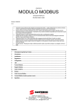
4376 en - 2013.08 / d Ready Stop Run Start Trip Local Reset LCL RMT AP ASCII Protocol RTU ON OFF Example: Address = 24 be g o t s ual i n se r a u m d This o the en t ive n Address +16 +8 +4 +2 +1 0 0 0 0 0 +16 +8 +4 +2 +1 ON Baud Rate Parity Timeout (seconds) ON 4800 9600 19200 38400 OFF OFF ON ON OFF ON OFF ON No Parity ODD EVEN 10 bit OFF OFF ON ON OFF ON OFF ON No Time Out 10 s 60 s 100 s OFF OFF ON ON OFF ON OFF ON MODBUS MODULE Communications module User Guide 0 0 0 0 0 General Information The manufacturer accepts no liability for any consequences resulting from inappropriate, negligent or incorrect installation or adjustment of the optional parameters of the equipment or from mismatching the starter with the motor. The contents of this guide are believed to be correct at the time of printing. In the interests of commitment to a policy of continuous development and improvement, the manufacturer reserves the right to change the specification of the product or its performance, or the content of the guide without notice. All rights reserved. No parts of this guide may be reproduced or transmitted in any form or by any means, electrical or mechanical including, photocopying, recording or by an information storage or retrieval system, without permission in writing from the publisher. Copyright: © August 2013 LEROY SOMER Issue D Contents 1. 2. 3. Introduction .......................................................................................................................................................4 Important User Information ..............................................................................................................................4 Installation .........................................................................................................................................................4 3.1 3.2 Installation Procedure ............................................................................................................................................................4 Physical installation................................................................................................................................................................4 4. Modbus Module Connection and Configuration ............................................................................................5 4.1 4.2 4.3 Adjustment .............................................................................................................................................................................5 Connection.............................................................................................................................................................................5 LEDs ......................................................................................................................................................................................6 5. 6. Master Configuration ........................................................................................................................................6 Modbus Functions ............................................................................................................................................6 6.1 6.2 6.3 6.4 6.5 Modbus Register ....................................................................................................................................................................7 Trip Codes .............................................................................................................................................................................9 Cyclic redundancy check (CRC)........................................................................................................................................... 10 Examples ............................................................................................................................................................................. 10 Modbus Error Codes ............................................................................................................................................................ 11 7. Modbus Control via Remote Keypad ............................................................................................................ 11 7.1 7.2 7.3 7.4 Grounding and Shielding...................................................................................................................................................... 11 Termination Resistors .......................................................................................................................................................... 11 RS-485 Data Cable Connection ........................................................................................................................................... 11 Remote Keypad RS-485 Network Connection Specifications ............................................................................................... 11 8. Specifications.................................................................................................................................................. 12 Modbus Module User Guide Issue D 3 www.leroy-somer.com 1. Introduction The Modbus Module can be used with Digistart D2 and Digistart D3 soft starters to allow the starter to be connected to a serial communications network using the Modbus RTU or AP ASCII protocols. 2. Important User Information Observe all necessary safety precautions when controlling the soft starter remotely. Alert personnel that machinery may start without warning. It is the installer's responsibility to follow all instructions in this manual and to follow correct electrical practice. Use all internationally recognised standard practice for RS-485 communications when installing and using this equipment. 3. Installation Remove mains and control voltage from the soft starter before attaching or removing accessories. Failure to do so may damage the equipment. C A UT IO N 3.1 Installation Procedure 1. Remove control power and mains supply from the soft starter. 2. Attach the module to the soft starter as illustrated. 3. Apply control power to the soft starter. 3.2 Physical installation 1. Fully pull out the top and bottom retaining clips on the module. 2. Line up the module with the comms port slot. 3. Push in the top and bottom retaining clips to secure the module to the starter. Figure 3-1 Attach the module to the starter 2 3 1 0 1 7 8 .B 1 Figure 3-2 Remove the module from the starter 0 3 5 5 0 .B Remove the module using the following procedure: 1. Take the module off-line. 2. Remove control power and mains supply from the soft starter. 3. Disconnect all external wiring from the module. 4. Fully pull out the top and bottom retaining clips on the module. 5. Pull the module away from the soft starter. 4 www.leroy-somer.com Modbus Module User Guide Issue D 4. Modbus Module Connection and Configuration 4.1 Adjustment Network communication parameters must be set on the Modbus Module. DIP switch settings take effect on the power-up of the Modbus Module via the soft starter. Figure 4-1 Adjustment switches 1 AP A S C II RT U OFF ON Protocol 7 0 +16 0 +8 0 +8 0 +4 0 +4 0 +2 0 +2 0 0 +1 2 A +1 ON OFF ON ON ON O FF ON N o P a ri t y ODD EVEN 1 0 b it OFF OFF ON ON OFF ON O FF ON N o T im e O u t 10 s 60 s 1 00 s OFF OFF ON ON OFF ON O FF ON 5 4.2 0 ON 384 00 4 B Baud rate 19 200 3 6 Address + 16 0 3 1 9 1 .B 6 4 800 96 00 OFF OFF Parity Timeout (seconds) DIP switch Example: Address = 24 Connection Figure 4-2 Modbus Module connections Digistart D2 Digistart D3 1 1 2 2 3 0 8 6 5 0 .A 0 8 6 4 9 .A 3 Digistart D2 Digistart D3 (Remote mode) CSL, DI2: Stop input DI2, +24V: Stop input DI3, +24V: Reset input Modbus Module – RS-485 serial port Modbus Module – RS-485 serial port RS-485 connection onto Modbus network RS-485 connection onto Modbus network Digistart D2: For the Modbus Module to accept serial commands, a link must be fitted across terminals CSL-DI2 on the soft starter. Digistart D3: Input links are required across the stop and reset inputs if the soft starter is being operated in Remote mode. In Local mode, links are not required. If the Starter Disable function is not required, change the setting of Pr 3A or connect a link across DI4, +24V. N O TE Digistart D3: Control via the serial communication network is always enabled in local control mode, and can be enabled or disabled in remote control mode (Pr 3O Comms in Remote). See the soft starter user manual for parameter details. Modbus Module User Guide Issue D 5 www.leroy-somer.com 4.3 LEDs The Network Status LED (1) indicates the state of the communications link between the module and the network. LED operation is as follows: Figure 4-3 Feedback LEDs Off No connection or soft starter not powered up On Flashing Communication active Communication inactive 0 3 1 9 3 .C 1 N O TE 5. If communication is inactive, the soft starter may trip if the Communications Timeout function has been set on the module. When communication is restored, the soft starter will require a Reset. Master Configuration For standard Modbus 11-bit transmission, the Master must be configured for 2 stop bits with No Parity and 1 stop bit for odd or even parity. For 10-bit transmission, the Master must be configured for 1 stop bit. In all cases, the Master baud rate and slave address must match those set on the Modbus Module DIP switches. The data polling interval must be long enough for the module to respond. Short polling intervals may cause inconsistent or incorrect behaviour, particularly when reading multiple registers. The recommended minimum polling interval is 300 ms. 6. Modbus Functions The Modbus Module supports the following Modbus functions: 03 Read multiple registers 06 Write single register 16 Write multiple registers Modbus broadcast functions are not supported. Digistart D2 soft starters (including Remote Keypad): Read multiple registers 40003 to 40008 Write single register 40002 Digistart D3 soft starters: Read multiple registers starting from 40003 up to a maximum of 119 register blocks. Single write register 40002 or multiple write registers 40009 to 40599. N O TE A multiple read across register boundary 40008/40009 will result in a Modbus Error code 05 at the Master. 6 www.leroy-somer.com Modbus Module User Guide Issue D 6.1 Modbus Register N O TE Some soft starters do not support some functions. Registers 40600 and above are not compatible with Digistart D2 Series soft starters. For Digistart D2, use registers 40002 to 40008. Table 6-1 Register addresses Register Description 40002 Command (single write) 40003 Starter state Bits 0 to 2 Details 0 to 7 0 to 7 0 to 7 0 to 2 3 to 7 0 to 7 0 to 7 To send a command to the starter, write the required value: 1 = Start 2 = Stop 3 = Reset 4 = Quick stop (coast to stop) 5 = Forced communication trip 6 = Start using Parameter Set 1 1 7 = Start using Parameter Set 2 1 Reserved 1 = Ready 2 = Starting 3 = Running 4 = Stopping (including braking) 5 = Restart delay (including temperature check) 6 = Tripped 7 = Programming mode 8 = Jog forward 9 = Jog reverse 1 = Positive phase sequence (only valid if bit 6 = 1) 1 = Current exceeds FLC 0 = Uninitialised 1 = Initialised 0 = Remote Operator communications are OK 1 = Remote Operator/Communications device fault See Trip Codes on page 9 Average 3-phase motor current (A) Motor 1 temperature (thermal model) Product parameter list version Product type code 3 Communication protocol between module and starter Manage soft starter programmable parameters. 0 to 5 6 to 8 9 to 15 Binary protocol version number Parameter list version number Product type code 3 Reserved Changed parameter number 0 to 7 40603 5 Changed parameter value 8 to 15 0 to 13 40604 Starter state 14 to 15 0 to 4 0 = parameters not changed 1 to 255 = index number of the last parameter changed Total number of parameters available in the starter Value of the last parameter that was changed, as indicated in register 40602 Reserved 0 = Reserved 1 = Ready 2 = Starting 3 = Running 4 = Stopping 5 = Not ready (restart delay, restart temperature check, run simulation, input A (DI4, +24V) not shorted) 6 = Tripped 7 = Programming mode 8 = Jog forward 9 = Jog reverse 1 = Warning 0 = Unintialised 1 = Initialised 3 to 7 0 to 3 4 5 6 7 40004 40005 2 40006 40007 Trip code Motor current Motor temperature Product information 40008 40009 4 40600 Serial Protocol Version Parameter management Single or multiple read or write Version 40601 40602 5 5 6 Modbus Module User Guide Issue D 7 www.leroy-somer.com Register Description Bits 7 8 9 40605 2 Current 40606 Current 40607 Motor temperature 40608 7 Power 40609 % Power factor 40610 Voltage 40611 2 Current 40612 2 Current 40613 2 Current 40614 40615 40616 40617 Reserved Reserved Reserved Parameter list version 40618 Digital Input state 40619 to 40631 Reserved 10 to 15 0 to 13 14 to 15 0 to 9 10 to 15 0 to 7 8 to 15 0 to 11 12 to 13 14 to 15 0 to 7 8 to 15 0 to 13 14 to 15 0 to 13 14 to 15 0 to 13 14 to 15 0 to 13 14 to 15 0 to 7 8 to 15 0 to 15 Details 0 = Local control 1 = Remote control 0 = Parameter(s) have changed since last parameter read 1 = No parameters have changed 5 0 = Negative phase sequence 1 = Positive phase sequence See Trip Codes on page 9 6 Average rms current across all three phases Reserved Current (% motor FLC) Reserved Motor 1 thermal model (%) Motor 2 thermal model (%) Power Power scale Reserved 100% = power factor of 1 Reserved Average rms voltage across all three phases Reserved Phase 1 current (rms) Reserved Phase 2 current (rms) Reserved Phase 3 current (rms) Reserved Parameter list minor revision Parameter list major version For all inputs, 0 = open, 1 = closed (shorted) 0 = Start 1 = Stop 2 = Reset 3 = Input A 4 = Input B 5 = Input C, if fitted 6 = Input D, if fitted 7 to 15 = Reserved Reserved 1 Ensure that the programmable input is not set to Motor Set Select before using this function. For models D3-1x-0053-B and smaller this value will be 10 times greater than the value displayed on the keypad. 3 Product type code: 4 = Digistart D2 8 = Digistart D3 4 See the relevant soft starter literature for a complete parameter list. The first product parameter is always allocated to register 40009. The last product parameter is allocated to register 40XXX, where XXX = 008 plus total number of available parameters in the product. 5 Reading register 40603 (Changed parameter value) will reset registers 40602 (Changed parameter number) and 40604 (Parameters have changed). Always read registers 40602 and 40604 before reading register 40603. 6 Bits 10 to 15 of register 40604 report the soft starter's trip or warning code. If the value of bits 0 to 4 is 6, the soft starter has tripped. If bit 5 = 1, a warning has activated and the starter is continuing to operate. 7 Powerscale functions as follows: 0 = multiply Power by 10 to get W 1 = multiply Power by 100 to get W 2 = Power is represented in kW 3 = multiply Power by 10 to get kW 2 N O TE If Pr 3A Input A Function for Digistart D3 is set to motor set select, this will cause a conflict with motor set selection via serial communications. 8 www.leroy-somer.com Modbus Module User Guide Issue D 6.2 Trip Codes Table 6-2 Trip messages Trip Code 1 2 3 4 5 6 7 8 10 11 12 13 14 15 16 17 201 23 24 26 27 28 29 30 31 32 332 35 36 37 381 391 401 411 421 431 45 46 47 48 255 1 2 Description Digistart D2 Digistart D3 Excess start time Motor overload (thermal model) Motor thermistor Current imbalance Frequency (Mains supply) Phase sequence Instantaneous overcurrent Power loss / Power circuit Heatsink overtemperature Motor Connection Tx Input trip FLC too high (FLC out of range) Unsupported option (function not available in inside delta) Starter communication (between module and soft starter) Network communication (between module and network) Internal fault x (where x is the fault code detailed in the table below) Ground fault Parameter out of Range Input B trip L1 phase loss L2 phase loss L3 phase loss L1-T1 shorted L2-T2 shorted L3-T3 shorted Motor 2 overload (thermal model) Time-overcurrent (Bypass overload) Battery/clock Thermistor circuit RTD/PT100 A RTD/PT100 B RTD/PT100 C RTD/PT100 D RTD/PT100 E RTD/PT100 F RTD/PT100 G RTD/PT100 X Circt Analog input trip Overpower Underpower No trip Available with Digistart D3 only if the appropriate option card is fitted. For Digistart D3, time-overcurrent protection is only available on internally bypassed models. Modbus Module User Guide Issue D 9 www.leroy-somer.com 6.2.1 Internal Fault x The table below details the internal fault code associated with trip code 17. Table 6-3 Internal fault X Internal fault 70 to 72 73 74 to 76 77 to 79 80 to 82 83 84 to 98 6.3 Message displayed on the keypad Current Read Err Lx ATTENTION! Remove Mains Volts Motor Connection Tx Firing Fail Px VZC Fail Px Low Control Volts Internal fault X Contact your local supplier with the fault code (X). Cyclic redundancy check (CRC) The CRC is a 16bit cyclic redundancy check using a polynomial with a value A001. The 16bit CRC is appended to the message and transmitted LSB first. The CRC is calculated on all the bytes in the frame. For further Modbus information, including the CRC calculation, refer to the Modbus protocol specifications available at http://www.modbus.org/specs.php. 6.4 Examples Command: Start Message In Out Starter Address 20 20 Function Code 06 06 Register Address 40002 40002 Data 1 1 CRC CRC1, CRC2 CRC1, CRC2 Starter status: Running Message Starter Address In 20 Out 20 Function Code 03 03 Register Address 40003 2 Data 1 xxxx0011 CRC CRC1, CRC2 CRC1, CRC2 Trip code: Motor overload Message Starter Address In 20 Out 20 Function Code 03 03 Register Address 40004 2 Data 1 00000010 CRC CRC1, CRC2 CRC1, CRC2 Download parameter from starter Digistart D3: Read parameter 3 (Pr 1C) Locked Rotor Time, 10 seconds Message Starter Address Function Code Register Address In 20 03 40011 Out 20 03 2 Data 1 10 CRC CRC1, CRC2 CRC1, CRC2 Upload parameter to starter Digistart D3: Write parameter 12 (Pr 2H), Stop Mode, set = 2 'Adaptive Control' Message Starter Address Function Code Register Address In 20 06 40020 Out 20 06 40019 Data 2 2 CRC CRC1, CRC2 CRC1, CRC2 Upload multiple parameters to starter Digistart D3: Write Parameters 6, 7, 8 (Prs 2B Current Limit, 2C Initial Current, 2D Start Ramp Time). Set to values of 350%, 300%, 15 seconds respectively. Message Starter Address Function Code Register Address Data CRC In 20 16 40014,3 350, 300, 15 CRC1, CRC2 Out 20 16 40014,3 350, 300, 15 CRC1, CRC2 N O TE This function can only be used to upload consecutive parameters. The Register Address data indicates the number of parameters to be uploaded, and the register address of the first parameter. N O TE Parameter information can only be uploaded/downloaded from Digistart D3 starters. 10 www.leroy-somer.com Modbus Module User Guide Issue D 6.5 Modbus Error Codes Table 6-4 Error codes Code 01 02 03 04 05 06 07 08 09 10 N O TE 7. Description Illegal function code Illegal data address Not readable data Not writable data Data boundary fault Invalid command code Illegal parameter read Illegal parameter write Unsupported command Local communication error Example Function other than 03 or 06 Register number invalid Register not allowed for data reading Register not allowed for data writing Multiple data transfer across data boundary or data size more than 125 eg writing "6" into 40003 Invalid parameter number Invalid parameter number, read only, or hidden parameter Sending a serial command to Digistart D3 with Pr 3O = Disable Control in RMT. Communication error between Modbus slave and starter Some of the above codes are different from those defined in the Modbus Application Protocol Specification available on www.modbus.org. Modbus Control via Remote Keypad The Modbus Module can be used to connect a Remote Keypad to the soft starter, enabling control via an RS-485 serial communications network. See the Remote Keypad instructions for details. 7.1 Grounding and Shielding Twisted pair data cable with ground shield is recommended. The cable shield should be connected to the GND device terminal at both ends and one point of the site protective ground. 7.2 Termination Resistors In long cable runs prone to excessive noise interference, termination resistors should be installed between the data lines at both ends of the RS-485 cable. This resistance should match the cable impedance (typically 120 Ω). Do not use wire wound resistors. Figure 7-1 Installation with termination resistors 2 3 0 32 5 0. B 1 Network master RS-485 Remote Keypad RS-485 Soft starter RS-485 7.3 RS-485 Data Cable Connection Daisy chain connection is recommended. This is achieved by parallel connections of the data cable at the actual device terminals. 7.4 Remote Keypad RS-485 Network Connection Specifications Input impedance: Common mode voltage range: Input sensitivity: Minimum differential output voltage: Modbus Module User Guide Issue D 12 kΩ - 7 V to + 12 V ± 200 mV 1.5 V (with max loading of 54 Ω) 11 www.leroy-somer.com 8. Specifications Enclosure Dimensions ........................................................................................................................... 40 mm (W) x 166 mm (H) x 90 mm (D) Weight ..................................................................................................................................................................................... 250 g Protection .................................................................................................................................................................................. IP20 Mounting Spring-action plastic mounting clips (x 2) Connections Soft starter ......................................................................................................................................................... 6-way pin assembly Network ................................................................................................... 5-way male and unpluggable female connector (supplied) Maximum cable size ........................................................................................................................................................... 2.5 mm2 Settings Protocol ....................................................................................................................................................... Modbus RTU, AP ASCII Address range ....................................................................................................................................................................... 0 to 31 Data rate (bps) ......................................................................................................................................... 4800, 9600, 19200, 38400 Parity .......................................................................................................................................................... None, Odd, Even, 10-bit Timeout ................................................................................................................................................. None (off), 10 s, 60 s, 100 s Certification C ........................................................................................................................................................................... IEC 60947-4-2 CE .......................................................................................................................................................................... IEC 60947-4-2 RoHS ................................................................................................................................. Compliant with EU Directive 2002/95/EC 12 www.leroy-somer.com Modbus Module User Guide Issue D Modbus Module User Guide Issue D 13 www.leroy-somer.com 14 www.leroy-somer.com Modbus Module User Guide Issue D Modbus Module User Guide Issue D 15 www.leroy-somer.com MOTEURS LEROY-SOMER 16015 ANGOULÊME CEDEX - FRANCE 338 567 258 RCS ANGOULÊME Simplified Joint Stock Company with capital of 65,800,512 € www.leroy-somer.com