1
Setting up levels for best performance
CDR‑1 Remote Control Plates
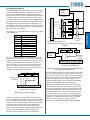
To optimise signal levels through the DCM‑1 and obtain
the best signal-to-noise performance, we recommend the
following procedure is followed for adjusting music and
paging levels.
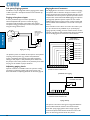
Most audio systems based around the DCM‑1 will include
CDR‑1 remote control plates to permit in-zone selection of
music source and level.
1. Choose a suitable music source and set the INPUT
GAIN of its input so the signal is peaking within the
target area, via the Music menu in Installer mode.
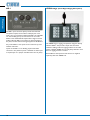
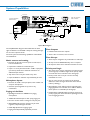
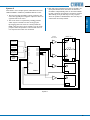
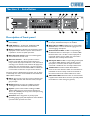
An overview of the CDR‑1 can be found at page 8 and notes
on installation and wiring at page 19.
2. Route this music source to a convenient Zone and
adjust the LEVEL in this zone to 0dB (i.e. maximum)
again via the Music menu.
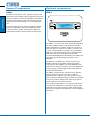
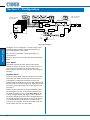
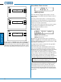
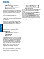
The backlight in the CDR‑1’s display automatically times-out
after a few seconds (the actual time is programmable) to
minimise power consumption. The display is “woken up” by
pressing the Zone button, and the unit confirms the Zone
it has been assigned to, either as Zone n, or by name if the
zones have been renamed (see diagram below).
4. Set the paging microphone level control for that zone to
maximum.
5. Adjust the Paging Mic Gain or CDPM Gain whilst
making an announcement to match the level of the
announcement with the desired maximum level of the
music.
6. Adjust the paging microphone for preferred
announcement level in the zone.
7. Repeat step 1 for other music sources.
8. Repeat steps 2,3 and 6 for the other zone outputs.
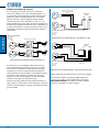
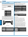
Press Zone button to "wake up" display
Zone
i
Current Zone
Reception
-
h
+
Configuration
3. Adjust the gain of the power amplifiers feeding the
loudspeakers in that Zone so that the sound level in the
Zone is as loud as is likely to be required.
User Operation
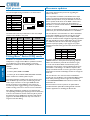
CDR‑1 User Mode: i) wake-up display
Zone
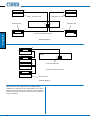
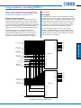
Display Contrast adjustment
i
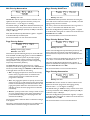
The display should be easily readable in most normal
situations. If it is necessary to alter the display contrast
to improve readability under extreme ambient lighting
conditions, remove the top cover (8 screws) and locate the
trimpot at the left-hand end of the PCB mounted directly
behind the front panel. This can be adjusted as required.
Replace the cover using the same screws.
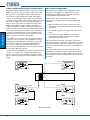
-
i h
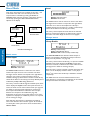
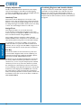
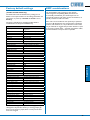
keys select line input (music source)
Music Server
Level |||||||||||||||
and
h
+
keys adjust music level
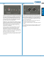
CDR‑1 User Mode: ii) adjustment display
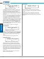
The CDR‑1 will change to the adjustment display shown at
ii) above after approx. 10 seconds, or immediately if any of
the other four buttons are pressed. The i and h buttons can
now be used to scroll through the inputs available to the
zone. Only those inputs which have been enabled in the
DCM‑1 menu system at Routing > Input Enable will
be displayed. The + and – buttons adjust the volume.
DCM‑1 User Manual v1.0
45