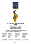
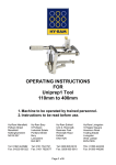
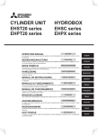
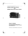
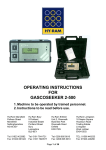
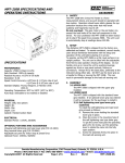
1
OPERATING INSTRUCTIONS
FOR
Clegg Impact Soil Tester
20 Kgs
1. Machine to be operated by trained personnel.
2. Instructions to be read before use.
Hy-Ram Mansfield
Pelham Street
Mansfield
Nottinghamshire
NG18 2EY
Hy-Ram Bury
9 Portland
Industrial Estate
Portland Street
Bury
Lancashire
BL9 6EY
Hy-Ram Enfield
Unit 2, Riverwalk
Business Park
Riverwalk Road
Enfield
EN3 7QN
Hy-Ram Livingston
18 Napier Square
Houstoun Road
Trading Estate
Livingston
West Lothian
EH54 5DG
Tel: 01623 422982
Fax: 01623 661022
Tel: 0161 7641721
Fax: 0161 7620577
Tel: 0208 805 8010
Fax: 0208 805 6010
TEL: 01506 440233
Fax: 01506 440266
Page 1 of 23
Hy-Ram Engineering Co Ltd has a policy of continuous improvement in product quality and
design. Hy-Ram Engineering Co Ltd therefore reserves the right to change the
specification of its models at any time, without prior notice.
Important!
This manual forms a part of the product to which it relates. It should be kept for the life of
the product. Any amendments issued by Hy-Ram Engineering Co Ltd should be
incorporated in the text. The manual should be passed to any subsequent holder or user
of this product.
HEALTH & SAFETY
UNLOADING PRECAUTIONS
The 20 Kg Clegg Impact Soil Tester is supplied packed in a crate designed to locate the
20Kg Hammer within the Guide Tube. During transit, the foam inserts in the crate help
prevent the Hammer moving within the Guide Tube. Exercise extreme caution when
unloading the Tester from the crate as it may be possible for the Hammer to become
dislodged from its rest position during the unloading manoeuvre.
INTRODUCTORY HANDLING PRECAUTIONS
The 20 Kg Clegg Impact Soil Tester requires careful handling at all times during
preparation and use to ensure safe working and freedom from accidents. A few
commonsense precautions should always be observed. Use extreme care when lifting and
handling the Tester. To avoid straining the back do not attempt to lift the assembled tester
without assistance. Keep the feet clear of the Hammer when it is being loaded into the
guide tube and when it is released during testing and operation of the equipment.
INTRODUCTION
This manual describes the 20 Kg Clegg Impact Soil Tester type CIST/883. The CIST/883 is
used to test the surface conditions of earthwork materials and established paved surfaces.
Testing involves dropping the 20 Kg Test Hammer five times at each test location. When
the Hammer is strikes the surface under test the accelerometer in the Hammer generates
an electrical pulse. The magnitude of the pulse depends upon the surface characteristics.
The instrument records the accelerometer pulse and displays readings in terms of Impact
Values (IV) with a maximum reading scale of 101 IV. Clegg Hammer Modulus display is
also available. The test data can be stored in the CIST/883 Readout unit and this can be
downloaded wirelessly using Bluetooth® to a Microsoft Windows® PC running the Data
Handler software provided in this consignment.
Page 2 of 23
Page 3 of 23
Page 4 of 23
Page 5 of 23
The CIST/883 Readout Unit
The CIST/883 Readout Unit is the measuring electronics and means of display of the
measured results.
This is a separately-housed self-contained instrument. When the Tester is being prepared
for carrying out measurements, the CIST/883 Readout Unit is placed in position on the
Mounting Block (paragraph 3.1.3 above) and connected to the Hammer via the Connector
Cable.
The Connecting Cable
The connecting cable is connected between the socket in the T Lifting Handle and the
CIST/883 Readout Unit.
Both ends of the cables are inserted into their respective sockets by lining up the slots of
the cable connectors over the pins of their mating connectors, pressing in and turning to
the right through 90 degrees until the connectors lock in place.
Ensure the cable and the end connectors are kept clean and dry. Wipe off residual
moisture at the end of every testing session.
The Operational Check Ring
The Operational Check Ring is used to check the basic functioning of the CIST/883 Tester.
Test the system every month by dropping the Hammer onto the ring through the Guide
Tube. The Operational Check Ring is an annular ring of high density plastic material.
To obtain a reading from the Operational Check Ring place it on a hard surface centrally in
the Guide Tube. Drop the Hammer on to it in the same way a normal test is carried out.
The Operational Check Ring IV will be displayed on the CIST/883 Readout Unit.
The readings from the Operational Check Ring vary and depend upon the hardness of the
ground onto which the Operational Check Ring is placed, temperature and humidity. A
reading of approximately 18 to 24 is achieved at Hyram premises.
The Operational Check Ring is not to be used a means to calibrate the system. Only use it
for quick operational checks. Failure to achieve a reading near the range indicated may
mean the equipment is faulty.
Page 6 of 23
Page 7 of 23
AFTER UNPACKING, PREPARING THE 20 Kg CLEGG IMPACT SOIL TESTER
FOR TESTS
Check that the underside of the 20 Kg Tester Base Plate is clean. Stand the Guide Tube
Assembly upright on a clean and level surface.
Ensure the Hammer Support Pin is centrally located within the circular hole in the bracket
on the ‘T’ Hammer handle.
The Hammer Support Pin should be settled in the grooves* in the top edge of the Guide
Tube. The grooves in the Guide Tube are offset to allow the Hammer to hang centrally.
The Hammer is lifted by the Hammer Support Pin such that the Hammer base is clear of
the ground. See Picture 6 below.
Picture 6 – 20 Kg Hammer Supported by Hammer Support Pin in the Guide Tube
Slots
*Note:- In later designs two holes located on adjacent sides of the Guide Tube are used to
support the Hammer Support Pin.
Ensure that the internal bore of the Guide Tube Assembly is clean and free from
obstructions.
Loosen the screw fixing the Mounting Block and position it at a suitable viewing height
clear of the tube. Tighten the screw. See Picture 7 below.
Picture 7 – Tighten the Screw to Secure the Mounting Block
Page 8 of 23
Clip the Digital Readout Unit on to the Mounting Block. Plug the connecting cable to the
coaxial connector on underside of the Digital Readout Unit. Ensure that the connector plug
locks into place on the socket. See Picture 8 and Picture 9 below.
Picture 8 – Clip Digital Readout to Adjustable Mounting Block
Picture 9 – CIST/883 Readout BNC Connector
Connect the other end of the Connector Cable into the socket on the T-piece of the
Hammer handle. See Picture 10 below.
Picture 10 – Connector cable in T-Handle
The complete assembly can now be pulled along.
Note: Earlier models use two support grooves for the Hammer Support Pin at the top of
the Guide Tube. This arrangement does not secure the Hammer in the Guide Tube and
care should therefore be exercised when moving the Tester around to ensure that the
Hammer does not become detached from the Guide Tube.
THE CIST/883 DIGITAL READOUT UNIT DESCRIPTION
SWITCHING ON THE CIST/883 READOUT UNIT & OBSERVING BATTERY LEVEL
Page 9 of 23
The CIST/883 Readout Unit is supplied with two ‘AA’ sized batteries. Check these have
been installed in the instrument.
Switch On: Press the ‘ON’ Button
Press and then release the ‘ON’ button on the side of the Digital Readout Unit. See Picture
11 below.
Picture 11 – CIST/883 Readout Unit On/Off Button
Battery Level Indication
Battery life is dependant upon the battery type, frequency of system use, the interval
between use and ambient temperature.
Maximum battery current is drawn when the CIST/883 Readout unit is Bluetooth®
connected to the PC. Assuming this is a rare event an 18 month battery life can be
expected based upon the use of two ‘AA’ alkaline type batteries.
When the CIST/883 Readout Unit is first switched on the battery status of the two ‘AA’
batteries is shown on an ‘AA’ battery level gauge display on the LCD display for 3 seconds.
See Pictures Picture 12 and Picture 13 below.
Picture 12 – ‘AA’ Battery Level: Good
Picture 13 – ‘AA’ Battery Level: Lower But Still Acceptable for System Operation
The vertical bar shown in the battery level gauge display moves from the right to left as
the two ‘AA’ batteries gradually become more discharged.
Page 10 of 23
Note: When the battery capacity is nearly exhausted the CIST/883 Readout Unit will
display ‘BATTERY!’ after each drop test. This indicates both batteries should be
replaced using fresh batteries, both of the same type.
When the batteries are totally exhausted the CIST/883 Readout Unit will display ‘BAT
FAIL’ after a drop test. The unit will then switch off. Both batteries should be changed
immediately.
After the battery level display shown in Picture 12 and Picture 13 above the LCD display
will show ‘000 IV 0’ as in Picture 14 below.
Picture 14 – CIST/883 LCD Display Initial Display
Automatic Switch-Off and Manual Switch-Off
A timer circuit in the Digital Readout Unit switches the unit OFF automatically
approximately 5 minutes after the last signal input hammer drop.
The Digital Readout Unit can also be switched off manually at any time. To do this press
and hold the ‘ON’ button for about 3 seconds until the display shows OFF! Release the
button and the Digital Readout Unit will switch off.
THE DIGITAL READOUT UNIT DISPLAY
Reading from left to right on the Display of the Digital Readout Unit, the first 3 digits are
the Impact Value (IV); the next 2 characters are the symbol IV; the final digit is the
number of times the Hammer has been dropped, cycling through 1 to 5 after which the
drop number is repeated. A reading of 25 IV and drop number 5 is shown Picture 15
below.
Picture 15 – LCD Showing 25 IV and Drop Number 5
The Display covers a range of Impact Value (IV) from 003 to 101 IV in increments of 1 IV.
If an Impact Value (IV) of greater than 101 is obtained, the display will indicate STOP
NOW! Further tests at this site location should be discontinued. However, in practice, the
range of IV likely to be encountered would typically be from about 5 IV (soft ground) to 80
IV (hard ground).
Display Zeroing
The Digital Readout Unit display can be reset to zero at any time during a test run. This is
achieved by briefly pressing the ‘ON’ button.
Automatic Zeroing Display
The CIST/883 Readout Unit automatically resets the display to zero and the drop number
to zero when the interval between successive hammer drops exceeds 17 seconds. This is
to ensure that inadvertent readings are not shown when testing is prematurely stopped.
Page 11 of 23
Ensure therefore that testing at each location is carried out by dropping the hammer at
intervals less than 17 seconds.
Clegg Hammer Modulus Display
When the CIST/883 Readout Unit has been configured to display the Clegg Hammer
Modulus (CHM) the CHM is displayed 3 seconds after the 5th Hammer drop reading.
Example: For a fifth drop Impact Value (IV5) of 25 IV the Clegg Hammer Modulus is
calculated as 144 MPa and displayed on the LCD as shown in Picture 16 below.
Picture 16 – Example CHM Calculated as 144 MPa for a 5th Drop IV of 25 IV
Note:- The CHM will only be displayed providing the following two situations are met:1) The TREND limits during the 5 drops in a test, shown in table Table 1
2) The CHM option has been enabled in the CIST/883 Readout Unit. See description of
how to enable/disable the CHM facility.
Test Procedure Using the Clegg Impact Soil Tester
The 20 Kg Clegg Impact Soil Tester is intended for use on flexible pavements or on
equivalent materials or on deeper than standard lifts for earthworks, roadworks or airfield
runways and aprons. It is not advisable for use directly on concrete or on materials of
similar hardness.
The suggested test procedure is as follows:
• Ensure the Hammer strike face is clean and free from material build-up and that the
hammer mass and the inside of the Guide Tube are clean so as not to impede the free fall
of the Hammer.
• Select a test location and brush the surface clear of loose material and debris - scuffing
with the foot is usually adequate.
• Place the Clegg Impact Soil Tester (CIST) vertically in position, ensuring that the Guide
Tube sits squarely on the surface under test. To check this, place both feet on the foot
plate at the base of the Guide Tube to ensure that the vertical position of the Guide Tube
is maintained. If the Guide Tube rocks in this position, move the CIST to a location nearby.
• Lift the Hammer slightly and whilst holding it, remove the Hammer Support Pin. Stow it
in the hole located in the Adjustable Mounting Block to keep it clear of operations.
Carefully lower the Hammer back in the Guide Tube, letting it settle on the surface under
test. Keep both feet on the foot plate at the base of the Guide Tube to maintain stability of
the CIST.
• Press and then release the ON button on the Digital Readout Unit. The Display should
read 000 IV 0.
Page 12 of 23
• Raise the Hammer until the top surface of the mass is level to within ± 10mm of the top
of the Guide Tube. (See Picture 17 below). This sets the nominal drop height to 310 mm
(12.2”). If preferred, steady the CIST by holding the top of the Guide Tube handle. If
necessary get assistance for this operation. Make sure that the Hammer is positioned
centrally in the Guide Tube, minimising the contact between the Hammer and the inside
wall of the Guide Tube.
Picture 17 – Keep Top of Hammer Level with Top of Guide Tube (Within ±
10mm)
•
Release the Hammer from the set height of drop, allowing it free fall. Note the Impact
Value (IV) displayed on the Digital Readout Unit and check the drop number which
should show ‘1’. The Hammer should be allowed to fall cleanly else the reading may be
affected.
•
Next, without moving the Guide Tube, repeat the raising and dropping of the Hammer
four more times, noting the Impact Values at each drop. The Impact Value observed at
the fourth drop should be recorded as the relevant IV, provided that the fifth value is
not significantly different from the fourth drop value. When the 5th drop has taken
place, if the readout has been configured by the user to display Clegg Hammer
Modulus (CHM) the readout will display the 5th drop Impact Value (IV) and then it will
display the CHM of the 5th drop.
•
The CIST/883 Readout Unit automatically resets the display to zero and the drop
number to zero when the interval between successive hammer drops exceeds 17
seconds. This is to ensure that inadvertent readings are not shown when testing is
prematurely stopped. Ensure therefore that testing at each location is carried out by
dropping the hammer at intervals less than 17 seconds.
•
The Digital Readout Unit will switch off automatically 5 ½ minutes after the last
hammer drop.
•
On completion of tests at any location, raise the Hammer whilst it is in the Guide Tube
for access to the locking pin block on the ‘T’ Hammer handle. Re-insert the locking pin.
Gently lower the Hammer, locating the locking pin in the slots or side holes in the
Guide Tube.
Checking the Clegg Impact Soil Tester Performance using the Operational
Check Ring
Rudimentary system checks can be made by using the Operational Check Ring, hereinafter
referred to as the Ring. The Impact Value (IV) is shown together with the serial number of
the instrument on the rim of the Ring supplied with the system. The marked value is
typical and the actual value obtained during a test varies depending upon the surface type
Page 13 of 23
the Ring is placed upon and the manner in which the hammer lands onto the Ring. A
typical Ring IV value at the manufacturer’s is about 22 IV when the hammer lands evenly
on the Ring. As the Ring material is not truly representative of an actual soil surface
occasionally erroneous readings of around 10 IV may be displayed when the hammer base
falls unevenly onto the Ring. The calibration certificate shows 20 x evenly loaded hammer
drop IV’s only. To carry out the test using the Ring, proceed as follows: • Select a test location which should be a clean, horizontal, level and hard base such as
concrete. Brush the surface clear of loose material and debris.
• Switch the Digital Indicator Unit ON and check that the display reads 00 IV 0.
•Place the Clegg Impact Soil Tester (CIST) vertically in position, ensuring that the Guide
Tube sits squarely on the surface under test. To check this, place both feet on the foot
plate at the base of the Guide Tube to ensure that the vertical position of the Guide Tube
is maintained. If the Guide Tube rocks in this position, move the CIST to a location nearby.
• Lift the Hammer slightly and remove the Hammer locking pin, stowing it in the mounting
hole in the support bracket. Place both feet on the foot plate at the base of the Guide
Tube to maintain stability of the CIST. Now lift the Hammer completely out of the Guide
Tube and stand it nearby, ensuring that the Connector Cable is not stressed.
• Place the Ring centrally inside the Guide Tube on the surface at the base of the Guide
Tube. Lift the Hammer back and steady it on the rim of Guide Tube. Place both feet on the
foot plate at the base of the Guide Tube to maintain stability of the CIST. Carefully lower
the Hammer into the guide tube until the top of the Hammer mass is level with the top of
the Guide Tube.
• Extreme care is needed at these next stages of the test procedure to ensure
complete safety of the operation.
• Maintain the Hammer suspended at the level attained in the previous stage and transfer
one hand from the Hammer to the grip on the handle of the Guide Tube to steady it. If
necessary get another person to steady the Guide Tube.
• Release the Hammer to let it free-fall on to the Ring. Because of the high elasticity of the
Ring material, the Hammer will bounce in the Guide Tube before settling on the Ring. Note
the IV reading on the display of the Digital Readout Unit.
• Repeat the test two or three times to ensure consistency of results. Before repeating the
test, each time lift the Hammer clear of the Guide Tube observing the previously listed
safety precautions and check that the Ring remains resting on the surface at the base of
the Guide Tube. Ensure that at each drop, the Hammer falls cleanly without contacting the
inner wall of the guide tube.
• Ignore unusually low readings caused by an uneven landing of the hammer onto the
Ring.
• If the Impact Values obtained during the above tests differ more than ± 4 digits, the
calibration of the CIST may have changed and the measurement accuracies could be
impaired. Under these circumstances it may be necessary to return the Clegg Impact Soil
Tester to Hyram for inspection, possible repair and re-calibration.
Page 14 of 23
• On completion of the tests, raise the Hammer sufficiently whilst it is in the Guide Tube to
gain access to the locking pin bracket on the Hammer handle. Re-insert the locking pin.
Gently lower the Hammer, turning it to locate the locking pin in the slots or side holes in
the Guide Tube.
HOW TO FIT BATTERIES IN THE CIST/883 DIGITAL READOUT UNIT
CIST/883 READOUT UNIT BATTERY FITTING
The CIST/883 Readout Unit operates from 2 x 1.5V ‘AA’ size batteries that are located in
an IP67 rated battery compartment located at the base of the CIST/883 Readout Unit.
It is unlikely that the batteries will require replacement between routine re-calibration
intervals as the typical battery life is in excess of 12 months. However if battery access is
required it is necessary to remove the circular battery cap located under the yellow
protection plate at the base of the CIST/883 Readout Unit shown in Picture 36 below. The
procedures are explained below.
Picture 36 – CIST/883 Battery Cap Protected by Yellow Plate.
To fit new batteries, carry out the following procedures in order:a) Start and finish the procedures below in a dry and clean environment.
b) Unclip the CIST/883 Readout Unit from its Readout Bracket and remove the connecting
cable.
c) The battery cap is protected by a rectangular yellow cover plate shown in Picture 36
above. The plate is held secured using four Button Head screws. Remove the yellow cover
plate by unscrewing all four Button Head screws using the 2mm Allen Key provided. Note
the positions of the various washer combinations used in the assembly prior to unscrewing
each Button Head screw as they will be required when re-securing the plate. See Picture
37 below.
Page 15 of 23
Picture 37 – Protection Cover Removed Exposing Battery Cap
d) When the yellow cover plate has been removed carefully unscrew the circular battery
cap shown in Picture 37 above by turning it anti-clockwise about 40 degrees. A spring
inside the battery compartment will push out the first battery and may try to flick the
battery cap away due to the spring action.
Be careful not to lose the battery cap when it is pushed by the spring!
e) Angle the CIST/883 Readout Unit down so that the second battery is ejected.
f) Insert two new batteries of the same type ensuring that both their positive connections
face outwards. No damage will result if they are inserted the wrong way round but the
unit will not operate. See Picture 38 below.
Picture 38 – When Battery Cap Removed Batteries Can Be Replaced
g) Take care when re-securing the battery cap and ensure the two flange prongs on the
battery cap locate into the corresponding slots in the Readout opening. Ensure the battery
cap is rotated clockwise sufficiently to provide its IP67 rated seal. A mechanical end stop
provides tactile feedback when the cap is sufficiently tightened but DO NOT over tighten.
h) The battery cap provides waterproofing properties but it must be protected by the
yellow cover when the equipment is in service or during shipment. The yellow cover
prevents inevitable shock loads experienced during handling from damaging the terminal
prongs inside the battery cap. The yellow cover also stops inadvertent tampering of the
battery cap.
i) Ensure that when the batteries are replaced the full complement of screws and washers
comprising the yellow plate assembly are re-used in the correct order. See Picture 39
below. If items are lost spares can be obtained from Hyram.
Page 16 of 23
Picture 39 – Battery Cover M3 Stainless Button Head Screw & Washer Assembly
j) Re-secure the CIST/883 Readout Unit to the Readout Bracket using the pair of clamps.
‘AA’ BATTERY TYPES
Use two ‘AA’ size batteries in the CIST/883 Readout Unit. Each ‘AA’ battery should be of
the same type and should produce an off load voltage of nominally 1.5 Volts. A
comparison of battery type is provided here:
Alkaline
If rechargeable batteries are not available or required, alkaline batteries are economical.
Battery types such as the Duracell Ultra, Energizer Advanced Formula, or Kodak Photolife
provide good service although unbranded types are also suitable.
There is not much difference in battery capacity from brand to brand. They all perform
similarly, despite the battery manufacturers' claims. The spread between the best and
worst alkaline types is in the region 10-15%. Generally, regular unbranded alkaline types
provide sufficiently good service and are widely available.
Nickel-Metal Hydride (NiMH)
If rechargeable batteries are required Nickel-Metal Hydride (NiMH) is the preferred option
over the obsolete Nickel Cadmium type (NiCad). NiMH types have a higher capacity than
NiCad batteries and they suffer less from memory effect. However, NiMH batteries have a
higher selfdischarge rate and will be exhausted in a few months if not re-charged.
Lithium
Lithium batteries are more powerful but they are usually more expensive to purchase
compared to Alkaline types. They are not rechargeable. They are toxic and should be
disposed of properly at the end of their life in a hazardous waste facility.
BATTERY LIFE AND BATTERY LEVEL INDICATION
Battery life is dependant upon the battery type, frequency of system use, the interval
between use and ambient temperature.
Maximum battery current is drawn when the CIST/883 Readout unit is Bluetooth®
connected to the PC. Assuming this is a rare event an 18 month battery life can be
expected when using two ‘AA’ alkaline type batteries based upon intermittent usage.
Battery level indication is displayed for the first 3 seconds after the unit is switched on.
Page 17 of 23
DO NOT LEAVE THE BATTERIES IN THE CIST/883 READOUT UNIT FOR LONG
PERIODS!
If the CIST/883 Readout Unit is to be left for several months without use the batteries
should be removed from the Readout otherwise corrosion from the batteries may cause
damage to the internal electronics.
Care of Equipment
Do not allow sharp edged objects to fall onto or press into the display window of the
CIST/883 Readout Unit as the clear window may crack or puncture. A damaged display
window may affect the sealing integrity of the CIST/883 Readout Unit.
Care must be taken regarding the coaxial cable and the BNC connectors. Avoid kinks or
overstressing the cable.
Ensure that the BNC connectors on the cable, Hammer and CIST/883 Readout Unit are
kept clean and dry.
In standing the instrument upright, take the following precautions:
• Ensure the Hammer Locating Pin is in place if left unattended,
• Ensure it does not topple on uneven or rough ground,
• Ensure it does not get knocked over accidentally.
• Ensure the wheels on the Guide Tube are not banged down hard on the ground during
unloading or manoeuvring. This can damage the wheels and/or the axle studs.
Exercise common sense when it is raining regarding use. Do not let the CIST/883 Readout
Unit become excessively wet and always dry the unit after use. Ensure the connectors and
cable connections are kept dry after use.
Do not repeatedly drop the hammer onto uneven hard ground or stones. This can cause
weakness in the weld at the base of the T handle caused by rapid side ways acceleration
jerks of the hammer mass as it comes to rest.
Clean and dry the instrument as necessary, especially before storage.
Clean and dry the instrument as necessary, especially before storage. Clean any remnants
of soil build up from the base of the cylindrical hammer prior to use and before storage.
To protect against any possible battery leakage, remove the two ‘AA’ batteries from the
CIST/883 Readout Unit if the Tester is to be left in storage.
15 Frequently Asked Questions
AT THE END OF A TEST IS THE OPERATOR PROMPTED TO SAVE OR DISCARD THE
RESULT AND THEN MOVE ON TO THE NEXT TEST?
The result is automatically saved if the operator completes a 5-drop test. If he wants to
abandon the saving, he just stops dropping the hammer for more than 17 seconds. After
17 seconds the reading on the unit clears to zero and the previous drops in the test are
automatically deleted from memory.
Example:- the user completes 3 drops in quick succession (or within 17 seconds of each
hammer drop). His mobile phone rings just as he is about to start the 4th drop. He puts
down the Tester and answers his phone. The conversation lasts longer than 17 seconds
and he finishes his call. He then goes back to the Tester and the display will have reset to
Page 18 of 23
zero. This means he has to start his run of 5 drops again. This auto zeroing is present to
help reduce the number of partial test results that may otherwise occur in the stored data.
So, the user does not have to press any extra buttons to save the data. It is automatically
saved if he completes 5 drops because the set of 5 drops is a complete data set. If he
wants to abandon a data set then he stops dropping the hammer and in 17 seconds the
display zeroes. Alternatively he can briefly press the ‘On’ button at the side of the readout
and this also clears the display and removes the previous drops in a 5-drop test.
Also note that the Readout Unit can be set to not store data by configuring it using the
Data Handling Software. This means it will not store any data at all until enabled again by
the software.
WOULD THE OPERATOR WITHOUT A PC KNOW IF THERE ARE RESULTS IN
MEMORY BEFORE USING THE UNIT AND WITHOUT LINKING IT TO A PC?
No, the user would not know if there are results in memory already. This should not be a
problem though because firstly there is sufficient flash memory capacity in the Readout
Unit to hold up to 9999 tests (49,995 hammer drops) and it is extremely unlikely the
memory will be used up. Secondly the user will be able to identify his set of data when
downloaded into the PC because each set of data has the time and date.
Example:- User 1 carries out 50 tests (250 drops) on Monday and he then downloads his
data to the PC. However he forgets to clear the stored data in the readout. On Tuesday
user 2 carries out 100 tests (500 drops). When user 2 downloads the data to the PC, there
will be 150 tests downloaded, these being the first 50 tests from user 1 and the 100 tests
from user 2. User 2 will be able to identify his results knowing that he carried out his tests
on a different day and time. He can than delete the first 50 tests easily within Excel (or
whatever the program is that he uses to view the data).
CAN THE OPERATOR CLEAR THE MEMORY FROM THE READOUT UNIT BEFORE
STARTING A SERIES OF TESTS?
Yes, by using the Data Handling PC software. The user clicks the delete stored data tab
and then clicks the delete data button.
Trouble Shooting Guide
A list is given below of possible fault conditions that may be encountered during use of the
instrument with suggestions for clearing faults.
CIST/883 READOUT DISPLAY REMAINS BLANK:i. If meter display does not show characters when ON/OFF button is pressed, replace
both ‘AA’ batteries.
ii. If display still remains blank, return the complete instrument for repair.
CIST/883 READOUT DISPLAY SHOWS ‘STOP NOW’ WHEN SWITCHED ON
BEFORE TESTING STARTS:i. Disconnect cable from readout and press button. If display shows ‘000 IV 0’ then
cable is faulty. Repair or replace cable.
ii. If display still shows STOP NOW, return the complete instrument for repair.
CIST/883 READOUT DISPLAY SHOWS ‘STOP NOW’ DURING TESTING:ii. The surface under test is too hard. Move to an alternative test area.
CIST/883 READOUT DISPLAY SHOWS ‘BATTERY!’:i. Indicates a low battery condition. Replace both ‘AA’ batteries at earliest
convenience. The instrument can still be used however.
Page 19 of 23
CIST/883 READOUT DISPLAY SHOWS ‘BAT FAIL’:ii. Indicates end of battery life. Replace both ‘AA’ batteries immediately.
CIST/883 READOUT DISPLAY SHOWS ‘ABORT !’:i. TREND operation is activated and the IV values exceed limits
CIST/883 READOUT DISPLAY REMAINS READING ZERO:i. If the Readout display shows ‘000 IV 0’, and does not change when Hammer is dropped
on Operational Check Ring, replace the cable.
ii. If the Readout display remains at ‘000 IV 0’, return complete instrument for repair.
CIST/883 READOUT GIVES LOW READINGS:i. Check that the hammer and the meter unit have the same serial number to ensure that
a matched combination is being used.
ii. Clean inside of guide tube and the barrel and end face of the hammer. Check
instrument out with Operational Check Ring.
iii. If Readout display still gives low readings check out instrument with Operational
Check Ring.
iv. If Readout display still gives low readings, return complete instrument for repair.
CIST/883 READOUT GIVES HIGH READINGS:i. Check that the hammer and the meter unit have the same serial number to ensure that
a matched combination is being used.
ii. Check that the hammer is not impacting on a stone or other hard object. Move to a new
position if necessary.
iii. If Readout display still gives high readings, check instrument out with Operational
Check Ring.
iv. If Readout display still gives high readings, return instrument for repair.
CIST/883 READOUT SUDDENLY SHOWS A ZERO READING WHILST
TESTING:i. This is not a fault and ensures that erroneous readings are not held displayed by the
readout unit if the user stops testing. Ensure that the time interval between successive
hammer drops is kept below 17 seconds at each test location otherwise the test reading
and displayed drop number will reset to zero.
THE BATTERY COVER CAP DOES NOT FIT PROPERLY:i. The circular battery cap whilst providing good waterproofing properties is a delicate
component. It must be protected using the yellow rectangular cover plate when the
equipment is being used for testing and also when the equipment is being transported. If
the Clegg Impact Soil Tester has been handled roughly and the protection plate has not
been secured properly the metal flange contacts in the battery cap may bend and the
battery cover may no longer provide a good seal, or may become detached completely.
Page 20 of 23
RETURNING INSTRUMENTS FOR CALIBRATION OR REPAIR
The Clegg Impact Soil tester is a precision measuring instrument and should be calibrated
every 12 months. Hyram carries out a repair and re-calibration service and can arrange
collection and delivery back if needed.
Certificate of calibration.
•
This product has been inspected and tested in accordance with the ISO9001 quality
control systems and procedures in place at Hyram Engineering Co Ltd.
•
This product has been calibrated using equipment traceable to national and
international standards.
Decommissioning & Disposal Instructions
These give the instructions for decommissioning and disposal of the equipment and
confirm how it is to be taken out of service safely, in respect of the Essential Health
and Safety Requirements.
•
If this tool has reached the end of its useful working life and cannot be
refurbished it must be disposed of through a licensed scrap or waste disposal
facility. Alternatively, a reverse engineering company could be used to strip the
equipment for recycling purposes.
•
Disposal is the responsibility of the Customer this can also be achieved by
returning the product back to the manufacturer.
Warranty Information.
1.
Extent of Warranty.
(a)
Hy-Ram Engineering Co Ltd warrants to the end-user customer that its products will
be free from defects in materials and workmanship, for six months after the date of
purchase by the end-user customer, subject to providing proof of purchase.
If Hy-Ram Engineering Co Ltd receives, during the warranty period, notice of a
defect in product which is covered by this warranty, Hy-Ram Engineering Co Ltd
shall either repair or replace the product, at its option. Any replacement product
may be either new or like-new, provided that it has functionality at least equal to
that of the product being replaced.
All warranty work will be carried out by Hy-Ram Engineering Co Ltd unless
otherwise agreed. On-site warranty and repair or replacement services are available
from authorised Hy-Ram Engineering Co Ltd service facilities world-wide.
Customers shall prepay shipping charges for products returned to Hy-Ram
Engineering Co Ltd for warranty service, and Hy-Ram Engineering Co Ltd will
charge for return of the products back to the customer.
This warranty statement gives the customer specific legal rights. The customer may
also have other rights which vary from country to country in the world.
(b)
(c)
(d)
(e)
Page 21 of 23
Pre-conditions for Warranty Application.
Hy-Ram Engineering Co Ltd’ warranty covers only those defects which arise as a result of
normal use of the product, and this warranty shall only apply in the following
circumstances:
(a) All the instructions contained in the operating manual have been complied with
(b) And none of the following apply:
(i)
(ii)
(iii)
(iv)
(v)
(vi)
Improper or inadequate maintenance;
Physical abuse;
Unauthorised modification, misuse or any use not in accordance with the
operating manual and good industry practice;
Operation outside the products specifications;
Improper site preparation or maintenance; and
Faulty pipe or fittings.
Limitations of Warranty.
(a) Hy-Ram Engineering Co Ltd does not warrant the operation of any product to be
uninterrupted or error free.
(b) Hy-Ram Engineering Co Ltd makes no other warranty of any kind, whether express
or implied, with respect to its products. Hy-Ram Engineering Co Ltd specifically
disclaims the implied warranties of satisfactory quality and fitness for a particular
purpose.
(c) To the extent that this warranty statement is inconsistent with the law of the
locality where the customer uses the product, this warranty statement shall be deemed
modified by the minimum necessary to be consistent with such local law.
(d) To the extent allowed by local law, the remedies provided in this warranty
statement are the customer’s sole and exclusive remedies.
(e) This tool has been designed for the range of fittings available at the time of its
design and development. Hy-Ram Engineering Co Ltd can accept NO liability for the
unit’s ability or otherwise to work with new or different fittings that subsequently
appear in the market place.
Page 22 of 23
Please complete this information and keep it safely with your proof of purchase receipt.
You will require it for any warranty claim.
Where purchased
...................................................................................
Date of purchase
...................................................................................
Name & address
...................................................................................
Of purchaser
...................................................................................
...................................................................................
Type of tool
...................................................................................
Serial number
...................................................................................
For Service and repair please contact:
Hy-Ram Mansfield
Pelham Street
Mansfield
Nottinghamshire
NG18 2EY
Tel: 01623 422982
Fax: 01623 661022
Page 23 of 23