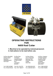
1
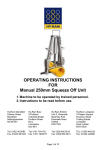
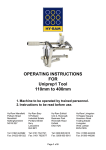
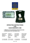
OPERATING INSTRUCTIONS
FOR
HY-RAM MINI 13
(Lightweight 40v/80v welding unit)
1. Machine to be operated by trained personnel.
2. Instructions to be read before use.
Hy-Ram Mansfield
Pelham Street
Mansfield
Nottinghamshire
NG18 2EY
Hy-Ram Bury
9 Portland
Industrial Estate
Portland Street
Bury
Lancashire
BL9 6EY
Hy-Ram Enfield
Unit 2, Riverwalk
Business Park
Riverwalk Road
Enfield
EN3 7QN
Hy-Ram Livingston
18 Napier Square
Houstoun Road
Trading Estate
Livingston
West Lothian
EH54 5DG
Tel: 01623 422982
Fax: 01623 661022
Tel: 0161 7641721
Fax: 0161 7620577
Tel: 0208 805 8010
Fax: 0208 805 6010
TEL: 01506 440233
Fax: 01506 440266
Page 1 of 10
Safety Notes:
• RISK OF EXPLOSION! This welding unit must not be used in a gaseous
atmosphere.
• RISK OF ELECTRIC SHOCK! Do not open. No user serviceable parts inside.
• Before using, always visually inspect the unit to see that the cables and
connectors are not worn or damaged. Replace the damaged part before
welding.
• Switch off and remove the plug from the mains before adjusting, cleaning, or
if the cables are entangled and before leaving the equipment unattended for
any period.
• To avoid damaging the unit, do not interrupt the supply voltage or disconnect
the welding cable, while the unit is welding a fitting.
• Do not lift or pull the equipment by its cables.
• Do not disconnect the welding cables by pulling on them, always pull off the
connectors from the fitting.
• Do not start a weld without the pipe correctly inserted into the fitting.
• Do not touch the fitting while welding.
• Do not weld in the rain or leave the equipment outdoors whilst it is raining.
• Weld only in daylight or in good artificial light.
• The operator is responsible for accidents or hazards occurring to other
people or their property while using this equipment. Keep the work area safe!
• Keep bystanders a safe distance away from the machine while welding.
• Never allow people unfamiliar with these instructions to use the welding unit.
Intended Use:
This equipment is intended to weld constant voltage electrofusion fittings suitable
for low, medium and high pressure pipe work systems. It can weld both 39,5 volt
and 79 volt fittings.
The equipment has been approved by Radius Systems for
use with Easigrip fittings.
Page 2 of 10
This welding unit complies with the UK Transco standard T/SP/ECE/1 2005
‘Specification for Electrofusion Control Boxes’, and is suitable for use on all UK gas
distribution networks.
This welding unit complies with the UK Water Industry Specification WIS 04-32-08
‘Specifications for the fusion jointing of polyethylene pressure pipeline systems
using PE80 and PE100 materials’, and is suitable for use on all UK water
distribution networks.
This welding unit has been designed to comply with the International Organization
for Standardization standard ISO12176-2:2000 "Plastic pipes and fittings,
equipment for fusion jointing polyethylene systems , part 2, electrofusion".
Electrical Safety:
WARNING! Switch off and remove the plug from the mains before adjusting,
cleaning or if the cable is cut, damaged or entangled.
This welding unit is Class 1 and requires an earthed (grounded) connection. An
earth spike must be used with generators. The power source must be capable of
providing 6930 Watts at 110 volts.
In compliance with the Transco specification ECE1, this equipment is fitted with
a 32 amp supply plug and is suitable for welding 40 volt fittings. If the
equipment is required to weld large diameter 80 volt Easigrip fittings, it must be
fitted with a 63 amp supply plug.
Extension cables should only be used if they comply with the H07RNF harmonized
standard. They must be fitted with connectors to the BS EN 60309-2 standard. All
cables must be unwound from the reel to stop inductive heating effects. Only use
one 10m extension cable with a conductor size 4.0mm2.
This equipment is fitted with a Residual Current Device (RCD) with a tripping
current of 30 mA. Always check the RCD every time you use it.
The supply cable must be inspected for signs of damage before each use and the
equipment may only be used if in perfect condition. Damaged cables must be
replaced by an approved service agent.
This equipment is classified as “Portable for use on industrial applications”, and
must undergo a formal electrical safety check (Portable Appliance Test) as per
local regulations.
Using the equipment:
Page 3 of 10
This welding unit takes the ambient temperature into account when calculating the
energy required to weld the fitting. It must therefore be allowed to reach ambient
temperature before use and must be at the same temperature as the fitting to be
welded.
Prepare and clamp the pipe and fittings inline with the manufacturers
recommendations.
Connect the welding cable to the unit and the fitting to be welded. Connect the
supply cable to the correct supply voltage and switch the unit on.
The screen will show a welcome message along with the software version and
date. The owner details are then shown
The main menu is now shown on the display. During operation, except while
welding, pressing the star key on the keypad will jump back to this menu.
Notes:
The operation of the unit can be customised by turning welding modes on and
off, along with some features like the cooling time and data logging. This
manual details all available modes and features. For information on how to
customise the welding unit see the “Set Up” section later on in this manual.
The welding unit is fitted with an alpha-numeric keypad, which is used by the
operator to input data. Down the right hand side there are four Quick-Keys, A B C
D. These act as quick shortcut keys, their function being prompted on the screen.
When entering data, letters and numbers can be selected by repeatedly pressing
the same key, e.g. A B C 2 A B C 2 . After a short pause the cursor will move to the
next position. Special characters and spaces can be selected by pressing the 1 or
0 keys. (This is the same method used for text with mobile cell phones.) Pressing
the B Quick-Key will step Back one position. Pressing the C Quick-Key will Clear
the input field.
The unit can record information about the weld, along with the date and time, and
additional operator entered information.
It is possible to enter three pieces of information to identify the weld. The first is the
Operator’s Name, the second is the Location where the weld is being done, and
the third is an Information field for more details.
The display will show all three pieces of information:
Page 4 of 10
Pressing the B Quick-key will select the ‘Operator Name’ and allow changes to be
made. Enter the required information and press the A Quick-key to accept it.
Pressing the C Quick-key will select the ‘Location’ and allow changes to be made.
Enter the required information and press the A Quick-key to accept it.
Pressing the D Quick-key will select the ‘Information Field’ and allow changes to be
made. Enter the required information and press the A Quick-key to accept it.
When all the information has been entered, press the A Quick-key to accept it.
This information will be saved when the weld has been completed, and will be
prompted the next time a new weld is carried out.
The display will also ask if the pipe/fitting has been scraped and clamped. Select
yes or no using the Quick-Keys. This information will be saved on the data log
memory.
The unit can save 2048 welds in memory. When the memory is full, it will be
overwritten from the beginning in blocks of 24 welds. This will allow the last 2000
welds to be held in memory.
An optional “lifetime weld memory” feature is available. This uses an SD memory
card fitted internally that records every weld carried out by the unit. This is
designed as a backup device and can only be downloaded by an approved service
agent.
Manual Welding 40 volt (Optional)
This mode of operation is designed to weld all 39,5 volt fittings in manual mode,
using the black welding cable.
It is the operator’s responsibility to make sure the correct fitting is being
welded.
From the main menu:
Press the A Quick-Key to select 40 volt manual welding.
The screen will prompt the operator to confirm that 40 volt welding has been
selected. Press the A key to accept. The screen will move on.
Press the A Quick-Key to weld with data logging OFF.
Press the B Quick-Key to weld with data logging ON.
The display will ask for the correct welding cable to be connected to the fitting. The
equipment will check and not allow an 80v cable to be used. When this has been
Page 5 of 10
done it will show the data logging options (if selected). Enter the information as
required.
The display will now prompt for the welding time to be entered. Press the C Quickkey to select the welding time. Enter this from the numbered keypad, e.g. 100. This
can be between 1 second and 3600 seconds. Press the A Quick-key to accept the
new time.
When the correct time has been selected, press the A Quick-key to accept them.
The display will now ask for the START button to be pressed. Press Start to begin
welding.
During the weld, the display will show the set welding time, the remaining welding
time, the set welding voltage and the welding power generated in the fitting. The
unit will also monitor the welding to make sure it does not go out of limits. Any
faults that are detected will terminate the welding and cause an error message to
be displayed. These are listed later on in this manual.
(Optional cooling time) At the end of the weld the cooling time will be shown. This
counts upwards from zero and will continue until stopped by the operator. This is
shown as an aid to the operator to allow them to know how long it was since the
weld finished. Press any key to continue.
The display will ask for the welding cable to be disconnected from the fitting. Doing
this will reset the unit back to the welding menu.
Manual Welding 80 volt (Optional)
This mode of operation is designed to weld all 79 volt fittings in manual mode,
using the blue welding cable.
It is the operator’s responsibility to make sure the correct fitting is being
welded. A 63 amp supply plug MUST be fitted for this mode.
From the main menu:
Press the B Quick-Key to select 80 volt manual welding.
The screen will prompt the operator to confirm that 80 volt welding has been
selected. Press the A key to accept. The screen will move on.
Press the A Quick-Key to weld with data logging OFF.
Press the B Quick-Key to weld with data logging ON.
The display will ask for the correct welding cable to be connected to the fitting. The
equipment will check and not allow a 40v cable to be used. When this has been
done it will show the data logging options (if selected). Enter the information as
required.
Page 6 of 10
The display will now prompt for the welding time to be entered. Press the C Quickkey to select the welding time. Enter this from the numbered keypad, e.g. 100. This
can be between 1 second and 3600 seconds. Press the A Quick-key to accept the
new time.
When the correct time has been selected, press the A Quick-key to accept them.
The display will now ask for the START button to be pressed. Press Start to begin
welding.
During the weld, the display will show the set welding time, the remaining welding
time, the set welding voltage and the welding power generated in the fitting. The
unit will also monitor the welding to make sure it does not go out of limits. Any
faults that are detected will terminate the welding and cause an error message to
be displayed. These are listed later on in this manual.
(Optional cooling time) At the end of the weld the cooling time will be shown. This
counts upwards from zero and will continue until stopped by the operator. This is
shown as an aid to the operator to allow them to know how long it was since the
weld finished. Press any key to continue.
The display will ask for the welding cable to be disconnected from the fitting. Doing
this will reset the unit back to the welding menu.
Easigrip Welding (Optional)
This mode of operation is designed to weld Easigrip 79 volt fittings, manufactured
and sold by Radius Systems. It is the operator’s responsibility to make sure the
correct fitting is being welded.
A 63 amp supply plug must be fitted.
Ensure the pipes to be joined can be aligned and are
supported so that the assembled pipes and fitting can
be jointed unstressed.
Use rerounding clamps on large diameter pipes 450mm
and above. These should remain on the pipe ends for
10 minutes.
Reposition the first clamp and use the PET to score
through the skin. Peel the skin off the pipe when ready
to position the electrofusion coupler.
Page 7 of 10
Slide the coupler into position and check the socket fit.
The socket should be positioned up to the centre stops.
Mark the outside of the pipe at the edge of the coupler.
Reposition the second clamp and score through the
skin on the second pipe section. Peel off the skin and
position the coupler.
Mark the insertion depth on the second pipe and using
the appropriate lifting aids, slide the second pipe into
the coupler up to the correct insertion depth.
Position the tie bars through the locking cams to
immobilise the pipes and fitting.
The fitting can now be welded using the following
alignment clamps procedure. The Blue welding cable
must be used. When complete, allow to fully cool
before removing the from the main menu:
Press the C Quick-Key to select 80 volt Easigrip welding.
The screen will prompt the operator to confirm that 80 volt welding has been
selected. Press the A key to accept. The screen will move on.
Press the A Quick-Key to weld with data logging OFF.
Press the B Quick-Key to weld with data logging ON.
The display will now prompt for the three welding times to be entered:
To enter the Pre-heat time, press the B key then enter the time using the numeric
keypad. Press the A key to accept.
To enter the Soak time, press the C key then enter the time using the numeric
keypad. Press the A key to accept.
To enter the Weld time, press the D key then enter the time using the numeric
keypad. Press the A key to accept.
When the correct times have been selected, press the A Quick-key to accept them.
The display will now ask for the START button to be pressed. Press Start to begin
welding.
During the weld, the display will show the set welding time and the remaining
welding time for each section of the weld. The unit will also monitor the welding to
Page 8 of 10
make sure it does not go out of limits. Any faults that are detected will terminate the
welding and cause an error message to be displayed. These are listed later on in
this manual.
(Optional cooling time) At the end of the weld the cooling time will be shown. This
counts upwards from zero and will continue until stopped by the operator. This is
shown as an aid to the operator to allow them to know how long it was since the
weld finished. Press any key to continue.
The display will ask for the welding cable to be disconnected from the fitting. Doing
this will reset the unit back to the welding menu.
Extreme Low Temperature Operation (Optional)
The welding unit has an extended temperature range option, which allows it to
work down to -40oC. This unit has special supply and welding cables that remain
flexible at extremely low temperatures. It also has an internal case heater to warm
the electronics to an acceptable working temperature.
When the temperature inside the unit is below -15oC, the following operation will
apply:
Plug the welding unit into the correct supply voltage and switch it on.
The internal case heater will switch on and an indicator light will show on the lid
next to the display.
When the internal temperature warms to the correct level, the case heater will
switch off, the indicator light will switch off and the electronics will switch on.
The operation of the unit is now as previously described.
Extended temperature range facility is a factory-fitted option and must be
requested when ordering the product from you supplier.
Downloading the Weld Memory
The data log memory is downloaded by using an ‘industry standard’ USB flash
memory device. The data can be encrypted for protection, to stop unauthorised
alteration of the information.
A data download manager is available free of charge and is supplied on the USB
memory device with the welding unit. This allows the encrypted data to be read,
filtered, printed and saved. It also allows the data to be saved as an encrypted file
or as a Microsoft Excel spreadsheet.
Plug the USB flash memory drive into the USB connector on the side of the
welding unit.
From the main menu:
Press the D Quick-Key to select options.
Page 9 of 10
Press the A Quick-Key to select download data.
Confirm that you want to download the data. The display will show that it is
“Enumerating the device”. While this is showing, the unit is initialising the memory
drive. The data will now be downloaded.
The display will ask if you want to reset the data log memory. Select yes or no then
disconnect the memory drive when prompted to do so.
The data can be download as either an encrypted PFD file, or as a plain text XLS
file. To change the setting please contact your approved service centre.
Hy-Ram Engineering Co. Ltd
Tel : + 44 1623 422 982 Fax : + 44 1623 661 022
Page 10 of 10