1
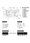
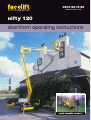
0800 52 15 95
www.facelift.co.uk
nifty 120
shortform operating instructions
road towable access
This book is designed as a guide to enable you to start work quickly and safely. It is not intended
to replace the full manufacturer’s operating instructions (a copy of which should be with your
machine) which should be read and understood by anyone operating the machine.
SAFETY TIPS
ALWAYS
NEVER
• Inspect your machine before use.
• Use an unsafe machine.
• Check all operations including ground controls.
• Use an access platform to hoist loads like a crane.
• Check ground conditions.
• Overload cage/platform.
• Check clearance from overhead obstructions (power
cables, building projections etc).
• Operate in strong winds (Check manufacturer’s
recommendation).
• Plan your task/job.
• Rest the cage on a structure or object to gain
extra support.
• Use sole boards under your outriggers at all times
regardless of ground conditions.
• Stabilise and level machine before use.
• Wear a safety harness connected to a suitable
anchorage point inside the platform.
• Operate all controls smoothly.
• Warn other people that you are there by means of
flashing lights, sign and cones.
• MAKE SAFETY YOUR No.1 PRIORITY.
• Attach your safety harness to a structure outside of
the platform.
• Throw or drop anything from the platform.
• Use boxes, ladders or stand on handrails to gain additional
height, if you can’t reach, you need a bigger machine.
• Let an untrained person operate the access platform.
• Take unnecessary risks (hospitals and graveyards are
full of dead heroes!)
In the unlikely event that your machine develops a fault
please contact the Facelift Tech Team on 01444 881100
CONTENTS
Daily Safety Check List ..........................................1
Starting The Engine From The Platform ................3
Setting Up Procedures ..........................................1
Power System Changeover ..................................4
Ground Control Operation ....................................2
Boom Controls ......................................................4
Platform Control Operation ....................................2
Emergency Controls ..............................................5
Platform Pushbutton Controls Station....................3
Notes ....................................................................5
DAILY SAFETY CHECK LIST
Before use each day and at the beginning of each shift the aerial
platform shall be given a visual inspection and functional test
including, but not limited to, the following:
4)
If the load bearing capacity of the ground is in any doubt
the machine must not be used.
5)
APPLY HANDBRAKE; and/or chock wheels and cordon
off area using appropriate cones, barriers and flags.
6)
Release boom travelling clamp. (if applicable)
7)
Check all red emergency stops are not engaged i.e. fully out.
8)
Hydraulic outriggers proceed to step 9. Manual outriggers
proceed to step 16.
9)
Ensure selector hand valve adjacent to ground control
station is turned fully down to outrigger position.
1)
Read and fully understand Operating and Safety Manual.
2)
Check safety belts and hard hats.
3)
Check all decals and placards to see if in place and legible.
4)
Check platform is securely fastened to platform support.
5)
Check wheels and tyres (40psi or 65psi (Bi-energy).
6)
Check outriggers (if applicable) for condition, microswitch
operation and security.
10) Ensure key switch selector at ground control station is
turned to ground position, i.e. fully down.
7)
Check batteries for condition, cleanliness, connections and
electrolyte levels.
8)
Check engine oil, fuel and coolant levels (if applicable).
9)
Check installation of all guards, covers and boom clamps.
11) From the outrigger control station depress and hold the
green button to give hydraulic power to the outriggers and
select the appropriate lever. Note: no power will be
available if the booms are not stowed in the boom rest.
12) Using the four outrigger control levers, lower each outrigger
onto a firm level surface and level machine base ensuring
each outrigger foot is taking equal weight with the wheels
clear of the ground. Deploy front two outriggers first to
minimise the risk of damaging the jockey wheel.
10) Check for loose, missing or damaged parts.
11) Check all hydraulic hoses and electrical cables and wiring.
12) Check hydraulic, fuel and air systems for leaks.
13) Do not exceed rated platform capacity 440lbs (200kgs).
14) Check foot pedal for proper operation (if applicable).
13) Check base is level using spirit level adjacent to outrigger
control station.
15) Check all operating emergency controls – Select an area free from
obstructions and hazards. Exercise extreme caution throughout
the checking procedure especially when checking brakes.
14) Change selector valve at ground station to platform, i.e.
fully up.
16) Check operation of emergency hand pump.
19) Check high engine and/or high drive limit switches.
15) The booms can now be operated from the ground control
station by depressing and holding the green power button.
Note: if no power is available check each outrigger is
lowered and each footpad is taking equal weight.
20) Check and refer to operating and safety manual for further
daily/periodic checks and inspections.
MANUAL OUTRIGGER MODELS
17) Check brakes and all lights.
18) Check tilt sensor/alarm horn and beacons (if fitted).
16) Leave ground control key in centre off position until jacks are
deployed. Turning this key to platform position will cause
klaxon to sound, as the outriggers will detect that the jacks are
not in contact with the ground.
SETTING UP PROCEDURES
17) All four outrigger beams must be fully extended and
retaining pins engaged (dropped) and all jack feet screwed
down hard onto a firm level surface.
18) Level base using the two spirit levels mounted on the base.
19) To operate the booms from the ground, turn the key
switch selector at the ground control station to ground,
i.e. fully down. Press and hold green power button and
select appropriate ground control lever. NOTE: if no
power is available check easch retaining pin has engaged
(dropped) and each jack foot is screwed hard down onto
a firm level surface.
FAILURE TO DEPLOY THE OUTRIGGERS CORRECTLY
COULD RESULT IN DEATH OR SERIOUS INJURY.
ALL MODELS
1)
Read and fully comply with all safety precautions and
operating instructions in the Operating and Safety manual
and the warning decals on the machine.
2)
Position Niftylift on firm, level ground. NEVER work with
base across or adjacent to any slope.
20) To operate the booms from the platform turn the key
switch selector at the ground control station to platform,
i.e. fully up. NOTE: if alarm sounds return key to centre
‘off’ position and each jack foot is screwed hard down
onto a firm level surface.
Use the manual jacks to level the base of the machine, if
necessary using suitable load bearing pads to support the
downhill jacks. A slope of up to 12 degrees can be
accommodated in this fashion. Do not elevate the platform
unless the base can be corrected to within 3 degrees of level.
3)
ALL MODELS
21) Always lower booms fully before adjusting, raising,
retracting or moving the outriggers in any way.
Position Niftylift, bearing in mind range of boom movement
so that any overhead obstruction or possible hazards such
as, but not limited to, power cables, telephone lines, drains,
man-hole covers, etc.
22) Never alter, modify or block any of the safety circuits on
the Niftylift.
1
GROUND CONTROL OPERATION
EMERGENCY PROCEDURES
14) Push in red emergency stop to shut down all functions.
15) Operate emergency hand pump and lower on hand
lever controls.
16) To swing booms fit a 1/2 in drive socket to the end of worm
gear and crank round manually.
ALWAYS ALLOW THE ENGINE TO WARM UP
BEFORE OPERATING.
BOOM FUNCTIONS
A)
Push and hold green power button.
ALL MODELS
1)
Ensure all red emergency stops are out.
2)
Turn key switch at ground control station to ground (i.e.
fully down).
3)
Ensure selector hand valve (if applicable) is turned to
platform position (i.e. fully up).
4)
Battery electric models, go to step 10.
P14926/001
1
B)
DIESEL ENGINE OR BI-ENERGY MODELS
5)
Turn duty selector in platform to BATT (battery) or
ENG (engine).
6)
If BATT (battery) is selected go to step 10.
7)
If ENG (Engine) is selected go to step 8). for a COLD
ENGINE or step 9). for a WARM ENGINE.
8)
COLD ENGINE turn the main engine ignition switch (located
beneath the front cover) through ON to GL. This engages the
glow plug pre-heat system. Hold for 3-5 seconds then turn
key fully to ST (start) position and the engine will fire.
9)
WARM ENGINE turn the main engine ignition switch
(located beneath the front cover) through ON to ST (start)
position and the engine will fire.
Turn duty selector in platform to BATT (Battery) or
ENG (Engine).
6)
If BATT (Battery) is selected go to Step 10).
7)
If ENG (Engine) is selected go to Step 8). for a COLD
ENGINE or Step 9). for a WARM ENGINE.
8)
COLD ENGINE turn the engine fuel tap on and engage the
choke lever. Turn the main engine ignition through ON to ST
(Start) and the engine will fire. Return the choke lever to its
normal running position after the engine is started.
9)
WARM ENGINE turn the engine fuel tap on and turn the
main engine ignition through ON to ST (start) position and
the engine will fire.
3
Select lever 1, 2, or 3 for desired boom function.
1 Operates Lower Boom: Up for up
Down for down.
2 Operates Upper Boom: Up for up
Down for down.
3 Operates Swing:
Down for left.
Up for right
ALWAYS ENSURE THE AERIAL PLATFORM IS ON
A FIRM, LEVEL SURFACE AND THE AREA IS FREE
OF ANY OVERHEAD OBSTRUCTIONS.
ENGAGING THE RED EMERGENCY BUTTON WILL SHUT
DOWN THE ENGINE AND THE ELECTRIC CIRCUIT,
PREVENTING OPERATION OF ANY FUNCTION.
PETROL (GASOLINE) ENGINE OR PETROL
(GASOLINE)/ELECTRIC MODELS
5)
2
PLATFORM CONTROL OPERATION
NEVER START THE NIFTYLIFT IF YOU SMELL PETROL
(GASOLINE), LIQUID PROPANE OR DIESEL. THESE
FUELS ARE FLAMMABLE.
ALL MODELS
10) Push and hold green power button.
11) Select function and operate handlevers in full accordance
with manufacturers operating and safety manual.
12) To return control to platform turn key fully clockwise to
up position.
BEFORE OPERATING THE NIFTYLIFT ENSURE THAT
EACH OPERATOR HAS READ AND FULLY UNDERSTOOD
THE OPERATING MANUAL. FAILURE TO DO SO MAY
RESULT IN DEATH OR SERIOUS INJURY.
13) When not in use return machine to stowed position, fully
raise and stow all outriggers, turn key to centre off position,
remove key and chock wheels.
2
PLATFORM PUSHBUTTON
CONTROLS STATION
PLATFORM CONTROLS
ALL MODELS
1)
Ensure all red emergency stops are out.
2)
Turn key switch at ground control station fully up to
platform position.
3)
Ensure selector hand valve (if applicable) is turned to
platform position i.e. fully up.
4)
Battery electric models go to step 10).
(BI-ENERGY MODEL SHOWN)
DIESEL ENGINE OR BI ENERGY MODELS ONLY
5)
Turn duty selector in platform to BATT (Battery) or
ENG (Engine).
6)
If BATT (Battery) is selected go to Step 10).
7)
If ENG (Engine) is selected go to Step 8) for cold engine or
Step 9) for a warm engine.
8)
COLD ENGINE Turn the main engine ignition switch
(located beneath the front cover) through ON to GL, this
engages the glow plug pre-heat system. Hold 3-5
seconds then turn key fully to ST (start) position and the
engine will fire.
9)
BOOM FUNCTIONS
P14926/001
1
2
3
Select lever 1, 2, or 3 for desired function.
WARM ENGINE Turn the main engine ignition switch
(located beneath the front cover) to ON. Push the BLACK
start button located behind the main push button control
station and the engine will fire.
1 Operates Lower Boom:
Up for up
Down for down.
2 Operates Upper Boom:
Up for up
Down for down.
3 Operates Swing:
Up for right
Down for left.
STARTING THE ENGINE
FROM THE PLATFORM
PETROL (GASOLINE) ENGINE OR PETROL
(GASOLINE)/ELECTRIC MODELS ONLY
10) Turn duty selector in platform to BATT (Battery) or
ENG (Engine).
11) If BATT (Battery) is selected go to Step 10).
12) If ENG (Engine) is selected, ensure the fuel tap is turned to
the ON position and then go to Step 8) for cold engine or
Step 9) for a warm engine.
NEVER START THE NIFTYLIFT IF YOU CAN SMELL
PETROL (GASOLINE), LIQUID PROPANE OR DIESEL.
13) COLD ENGINE (From the ground only) turn the engine fuel
tap on and engage the choke lever. Turn the main engine
ignition through ON to ST (Start) and the engine will fire.
Return the choke lever to its normal running position after
the engine is started. WARM ENGINE Ensure the main
engine ignition switch is ON. Push the BLACK start button
located behind the main push button control station and
the engine will fire.
THESE FUELS ARE HIGHLY FLAMMABLE.
****FOR COLD START PROCEDURES SEE PLATFORM
CONTROL OPERATION: STEP 8
A)
Ensure main engine ignition located below front cover is
turned to ON position.
B)
Ensure that all EMERGENCY STOPS are not engaged (i.e.
must be fully out).
ALL MODELS
C)
14) Ensure key switch selector is turned to ON or BATT
(Battery) if applicable.
Ensure the key switch selector located at the ground
control station is turned to platform (i.e. fully up).
D)
15) Depress foot switch or push and hold green power button.
Ensure the duty selector in the platform is in the ENG
(Engine) position.
16) Select function and operate hand levers in full accordance
with manufacturers Operating and Safety Manual.
E)
Push the BLACK start button located behind the main push
button control station and the engine will now fire up.
17) When not in use return booms to stowed position.
Fully raise and stow all outriggers. Turn key switch at
ground control to centre off position, remove key and
chock wheels.
F)
To shut down the engine from the platform simply turn the
duty selector to OFF or BATT (Battery) or in an emergency
depress the RED Emergency stop button.
3
POWER SYSTEM CHANGEOVER
Control 2 Operates upper boom UP for up
DOWN for down
ENGINE TO BATTERY
Control 3 Operates swing
1)
Engage any RED Emergency Stop button to shut down
the engine.
2)
Re-set RED Emergency Stop button.
3)
Turn the duty selector in the platform to BATT (Battery).
UP for right
DOWN for left
BATTERY TO ENGINE
1)
Ensure all RED Emergency Stops are out.
2)
Ensure main engine ignition switch located at the ground is
turned to ON.
3)
Turn the duty selector in the platform to ENG (Engine).
4)
Push the BLACK START button located behind the main push
button control station and the engine will fire.
THIS MACHINE IS NOT ELECTRICALLY INSULATED.
DO NOT WORK WITHIN 3M (10FT) OF
OVERHEAD CABLES EXCEEDING 415 VOLTS.
TOWING
PETROL TO GAS
1)
Locate petrol shut-off valve on carburettor, and turn petrol
to OFF position.
2)
Run engine until all of the Petrol is exhausted, i.e.
engine stops.
3)
Open valve on gas bottle, introducing supply to
the vapouriser.
4)
Turn engine over until it fires, allow vapouriser to achieve
running temperature before using machine. If engine runs
erratically, check that all petrol has been used from bowl.
THE MAXIMUM TOWING SPEED OF A NIFTYLIFT IS
45MPH (72 KMPH) WITH A VEHICLE THAT COMPLIES
WITH ALL ROAD TRAFFIC REGULATIONS. SPEEDING
MAY RESULT IN DEATH OR SERIOUS INJURY.
It is recommended that the maximum towing speed of
45mph (72kmph) be adhered to for the greatest safety. In other
than perfect conditions it is sensible to further reduce your
speed in order to ensure full control over your vehicle and
trailer. The importance of the suitability of your towing vehicle
must be stressed. The manufacturers’ details concerning each
model will give you recommended Gross Vehicle Weights
(GVW) or Gross Train Weights (GTW) neither of which should
be exceeded.
GAS TO PETROL
1)
Turn gas off by shutting valve on the bottle – ensure that it
is fully closed.
2)
Open fuel shut-off valve on engine carburettor, and allow it
to fill with petrol.
3)
Turn engine over until it fires.
POSITION TOWING VEHICLE AND TRAILER ON LEVEL
GROUND BEFORE ATTEMPTING TO COUPLE/DE-COUPLE.
BOOM CONTROLS
Coupling Instructions
DO NOT OPERATE THE NIFTYLIFT WHILST
ELEVATED UNLESS ON A FIRM, LEVEL SURFACE FREE
FROM ANY POSSIBLE OBSTRUCTIONS OR HAZARDS
BOTH AT GROUND LEVEL AND OVERHEAD.
1)
Depress the trigger on the lever mechanism and lift the
handle upwards and forward.
2)
Place the unlocked coupling head onto the towing ball and
apply slight downward pressure. The head will automatically
lock onto the ball.
3)
Ensure that the trigger has returned to its free position
before attempting to tow, and that the coupling head is
securely on the towing ball.
4)
Connect the breakaway cable/chain to the towing vehicle
hitch – not to the tow ball itself.
IF ALARM SOUNDS – DESCEND IMMEDIATELY.
1)
Never exceed the maximum platform capacity of
440lbs (200kgs).
5)
Connect the lighting plug to the vehicle and check the
light functions.
2)
Check below, above and around platform for any obstruction
or hazards before operating any function.
6)
Raise the jockey wheel to its stowed position and secure
for transit.
3)
Depress the green power button or the foot switch located
in the platform floor (if applicable).
De-coupling Instructions
4)
Select handlever controls marked 1, 2, 3.
1)
Apply trailer handbrake and/or chock wheels.
Control 1 Operates lower boom
2)
Lower the jockey wheel to the ground. Disconnect the
breakaway cable/chain and lighting plug.
UP for up
DOWN for down
4
3)
NOTES
Operate the handle by depressing the trigger and manually
lift the coupling head clear of the towing ball or screw down
the telescopic jockey wheel to achieve the same effect.
Handbrake Operation
1)
To operate the trailer parking brakes pull the handbrake
lever upwards and backwards. The spring loaded
mechanism will engage and stay in the operated position
until re-set.
2)
To disengage the parking brakes, firmly grasp the
handbrake lever and pull upwards. Depress the ratchet
release button in the end of the handbrake lever and return
the lever to the horizontal position. Care should be taken
when operating the handbrake lever due to the forces
involved in engaging the ratchet mechanism.
EMERGENCY CONTROLS
GENERAL
CHECKING THE OPERATION OF THE EMERGENCY
CONTROLS EVERY DAY AND/OR BEFORE EACH SHIFT
IS AN ESSENTIAL PART OF THE OPERATORS DUTIES.
The operator and all ground personnel must be
thoroughly familiar with the location and operation of the
EMERGENCY CONTROLS.
IN THE EVENT OF AN
INCAPACITATED OPERATOR.
Turn key switch selector at ground control station to ground (i.e.
fully down). Lower on ground controls as detailed in section
GROUND CONTROL OPERATION.
IN THE EVENT OF MACHINE FAILURE.
Lower platform using handlever controls in platform or at ground
control station and simultaneously operate the handpump. This
operation can be completed from either the cage or base controls.
TO ROTATE PLATFORM IN AN EMERGENCY.
Fit 1/2 inch drive socket on to end of swing worm gear and
crank round manually.
5
0800 52 15 95
www.facelift.co.uk
operator training centre
When hiring access equipment we
strongly recommend taking
advantage of one of our one day
operator training courses
As Facelift is an accredited
IPAF (Independent Powered
Access Federation) training
centre you can be sure that
your staff will be trained to
a high standard and
receive an internationally
recognised qualification.
Courses can take place on your own premises or at one of our training
centres, situated in Hickstead, Iver, Southampton and Liverpool.
We can train your personnel on any of the following equipment:
(SL) Scissor Lift
(SPB) Self Propelled Boom
(VMP26) Truck/Van mounted to 26m
(VMP200) Truck mounted over 26m
(VPP) Vertical Personnel Platform
(TP) Trailer/Push around
The one day course* covers site safety, practical demonstration, sole
usage and site risks and includes a theory test.
*(two day course for VMP200)
Successful candidates are issued with the IPAF PAL card, widely
accepted by both the CITB and Health And Safety Executive.
For further information or to arrange a training course call us today on:
0800 0 72 55 72