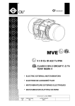
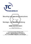
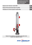
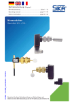
1
Operating instructions
Betriebsanleitung
Level sensor model FFG
GB
Niveau-Messwertgeber Typ FFG
D
Level sensor, magnetostrictive measuring principle,
model FFG; flange connection
D
Operating instructions level sensor
Model FFG
Betriebsanleitung Niveau-Messwertgeber
Typ FFG
2
Page
3-22
Seite
23-42
WIKA operating instructions level sensor model FFG
13445627.01 12/2010 GB/D/F
GB
Contents
Contents
GB
1.
Safety information
4
3.
Area of application
9
2.
4.
5.
6.
7.
8.
9.
Description of functions and design
Assembly
Electrical connection
Maintenance
Trouble shooting
Technical specifications
Float selection
6
9
13
19
19
20
22
WARNING!
Instructions on correct installation and proper operation.
Failing to comply with these instructions can lead to
malfunction of or damage.
13445627.01 12/2010 GB/D/F
DANGER!
Instructions which must be complied with to avoid injury or
property damage or loss of the type permit.
DANGER!
Instructions for proper electrical installation.
Information
Facts and information concerning proper operation.
WIKA operating instructions level sensor model FFG
3
1. Safety information
1. Safety information
GB
Please read these instructions carefully before installing and
commissioning the model FFG level sensor system. These
instructions are directed to trained personnel implementing the assembly, installation and set-up of the system.
The level sensor serves for indicating the level of liquids in
containers. Use it for no purpose other than this! No liability
will be assumed by Manufacturer for damage resulting from
use other than specified! The level sensor has been designed, manufactured and tested in accordance with the state
of art and the accepted safety regulations. Notwithstanding
this, certain risks might be involved.
The following safety instructions should, therefore, be observed:
Do not modify, supplement or change the level sensor system unless
with Manufacturer’s express approval. Unauthorized changes or
non-permitted use will result in immediate loss of warranty or liability
claims.
The installation, operation and maintenance must be performed by
expert and authorized personnel only. The required expertise must be
obtained by regular training.
The current and voltage values specified for an intrinsically safe operation must be complied with.
4
WIKA operating instructions level sensor model FFG
13445627.01 12/2010 GB/D/F
It is imperative for operators, installers and servicers to comply with all
applicable safety regulations. This provision shall extend to all local
safety and accident preventing regulations not expressly referred to
herein.
1. Safety information
Prior to starting operation please check all devices for their proper
connection, operability and power supply; this shall also apply to
assemblies coupled thereto.
GB
The general operating instructions of all devices as used must be
abided by.
Measures should be taken preventing personal injuries and damage
to property from occurring in case of a defective condition of the level
sensor system.
The level sensor system must not be operated in the direct vicinity of
strong electromagnetic fields (minimum distance: 1 m).
The level sensor system must not be exposed to heavy mechanical
strain.
13445627.01 12/2010 GB/D/F
The maximum power and voltage values for the intrinsically safe
operation as specified in the assembling and operating instructions
should be adhered to.
The safe operation of the system with a view to
pressure and temperature of the materials as employed shall be Operator’s responsibility.
As even in case of failure, the guide tube does not exhibit a
source of ignition there are no objections, in terms of safety,
to use the sensor (float and guide tube) as an operating
unit of the 1/2 category with containers for combustible
fluids (except for carbon disulphide and silicon-organic
compounds) under varying atmospheric conditions at
excess pressures of up to 25 bar and temperatures of
between -60 ... +250 °C.
WIKA operating instructions level sensor model FFG
5
1. Safety information / 2. Description of functions ...
DANGER!
Work in containers involves the danger of intoxication and
suffocation. No work is allowed to be carried out unless by
taking suitable personal protective measures (e.g. respiratory protection apparatus, protective outfit etc.).
GB
Danger of explosion
Inside the container, there is danger of an explosive atmosphere. Corresponding measures for preventing sparking
should be taken. No work is allowed in this area unless by
technically skilled staff in accordance with applicable safety
regulations.
2. Description of functions and design
The design of the level sensor system is shown in figure 1 in the form
of embodiment furnished with a screwed-in element. Provided in the
probe head (1) is the area of connection and adjustment protected by
lid (2). The electrical connection is via an M16x1.5 cable gland (3) at
the top of the probe head while the earth connection (4) is at the bottom
of the probe head. Seated on the probe tube (5) for vertically adjustable
assembling purposes, within the container, is a compression fitting (6)
(G 1/2, W 27) or a flange (not shown). The float (7) serves for continuously gauging the product level or interface layer, and is held on the
probe tube by a guiding or locking ring (8) etc.
6
WIKA operating instructions level sensor model FFG
13445627.01 12/2010 GB/D/F
The WIKA model FFG level sensor acts as a measured value transmitter
for high-accuracy, continuous level measurement of liquids and is
based on identifying the position of a magnetic float following the
magnetostrictive measuring principle.
2. Description of functions and design
GB
Fig. 1: Level sensor system model FFG
13445627.01 12/2010 GB/D/F
The level sensor shown in figure 2 serves for the continuous
measurement of fluids. To transmit the liquid level value to the sensor, a
float is sliding on the sensor tube. The operating principle of the sensor
is based on the magnetostriction effect. The float contains a magnet
while a wire made of magnetostrictive material is installed under tension
inside the sensor tube. The magnetic field of the float is twisting the
wire. A second, temporary magnetic field is generated along the wire by
a current pulse within the wire. The superposition of the two magnetic
fields will release a mechanical wave on the wire.
At the end of the wire within the sensor head, the mechanical wave is
converted by a piezo-ceramic transducer into an electrical signal. The
starting point of the mechanical wave and, hence, the float position is
then determined by measuring the transit time.
The results of such measurements are feasibility-tested by a microcontroller located in the sensor head and are then converted into a current
value by a digital analog transformer. The sensor is provided with a
2-wire connection so that the current consumption indicates the position
of the float at the same time. The current values are restricted to a range
of between 3.5 ... 23 mA.
WIKA operating instructions level sensor model FFG
7
2. Description of functions and design
GB
Fig. 2: Functional principle
Removal of the transportation packing and
transportation safety bolts
Carefully remove the level sensor from the transportation packing.
Please observe the warning on the shipment packing and remove all
transportation safety bolts, prior to discharging the level sensor system.
Never remove the level sensor system from the packing by applying
force to the guide tube!
Prior to assembly the safety bands are to be removed from the floats.
Make sure that all packing elements have been removed and that the
floats are free to move on the guide tube.
8
WIKA operating instructions level sensor model FFG
13445627.01 12/2010 GB/D/F
Transport and storage
Transport and storage for level sensors are only allowed in designed
packaging.
3. Area of application / 4. Assembly
3. Area of application
The level sensor system is available for employment in varying container GB
heights of between 200 and 6000 mm. Flange-model or screw-model
designs are available allowing a stepless positioning within the container, depending on the design thereof.
Probe tube and float can be installed up to the screw element or flange
in areas exposed to danger of explosion, in which electric units of the
category 1/2 (zone 0) are required. In respect of the bypass model, the
complete system is allowed to be installed in areas exposed to danger
of explosion that require electric unit of category 2 (zone 1). The sensor
head of the level sensor can be operated at ambient temperatures
of between -40 ... +85 °C, while the sensor tube is operable within a
temperature range of between -25 ... +250 °C. The permitted process
temperatures in case of employment in zones subject to danger of
explosion that require operating units of categories 1/2 or 2, are set out
in the tables.
The technical specifications set out in these operating
instructions should be observed.
13445627.01 12/2010 GB/D/F
4. Assembly
Assembly and servicing in areas exposed to danger of
explosion shall be in accordance with the provisions
stipulated by ElexV and the Act on Appliance Safety
and shall be in accordance with all applicable rules
of technology and the present operating instructions.
Moreover, please also observe all local safety and
accident preventing regulations that have not been
expressly mentioned in these operating instructions.
Make sure, during assembly that the probe tube is not
bent and that the float is not exposed to shock.
The level sensor having Ex-approval must be so
mounted that the probe head is not located in the
Ex-zone 0.
WIKA operating instructions level sensor model FFG
9
4. Assembly
The level sensor systems, depending on the design thereof, will be
mounted into the container by means of a flange or a screw-in thread.
Make sure, prior to assembly, that the assembly port provided on
GB
the container and the attachment means of the level sensor system
conform in size and dimension. Depending on the design of the level
sensor system, assembly thereof into the container must be externally.
Assembly must be in the vertical position. To insure a safe function,
the angle of assembly is allowed to differ from the vertical by 30° max.
The guide tube of the level sensor is to be externally introduced through
the assembly port of the container. Attachment thereof is by tightening
the screw-in thread in respect of threaded plugs; by bolting the cap nut
in respect of dairy pipe fittings; screwing in respect of flange-model
designs or closing of the locking rings (articulated clamp) in triclampmodel clamp connections.
■■ Level sensors having screw-in threads are to be screwed
across the entire thread length.
■■ Level sensor systems having dairy pipe fittings are
furnished, ex factory, with suitable cap nuts.
■■ Level sensor systems of flange-model design are to be
fixed by suitable screws, washers and nuts.
■■ Level sensor systems having clamp connections of the
triclamp model are to be secured by means of suitable
locking rings (articulated clamp).
Suitable sealants should be used. Please make sure that the sealing
material is resistant to the fluid and its vapours and to the anticipated
temperatures and pressures.
In designs having floats mounted thereon the diameters of which
exceed the core diameter of the mounting port the floats should be
removed from the guide tube prior to assembly thereof.
10
WIKA operating instructions level sensor model FFG
13445627.01 12/2010 GB/D/F
Please observe the torque value of the screws!
4. Assembly
Fig. 3: Level sensor system with mounting thread
13445627.01 12/2010 GB/D/F
GB
1
Terminal box
2
Cable gland
3
Mounting thread
4
Gasket
5
Guide tube
6
Float
7
PTFE washer
8
Set collar or tension clamp
Procedure:
To mark upper side of floats (e.g. by "top")
To mark position of locating rings
To remove locating rings and drop protection rings
To lift floats
To assemble the level sensor
To mount floats, locating rings and drop protection rings from inside
of container. Please observe markings!
■■
■■
■■
■■
■■
■■
The drop protection rings serve to avoid the formation of
ignition sparks in the event of an impact of the float on the
locating ring. No operation is permitted without the use of
drop protection rings.
WIKA operating instructions level sensor model FFG
11
4. Montage
When using a float made of titanium in areas exposed to
danger of explosion of category 1/2, please make sure,
during installation and operation, that the said float will
generate no sparks caused by friction or shock.
GB
Maximum lengths of guide tubes
Depending on the length and design of the guide tube, the
level sensor must be fixed to the container bottom
(see table).
Guide tube
Max. guide tube length L
12 x 1 mm
16 x 1 mm
17.2 x 1.6 mm
18 x 1.5 mm
L...
12
660
1270
2100
3000
Version B
3500
6000
6000
6000
Version B: Fixed to the tank ceiling
and floor
L...
WIKA operating instructions level sensor model FFG
13445627.01 12/2010 GB/D/F
Version A: Fixed to the tank ceiling
Version A
5. Electrical connection
5. Electrical connection
The level sensor in areas exposed to danger of explosion
GB
are allowed to be connected to buffer amplifiers only if these
are certificated by a generally accepted test institute, and
if the electric specifications thereof are compliant with the
following conditions:
Ui
Ii
Pi
= ≤ 30 V
= ≤ 0.2 A
= ≤1W
Level sensor model FFG
(Standard and pharmaceutical design)
EEx ia
The electric specifications (see product label) and the additional provisions for installing intrinsically safe circuits should be abided by. No work
is allowed to be carried out unless by trained experts.
The electric connection of the level sensor is via built-in clamps. The
given connecting pattern is conveyed by the connection diagram within
the interior of the terminal box, or by the mounting and operating instructions.
13445627.01 12/2010 GB/D/F
Selection of connection cable
Wiring requires a 2-core cable to be connected in the
probe head of the sensor. The cable cross-section must be
selected so that the supply voltage on the level sensor is no
less than 10 V in the borderline case of maximum current
consumption (21.5 mA) in a given cable length L.
A copper cable with a cable cross-section of 1 mm² and a
length of 100 m (100 m forward and 100 m return line) has a
resistance of 3.4 Ω (R = 0.034 Ω x L(m)/F(mm²).
WIKA operating instructions level sensor model FFG
13
5. Electrical connection
If a supplier provides, for example, 13 V at 21.5 mA, the sum
of resistors contained in the supply line is not allowed to be
in excess of (13 V – 10 V) / 0.0215 A = 139 Ω. If the cable is
of a cross-section of 0.5 mm² and if no burden is contained
in the line, the feeder line is not allowed to have a length
greater than L = 139 (Ω) x 0.5 (mm²)/0.034 m = 2050 m.
GB
Note the given connecting pattern
The connection should be carried out with light-blue-marked cable. The
diameter of the connecting cable must be within the clamping range
of the cable gland (5-10 mm). Using other cable diameters involves the
danger of moisture ingress.
The use of individual strands is not permitted!
Cable capacity and inductivity
When determining the required cable length, the highest
permitted inductivities and capacities of the connected
intrinsically safe control unit should be observed. These
values are not allowed to be exceeded.
Connecting the cable
Wiring must be in a voltage-free condition. Compliance
with all special VDE regulations and local provisions of
installation is imperative.
Unscrew lid (1) of probe head with open-end wrench
Loosen sleeve nut (2) of cable bolting
Insert dual-core cable(4) through sleeve nut and re-tighten the same
Connect dual-core cable (4) to screw terminals in probe head,
marked by (+) and (-)
■■ Re-screw lid (1) on probe head
14
WIKA operating instructions level sensor model FFG
13445627.01 12/2010 GB/D/F
■■
■■
■■
■■
5. Electrical connection
GB
Fig. 4: Electrical connection of the level sensor
Observe the general prescriptions of installation!
The connections on the separating amplifier are marked
accordingly. During connection of the poles, there will be no
current flow.
Potential balance and PE connection
Grounding or potential balance can be via the earth terminal at the bottom side of the probe head.
13445627.01 12/2010 GB/D/F
Protect the probe head against the ingress of water!
Safe sealing of the cable inlet is safeguarded from a
5 mm outer diameter of the cable.
Tighten cable glands. Lock lid of probe head.
Wiring of the level sensor for supplying purposes (in Ex, preferably
blue cable) is by a dual-core cable. The cable cross-section is to be
selected so that the supply voltage to the sensor is no less than 10 V in
the borderline case of maximum current consumption (21.5 mA) with a
given cable length L.
WIKA operating instructions level sensor model FFG
15
5. Electrical connection
A copper cable having a length of 100 m (100 m forward and 100 m
return line) has a resistance of 3.4 Ω in a cable cross-section of 1 mm².
(R = 0.034 Ω x L(m)/F(mm²). If a supplier generates, for example, 13 V
GB
at 21.5 mA, the resistivity R is allowed to be 3 V/0.0215 A = 139 Ω. If the
cable is of a cross-section of 0.5 mm² , the feeder line is allowed to have
a length L = R(Ω) x F(mm²)/0.034 m = 2044 m.
Connecting pattern in an area exposed to danger of explosion
Model FFG (Ex-design
Separating amplifier
Fig. 5: Connecting diagram of the Ex-design
Power supply
Minimum voltage: Umin = 10 V + 0.0215 A x ∑R
∑R = Sum of all cable resistancess including feeder line and burden
Adjusting measures
For further details of adjusting the range of measurement reference
(see Fig. 6):
■■ Unscrew lid (1) of probe head with open-end wrench
■■ Keep 4 mA-key (2) pressed for no less than 3 seconds
16
WIKA operating instructions level sensor model FFG
13445627.01 12/2010 GB/D/F
Measuring range span
Two keys and one illuminated diode (LED) in the connecting area of the
probe head serve for adjusting the 4 mA- and 20 mA-points. The level
sensor system is adjusted, ex factory, to the maximum range from 4 mA
on the probe base to 20 mA at the probe head. The range of measurement for adaptation to the given container can be individually adjusted;
however, the distance must be no less than 5 mm. Otherwise the indication direction of the sensor is automatically reversed.
5. Electrical connection
The level sensor system now is in the adjusting mode with the green
LED (4) "Cal/Err" flashing. The current consumption of the level sensor
is 12 mA. Without pressing the key again, the level sensor remains in the
GB
adjusting mode for 20 seconds before changing back to the measuring
mode without modifying the adjustment.
To fix the 4 mA point within this period
■■ move the float to the desired position,
■■ and press down key "4 mA" (2) for a short period of time
(0.1 ... 2 seconds)
13445627.01 12/2010 GB/D/F
The LED display will disappear for 5 seconds, with the current consumption being 4 mA, and thereafter again 12 mA. The level sensor will
remain in the adjusting mode for another 15 seconds before changing
back to the gauging mode.
Fig. 6: Adjustment
To fix the 20 mA point within this period
■■ advance the float to the desired position,
■■ and press down key "20 mA" (3) for a short period of time
(0.1 ... 2 seconds)
WIKA operating instructions level sensor model FFG
17
5. Electrical connection
The LED display will disappear for 5 seconds, with the current consumption of the level sensor being 20 mA, and thereafter again 12 mA. The
level sensor will remain in the adjusting mode for another 15 seconds
GB
before changing back to the gauging mode.
The new adjustment will not be adopted until it automatically changes from the adjusting mode into the measuring
mode (with LED disappearing). For this reason, the level
sensor should not be cut off from the current supply before.
For adjusting the current consumption in the error mode
(see Fig. 5), proceed as follows
■■ unscrew lid (1) of probe head with open-end wrench hold both "4 mA"
(2) and "20 mA" keys (3) simultaneously in pressed for a period of
time of no less than 3 seconds. The green LED (4) "Cal/Err" is flashing
fast, with the current consumption being 16 mA. LED, after 5 seconds,
will cease to flash, displaying, for 2.5 seconds, the set error current
consumption. Once the LED is permanently illuminated, I error =
21.5 mA; once it extinguishes I error = 3.6 mA. With the key not being
pressed down again, the level sensor will remain in the error mode
for another 2.5 seconds before changing back into the gauging mode
without modifying the adjustment. For setting a current consumption of
3.6 mA during the 10-second dwelling time in the error mode
■■ briefly press down the key "4 mA" key (2) (for 0.1 ... 2 seconds). For
adjusting a current consumption of 21.5 mA during the 10-second
dwelling time in the error mode
■■ briefly press down the "20 mA" key (3) (for 0.1 ... 2 seconds).
The new adjustment will not be adopted by the level sensor
until it automatically changes from the adjusting mode to the
gauging mode (with LED disappearing). The level sensor
should, therefore, not be cut off from the power supply before.
18
WIKA operating instructions level sensor model FFG
13445627.01 12/2010 GB/D/F
Current Consumption in the error mode
If the level sensor is due to a failure unable to determine a proper float
position, i.e. a correct filling level, it will change to an error mode after a
short period of time. The current consumption in the error mode has been
adjusted, ex factory, to 21.5 mA although it can be switched to 3.6 mA,
also.
6. Maintenance / 7. Trouble shooting
6. Maintenance
The level transmitters operate free of maintenance and wear when used
GB
properly.
However, within the scope of routine inspections they should undergo
visual checks and be part of the container pressure test.
7. Trouble shooting
In the following table the most frequent failure causes and the required
corrective measures are listed.
Trouble
Cause
Measure of correction
No or
undefined
function
Incorrect
0 ... 100 %
values
13445627.01 12/2010 GB/D/F
Cannot be
attached to the
proper point
within
the container
Incorrect terminal positioning
Insulation secured under
terminals
Locating rings displaced or
incorrectly mounted after
removal from the guide tube
Float wrongly mounted
Incorrect specifications in
order
Waveguide in defective condition caused by mechanical
interference
Incorrect setting
Thread size or flange size
of WFFG-T...EX sensor and
container not conforming
Thread of attachment sleeve
on container in defective
condition
Screw-in thread on level sensor in defective condition
Compare with connecting
diagram
Check terminal points
Check position of locating
ring
Turn float around
Contact factory
Return to factory
Re-adjust or contact factory
Re-design the container
Re-design of level sensor
in factory
Re-work thread or replace
mounting socket
Return to factory
Please give us a call in case of any difficulties. We will do everything we
can to provide you with the required advice and help.
WIKA operating instructions level sensor model FFG
19
8. Technical specifications
8. Technical specifications
Type of protection, explosion and temperature class
II 1/2 G EEx ia IIC T6–T2
II 2 D T95 °C IP 6X
II 1/2 G EEx ia IIB T6–T2
II 2 D T95 °C IP 6X
(pharmaceutical design)
Equipment group:
Equipment category:
Type of protection:
Explosive sub-group:
Temperature class:
II
1G (float and guide tube)
2G / 2D (connecting case)
EEx ia
IIC or IIB (drop protection PTFE)
T2, T3, T4, T5, T6
Summary of electrical specifications of authorized design
variants
Power supply:
Voltage
Consumption Inductivity
of power
(extern.
effective)
DC 10 ... 30 V max. 700 mW
max. 250 μH
Permissible data of control unit:
Ui
Ii
Pi
Li
≤ 30 V
20
≤ 200 mA
≤1
≥ 250 μH
Capacity
(extern.
effective)
Type of
protection
max. 5 nF
EEx ia
Ci
Type of protection
≥ 5 nF
EEx ia
WIKA operating instructions level sensor model FFG
13445627.01 12/2010 GB/D/F
GB
8. Technical specifications
Temperatures, standard and pharmaceutical design
Tempera- Maximum
Maximum ambient Dust maximum surture class process
face temperature
temperature
temperature (sensor head of
(sensor head of level GB
sensor)
level sensor)
Category 1/2
T6
-60 ... 60 °C
T5
-60 ... 80 °C
T4
-60 ... 100 °C
T3
-60 ... 150 °C
T2
-60 ... 150 °C
Category 2
T6
-60 ... 85 °C
T5
-60 ... 100 °C
T4
-60 ... 135 °C
T3
-60 ... 200 °C
T2
-60 ... 250 °C
-40 ... +40 °C
-40 ... +55 °C
-40 ... +85 °C
-40 ... +85 °C
-40 ... +85 °C
-40 ... +40 °C
-40 ... +55 °C
-40 ... +85 °C
-40 ... +85 °C
-40 ... +85 °C
Nominal pressures
Process connection
Nominal pressure
13445627.01 12/2010 GB/D/F
Flanges
1) 2)
PN 6
6 bar
PN 16
16 bar
PN 40
PN 64
150 lbs
300 lbs
600 lbs
25 bar
25 bar
15 bar (max. 148 °C)
25 bar (max. 148 °C)
25 bar (max. 148 °C)
These pressures can be applied on use
of suitabble:
1. Gaskets
2. Bolts
3. Tensioning rings
T≤ +95 °C
Triclamp connection
per DIN 32676 1) 3)
Nom. pressure
DN 10 - DN 50
16 bar
0.5 inch - 2 inch
DN 65 - DN 100
10 bar
2.5 inch - 4 inch
Dairy fitting 1)
DN 10 - DN 40
25 bar
DN 50 - DN 100
25 bar
DN 125 - DN 150
16 bar
Mounting thread G1 - G3 1)
In cases of maximum bolt threading length and
suitable gaskets at the process connection, the
float pressure specification applies
Ingold-Stutzen 1)
DN 25
4 bar
If the pressure specifications for the process connection (e.g. flange) and float differ, the lowest
pressure figure is then the nominal pressure
WIKA operating instructions level sensor model FFG
21
9. Float selection
9. Float selection
Spherical floats (K)
Cylindrical floats (Z)
ØC
GB
ØC
D
D
E
E
B
B
D = Limit S. G. of the
medium,
immersed float
volume 85 %
E = Nominal S. G.
of the medium,
immersed float
volume 50 %
Material
Suits
guide
tube Ø
mm
Stainless steel 1.4571 12
12
12
12
18
18
18
18
18
Titanium 3.7035
12
12
12
12
12
18
18
18
18
Stainless steel 1.4571 18
E-CTFE coated
18
18
18
PVC
16
20
Polypropylene
16
20
PVDF
16
20
Pharmaceutical design
Stainless steel 1.4435 17.2
Stainless steel 1.4539 17.2
ØA
Form
ØA
B
ØC
mm
mm
Max.
working
pressure
bar
Max.
working temp.
mm
Limit
S. G.
85 %
kg/m3
Nominal
S. G.
50 %
kg/m3
Z
K
K
K
K
K
K
K
K
Z
K
K
K
K
K
K
K
K
K
K
K
K
Z
Z
Z
Z
Z
Z
44
52
62
83
80
98
105
120
120
44
52
52
62
83
80
98
105
120
81
99
106
121
55
80
55
80
55
80
52
52
61
81
76
96
103
117
116
52
52
52
62
81
76
96
103
117
77
97
104
118
54
79
54
79
69
79
15
15
15
15
23
23
23
23
38
15
15
15
15
15
23
23
23
23
22
22
22
22
22
25
22
25
22
25
16
40
32
25
25
25
25
25
25
16
25
110
25
25
25
25
25
25
25
25
25
3
3
3
3
3
3
3
200
200
200
200
200
200
200
200
200
200
250
250
250
250
250
250
250
250
60
60
80
80
100
100
818
769
597
408
679
597
533
389
537
720
707
1040
505
278
665
595
369
329
718
675
633
459
798
537
582
431
821
681
1390
1307
1015
693
1155
1016
907
661
914
1224
1201
1770
859
473
1130
841
627
560
1220
1148
1076
781
1357
974
989
723
1396
1157
K
K
80
80
88
76
23
23
16
16
150
150
790
621
1350
1056
°C
depending on medium
depending on medium
depending on medium
depending on medium
Note: The optimum float will be selected after a feasibility test carried out by WIKA.
22
WIKA operating instructions level sensor model FFG
13445627.01 12/2010 GB/D/F
ØA
Inhalt
Inhalt
1.
Sicherheitshinweise
24
3.
Einsatzbereich
29
2.
4.
5.
6.
7.
8.
9.
Funktionsbeschreibung und Aufbau
Montage
Elektrischer Anschluss
Wartung
Fehlersuche
Technische Daten
Schwimmerauswahl
26
29
33
39
39
40
42
WARNUNG!
Hinweise zur fachgerechten Montage und den
bestimmungsgemäßen Betrieb. Eine Nichtbeachtung kann
zu Fehlfunktionen oder Beschädigungen führen.
13445627.01 12/2010 GB/D/F
GEFAHR!
Hinweise deren Nichtbeachtung zu Personen- oder
Sachschäden führen können.
GEFAHR!
Angaben für eine fachgerechte elektrische Installation.
Information
Angaben und Informationen zur sachgerechten Anwendung.
WIKA Betriebsanleitung Niveau-Messwertgeber Typ FFG
23
D
1. Sicherheitshinweise
1. Sicherheitshinweise
Lesen Sie diese Anleitung, bevor Sie den Messwertgeber
Typ FFG installieren und in Betrieb nehmen. Diese Anleitung richtet sich an Fachkräfte, die den Einbau, die Installation und das Einrichten ausführen.
Der Messwertgeber dient zur Füllstandmessung von
Flüssigkeiten in Behältern. Verwenden Sie ihn ausschließlich für diesen Zweck. Für Schäden, die aus nicht bestimmungsgemäßer Verwendung resultieren, wird vom Hersteller keine Haftung übernommen!
Der Messwertgeber wurde entsprechend dem Stand der
Technik und den anerkannten sicherheitstechnischen
Regeln entwickelt, gefertigt und geprüft. Dennoch können
von ihm Gefahren ausgehen.
D
Beachten Sie deshalb folgende Sicherheitshinweise:
Nehmen Sie am Messwertgeber keine Veränderungen, An- oder
Umbauten ohne vorherige Genehmigung des Herstellers vor. Unbefugter Eingriff und unzulässige Verwendung führen zum Verlust von Garantie- und Haftungsansprüchen.
Bediener, Einrichter und Instandhalter müssen alle geltenden Sicherheitsvorschriften beachten. Dies gilt auch für die örtlichen Sicherheitsund Unfallverhütungsvorschriften, die in dieser Betriebsanleitung nicht
genannt sind.
Strom- und Spannungswerte für den eigensicheren Betrieb sind einzuhalten.
24
WIKA Betriebsanleitung Niveau-Messwertgeber Typ FFG
13445627.01 12/2010 GB/D/F
Die Installation, Bedienung und Instandhaltung darf nur von fachkundigem, autorisiertem Personal ausgeführt werden. Fachkenntnisse
müssen durch regelmäßige Schulung erworben werden.
1. Sicherheitshinweise
Vor Inbetriebnahme sind alle Geräte auf richtigen Anschluss und Funktion zu prüfen. Die elektrische Versorgung, auch der nachgeschalteten
Geräte, ist zu kontrollieren.
Die allgemeinen Betriebsanweisungen der verwendeten Geräte sind zu
beachten.
Es müssen Maßnahmen getroffen werden, die bei einem Defekt der
Messwertgeber verhindern, das Gefahren für Personen und Sachen
entstehen können.
Messwertgeber nicht in unmittelbarer Nähe starker elektromagnetischer
Felder betreiben (Abstand min. 1 m).
Die Messwertgeber dürfen keiner starken mechanischen Belastungen
ausgesetzt werden.
13445627.01 12/2010 GB/D/F
Die in der Montage und Betriebsanleitung angegebenen maximalen
Strom- und Spannungswerte für den eigensicheren Betrieb sind einzuhalten.
Der sichere Betrieb der Anlage im Hinblick auf Druck
und Temperatur der verwendeten Stoffe, obliegt dem
Betreiber.
Da am Geleitrohr auch im Störungsfall keine thermische
Zündquelle vorhanden ist, bestehen aus
sicherheitstechnischer Sicht keine Bedenken, den Fühler
(Schwimmer und Gleitrohr) als Betriebsmittel einer
Anwendung der Kategorie 1/2 in Behältern für brennbare
Flüssigkeiten (ausgenommen Schwefelkohlenstoff und
siliziumorganische Verbindungen) bei abweichenden
atmosphärischen Bedingungen mit Überdrück bis 25 bar
und Temperaturen zwischen -60 ... +250 °C zu betreiben.
WIKA Betriebsanleitung Niveau-Messwertgeber Typ FFG
25
D
1. Sicherheitshinweise / 2. Funktionsbeschreibung ...
GEFAHR!
Beim Arbeiten in Behältern, besteht Vergiftungs- oder
Erstickungsgefahr. Arbeiten dürfen nur unter Anwendung
geeigneter Personenschutzmaßnahmen (z. B. Atemschutzgerät, Schutzkleidung o.Ä.). durchgeführt werden.
D
Achtung Explosionsgefahr
Im Behälter besteht die Gefahr explosionsfähiger
Atmosphäre. Es sind entsprechende Maßnahmen, die eine
Funkenbildung verhindern, zu ergreifen. Arbeiten in diesem
Bereich dürfen nur durch Fachpersonal entsprechend den
jeweiligen geltenden Sicherheitsrichtlinien durchgeführt
werden.
2. Funktionsbeschreibung und Aufbau
Der Aufbau des Messwertgebers ist als Ausführung mit Einschraubkörper in Abb. 1 dargestellt. Im Sondenkopf (1) befindet sich der durch den
Deckel (2) geschützte Anschluss- und Justagebereich. Der elektrische
Anschluss erfolgt über eine M16 x 1,5-Kabelverschraubung (3) oben am
Sondenkopf und den Erdungsanschluss (4) unten am Sondenkopf. Auf
dem Sondenrohr (5) sitzt zur höhenverstellbaren Montage im Behälter
ein Einschraubkörper (6) (Schneidringverschraubung G 1/2, SW 27)
oder ein Flansch (nicht dargestellt). Der Schwimmer (7) dient der
kontinuierlichen Messung der Produktfüllhöhe oder Trennschicht und
wird durch einen Stellring, Sicherungsring (8) usw. auf dem Sondenrohr
gehalten.
26
WIKA Betriebsanleitung Niveau-Messwertgeber Typ FFG
13445627.01 12/2010 GB/D/F
Der Niveau-Messwertgeber Typ FFG dient als Messwertaufnehmer zur
hochgenauen, kontinuierlichen Füllstandserfassung von Flüssigkeiten
und basiert auf der Positionsbestimmung eines Magnetschwimmers
nach dem magnetostriktiven Messprinzip.
2. Funktionsbeschreibung und Aufbau
D
Abb. 1: Niveau-Messwertgeber Typ FFG
13445627.01 12/2010 GB/D/F
Der in Abb. 2 dargestellte Füllstandsensor dient zur kontinuierlichen
Messungen von Flüssigkeiten. Zur Übermittlung des Flüssigkeitsniveaus
an den Sensor gleitet ein Schwimmer auf dem Sensorrohr. Das
Funktionsprinzip des Sensors nutzt den physikalischen Effekt der
Magnetostriktion. Im Schwimmer befindet sich ein Magnet, im
Sensorrohr ist ein Draht aus magnetostriktivem Material gespannt.
Das Magnetfeld des Schwimmers tordiert den Draht. Ein zweites
kurzzeitiges Magnetfeld wird längs des Drahtes durch einen Strompuls
im Draht produziert. Die Überlagerung beider Magnetfelder löst eine
mechanische Welle auf dem Draht aus.
Am Drahtende im Sensorkopf wird die mechanische Welle von einem
piezokeramischen Umformer in ein elektrisches Signal umgewandelt.
Der Ausgangspunkt der mechanischen Welle und damit die Schwimmerposition wird dann durch eine Laufzeitmessung bestimmt.
Die Ergebnisse der Laufzeitmessungen werden von einem
Microcontroller im Sensorkopf auf Plausibilität geprüft und mit einem
Digital-Analog-Wandler in einen Stromwert umgesetzt. Der Sensor
besitzt einen 2-Leiter-Anschluss, daher übermittelt die Stromaufnahme
gleichzeitig die Position des Schwimmers. Die Stromaufnahme ist durch
die Dimensionierung der Schaltung auf einen Bereich von 3,5 ... 23 mA
begrenzt.
WIKA Betriebsanleitung Niveau-Messwertgeber Typ FFG
27
2. Funktionsbeschreibung und Aufbau
D
Abb. 2: Funktionsprinzip
Entfernen der Transportverpackung und der Transportsicherungen
Den Niveau-Messwertgeber vorsichtig aus der Transportverpackung
entfernen.
Bitte beachten Sie die auf der Versandverpackung angegebenen
Hinweise und entfernen Sie vor der Entnahme alle Transportsicherungen.
Den Messwertgeber niemals gewaltsam am Gleitrohr aus der Verpackung entfernen!
Vor dem Einbau sind die Sicherungsbänder der Schwimmer zu entfernen. Stellen Sie sicher, dass alle Verpackungsteile entfernt wurden und
die Schwimmer auf dem Gleitrohr frei beweglich sind.
28
WIKA Betriebsanleitung Niveau-Messwertgeber Typ FFG
13445627.01 12/2010 GB/D/F
Transport und Lagerung
Für Transport und Lagerung der Messwertgeber ist die dafür vorgesehene Verpackung zu verwenden.
3. Einsatzbereich / 4. Montage
3. Einsatzbereich
Der Niveau-Messwertgeber ist für den Einsatz in unterschiedlichen
Behälterabmessungen in Längen ab 200 bis 6000 mm erhältlich.
Ausführungen mit Flansch oder mit Verschraubung sind erhältlich.
Eine stufenlose Positionierung im Behälter ist je nach Ausführung
möglich.
D
Sondenrohr und Schwimmer können bis zum Einschraubkörper bzw.
Flansch in explosionsgefährdeten Bereichen installiert werden, die
elektrische Betriebsmittel der Kategorie 1/2 (Zone 0) erfordern. Der
Sensorkopf des Füllstandsensors kann bei einer Umgebungstemperatur
von -40 ... +85 °C betrieben werden. Das Sensorrohr in einem Bereich
von -25 ... +250 °C. Die zulässigen Prozesstemperaturen bei Einsatz
in explosionsgefährdeten Zonen, die elektrische Betriebsmittel der
Kategorie 1/2 bzw. 2 erfordern, sind den Tabellen zu entnehmen.
Die technischen Daten in dieser Betriebsanleitung sind zu
beachten.
4. Montage
13445627.01 12/2010 GB/D/F
Für Einbau und Instandhaltung in explosionsgefährdeten Bereichen sind die Vorschriften gemäß ElexV und
des Gerätesicherheitsgesetzes sowie die allgemein
anerkannten Regeln der Technik und diese Betriebsanleitung maßgebend. Beachten Sie auch die örtlichen
Sicherheits- und Unfallverhütungsvorschriften, die in
dieser Betriebsanleitung nicht genannt sind.
Während der Montage ist darauf zu achten, dass das
Sondenrohr nicht verbogen wird und der Schwimmer
keinen Stoßbelastungen ausgesetzt ist.
Der Messwertgeber mit Ex-Zulassung muss so
montiert werden, dass sich der Sondenkopf nicht in
Ex-Zone 0 befindet.
WIKA Betriebsanleitung Niveau-Messwertgeber Typ FFG
29
4. Montage
Der Messwertgeber wird je nach Ausführung mittels Flansch oder
Einschraubgewinde in den Behälter eingebaut. Vor dem Einbau ist
sicherzustellen, dass die im Behälter angebrachte Einbauöffnung und
die Befestigungsvorrichtung des Messwertgebers in Größe und Dimensionierung übereinstimmen.
D Der Einbau erfolgt je nach Messwertgeber-Ausführung von außen
in den Behälter. Messwertgeber sind in einer vertikalen Position
einzubauen. Um eine sichere Funktion zu gewährleisten, darf der
Einbauwinkel max. 30 ° aus der Vertikalen abweichen.
Das Messwertgeber-Gleitrohr ist von Außen durch die Einbauöffnung
der Behälters einzuführen. Die Befestigung erfolgt durch Festziehen
des Einschraubgewinde bei Gewindestopfen, Aufschrauben der
Überwurfmutter bei Milchrohrverschraubungen, Schrauben bei
Flanschausführungen bzw. schließen der Spannringe (Gelenkklemme)
bei Triclamp Klemmverbinder.
■■ Messwertgeber mit Einschraubgewinde über die volle
Gewindelänge eindrehen.
■■ Messwertgeber mit Milchrohrverschraubung sind vom
Werk mit einer geeigneten Überwurfmutter ausgestattet.
■■ Messwertgeber mit Flanschausführung sind mittels
geeigneter Schrauben, Unterlagscheiben und Muttern zu
befestigen.
■■ Messwertgeber mit Triclamp Klemmverbinder mittels
geeigneter Spannringe (Gelenkklemme) befestigen.
Geeignete Dichtungen verwenden bzw. sicherstellen, dass das
Dichtungsmaterial gegen das Medium und dessen Dämpfe, sowie den
zu erwartenden Temperatur- und Druckbelastungen beständig ist.
Bei Varianten mit aufgesetzten Schwimmern, deren Durchmesser
größer ist als der Kerndurchmesser der Einbauöffnung, sind die
Schwimmer vor dem Einbau vom Gleitrohr zu entfernen.
30
WIKA Betriebsanleitung Niveau-Messwertgeber Typ FFG
13445627.01 12/2010 GB/D/F
Bitte beachten Sie die Drehmomentwerte der Schrauben!
4. Montage
Abb. 3: Messwertgeber mit Einschraubgewinde
13445627.01 12/2010 GB/D/F
D
1
Anschlussgehäuse
2
Kabelverschraubung
3
Einschraubgewinde
4
Dichtung
5
Gleitrohr
6
Schwimmer
7
PTFE-Scheibe
8
Stellring oder Spannschelle
Vorgehensweise:
Oberseite der Schwimmer markieren (z. B. mit „Top“)
Position der zu entfernenden Stellringe markieren
Stellringe und Fallschutzringe entfernen
Schwimmer abnehmen
Messwertgeber einbauen
Schwimmer, Stellringe und Fallschutzringe vom Innern des Behälters
aufsetzen. Markierungen beachten!
■■
■■
■■
■■
■■
■■
Die Fallschutzringe dienen der Vermeidung von Zündfunken
im Falle eines Aufpralles des Schwimmers auf dem Stellring. Ein Betrieb ohne Fallschutzringe ist nicht zulässig.
WIKA Betriebsanleitung Niveau-Messwertgeber Typ FFG
31
4. Montage
Maximale Gleitrohrlängen
Je nach Gleitrohrausführung und -länge muss der
Messwertgeber am Behälterboden fixiert werden (siehe
Tabelle).
Gleitrohr
Max. Gleitrohrlänge L
12 x 1 mm
16 x 1 mm
17,2 x 1,6 mm
18 x 1,5 mm
Variante A : Befestigung am Tankdach
L...
32
Variante A
660
1270
2100
3000
Variante B
3500
6000
6000
6000
Variante B: Befestigung am Tankdach
und unten geführt
L...
WIKA Betriebsanleitung Niveau-Messwertgeber Typ FFG
13445627.01 12/2010 GB/D/F
D
Bei Einsatz eines Schwimmers aus Titan in explosionsgefährdeten Bereichen der Kategorie 1/2 ist bei Errichtung
und Betrieb darauf zu achten, dass dieser Schwimmer
keine Reib- und Schlagfunken erzeugen kann.
5. Elektrischer Anschluss
5. Elektrischer Anschluss
Der Niveau-Messwertgeber darf in explosionsgefährdeter
Umgebung lediglich an Trennverstärker angeschlossen
werden, die von einer anerkannten Prüfstelle bescheinigt
sind und deren elektrischen Daten die folgenden
Bedingungen erfüllen:
Ui
Ii
Pi
= ≤ 30 V
= ≤ 0,2 A
= ≤1W
Niveau-Messwertgeber Typ FFG
(Standard- und Pharma-Ausführung)
EEx ia
Die elektrischen Daten (siehe Typenschild) und die zusätzlichen Bestimmungen zum Errichten eigensicherer Stromkreise sind zu beachten.
Die Arbeiten dürfen nur von geschultem Fachpersonal vorgenommen
werden.
Der elektrische Anschluss erfolgt über eingebaute Klemmen. Das
jeweilige Anschlussschema ist dem Anschlussbild im Innern des
Anschlussgehäuses oder der Montage- und Betriebsanleitung zu
entnehmen.
13445627.01 12/2010 GB/D/F
Auswahl des Anschlusskabels
Für die Verdrahtung benötigen Sie ein 2-adriges Kabel, das
im Sondenkopf des Messwertgebers angeschlossen wird.
Der Leitungsquerschnitt muss so gewählt werden, dass
die Versorgungsspannung am Messwertgeber die 10 V im
Grenzfall höchster Stromaufnahme (21,5 mA) bei gegebener Leitungslänge L nicht unterschreitet.
Eine Kupferleitung von 100 m (100 m Hin- und 100 m
Rückleitung) hat einen Widerstand von 3,4 Ω bei
einem Leitungsquerschnitt von 1 mm² (R = 0,034 Ω x
L(m)/F(mm²).
WIKA Betriebsanleitung Niveau-Messwertgeber Typ FFG
33
D
5. Elektrischer Anschluss
Liefert z. B. ein Versorgungsgerät 13 V bei 21,5 mA, dürfen
alle in der Versorgungsleitung liegenden Widerstände
zusammen höchstens (13 V – 10 V) / 0,0215 A = 139 Ω
betragen. Besitzt die Leitung einen Querschnitt von
0,5 mm² und befindet sich keine Bürde in der Leitung, darf
die Zuleitung höchstens eine Länge L = 139(Ω) x 0,5(mm²)/
0,034 m = 2050 m haben.
D
Das jeweilige Anschlussschema ist zu beachten.
Der Anschluss ist mit hellblau gekennzeichnetem Kabel durchzuführen.
Der Durchmesser des Anschlusskabels muss innerhalb des Klemmbereichs der Kabeldurchführung (5-10 mm) liegen. Bei der Verwendung
anderer Kabeldurchmesser besteht die Gefahr des Eindringens von
Feuchtigkeit.
Die Verwendung einzelner Litzen ist nicht zulässig!
Leitungskapazität und -Induktivität
Bei der Ermittlung der erforderlichen Kabellänge sind die
maximal zulässigen Induktivitäten und Kapazitäten des
angeschlossenen eigensicheren Auswertegerätes zu
beachten. Diese Werte dürfen durch das Anschlusskabel
nicht überschritten werden.
Anschließen des Kabels
■■ Sondenkopfdeckel (1) mit Hilfe eines Maulschlüssels abschrauben
■■ Überwurfmutter (2) der Kabelverschraubung (3) lösen
■■ 2-adriges Kabel (4) in die Überwurfmutter einfädeln und Überwurf-
mutter wieder festschrauben
■■ 2-adriges Kabel an die mit (+) und (-) gekennzeichneten Schraub-
klemmen am Sondenkopf anschließen
■■ Sondenkopfdeckel (1) wieder aufschrauben
34
WIKA Betriebsanleitung Niveau-Messwertgeber Typ FFG
13445627.01 12/2010 GB/D/F
Die Verdrahtung darf nur spannungslos erfolgen. Die besonderen Vorschriften der VDE bzw. die örtlichen Errichtungsvorschriften sind zu beachten.
5. Elektrischer Anschluss
D
Abb. 4: Elektrischer Anschluss des Niveau-Messwertgebers
Beachten Sie die allgemeinen Errichtungsvorschriften!
Die Anschlüsse am Trennverstärker sind entsprechend
gekennzeichnet. Bei Verpolung des Anschlusses fließt kein
Strom.
13445627.01 12/2010 GB/D/F
Potentialausgleich und PE-Anschluss
Über den Erdungsanschluss an der Unterseite des
Sondenkopfes kann die Erdung bzw. der Potentialausgleich
vorgenommen werden.
Sondenkopf vor eindringendem Wasser schützen!
Sichere Abdichtung der Kabeleinführung ab einem
Kabelaußendurchmesser von 5 mm.
Kabelverschraubung fest verschrauben, Sondenkopfdeckel fest verschließen.
Die Verdrahtung vom Füllstandsensor zur Versorgung (bei Ex vorzugsweise blaues Kabel) erfolgt mit einem zweiadrigen Kabel. Der Leitungsquerschnitt muss so gewählt werden, dass die Versorgungsspannung
am Messwertgeber die 10 V im Grenzfall höchster Stromaufnahme
(21,5 mA) bei gegebener Leitungslänge L nicht unterschreitet. Eine
WIKA Betriebsanleitung Niveau-Messwertgeber Typ FFG
35
5. Elektrischer Anschluss
Kupferleitung von 100 m (100 m Hin- und 100 m Rückleitung) hat
einen Widerstand von 3,4 Ω bei einem Leitungsquerschnitt von 1 mm²
(R = 0,034 Ω x L(m)/F(mm²). Liefert z. B. ein Versorgungsgerät 13 V bei
21,5 mA, darf der Widerstand R = 3 V / 0,0215 A = 139 Ω betragen, bei
einem Leitungsquerschnitt von 0,5 mm² darf die Zuleitung L = R(Ω) x
D F(mm²) / 0,034 m = 2044 m lang sein.
Anschlussplan in explosionsgefährdeter Umgebung
Typ FFG (Ex-Ausführung)
Trennverstärker
Abb. 5: Anschlussplan für Ex-Ausführung
Hilfsenergie
Mindestspannung: Umin = 10 V + 0,0215 A x ∑R
∑R = Summe aller Leitungswiderstände inkl. Zuleitung und Bürde
Messbereichsspanne
Zur Justage der 4 mA- und 20 mA-Punkte dienen zwei Tasten und eine
Leuchtdiode (LED) im Anschlussbereich des Sondenkopfes. Werkseitig
ist der Messwertgeber auf die maximale Spanne mit 4 mA am Sondenfuß und 20 mA am Sondenkopf eingestellt. Die Messbereichsspanne
kann zur Anpassung an den jeweiligen Behälter individuell eingestellt
werden, ein Mindestabstand von 5 mm darf jedoch nicht unterschritten werden. Wird dieser Mindestabstand unterschritten, kehrt sich die
Anzeigerichtung des Messwertgebers automatisch um.
Zur Justage der Messbereichsspanne (siehe Abb. 6):
■■ Sondenkopfdeckel (1) mit Hilfe eines Maulschlüssels abschrauben
■■ 4 mA-Taste (2) über einen Zeitraum von mindestens 3 Sekunden
gedrückt halten
36
WIKA Betriebsanleitung Niveau-Messwertgeber Typ FFG
13445627.01 12/2010 GB/D/F
Justierarbeiten
5. Elektrischer Anschluss
Der Messwertgeber befindet sich nun im Justiermodus. Die grüne LED
(4) „Cal/Err“ blinkt. Die Stromaufnahme des Messwertgebers beträgt
12 mA. Ohne erneuten Tastendruck bleibt der Messwertgeber für
20 Sekunden im Justiermodus, bevor er dann ohne Ändern der Justage
zurück in den Messmodus wechseln würde.
Zum Festlegen des 4 mA-Punkts binnen dieser Zeitspanne
■■ Schwimmer an die gewünschte Position bewegen
■■ und kurz auf die Taste „4 mA“ (2) drücken (0,1 ... 2 Sekunden)
13445627.01 12/2010 GB/D/F
Für 5 Sekunden erlischt die LED, und die Stromaufnahme beträgt 4 mA,
danach wieder 12 mA. Der Messwertgeber bleibt für weitere 15 Sekunden im Justiermodus, bevor er ohne Ändern des 20 mA-Punkts zurück
in den Messmodus wechseln würde.
Abb. 6: Justage
Zum Festlegen der 20 mA-Punkts binnen dieser Zeitspanne
■■ Schwimmer positionieren
■■ und kurz auf die Taste „20 mA“ (3) drücken (0,1 ... 2 Sekunden)
WIKA Betriebsanleitung Niveau-Messwertgeber Typ FFG
37
D
5. Elektrischer Anschluss
Für 5 Sekunden leuchtet die LED, und die Stromaufnahme beträgt
20 mA, danach wieder 12 mA. Der Messwertgeber bleibt für weitere
15 Sekunden im Justiermodus bevor er zurück in den Messmodus
wechselt.
Die neue Justage wird erst dann übernommen, wenn
der Messwertgeber selbsttätig vom Justiermodus in den
Messmodus wechselt (LED erlischt). Messwertgeber
deswegen nicht vorher von der Stromversorgung trennen.
D
Stromaufnahme im Fehlermodus
Kann der Messwertgeber aufgrund einer Störung keine sinnvolle
Schwimmerposition, d.h. keinen korrekten Füllstand erfassen, wechselt
er nach kurzer Zeit in einen Fehlermodus. Die Stromaufnahme im
Fehlermodus ist werkseitig auf 21,5 mA eingestellt, kann aber auch auf
3,6 mA festgelegt werden.
Zur Justage der Stromaufnahme im Fehlermodus (siehe Abb. 5)
ben, beide Tasten „4 mA“ (2) und „20 mA“ (3) gleichzeitig über
einen Zeitraum von mindestens 3 Sekunden gedrückt halten. Die
grüne LED (4) „Cal/Err“ blinkt schnell. Die Stromaufnahme beträgt
16 mA. Nach 5 Sekunden blinkt die LED nicht mehr und zeigt für
2,5 Sekunden die eingestellte Fehlerstromaufnahme an. Leuchtet
die LED permanent, so beträgt I Fehler = 21,5 mA, erlischt die LED,
so beträgt I Fehler = 3,6 mA. Ohne erneuten Tastendruck bleibt der
Messwertgeber für weitere 2,5 Sekunden im Fehlermodus bevor er
ohne Ändern der Einstellung zurück in den Messmodus wechseln
würde. Zur Einstellung einer Stromaufnahme von 3,6 mA während
der 10-sekündigen Verweilzeit im Fehlermodus
■■ kurz auf die Taste „4 mA“ (2) drücken (0,1 ... 2 Sekunden). Zur
Einstellung einer Stromaufnahme von 21,5 mA während der
10-sekündigen Verweilzeit im Fehlermodus
■■ kurz auf die Taste „20 mA“ (3) drücken (0,1 ... 2 Sekunden)
Die neue Justage wird erst dann übernommen, wenn
der Messwertgeber selbsttätig vom Justiermodus in den
Messmodus wechselt (LED erlischt). Messwertgeber
deswegen nicht vorher von der Stromversorgung trennen.
38
WIKA Betriebsanleitung Niveau-Messwertgeber Typ FFG
13445627.01 12/2010 GB/D/F
■■ Sondenkopfdeckel (1) mit Hilfe eines Maulschlüssels abschrau-
6. Wartung / 7. Fehlersuche
6. Wartung
Die Niveau-Messwertgeber arbeiten bei bestimmungsgemäßem
Gebrauch wartungs- und verschleißfrei.
Sie sind jedoch im Rahmen der regelmäßigen Revision einer
Sichtkontrolle zu unterziehen und in die Druckprüfung des Behälters mit D
einzubeziehen.
7. Fehlersuche
13445627.01 12/2010 GB/D/F
In der folgenden Tabelle sind die häufigsten Fehlerursachen und die
erforderlichen Gegenmaßnahmen aufgeführt.
Fehler
Ursache
Maßnahme
Keine oder
undefinierte
Funktion
Falsche Klemmenbelegung
Vergleich mit Anschlussbild
Stellringe verschoben oder
nach dem Entfernen vom
Gleitrohr falsch aufgesetzt
Kontrolle der Lage des
Stellringes.
Falsche
0 ... 100 % Werte
Schwimmer falsch aufgesetzt
Falsche Vorgaben bei der
Bestellung
Wellenleiter durch mechanische Einwirkung defekt
Falsch justiert
Isolation untergeklemmt
Kontrolle der Klemmstellen
Schwimmer umdrehen
Bitte setzten Sie sich mit dem
Werk in Verbindung
Rücksendung ans Werk
Neu justieren oder setzen
Sie sich mit dem Werk in
Verbindung
Lässt sich
Gewindegröße oder Flansch- Umbau des Behälters
nicht an der
größe des Messwertgebers
vorgesehenen
und Behälters stimmen nicht Umbau des Messwertgebers
Stelle im Behälter überein
im Werk
befestigen
Gewinde der BefestigungsNacharbeiten des Gewindes
muffe am Behälter defekt
oder Austauschen der
Befestigungsmuffe
Einschraubgewinde am
Rücksendung ans Werk
Messwertgeber defekt
Rufen Sie uns bei allen Schwierigkeiten an. Wir sind bemüht Ihnen
jederzeit mit Rat und Tat zur Seite zu stehen.
WIKA Betriebsanleitung Niveau-Messwertgeber Typ FFG
39
8. Technische Daten
8. Technische Daten
Zündschutzarten, Explosionsgruppe und Temperaturklasse
D
II 1/2 G EEx ia IIC T6–T2
II 2 D T95 °C IP 6X
II 1/2 G EEx ia IIB T6–T2
II 2 D T95 °C IP 6X
(Pharma-Ausführung)
II
1G (Schwimmer und Gleitrohr)
2G / 2D (Anschlussgehäuse)
Zündschutzart:
EEx ia
Explosionsuntergruppe: IIC oder IIB (Fallschutz PTFE)
Temperaturklasse:
T2, T3, T4, T5, T6
Gerätegruppe:
Gerätekategorie:
Übersicht über die elektrischen Daten der zugelassenen
Ausführungsvarianten
Hilfsenergie:
Spannung Leistungs- Induktivität
aufnahme (nach außen
wirksam)
DC 10 ... 30 V max. 700 mW max. 250 μH
Kapazität
(nach außen
wirksam)
Zündschutzart
max. 5 nF
EEx ia
Zulässige Daten des zugehörigen Betriebsmittels:
Ui
Ii
Pi
Li
Ci
Zündschutzart
40
≤ 200 mA
≤1
≥ 250 μH
≥ 5 nF
EEx ia
WIKA Betriebsanleitung Niveau-Messwertgeber Typ FFG
13445627.01 12/2010 GB/D/F
≤ 30 V
8. Technische Daten
Temperaturen, Standard- und Pharma-Ausführung
Tempera- Maximale
Staub (Dust)
Maximale Umgeturklasse Prozessbungstemperatur Maximale Oberflätemperatur (Sensorkopf des
chentemperatur
Füllstandsensors) (Anschlussgehäuse)
Kategorie 1/2
T6
-60 ... 60 °C
T5
-60 ... 80 °C
T4
-60 ... 100 °C
T3
-60 ... 150 °C
T2
-60 ... 150 °C
Kategorie 2
T6
-60 ... 85 °C
T5
-60 ... 100 °C
T4
-60 ... 135 °C
T3
-60 ... 200 °C
T2
-60 ... 250 °C
-40 ... +40 °C
-40 ... +55 °C
-40 ... +85 °C
-40 ... +85 °C
-40 ... +85 °C
-40 ... +40 °C
-40 ... +55 °C
-40 ... +85 °C
-40 ... +85 °C
-40 ... +85 °C
Nenndrücke
Prozessanschluss
Nenndruck
13445627.01 12/2010 GB/D/F
Flansche
1) 2)
PN 6
6 bar
PN 16
16 bar
PN 40
PN 64
150 lbs
300 lbs
600 lbs
25 bar
25 bar
15 bar (max. 148 °C)
25 bar (max. 148 °C)
25 bar (max. 148 °C)
Diese Drücke können angewandt
werden bei Verwendung geeigneter:
1. Dichtungen
2. Schrauben
3. Gelenkklemmen
D
T≤ +95 °C
Triclamp Klemmverbinder
nach DIN 32676 1) 3)
Nenndruck
DN 10 - DN 50
16 bar
0,5 Zoll - 2 Zoll
DN 65 - DN 100
10 bar
2,5 Zoll - 4 Zoll
Milchrohrverschraubung 1)
DN 10 - DN 40
25 bar
DN 50 - DN 100
25 bar
DN 125 - DN 150
16 bar
Stopfen G1 - G3 1)
Bei maximaler Gewindeeinschraublänge und
geeigneter Dichtung am Prozessanschluss gilt die
Druckangabe des Schwimmers.
Ingold-Stutzen 1)
DN 25
4 bar
Sollten die Druckangaben von Prozessanschluss (z. B. Flansch) und Schwimmer differieren, ist
die niederste Druckangabe zu berücksichtigen.
WIKA Betriebsanleitung Niveau-Messwertgeber Typ FFG
41
9. Schwimmerauswahl
9. Schwimmerauswahl
Kugelschwimmer (K)
Zylinderschwimmer (Z)
D
ØC
D
D
E
E
B
B
ØA
Werkstoff
CrNi-Stahl 1.4571
Titan 3.7035
CrNi-Stahl 1.4571
E-CTFE-beschichtet
PVC
Polypropylen
PVDF
12
12
12
12
18
18
18
18
18
12
12
12
12
12
18
18
18
18
18
18
18
18
16
20
16
20
16
20
Pharma-Ausführung
CrNi-Stahl 1.4435 17,2
CrNi-Stahl 1.4539 17,2
E = Nenndichte
des Messstoffes,
eingetauchtes
Schwimmervolumen 50 %
ØA
Passend
Form
für
Gleitrohr-Ø
mm
D = Grenzdichte
des Messstoffes,
eingetauchtes
Schwimmervolumen 85 %
ØA
B
ØC
mm
mm
Max.
Betriebsdruck
bar
Max.
Betriebstemp.
mm
°C
Grenzdichte
85 %
kg/m3
Nenndichte
50 %
kg/m3
Z
K
K
K
K
K
K
K
K
Z
K
K
K
K
K
K
K
K
K
K
K
K
Z
Z
Z
Z
Z
Z
44
52
62
83
80
98
105
120
120
44
52
52
62
83
80
98
105
120
81
99
106
121
55
80
55
80
55
80
52
52
61
81
76
96
103
117
116
52
52
52
62
81
76
96
103
117
77
97
104
118
54
79
54
79
69
79
15
15
15
15
23
23
23
23
38
15
15
15
15
15
23
23
23
23
22
22
22
22
22
25
22
25
22
25
16
40
32
25
25
25
25
25
25
16
25
110
25
25
25
25
25
25
25
25
25
3
3
3
3
3
3
3
200
200
200
200
200
200
200
200
200
200
250
250
250
250
250
250
250
250
messstoffabhängig
messstoffabhängig
messstoffabhängig
messstoffabhängig
60
60
80
80
100
100
818
769
597
408
679
597
533
389
537
720
707
1040
505
278
665
595
369
329
718
675
633
459
798
537
582
431
821
681
1390
1307
1015
693
1155
1016
907
661
914
1224
1201
1770
859
473
1130
841
627
560
1220
1148
1076
781
1357
974
989
723
1396
1157
K
K
80
80
88
76
23
23
16
16
150
150
790
621
1350
1056
Hinweis: Die Auswahl des optimalen Schwimmers erfolgt nach anwendungstechnischer Prüfung durch WIKA.
42
WIKA Betriebsanleitung Niveau-Messwertgeber Typ FFG
13445627.01 12/2010 GB/D/F
ØC
WIKA Global
Europe
Austria
WIKA Messgerätevertrieb
Ursula Wiegand GmbH & Co. KG
1230 Vienna
Tel. (+43) 1 86916-31
Fax:
(+43) 1 86916-34
E-Mail: [email protected]
www.wika.at
Benelux
WIKA Benelux
6101 WX Echt
Tel. (+31) 475 535-500
Fax:
(+31) 475 535-446
E-Mail: [email protected]
www.wika.nl
Bulgaria
WIKA Bulgaria EOOD
Bul. „Al. Stamboliiski“ 205
1309 Sofia
Tel. (+359) 2 82138-10
Fax:
(+359) 2 82138-13
E-Mail: [email protected]
13445627.01 12/2010 GB/D/F
Croatia
WIKA Croatia d.o.o.
Hrastovicka 19
10250 Zagreb-Lucko
Tel. (+385) 1 6531034
Fax:
(+385) 1 6531357
E-Mail: [email protected]
www.wika.hr
Finland
WIKA Finland Oy
00210 Helsinki
Tel. (+358) 9-682 49 20
Fax:
(+358) 9-682 49 270
E-Mail: [email protected]
www.wika.fi
France
WIKA Instruments s.a.r.l.
95610 Eragny-sur-Oise
Tel. (+33) 1 343084-84
Fax:
(+33) 1 343084-94
E-Mail: [email protected]
www.wika.fr
Germany
WIKA Alexander Wiegand
SE & Co. KG
63911 Klingenberg
Tel. (+49) 9372 132-0
Fax:
(+49) 9372 132-406
E-Mail: [email protected]
www.wika.de
Italy
WIKA Italia Srl & C. sas
20020 Arese (Milano)
Tel. (+39) 02 9386-11
Fax:
(+39) 02 9386-174
E-Mail: [email protected]
www.wika.it
Poland
WIKA Polska S.A.
87-800 Wloclawek
Tel. (+48) 542 3011-00
Fax:
(+48) 542 3011-01
E-Mail: [email protected]
www.wikapolska.pl
Romania
WIKA Instruments Romania S.R.L.
Bucuresti, Sector 5
Calea Rahovei Nr. 266-268
Corp 61, Etaj 1
Tel. (+40) 21 4048327
Fax:
(+40) 21 4563137
E-Mail: [email protected]
WIKA Betriebsanleitung Niveau-Messwertgeber Typ FFG
43
WIKA Global
Russia
ZAO WIKA MERA
127015 Moscow
Tel. (+7) 495-648 01 80
Fax:
(+7) 495-648 01 81
E-Mail: [email protected]
www.wika.ru
Switzerland
Manometer AG
6285 Hitzkirch
Tel. (+41) 41 91972-72
Fax:
(+41) 41 91972-73
E-Mail: [email protected]
www.manometer.ch
Serbia
WIKA Merna Tehnika d.o.o.
Sime Solaje 15
11060 Belgrade
Tel.
(+381) 11 2763722
Fax:
(+381) 11 753674
E-Mail: [email protected]
www.wika.co.yu
Turkey
WIKA Instruments Istanbul
Basinc ve Sicaklik Ölcme Cihazlari
Bayraktar Bulvari No. 21
34775 Yukari Dudullu - Istanbul
Tel. (+90) 216 41590-66
Fax:
(+90) 216 41590-97
E-Mail: [email protected]
www.wika.com.tr
Spain
Instrumentos WIKA, S.A.
C/Josep Carner, 11-17
08205 Sabadell (Barcelona)
Tel. (+34) 902 902577
Fax:
(+34) 933 938666
E-Mail: [email protected]
www.wika.es
Ukraine
WIKA Pribor GmbH
83016 Donetsk
Tel. (+38) 062 34534-16
Fax:
(+38) 062 34534-17
E-Mail: [email protected]
www.wika.ua
Weitere WIKA Niederlassungen weltweit finden Sie online unter www.wika.de.
Further WIKA subsidiaries worldwide can be found online at www.wika.de.
WIKA Alexander Wiegand SE & Co. KG
Alexander-Wiegand-Straße 30
63911 Klingenberg • Germany
Tel
(+49) 93 72/132-0
Fax
(+49) 93 72/132-406
E-Mail [email protected]
www.wika.de
44
WIKA Betriebsanleitung Niveau-Messwertgeber Typ FFG
13445627.01 12/2010 GB/D/F
Technical alteration rights reserved.
Technische Änderungen vorbehalten.