1
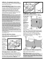
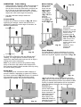
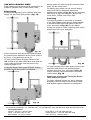
Maxi Sliding Extension Table
ETA300
Assembly & Operating Instructions
Thank you for purchasing the Triton Maxi Sliding Extension Table ETA300 for use on your Triton
MK3 or Series 2000 Workcentre. Working with large, long or awkward workpieces will now be easy,
safe and accurate.
Note: Some components are stored inside the large round tubes for shipping.
Tools required: Philips-head screwdriver, two 10mm spanners, 13mm spanner, drill with 6.5mm
(1/4”) bit (MK3 & early model Series 2000 Workcentres only), mallet, tape measure.
Maxi Sliding Extension Table
ETA300
Fig. 1
14
14
15
12
10
Inset 52
8
9
2
7
5
6
4
11
9
1
6
8
5
9
7
3
6
2
Inset 3
5
1
10
7
1
13
Inset 1
2
26
27
28
29
29
26
26
25
Fig. 2
28
18 17
16
26
m
315m
1 ”
12 /2
m
315m
1 2”
12 /
20
22
Underside of Table
20
19
25
21
21
24
23
Fig. 3
Page 2
Fig. 4
36
34
33
38
37
32
23
X
6
23
18
16
Fig. 5
31
30
1
39
Fig. 6
X
Page 3
6.5mm
(1/4”).
Maxi Sliding Extension Table
Table Assembly
Qty.
Long Extrusion
2
Short Extrusion Ass’y
2
Scale
2
*Brace
2
Corner Bracket
4
Inner Bearing (smaller) 2
Outer Bearing (larger) 2
Fence Assembly
1
Fastener Bag 1 (Table)
Brace Bracket
4
Flange Nut M6
14
Hex Bolt M6 x 10
20
Hex Nut M6
8
Washer M6
20
Screw M6x16
4
Fence Clamp Assembly 2
Ref.
Outer Track Assembly Qty.
4
Outer Track
*Leg
*Foot
Leg Plate
Leg Clamp Assembly
11
Fastener Bag 2 (Outer Track)
13
Hex Bolt M6 x 40
Nyloc Nut M6
Screw M4 x 10
Square Nut M4
Height Stop
Coach Bolt M6 x 20
Round Knob with Nut
Angled Tube Closer
Flat Tube Closer
2
3
10
8
15
7
1
5
9
6
12
14
1
2
2
4
2
6
6
4
4
2
2
2
2
4
Ref.
29
20
19
21
28
ETA300
Inner Track Assembly
Qty.
Ref.
Inner Track
Support Bracket
Skid Assembly
Front Panel Bracket
Rear Panel Bracket
1
2
2
1
1
33
32
36
30
31
Fastener Bag 3 (packed in Bag 2)
22
23
26
27
17
16
18
24
25
Coach Bolt M6 x 20
Round Knob with nut
Coach Bolt M6 x 12
Washer M6
Locking Latch
Hex Bolt M6 x 45
Nyloc Nut M6
Screw M6 x 10
Flange Nut M6
2
2
4
4
2
2
6
2
2
16
18
34
6
37
38
23
39
1
* Packed inside inner & outer tracks
ASSEMBLING THE TABLE & RIP FENCE
STEP 1
Using the fasteners from Bag 1, insert 6 Flange
Nuts (1) into each Long Extrusion (2) as shown in
Inset 1, Fig. 1.
Turn the table over again (face down). Make sure
the corner brackets are pushed fully home into the
corners, and that the plastic corner blocks are still
fully inserted into the ends of the extrusions.
Tighten the 8 bolts holding the corner brackets. Do
not over-tighten. (Tighten each pair of bolts a little
at a time, to ensure you don’t distort the frame).
Lay out the two long extrusions and the two short
extrusions as shown in Fig. 1, making sure that all
of the flange nuts are facing inwards.
Next tighten the 8 bolts holding the brace brackets
to the long extrusions, and finally tighten the 4 bolts
through the braces.
Plug the corner blocks of the Short Extrusions (3)
into the ends of the long extrusions and tap fully
home with a mallet (or similar).
STEP 4
Plug the two smaller Inner Bearings (11) into the
corner blocks below the “380mm” scale readings
and tighten using the Countersunk Screws (12)
and Hex Nuts (9). The two longer Outer Bearings
(13) are fitted to the corner blocks near the
1220mm scale readings as shown in Fig. 1.
STEP 2
Turn the table over (face down, as in Fig. 2) on a
flat surface and loosely attach the Corner Brackets
(4), using the Hex Bolts (5) and Washers (6) into
the flange nuts. (Slide the flange nuts into position
using a screwdriver).
Ensure that the two printed corner brackets are
bolted with their correct edges on the same long
extrusion. See Fig. 1.
STEP 5
Take apart the Fence Clamp Assemblies (14) and
reassemble them through the slot in the Fence
Assembly (15) as shown in Fig. 1.
Loosely fit the Brace Brackets (7) to the Braces
(8) using Hex Bolts (5), Washers (6) and Hex Nuts
(9). See Inset 2, Fig 1.
Turn the table face up once again. With the clamp
assemblies loosened, lower the square feet on the
clamp bolts into two of the table corner blocks.
Slide the fence along the extrusions to position it
wherever you like, and tighten the round knob to
lock it in place.
Position the braces about 315mm in from each side
of the frame (See Fig. 2) and loosely attach the
braces with hex bolts and washers into the
remaining flange nuts. Do not tighten any of the
fasteners yet.
ASSEMBLING THE OUTER TRACK
STEP 6
Insert the Coach Bolts (16) through the slots in the
Legs (20), and fit the Height Stops (17) and Round
Knobs (18) onto them, as shown in Fig. 3.
There should be two flange nuts left over. These
can be used later for fitting jigs etc. Fig. 9.
STEP 3
Turn the table face upwards again and insert the
Scales (10) between the long extrusions and the
brace & corner brackets. Position them with the
380mm ends hard up against the short extrusion on
the “map of Australia” side of the table. Push the
scales down until they “click” into location, flush
with the top face of the long extrusions, as shown
in Inset 3 on Fig. 1.
Attach the Feet (19) to the legs using the Leg
Plates (21), Hex Bolts (22) and Nyloc Nuts (23) as
shown. Note: the raised bumps on the leg plates
must face inwards, touching the legs (see lower
Inset Fig. 3). The feet should face away from the
leg slots as shown.
Page 4
Note: if you have a MK3 Workcentre or an early
Series 2000 Workcentre (pre- serial no. 305000)
you will have to drill the lower holes through the
end panel flanges. If drilling, make sure you
position the holes as shown in the inset in Fig. 5,
to give you the full range of height adjustment in
the bracket. Centre punch the hole positions and
drill 1/4” or 6.5mm holes.
Tighten the bolt which passes through each leg
until the feet pivot smoothly. The foot is designed to
swing around on this bolt for easy storage.
STEP 7
Tap the Angled Tube Closers (24) into the bottoms
of the legs ensuring they are correctly oriented, as
shown. Tap the Flat Tube Closers (25) into the
remaining tube ends.
Fit the inner track to the Workcentre by locating the
coach bolt heads through the keyholes in the end
panel brackets as shown in Fig. 6. Tighten the
round knobs and then temporarily tighten the four
nyloc nuts (9) holding the inner track to the
brackets.
STEP 8
Loosely fit the Philips-Head Screws (26) and
Square Nuts (27) through the holes in each Clamp
Assembly (28) as shown in the top inset Fig. 3.
Tap the assemblies onto the ends of the Outer
Track (29) locating the screws in the notches.
ALIGNING THE TRACKS
STEP 12
On Series 2000 Workcentres, kick the legs of the
Workcentre diagonally outwards to ensure that it is
fully stable on the folding stand.
Loosen the large round knobs and align the cutouts
in the clamps with the square cutouts in the track.
Insert the legs through the track cut-outs and
tighten the large round knobs to clamp. Now tighten
the Philips-head screws (26). Slide the height
stops up the leg slots until they touch the outer
track and tighten into position. They help set the
correct height for future set ups, and serve as
protection against track slippage under heavy load.
Position the outer track parallel to the inner track
approximately 700mm away from it. Place the table
onto the tracks with the inner (smaller) bearings on
the inner track. Always fit the table in this
orientation. Slide the table to each end of its travel
and adjust the position of the outer track. The
lengthened outer bearings make this a non-critical
adjustment.
FITTING THE INNER TRACK
STEP 9
Loosely bolt the Support Brackets (32) to the
brackets on the Inner Track (33) using the short
Coach Bolts (34), Washers (6) and Nyloc Nuts (9),
as shown in Fig. 4. Do not yet tighten. Note the
orientation of the brackets in regard to the long
overhang of the inner track (marked “X” in Fig. 4).
STEP 13 - Adjusting Inner Track Height
Next you have to fine-tune the height of the inner
track. Fit the extension table fence to the sliding
table so that it extends across the Workcentre table
as shown in Fig. 12. Loosen the front bearing
channel bolt and adjust the height of the front panel
bracket until the bottom of the fence is around 0.5 1mm above the Workcentre table. Slide the table to
the rear of the workcentre and adjust the height of
the rear bracket. Tighten the bolts and Philips-head
screws holding the brackets to the end panels.
Loosely fasten the longer Coach Bolts (16) and
Round Knobs (18) onto the support brackets as
shown in Fig. 4.
Undo the large round knob (one turn only) on each
Skid Assembly (36) and insert them into the ends
of the inner track. With the skids pointing up as
shown, firmly tighten the knobs.
STEP 14 - Adjusting Outer Track Height
Next, adjust the height of the outer track until the
fence is level, and parallel to the Workcentre table.
STEP 10
Fasten the two Locking Latches (37) onto the latch
brackets using the Hex Bolts (38) and Nyloc Nuts
(23). Ensure the rectangular windows in the
latches are oriented as shown in Fig. 4. Tighten
the bolts until the latches pivot firmly.
Check the table throughout its travel for diagonal
rocking on the tracks, and fine tune the height of
the outer track if necessary. Adjust the height stops
on the outer track legs to lock in the correct height.
With the sliding table positioned midway along the
tracks, engage the
front and rear locking
latches (Fig. 7).
STEP 11
Fit the End Panel Brackets (30) and (31) to the
left-hand side of the Workcentre (when viewed from
the front panel, which has the switchbox). The
brackets are handed... the long edge flanges
should wrap around the faces of the end panels.
See Fig. 5.
Adjust the PhilipsHead screws until
the heads enter the
rectangular windows
and the table cannot
be lifted. (You will
have to unlock the
latches and lift the
table clear to make
these adjustments). Fig. 7
At the top of each bracket, use the bolt, washer
and nut which hold the left-hand bearing channel in
position. At the bottom of each bracket, fit the
Philips-Head Screw (39) and flange nut (1),
but do not tighten yet.
Page 5
STEP 15 - Fine-tuning the Inner Track
The last step is to fine-tune the inner track position
in the horizontal plane, to ensure that the extension
table scales are accurate.
Fig. 9
Series 2000 Workcentres: With the extension
table fitted and locked, and the rip fence removed,
insert the standard Workcentre rip fence and set it
to 500mm using the end panel calibration marks.
Loosen the four nyloc nuts on the inner track
support brackets and adjust the inner track
sideways until both front and rear scales read
exactly 500mm, when sighting down the front face
of the Workcentre rip fence. Tighten the four nuts
and remove the Workcentre rip fence.
OPERATING - Table Locked
Lock the table using the front and rear locking
latches and fit the rip fence as shown in Fig. 10.
Set your width
by sighting the
Fig. 10
scales down
the front face
of the fence.
Ensure the
fence is
always set
parallel to the
blade. Turn
the hold-down
clamps around
so they don’t
overhang the
workpiece.
MK3 Workcentres: Extend the extension table
fence across the Workcentre until the tip is level
with the left-hand edge of the saw slot. Check for
parallel by sliding the extension table so that the
fence tip runs the length of the saw slot. Loosen
the four nyloc nuts on the inner track support
brackets and adjust the position of the track until
the fence tip aligns perfectly with the saw slot at
both ends of the table travel.
To ensure the correct scale reading, position the
extension table with the front scale level with the
front of the saw blade and measure from the blade
teeth to check the scale reading. Adjust the position
of the inner track if necessary until the scales are
accurate, ensuring the track is moved by exactly
the same amount at each end.
Finally, double check the parallel alignment and
scale accuracy by repeating the above steps, or by
making a test cut.
Ensure that the overhead guard is lowered onto the
workpiece. Press the sheet against the fence at all
times. When ripping large sheets the plastic skids
at the ends of the inner track will provide additional
support. However when handling very large
workpieces it is best to use Triton Multi-Stands
(shown holding a length of wood in Fig. 11) or
have someone assist you.
Your Sliding Extension Table is now fully assembled
and ready for use.
Using the Hold-Down Clamps
When cutting large or awkward pieces in any of the
Sliding Table modes, you should secure your
workpiece using the hold-down clamps.
Fig. 11
Swing the
fence clamps Fig. 8
around until
the hold-down
feet overhang
the
workpiece.
With the
fence locked,
lower the feet
until they
press firmly
on the
workpiece by
spinning the thumb wheels clockwise. See Fig. 8.
When ripping thin workpieces you may need to fit
an edge support (Inset - Fig. 11) against the rip
fence, to prevent the corner of the workpiece from
dipping into the table openings.
Attaching Fixtures to the Fence
Two additional flange nuts have been provided in
Bag 1 for attaching fixtures or sub-fences to the rip
fence. Rotate the fence clamps so the rear is level
with the front face of the rip fence. Insert the flange
nuts into the slots as shown in Fig. 9 and attach
your fixture using M6 bolts (not supplied).
MK3 Workcentres: to rip in the 260mm 380mm range, clamp a 1200mm long x 200mm
wide packer to the extension table fence, using the
hold-down clamps. When setting the desired width,
remember to add 200mm.
Page 6
OPERATING - Table Sliding
• Always slide the extension table the full length of
the tracks before making your cut. Check that
the rip fence clears the saw blade, and does not
hit or ride up on the Workcentre table. Check
that the sliding table does not rock on its tracks.
Adjust the outer track height if necessary.
Mitre Cutting
Mitres can be
cut with the
fence set at a
trailing angle
(Fig. 14) or
leading angle
(Fig. 15) and
with the
workpiece in
front (Fig. 14)
or behind the
fence. (Fig. 15)
• Use the hold-down clamps whenever
possible.
Crosscutting
Position the rip fence as shown in Fig. 12. When
tightening the clamps, ensure that the fence is
pulled fully toward the outer edge of the table, for
absolute squareness.
Fig. 14
Fig. 15
You can use the
Workcentre
protractor to set the
desired mitre angle.
Place it in the
protractor slot as
shown in Fig. 15.
Align the extension
table fence to the
protractor in the
position which best
suits your
workpiece, then
remove the
protractor.
Taper Ripping
For slight tapers on large workpieces (ie. doors),
set the extension table fence to Panel Saw mode
and insert a packer against it as shown in Fig. 16.
Fig. 12
For gauging lengths up to 1220mm, you can align
the end of the workpiece with the desired scale
reading. For longer pieces, touch the fence tip
against the saw blade teeth and use this to align a
cutting mark on the workpiece.
Note: if you wish to prevent the gradual cutting
away of the fence tips (which were designed for
this purpose) attach a small wooden fence tip using
the screw holes provided.
Panel Saw
This position gives a maximum width capacity of
around 1220mm, depending on saw size. Position
the fence as shown in Fig. 13. Ensure it is pushed
fully toward the outer edge of the table before
tightening the clamps, for absolute squareness.
Fig. 16
Tapers can also be cut by angling the rip fence.
(Fig. 17) The required angle can be achieved by
using the Workcentre protractor as outlined in Mitre
Cutting. A parallel sided packer will be required to
offset the distance between the fence and the
protractor in
establishing the
correct taper angle.
If the fence holddown clamps do not
adequately secure
your work when
taper ripping, use
additional means of
clamping the work to
the sliding table.
Fig. 13
Page 7
USE WITH A ROUTER TABLE
Edge planing and trenching can be performed in all
modes of operation with a Triton Router Table.
Edge Planing
For edge planing pieces up to 1220mm wide, any
length, use the Fixed Table position (Fig. 18).
Always guide your work along the extension table
fence, not the router fence.
For planing long edges you can use the sliding
table mode with the extension table fence
positioned as shown in Fig. 19. Use the extension
table fence to align the workpiece, and set the
router fence, if fitted, clear of the work.
Trenching
Trenching is possible in all modes of operation.
In the Table Sliding mode clamp a wooden batten
to extension table fence and extend it past the
cutter, as shown in Fig. 20. Run the batten
through the cutter to create a sighting notch and to
prevent tear-out in your workpiece.
Fig. 18
Set the extension table fence to the desired width
by measuring the distance from the router cutter to
the fence, or by performing a test cut.
On early model Router & Jigsaw Tables set the
rear section of the router table fence flush with the
router cutter and set the front sub-fence to the
maximum depth of cut.
If using the Router Table model RTA300, remove
the fence and fit the guard to the tabletop.
Fig. 20
For long trenches in the Table Sliding mode fit the
extension table fence in the leading position
(furthest away from you), as shown in Fig. 19.
Longer trenches can be performed in the Table
Locked mode, Fig. 18.
Always use extreme care if using the Router
Table without the guard.
For large, awkward objects (eg. heavy staircase
stringers) it may be best to use the router handheld against a guide clamped to the workpiece.
Fig. 19
Made in Australia by: Triton Manufacturing & Design Co. Pty. Ltd. ACN 000 195 951 ABN 43 000 195 951
14-18 Mills St, Cheltenham, Vic. Australia 3192 Ph: (03) 9584 6977 Fax: (03) 9584 5510 Web Site: http://triton.net.au
International Offices:
Canada - Toll Free: 1 888 874 8661
South Africa - Free Call: 0800 600 432
Japan - Free Call: 0120 171 079
United Kingdom - Free Call: 0800 856 7600
New Zealand - Ph: (09) 415 2545
USA - Toll Free: 1 888 874 8661
PUA518
8.01