1
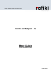
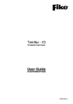
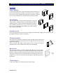
Manual Call Point Installation and Operating Instructions - Twinflex
Installation
Surface Mounting
Fix the surface back box to a flat vertical surface using at least two of
the four mounting holes provided. The back box may be drilled to
allow cable access as required and a 20mm hole is already provided at
the rear. Zone cabling may be connected to the terminals provided.
Flush Mounting
The Call Point may be flush mounted utilising the optional
‘adapter-plate’, combined with any standard single gang flush
mounting back box (with a minimum internal depth of 25mm).
After installing the back box securely, attach the bezel using
the two screws provided, and terminate your cables directly
into a flying terminal block.
Installation 2nd Fix
Once all testing has been carried out on the cabling and ‘continuity & integrity’ has been proven, then
the Manual Call Point unit may be installed.
Call Point Installation
The Call Point is installed by locating the upper mounting spigots into the back
box and then pushing the unit gently home. The single fixing screw may then be
tightened as required.
Please remember that all high voltage testing must be carried out before the
installation of the Call Point front unit as this may cause damage.
Reset and Test
The Call Point contains a resettable element, which latches in position when
operated and does not need to be replaced. Inserting the key as shown and
turning it clockwise until the element clicks back into place will reset the unit.
Testing the Call Point may be carried out either by pressing the element or by
using the key in the same manner as for resetting but without having pressed
the element
Technical Support
Contact your supplier for technical support on this product.
26-0356 Issue 6
Manual Call Point Installation and Operating Instructions - Twinflex
The Manual Call Point is available with or without an integral alarm sounder. If
your device has no sounder then ignore all reference to integral sounders on these
installation instructions. This device is compatible only with Twinflex control panels
and their associated detection and alarm equipment and may be installed on the
same zone as the Multipoint detector/sounder, Hatari sounders and input/output
modules.
The cabling should be 2c1.5 screened and fire resistant, of an MICC or FP200
equivalent type and is to be in the form of a 2-core radial circuit terminating at the
End of Line device.
The indicating LED will light on operation of the device and switch off on resetting
both the device and the control panel. Remember that the ‘End of Line’ device needs
its EOL signal activated with its dil switches as below. Do not use a resistor as an
End of Line device.
NB/ Red = zone +ve, Blue = zone 0V
Dil Switch Settings
Sound Patterns
Single Tone – 970 Hz
Dual Tone UK Evacuate – 800 & 970 Hz
Slow Whoop Up - 500 to 1200 Hz sweep up
Dual Tone French Warble – 440 & 550 hZ
High
Low
Enabled
Disabled
Sound Levels
End of line
1
ON
OFF
OFF
ON
-
2
ON
ON
OFF
OFF
-
Technical Data
Dimensions;
.
.
width x height .
= 87mm x 87mm ,
flush depth protruding
= 25mm,
surface depth
.
= 53mm.
Operating temperature; .
.
.
.
= -25’C to 65’C.
Voltage Range; .
.
.
.
.
= 18 to 35v DC
Operating Current;
.
Quiescent
.
= 105uA (Typical)
MCP Alarm
.
= 25 mA
Sounder High
.
= 16 mA
Sounder Low
.
= 8mA
Sound Pressure Outputs; Sounder High
.
= 85dB(A)
Sounder Low
.
= 72dB(A)
LED Operation;
.
Alarm indication = Continuous
EOL indication .
= flash at 5 second intervals
26-0356 Issue 6
3
ON
OFF
-
4
ON
OFF