1
Installation and Troubleshooting Guide
All rights reserved. Reproduction or use of content, in any manner, without express written permission by CDI Electronics, Inc., is prohibited.
CDI P/N: 114-7509
NOTE: This unit replaces all 827509A1, A3, A7, A9, A10 AND T4 series CDM Modules
This product is designed for installation by a professional marine mechanic. CDI cannot be held liable for injury or damage resulting
from improper installation, abuse, neglect or misuse of this product.
INSTALLATION
1.
2.
3.
4.
5.
6.
7.
8.
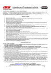
Disconnect and clean all engine and battery ground wires.
Disconnect the old CDM Module and remove the high tension coil wire from the spark plug.
Unbolt and remove the old CDM Module. (Note the direction of the spark plug wire).
Check for DC voltage on the kill (stop) wires (usually Black/Yellow) with the key-switch in the on and off position. At no time should you see over 2
volts DC on this wire as severe damage to the power pack can occur.
Apply a light amount of dielectric grease (i.e. CDI 991-9705) to the seal area of the wire connector from the engine harness.
Apply a light amount of dielectric grease to the outside of the new spark plug wire and thread the spark plug wire into the new CDM Module.
Bolt the new CDM Module onto the engine (orient the new CDM Module so that the spark plug wire is pointed in the same direction as the original).
Plug in the connector from the wire harness into the new CDM Module and connect the spark plug wire to the spark plug.
TROUBLESHOOTING
NO SPARK:
SERVICE NOTE: A 511-5207A 1 CDM Test Harness is highly recommended for testing these parts.
1. Disconnect the black/yellow kill wires from the harness and retest. If the engine’s ignition fires now, the kill circuit has a fault-possibly the key
switch, harness or shift switch.
2. Install a 511-5207A 1 test harness inline to one of the CDM Modules and unplug the Black/Yellow wires in the harness. This will isolate that CDM
from all other connections. If spark returns on that CDM with the Black/Yellow wires unplugged, test the remaining CDMs. If you disconnect one
CDM and all other CDMs start firing, the one the test harness is connected to is defective. Remember, the fault could be in the CDM harness.
3. Disconnect one CDM module at a time and see if the other modules start firing. If they do, the module you just unplugged is defective.
4. Disconnect the yellow wires from the stator to the rectifier and retest. If the engine fires, replace the rectifier.
5. Check the resistance of the Black wire in the 4 pin connector to the CDM, referenced to engine ground. It should show a short, less than 0.5 ohms.
A high reading or an open reading indicates a break in the Black wire. Check the wire at the ground terminal.
6. Check the cranking RPM. A cranking speed less than 250-RPM will not allow the system to fire properly.
7. Check the stator resistance and DVA output as given below:
WIRE
White/Green
White/Green
White/Green
Read To
Green/White
Green/White
Green/White
STATOR RESISTANCE
500-700 (2, 3, 4 Cyl)
380-430 (6 Cyl, 2.5L)
800-1200 (6 Cyl, 3.0L)
DVA
180V or more
180V or more
180V or more
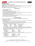
6. Check the resistance of the CDM as follows:
Red Meter Lead
Black Meter Lead
Reading
CDM Pin #
CDM Pin #
CDM Pin #
CDM Pin #
CDM Pin #
CDM Pin #
A
C
CDI 2200-2400 Ohms – OEM 1200-1300 ohms
D
A
DIODE*
A
D
DIODE*
D
B
DIODE*
B
D
DIODE*
A
B
DIODE*
High Tension Lead
A
OEM 700-1300 Ohms – CDI 2200-2400 Ohms
* Diode readings are to be read one way, then reverse the leads and read again. You should get a low reading in one direction and a higher
reading in the other.
INTERMITTANT SPARK OR NO SPARK ON ONE OR MORE CYLINDERS:
1.
2.
Check the resistance of the Black wire in the 4 pin connector to the CDM, referenced to engine ground. It should show a short, less than 0.5 ohms.
A high reading or an open reading indicates a break in the Black wire. Check the wire at the ground terminal.
If the cylinders are only acting up above an idle, connect an inductive Tachometer to all cylinders and try to isolate the problem cylinders.
SERICE NOTE: As these triggers have the Bias circuit built into them, you cannot meter them. Using a set of piercing probes, check the trigger DVA
output as given below:
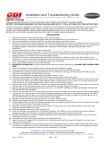
2 CYLINDER
Check From
Check to
Resistance
DVA Reading Connected Disconnected
Purple wire
Engine GND
Open
0.5V to 1.5V**
5V or more
White wire
Engine GND
Open
0.5V to 1.5V**
5V or more
**A DVA voltage reading that is close to the same reading connected as disconnected may indicate a broken ground wire.
1. If # 1 is not firing, disconnect #2 CDM module. Check which stator wire feed #2 CDM and using a jumper wire, short that side of the stator to engine
ground. If # 1 starts firing, replace the #2 CDM.
2. For #2 CDM not firing, short the stator wire that feeds the #1 CDM. Again, if the #2 CDM starts firing, replace the #1 CDM.
CDI Electronics • 353 James Record Road SW • Huntsville, AL 35824
Web Support: www.cdielectronics.com • Tech Support: 1-866-423-4832 • Order Parts: 1-800-467-3371
All rights reserved. Reproduction or use of content, in any manner, without express written permission by CDI Electronics, Inc., is prohibited.
Rev C • 5/14/13
Page - 1 of 3
QF-319
Installation and Troubleshooting Guide
All rights reserved. Reproduction or use of content, in any manner, without express written permission by CDI Electronics, Inc., is prohibited.
3 CYLINDER
Check From
Check to
Resistance
DVA Reading
Purple wire
Engine GND
Open
0.5V or more
White wire
Engine GND
Open
0.5V or more
Brown wire
Engine GND
Open
0.5V or more
For example, if #1 CDM is not firing: If # 1 is not firing, disconnect #2 CDM module and see if the #1 module starts firing. If it
does, the #2 module is likely bad. If still no fire on #1 CDM, reconnect #2 CDM and disconnect #3 CDM module and see if
the #1 module starts firing. If it does, the #3 module is likely bad. If no change at this point, swap the #3 and #1 CDM
modules. If the problem moves to another cylinder, replace the CDM that was on #1 cylinder. If no change, swap the
Green/White and White/Green wires. If fire changes, replace the stator. When moving CDM modules around on the engine,
pay attention to the stator wire colors going to the CDMs. You must have a Green/White and White/Green wire connected or
you will lose fire on all CDMs. Follow these guidelines for whichever CDM is not firing.
Check From
Brown wire
White wire
Purple wire
Blue wire
Check to
Engine GND
Engine GND
Engine GND
Engine GND
4 CYLINDER
Resistance
Open
Open
Open
Open
DVA Reading
0.5V or more
0.5V or more
0.5V or more
0.5V or more
When moving CDM modules around on the engine, pay attention to the stator wire colors going to the CDMs. You must
have a Green/White and White/Green wire connected or you will lose fire on all CDMs. Whichever CDM is not firing,
disconnect it and one of the other CDMs on the opposite side of the stator. Try to get two CDMs firing and swap connections
on each side to isolate the problem CDM. Remember, a CDM on one side of the stator wire can stop the other CDMs on the
opposite side of the stator.
For example, if # 1 is not firing, disconnect #2 CDM module and see if the #1 module starts firing. If it does, the #2 module is
likely bad. If still no fire on #1 CDM, reconnect #2 CDM and disconnect #3 CDM module and see if the #1 module starts
firing. If it does, the #3 module is likely bad. If no change at this point, swap the #3 and #1 CDM modules. If the problem
moves to another cylinder, replace the CDM that was on #1 cylinder. If no change, swap the Green/White and White/Green
wires. If fire changes, replace the stator.
CDI Electronics • 353 James Record Road SW • Huntsville, AL 35824
Web Support: www.cdielectronics.com • Tech Support: 1-866-423-4832 • Order Parts: 1-800-467-3371
All rights reserved. Reproduction or use of content, in any manner, without express written permission by CDI Electronics, Inc., is prohibited.
Rev C • 5/14/13
Page - 2 of 3
QF-319
Installation and Troubleshooting Guide
All rights reserved. Reproduction or use of content, in any manner, without express written permission by CDI Electronics, Inc., is prohibited.
6 CYLINDER
1. Check the stator resistance as shown:
WIRE
Read To
White/Green
Green/White
White/Green
Green/White
White/Green
Green/White
STATOR RESISTANCE
500-700 (2, 3, 4 Cyl)
380-430 (6 Cyl, 2.5L)
800-1200 (6 Cyl, 3.0L)
DVA
180V or more
180V or more
180V or more
2. Check the trigger resistance as shown:
Check From
Check to
OEM Resistance CDI Resistance
DVA Reading
Purple wire
Blue
1100-1400
800-1050
0.5V or more
White wire
Red
1100-1400
800-1050
0.5V or more
Brown wire
Yellow
1100-1400
800-1050
0.5V or more
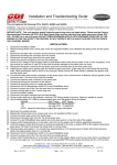
The connection guide below will assist you in locating areas where problems can occur. Remember a short in either #1, #2 or #3 can cause either # 4,
#5 and #6 not to have spark.
HIGH SPEED MISS:
1.
2.
3.
4.
5.
Connect an inductive Tachometer to all cylinders and try to isolate the problem. A high variance in RPM on one cylinder indicates a problem usually
in the trigger or CDM module.
Perform a high-speed shutdown and read the spark plugs. Check for water. A crack in the block can cause a high speed miss when the water
pressure gets high, but a normal shutdown will mask the problem.
Remove the flywheel and check the triggering and charge coil flywheel magnets for cracks or broken magnets.
Disconnect the yellow wires from the stator to the rectifier and retest. If the engine fires, replace the rectifier.
Rotate the stator one bolt hole in either direction and re-test. If the miss is gone, leave the engine as is if you applied a thread locker to the stator
screws.
CDI Electronics • 353 James Record Road SW • Huntsville, AL 35824
Web Support: www.cdielectronics.com • Tech Support: 1-866-423-4832 • Order Parts: 1-800-467-3371
All rights reserved. Reproduction or use of content, in any manner, without express written permission by CDI Electronics, Inc., is prohibited.
Rev C • 5/14/13
Page - 3 of 3
QF-319