1
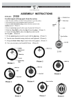
Installation and Troubleshooting Guide
All rights reserved. Reproduction or use of content, in any manner, without express written permission by CDI Electronics, Inc., is prohibited.
CDI P/N: 173-4766
This stator replaces P/N: 583779, 584236 and 584766
WARNING! This product is designed to be installed by a professional marine mechanic. CDI Electronics cannot be held liable for injury
or damage resulting from improper installation, abuse, neglect or misuse of this product.
SERVICE NOTE: Discoloration of all the battery windings is an indication of a problem in the rectifier/regulator. Discoloration of only
one post of the battery windings indicates a problem in the stator.
INSTALLATION
1.
2.
3.
4.
5.
6.
7.
8.
9.
10.
Remove the negative battery cable.
Remove the flywheel.
Disconnect the original stator wires.
Remove the Black/Yellow kill wire from the old stator’s 5 pin connector.
Remove the original stator, saving the original bolts.
Install the new stator using the original bolts with a good thread-locker applied (CDI 989-3977 is recommended) to the
bolts and tightened to the factory torque specifications.
Install the Black/Yellow kill wire in the new stator’s 5 pin connector empty hole.
Connect the new stator to the power pack.
Connect the new stator to the regulator/rectifier (ignore any stripes on the rectifier as the new stator does not require
the Yellow wires to be connected to a particular rectifier wire).
Replace the flywheel according to the service manual.
TROUBLESHOOTING
Service Note: Please use the Factory recommended spark plug (currently Champion QL77JC4) gapped at 0.030”.
NO SPARK ON ANY CYLINDER:
1.
2.
3.
4.
5.
6.
7.
8.
9.
Disconnect the black yellow stop wire and retest. If the engine's ignition has spark, the stop circuit has a fault-check the key switch,
harness and shift switch.
Disconnect the yellow wires from the rectifier and retest. If the engine now sparks, replace the rectifier.
Check the stator resistance. Reading should be about 500 ohms from the brown wire to brown/yellow wire.
Check the DVA output from the stator. You should have a reading of at least 150V or more from the brown wire to the brown/yellow
wire (while connected to the pack) and 12 Volts on the Orange to Orange/Black power coil wires.
Check the resistance and DVA output of the Timer Base:
Read from
Read to
Reading
DVA (connected to pack)
Blue Trigger wire
White
10-20 ohms
0.5 Volts Minimum
Purple Trigger wire
White
10-20 ohms
0.5 Volts Minimum
Green Trigger wire
White
10-20 ohms
0.5 Volts Minimum
Check the DVA voltage on the Black/Yellow wire to engine ground. You should have a reading of at least 150V or more (while
connected to the pack). If the reading is low, disconnect the stator 5 pin connector from the pack. Using a meter set to diode scale,
check from the Black/Yellow wire to the Brown (and Brown/Yellow) wires. You should show a high or no reading at all. If you show
a normal diode reading, the kill (Stop) diode is shorted and the pack needs to be replaced.
Check the resistance of the power pack SCR’s:
Read from
Read to
Reading
Blue Trigger wire
Orange/Blue
110 ohms*
Purple Trigger wire
Orange
110 ohms*
Green Trigger wire
Orange/Green
110 ohms*
*Readings will vary slightly depending upon your meter. Readings should be fairly consistent.
Check the kickback diodes connected to the power pack’s SCR’s, using a meter set to diode scale. If the readings show a short or
open, replace the power pack.
Red meter lead
Black meter lead
Reading
Black Ground wire
Orange/Blue
0.500**
Black Ground wire
Orange or Orange /Violet 0.500**
Black Ground wire
Orange/Green
0.500**
** The actual reading will vary, depending upon your meter.
Check the cranking RPM. A cranking speed of less than 250-RPM will not allow the system to fire properly.
CDI Electronics • 353 James Record Road SW • Huntsville, AL 35824
Web Support: www.cdielectronics.com • Tech Support: 1-866-423-4832 • Order Parts: 1-800-467-3371
All rights reserved. Reproduction or use of content, in any manner, without express written permission by CDI Electronics, Inc., is prohibited.
Rev C • 1/29/14
Page - 1 of 3
QF-319
Installation and Troubleshooting Guide
All rights reserved. Reproduction or use of content, in any manner, without express written permission by CDI Electronics, Inc., is prohibited.
NO SPARK OR INTERMITTENT ON ONE OR MORE CYLINDERS:
1.
2.
Check the resistance and DVA output of the Timer Base:
Read from
Read to
Reading
DVA (connected to pack)
Blue Trigger wire
White
10-20 ohms
0.5 Volts Minimum
Purple Trigger wire
White
10-20 ohms
0.5 Volts Minimum
Green Trigger wire
White
10-20 ohms
0.5 Volts Minimum
Check the DVA output on the orange wires from the power pack while connected to the ignition coils. You should have a reading of
at least 150V or more. If the reading is low on one cylinder, disconnect the orange wire from the ignition coil for that cylinder and
reconnect it to a load resistor. Retest. If the reading is now good, the ignition coil is likely bad. A continued low reading indicates a
bad power pack or Timer Base (test per above).
ENGINE WILL NOT ACCELERATE OVE 2500 RPM AND SHAKES HARD (SLOW ACTIVATED)
1.
2.
3.
4.
Use a temperature probe and verify that the engine is not overheating.
Disconnect the Tan temperature wire from the pack and retest. If the engine now performs properly, check the temperature switch,
harness and SystemCheck Gauge.
Make sure the Tan temperature switch wire is not located next to a spark plug wire.
If the engine will not rev above 2500 and the Tan wire is disconnected from the power pack (and not near a spark plug wire), the
pack is defective.
CDI Electronics • 353 James Record Road SW • Huntsville, AL 35824
Web Support: www.cdielectronics.com • Tech Support: 1-866-423-4832 • Order Parts: 1-800-467-3371
All rights reserved. Reproduction or use of content, in any manner, without express written permission by CDI Electronics, Inc., is prohibited.
Rev C • 1/29/14
Page - 2 of 3
QF-319
Installation and Troubleshooting Guide
All rights reserved. Reproduction or use of content, in any manner, without express written permission by CDI Electronics, Inc., is prohibited.
T E C H N I C A L S E R V I C E BU L L E T I N
Reference Information OMC Outboard Service Bulletin 2276 Rev 1 April 1994
No. 032510
Mar, 2003
Subject:
Make:
Horsepower:
Years:
Engine Over-Heating
Johnson & Evinrude
50 HP
60 HP
1986-94
1986-94
65 HP
1987-94
70 HP
1989-94
Problem: The engine and electrical system can become damaged due to over-heating when air is trapped in the upper
half of the cooling system. Trapped air can cause the upper cylinder or regulator/rectifier to overheat, resulting
in damage to the piston or the regulator/rectifier (possibly burning out and damaging the stator also).
Air can become trapped when:
1.
The engine is idling with a blocked or restricted thermostat bypass hole.
2.
The engine is operated in aerated water, such as a pontoon or deck boat wakes.
Solution: Relocate the water pump indicator outlet tee (for the pee tube) from the side of the engine block to the top of
the engine block. This allows air to be vented from the top of the cooling system and helps ensure an adequate
water level when idling.
If the engine does not have a threaded hole located in the top of the cylinder block, please follow the steps below:
1. Remove the indicator hose from the outlet tee and discard it.
2. Remove the outlet tee.
th
3. Install a 1/8 NPT Brass pipe plug into the hole where the tee was located (use Gelseal on the threads).
4. Measure 2 inches forward from the rear corner of the exhaust manifold cover( ref “A”) and 1-3/8 inches from the
exhaust cover gasket (ref “B”. Mark the intersection with a center punch (see figure 2).
nd
5. Mark an 11/32 (Letter “R”) drill bit ½ inch from the tip (to prevent damage to the water jacket) as a depth gauge.
Grease the tip of the drill bit and drill a hole through the casting. The grease will help prevent metal shavings from
entering the cooling system.
6. Grease the tip of an 1/8 inch NPT tap and thread the hole. Be careful to not over tap the hole (over tapping may
not allow the adapter from sealing off).
7. Apply Gel Seal to the threads of the original tee and install it into the hole you just tapped. Position the tee so the
nipple is facing the rear of the engine.
th
8. Install a new piece of 3/16 rubber hose (19 inches long) from the tee to the indicator.
CDI Electronics • 353 James Record Road SW • Huntsville, AL 35824
Web Support: www.cdielectronics.com • Tech Support: 1-866-423-4832 • Order Parts: 1-800-467-3371
All rights reserved. Reproduction or use of content, in any manner, without express written permission by CDI Electronics, Inc., is prohibited.
Rev C • 1/29/14
Page - 3 of 3
QF-319