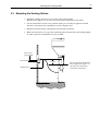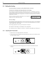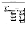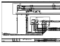
1
Westfalia
Landtechnik
Operating Instructions and Spare Parts List
7163--9001--045
07--2002 as of Program Version 01.01
Automatic Calf Feeder PREMIUM BOY / PREMIUM BIG BOY SM Powder
TAP5--SM2--27--F1
TAP5--SM2--28--P1
TAP5--SM2--30--P1
(DAIRY PROGRAM controlled by CALFSCAN)
Westfalia Landtechnik GmbH
Werner-Habig-Straße 1 - D-59302 Oelde
Telefon (02522) 77-0 - Telefax (02522) 77-2488
Postanschrift:
Westfalia Landtechnik GmbH
D-59299 Oelde
Printed in F.R.Germany
Table of contents
1
Introduction . . . . . . . . . . . . . . . . . . . . . . . . . . . . . . . . . . . . . . . . . . . . . . . . . . . . . . . . . . .
1.1
1.2
1.3
1.4
2
3
4
5
6
7
8
9
3
6
Safety Instructions . . . . . . . . . . . . . . . . . . . . . . . . . . . . . . . . . . . . . . . . . . . . . . . . . . . . . . . . . . . . . . .
Danger Signs on the Automatic Calf Feeder . . . . . . . . . . . . . . . . . . . . . . . . . . . . . . . . . . . . . . . . .
Information Signs on the Automatic Calf Feeder . . . . . . . . . . . . . . . . . . . . . . . . . . . . . . . . . . . . . .
Construction Parts System--Machine Powder . . . . . . . . . . . . . . . . . . . . . . . . . . . . . . . . . . . . . . . .
1.4.1 Motherboard and Distribution Board SM 2 Plus . . . . . . . . . . . . . . . . . . . . . . . . . . . . . . . . .
1.4.2 Water Heating in the Boiler . . . . . . . . . . . . . . . . . . . . . . . . . . . . . . . . . . . . . . . . . . . . . . . . . . .
1.4.3 Hand--Actuated Feeding Pump . . . . . . . . . . . . . . . . . . . . . . . . . . . . . . . . . . . . . . . . . . . . . . .
6
7
7
8
10
11
12
Specifications Automatic Calf Feeder . . . . . . . . . . . . . . . . . . . . . . . . . . . . . . . . . . .
13
Locating the Automatic Calf Feeder . . . . . . . . . . . . . . . . . . . . . . . . . . . . . . . . . . . . .
14
3.1
3.2
3.3
3.4
3.5
3.6
Local Electrical Connection . . . . . . . . . . . . . . . . . . . . . . . . . . . . . . . . . . . . . . . . . . . . . . . . . . . . . . . .
Installing the Automatic Calf Feeder . . . . . . . . . . . . . . . . . . . . . . . . . . . . . . . . . . . . . . . . . . . . . . . .
Mounting the Sucking Station . . . . . . . . . . . . . . . . . . . . . . . . . . . . . . . . . . . . . . . . . . . . . . . . . . . . . .
Mounting the Race--Way . . . . . . . . . . . . . . . . . . . . . . . . . . . . . . . . . . . . . . . . . . . . . . . . . . . . . . . . . .
Connecting the Micro--Identification “Calfscan” . . . . . . . . . . . . . . . . . . . . . . . . . . . . . . . . . . . . . . .
Water Connection . . . . . . . . . . . . . . . . . . . . . . . . . . . . . . . . . . . . . . . . . . . . . . . . . . . . . . . . . . . . . . . .
14
14
15
16
16
17
Operating Elements . . . . . . . . . . . . . . . . . . . . . . . . . . . . . . . . . . . . . . . . . . . . . . . . . . . .
18
4.1 Keyboard . . . . . . . . . . . . . . . . . . . . . . . . . . . . . . . . . . . . . . . . . . . . . . . . . . . . . . . . . . . . . . . . . . . . . . .
4.1.1 Operational Control Keys . . . . . . . . . . . . . . . . . . . . . . . . . . . . . . . . . . . . . . . . . . . . . . . . . . . .
4.1.2 Entering the Values . . . . . . . . . . . . . . . . . . . . . . . . . . . . . . . . . . . . . . . . . . . . . . . . . . . . . . . . .
4.1.3 Selecting the Options . . . . . . . . . . . . . . . . . . . . . . . . . . . . . . . . . . . . . . . . . . . . . . . . . . . . . . .
18
19
20
21
Installing the Automatic Feeder . . . . . . . . . . . . . . . . . . . . . . . . . . . . . . . . . . . . . . . . .
22
5.1
5.2
5.3
5.4
5.5
Connecting the Automatic Feeder to the Mains Supply . . . . . . . . . . . . . . . . . . . . . . . . . . . . . . . .
Filling the Boiler with Water . . . . . . . . . . . . . . . . . . . . . . . . . . . . . . . . . . . . . . . . . . . . . . . . . . . . . . . .
Filling the Milk Powder into the Powder Hopper . . . . . . . . . . . . . . . . . . . . . . . . . . . . . . . . . . . . . .
Calibrating the Feed Components . . . . . . . . . . . . . . . . . . . . . . . . . . . . . . . . . . . . . . . . . . . . . . . . . .
Setting the Heating . . . . . . . . . . . . . . . . . . . . . . . . . . . . . . . . . . . . . . . . . . . . . . . . . . . . . . . . . . . . . . .
5.5.1 Adjusting the Thermostats . . . . . . . . . . . . . . . . . . . . . . . . . . . . . . . . . . . . . . . . . . . . . . . . . . .
5.5.2 Recommendations for Temperature Settings . . . . . . . . . . . . . . . . . . . . . . . . . . . . . . . . . . .
5.5.3 Measuring the Temperature . . . . . . . . . . . . . . . . . . . . . . . . . . . . . . . . . . . . . . . . . . . . . . . . . .
5.6 Heating for Milk Powder Outlet and Protection against Frost . . . . . . . . . . . . . . . . . . . . . . . . . . .
22
22
22
22
24
24
25
25
26
Functioning of the Automatic Calf Feeder . . . . . . . . . . . . . . . . . . . . . . . . . . . . . . .
27
6.1 Preparing the Milk Portions . . . . . . . . . . . . . . . . . . . . . . . . . . . . . . . . . . . . . . . . . . . . . . . . . . . . . . . .
6.2 Distributing the Milk . . . . . . . . . . . . . . . . . . . . . . . . . . . . . . . . . . . . . . . . . . . . . . . . . . . . . . . . . . . . . .
6.2.1 In the Restricted Mode . . . . . . . . . . . . . . . . . . . . . . . . . . . . . . . . . . . . . . . . . . . . . . . . . . . . . .
6.2.2 In the Ad Libitum Mode . . . . . . . . . . . . . . . . . . . . . . . . . . . . . . . . . . . . . . . . . . . . . . . . . . . . . .
27
27
27
27
Settings in Setup . . . . . . . . . . . . . . . . . . . . . . . . . . . . . . . . . . . . . . . . . . . . . . . . . . . . . .
28
7.1 Different selections in Setup . . . . . . . . . . . . . . . . . . . . . . . . . . . . . . . . . . . . . . . . . . . . . . . . . . . . . . .
7.2 Function Table „Setup“ . . . . . . . . . . . . . . . . . . . . . . . . . . . . . . . . . . . . . . . . . . . . . . . . . . . . . . . . . . . .
7.3 How to make entries in Setup . . . . . . . . . . . . . . . . . . . . . . . . . . . . . . . . . . . . . . . . . . . . . . . . . . . . . .
28
30
31
Connecting the System-- Machine to the Feeding Computer . . . . . . . . . . . . . . .
32
8.1 Connecting the System--Machine to the VC3--Bus . . . . . . . . . . . . . . . . . . . . . . . . . . . . . . . . . . . .
32
Entries on the Feed Computer . . . . . . . . . . . . . . . . . . . . . . . . . . . . . . . . . . . . . . . . . .
34
9.1 Setup in DP5 . . . . . . . . . . . . . . . . . . . . . . . . . . . . . . . . . . . . . . . . . . . . . . . . . . . . . . . . . . . . . . . . . . . .
9.2 Setup in DP4.4 . . . . . . . . . . . . . . . . . . . . . . . . . . . . . . . . . . . . . . . . . . . . . . . . . . . . . . . . . . . . . . . . . .
34
40
4
Table of contents
9.3
9.4
9.5
9.6
10
11
12
13
14
Setup in C16 . . . . . . . . . . . . . . . . . . . . . . . . . . . . . . . . . . . . . . . . . . . . . . . . . . . . . . . . . . . . . . . . . . . .
Setup Related to the Automatic Feeder . . . . . . . . . . . . . . . . . . . . . . . . . . . . . . . . . . . . . . . . . . . . .
Settings for Animal--Specific Increase of the Concentration on C16 . . . . . . . . . . . . . . . . . . . . .
Settings for Animal--Specific Fresh Milk Ratio of the Feed Portion . . . . . . . . . . . . . . . . . . . . . .
43
43
44
44
Functions of the Menu Key . . . . . . . . . . . . . . . . . . . . . . . . . . . . . . . . . . . . . . . . . . . .
45
10.1 Hand Functions . . . . . . . . . . . . . . . . . . . . . . . . . . . . . . . . . . . . . . . . . . . . . . . . . . . . . . . . . . . . . . . . .
10.2 Portion Values . . . . . . . . . . . . . . . . . . . . . . . . . . . . . . . . . . . . . . . . . . . . . . . . . . . . . . . . . . . . . . . . . .
10.2.1 Selecting the Concentration . . . . . . . . . . . . . . . . . . . . . . . . . . . . . . . . . . . . . . . . . . . . . . . . .
10.2.2 Entering the Additive . . . . . . . . . . . . . . . . . . . . . . . . . . . . . . . . . . . . . . . . . . . . . . . . . . . . . . .
10.2.3 Restricted/Adlib--Mode . . . . . . . . . . . . . . . . . . . . . . . . . . . . . . . . . . . . . . . . . . . . . . . . . . . . .
10.3 Calibration . . . . . . . . . . . . . . . . . . . . . . . . . . . . . . . . . . . . . . . . . . . . . . . . . . . . . . . . . . . . . . . . . . . . .
10.3.1 Calibrating Water and MP . . . . . . . . . . . . . . . . . . . . . . . . . . . . . . . . . . . . . . . . . . . . . . . . . .
10.3.2 Calibrating Additives and Detergent . . . . . . . . . . . . . . . . . . . . . . . . . . . . . . . . . . . . . . . . . .
10.4 Machine Values . . . . . . . . . . . . . . . . . . . . . . . . . . . . . . . . . . . . . . . . . . . . . . . . . . . . . . . . . . . . . . . . .
10.4.1 Intermediate Mix . . . . . . . . . . . . . . . . . . . . . . . . . . . . . . . . . . . . . . . . . . . . . . . . . . . . . . . . . .
10.4.2 Mixer Afterrun . . . . . . . . . . . . . . . . . . . . . . . . . . . . . . . . . . . . . . . . . . . . . . . . . . . . . . . . . . . . .
10.4.3 Emptying Mixer . . . . . . . . . . . . . . . . . . . . . . . . . . . . . . . . . . . . . . . . . . . . . . . . . . . . . . . . . . .
10.4.4 Entering the Distribution Pause . . . . . . . . . . . . . . . . . . . . . . . . . . . . . . . . . . . . . . . . . . . . . .
10.4.5 Box 1 / Box 2 . . . . . . . . . . . . . . . . . . . . . . . . . . . . . . . . . . . . . . . . . . . . . . . . . . . . . . . . . . . . .
10.5 Diagnosis . . . . . . . . . . . . . . . . . . . . . . . . . . . . . . . . . . . . . . . . . . . . . . . . . . . . . . . . . . . . . . . . . . . . . .
10.5.1 Valves/Motors . . . . . . . . . . . . . . . . . . . . . . . . . . . . . . . . . . . . . . . . . . . . . . . . . . . . . . . . . . . . .
10.5.2 Sensors . . . . . . . . . . . . . . . . . . . . . . . . . . . . . . . . . . . . . . . . . . . . . . . . . . . . . . . . . . . . . . . . . .
10.5.3 Calibration . . . . . . . . . . . . . . . . . . . . . . . . . . . . . . . . . . . . . . . . . . . . . . . . . . . . . . . . . . . . . . . .
10.5.4 Identification . . . . . . . . . . . . . . . . . . . . . . . . . . . . . . . . . . . . . . . . . . . . . . . . . . . . . . . . . . . . . .
10.5.5 Checking . . . . . . . . . . . . . . . . . . . . . . . . . . . . . . . . . . . . . . . . . . . . . . . . . . . . . . . . . . . . . . . . .
10.6 Version . . . . . . . . . . . . . . . . . . . . . . . . . . . . . . . . . . . . . . . . . . . . . . . . . . . . . . . . . . . . . . . . . . . . . . . .
10.7 Function Table of the Menu Key for Connection to Bus--System . . . . . . . . . . . . . . . . . . . . . . .
45
46
46
46
47
47
47
49
49
49
50
50
50
51
51
51
52
52
52
53
53
54
Functions of the Automatic Key . . . . . . . . . . . . . . . . . . . . . . . . . . . . . . . . . . . . . . .
56
11.1 Display in the Automatic--Mode . . . . . . . . . . . . . . . . . . . . . . . . . . . . . . . . . . . . . . . . . . . . . . . . . . .
11.2 Releasing an Extra--Portion . . . . . . . . . . . . . . . . . . . . . . . . . . . . . . . . . . . . . . . . . . . . . . . . . . . . . .
56
57
Functions of the Cleaning Key . . . . . . . . . . . . . . . . . . . . . . . . . . . . . . . . . . . . . . . . .
59
12.1 Entering the Figures . . . . . . . . . . . . . . . . . . . . . . . . . . . . . . . . . . . . . . . . . . . . . . . . . . . . . . . . .
12.2 Selecting the Options . . . . . . . . . . . . . . . . . . . . . . . . . . . . . . . . . . . . . . . . . . . . . . . . . . . . . . . . . . . .
12.3 Cleaning . . . . . . . . . . . . . . . . . . . . . . . . . . . . . . . . . . . . . . . . . . . . . . . . . . . . . . . . . . . . . . . . . . . . . . .
12.3.1 Mixer Cleaning . . . . . . . . . . . . . . . . . . . . . . . . . . . . . . . . . . . . . . . . . . . . . . . . . . . . . . . . . . . .
12.3.2 Air Cleaning . . . . . . . . . . . . . . . . . . . . . . . . . . . . . . . . . . . . . . . . . . . . . . . . . . . . . . . . . . . . . .
12.4 Settings . . . . . . . . . . . . . . . . . . . . . . . . . . . . . . . . . . . . . . . . . . . . . . . . . . . . . . . . . . . . . . . . . . . . . . .
12.4.1 Mixer Cleaning . . . . . . . . . . . . . . . . . . . . . . . . . . . . . . . . . . . . . . . . . . . . . . . . . . . . . . . . . . . .
12.4.2 Air Cleaning . . . . . . . . . . . . . . . . . . . . . . . . . . . . . . . . . . . . . . . . . . . . . . . . . . . . . . . . . . . . . .
12.4.3 Hose Cleaning . . . . . . . . . . . . . . . . . . . . . . . . . . . . . . . . . . . . . . . . . . . . . . . . . . . . . . . . . . . .
12.4.4 Detergent . . . . . . . . . . . . . . . . . . . . . . . . . . . . . . . . . . . . . . . . . . . . . . . . . . . . . . . . . . . . . . . .
60
61
62
62
63
64
64
64
64
64
Service and Maintenance of the Automatic Calf Feeder . . . . . . . . . . . . . . . . . .
65
13.1 The Day after the First Commissioning . . . . . . . . . . . . . . . . . . . . . . . . . . . . . . . . . . . . . . . . . . . .
13.2 Carrying Out a Regular Check Routine . . . . . . . . . . . . . . . . . . . . . . . . . . . . . . . . . . . . . . . . . . . .
13.3 Shutdown . . . . . . . . . . . . . . . . . . . . . . . . . . . . . . . . . . . . . . . . . . . . . . . . . . . . . . . . . . . . . . . . . . . . . .
65
65
66
Fault Messages . . . . . . . . . . . . . . . . . . . . . . . . . . . . . . . . . . . . . . . . . . . . . . . . . . . . . . .
67
14.1 Memory Error . . . . . . . . . . . . . . . . . . . . . . . . . . . . . . . . . . . . . . . . . . . . . . . . . . . . . . . . . . . . . . . . . .
14.2 Temperature . . . . . . . . . . . . . . . . . . . . . . . . . . . . . . . . . . . . . . . . . . . . . . . . . . . . . . . . . . . . . . . . . . .
67
67
Table of contents
5
Electrode Fault . . . . . . . . . . . . . . . . . . . . . . . . . . . . . . . . . . . . . . . . . . . . . . . . . . . . . . . . . . . . . . . . .
Communication . . . . . . . . . . . . . . . . . . . . . . . . . . . . . . . . . . . . . . . . . . . . . . . . . . . . . . . . . . . . . . . . .
Identification . . . . . . . . . . . . . . . . . . . . . . . . . . . . . . . . . . . . . . . . . . . . . . . . . . . . . . . . . . . . . . . . . . .
Lack of Water . . . . . . . . . . . . . . . . . . . . . . . . . . . . . . . . . . . . . . . . . . . . . . . . . . . . . . . . . . . . . . . . . .
Emptying Mixer . . . . . . . . . . . . . . . . . . . . . . . . . . . . . . . . . . . . . . . . . . . . . . . . . . . . . . . . . . . . . . . . .
67
67
68
68
68
Accessories . . . . . . . . . . . . . . . . . . . . . . . . . . . . . . . . . . . . . . . . . . . . . . . . . . . . . . . . . .
69
14.3
14.4
14.5
14.6
14.7
15
15.1
15.2
15.3
15.4
15.5
Two--Group--Valve--Unit . . . . . . . . . . . . . . . . . . . . . . . . . . . . . . . . . . . . . . . . . . . . . . . . . . . . . . . . . .
Additive Dispenser . . . . . . . . . . . . . . . . . . . . . . . . . . . . . . . . . . . . . . . . . . . . . . . . . . . . . . . . . . . . . .
Electrical Vapour Screen for MP-- and Powder Additive Outlet . . . . . . . . . . . . . . . . . . . . . . . . .
Detergent Dosing Pump . . . . . . . . . . . . . . . . . . . . . . . . . . . . . . . . . . . . . . . . . . . . . . . . . . . . . . . . .
Protection against Flies . . . . . . . . . . . . . . . . . . . . . . . . . . . . . . . . . . . . . . . . . . . . . . . . . . . . . . . . . .
69
70
70
71
71
Replacement of the Program Chip . . . . . . . . . . . . . . . . . . . . . . . . . . . . . . . . . . . . .
72
EC DECLARATION OF CONFORMITY . . . . . . . . . . . . . . . . . . . . . . . . . . . . . . . . . . . . . . .
A
16
6
Introduction
1 Introduction
1.1 Safety Instructions
Be sure to read and follow all instructions contained in this manual before connecting and
using the automatic calf feeder.
: Use the appliance only to feed calves.
: Servicing and installation of the automatic calf feeder has to be restricted to qualified
and authorised service personnel.
: Read the user’s manual carefully before installing or operating the machine.
To facilitate customer service on the calf feeders, store the documentation accompanying
the appliance near to the automatic feeder.
: The faultless functioning of the automatic calf feeder requires expert installation, correct
handling, as well as careful care and maintenance.
: Incorrect data entries may have serious consequences. Therefore check the correctness of
all data entries.
: The livestock owner is responsible for a regular and scrupulous control of his animals
and the functioning of the appliance. If, for any reason, the system should break down or
some calves should not make use of it, the livestock owner is responsible for choosing
other feeding methods for those animals.
: The manufacturer accepts no responsibility for damages and their consequences caused
by incorrect installation and operation, improper use, inadequate service and maintenance or false entries.
: Remove any projecting object from the stable (e.g. pipe ends), because Responder
collars could get caught in it.
: You will find further safety instructions in the following chapters.
Introduction
7
1.2 Danger Signs on the Automatic Calf Feeder
CAUTION!
This sign warns you of rotating parts starting to work automatically.
This sign is located on potential danger areas such as the milk powder
hopper, the milk powder outlet, the mixer as well as the outlet for powder additives on the additive dispenser.
In order to avoid injuries, before carrying out any kind of operation on
above listed parts, it is imperative to make the automatic feeder currentless by turning the main switch to position „0/OFF“ or by pulling the
mains plug.
CAUTION!
This sign warns you of electric shocks.
In order to avoid injuries, before opening the control unit, it is imperative to make the automatic feeder currentless by turning the main switch
to position „0/OFF“ or by pulling the mains plug.
1.3 Information Signs on the Automatic Calf Feeder
Before connecting the automatic calf feeder to the mains supply and
activating the heating (see chapter 5 “Installing the Automatic Calf
Feeder”, page 22), carefully read the operating instructions.
Any questions about this product? Then, feel free to get
in touch with us. Before calling us, please write down
the information (machine type, machine number) on
the nameplate located at the left of the feeder chassis,
as well as the program version (refer to chapter „Menu
1-- 99, Machine data“).
Our address:
Förster-- Technik GmbH,
Gerwigstr. 25,
D-- 78234 Engen,
Tel. +49/(0)7733/9406-- 0,
Fax +49/(0)7733/9406-- 99
Internet: www.foerster-- technik.de
8
Construction Parts System--Machine Powder
1.4 Construction Parts System--Machine Powder
Milk powder hopper
Operating-- and
control unit
Main switch
ON/OFF
Dosing slide
Water outlet
Mixer
Water connection
9
Construction Parts System--Machine Powder
Heating thermostat
Thermostat for minimum
operating temperature
Water valve boiler
Water connection
Water connection for hose cleaning
Detergent pump (accessory)
Box valve 1
Box valve 2 (accessory)
Receptacle for detergent (accessory)
10
1.4.1
Motherboard and Distribution Board SM 2 Plus
Motherboard and Distribution Board SM 2 Plus
On the motherboard are located the transformer for weak current supply of the processor
control, the relays, the connectors for external components, the fuses and LEDs.
11
Water Heating in the Boiler
1.4.2
Water Heating in the Boiler
Mixer to mix up the
feed components
Boiler
Feeding pump
Hose connection from the
box valve to the teat
Mixer outlet valve
Solenoid valve water supply boiler
Hose connection to the water pipe (at
the right side)
12
1.4.3
Hand--Actuated Feeding Pump
Hand--Actuated Feeding Pump
Thanks to the hand--actuated feeding pump that is located below the valve unit, calves may
easily get accustomed to the teat. You can activate the feeding pump either by pressing a
key on the operating unit (stylized teat) or by pushing a button on the remote control. The
milk is then delivered directly from the mixer via the valve unit to the teat and into the
mouth of the calf.
You can also use the feeding pump e.g. to drain off manually the rinsing water in the
mixer jar via the mixer outlet valve. To this end, press Menu key and select „Emptying
Mixer“ in submenu „Hand Functions“.
Cubical plug for
box valve 2 (option)
Mixer outlet valve
Box valve 1
Feeding pump
Hose connection mixer
Suction hose
Hose from mixer
outlet valve
Do not clean the feeding pump by means of the cleaning sponge!
Specifications Automatic Calf Feeder
2
13
Specifications Automatic Calf Feeder
Please observe the information on the nameplate located at the left of the chassis!
Electrical connection
TAP5--SM2--27--F1 (400V)
230V / 400V / 3 / N / PE / 50 Hz / 16 A
TAP5--SM2--27--F1 (230V)
230V / L / N / PE / 50 Hz / 16 A
TAP5--SM2--28--P1 (only for U.S.A and Canada)
240V / L1, L2 / Grd / 60 Hz, 15 A
TAP5--SM2--30--P1 (only for Japan)
200V / 50/60 Hz, 20 A
Dimensions of the calf feeder
Height:
126 cm
Width:
67 cm in case of closed lateral door
115 cm in case of open lateral doors
Depth:
57 cm without dispenser for powder additives
66 cm with dispenser for powder additives
Weight (with basic equipment): approx. 60 kg
Water connection
1/2“ hose with 3/4“ hose coupling.
The local water pressure has to be between 2,5 and 6 bar.
Boiler
Capacity: approx. 7 l
Milk powder hopper -- storage capacity (with top section)
approx. 35 kg
Number of animals per sucking station
Each calf feeder can provide approx. 20 -- 30 rearing calves or 15 -- 20 fattening calves per
sucking station with feed. One calf feeder with two sucking stations can provide approx.
50 -- 60 rearing calves, 20 -- 30 fattening calves or 20 rearing calves and 15 fattening calves
with feed.
Specifications are subject to change without prior notice.
14
Locating the Automatic Calf Feeder
3 Locating the Automatic Calf Feeder
3.1 Local Electrical Connection
: Refer installation of the local electrical connection to qualified electricians.
: Observe local recommendations and protective measures. To operate the automatic calf
feeder, it is demanded to install an earth leak switch (30 mA) in the local power
supply.
: The automatic calf feeder requires its own power supply: refer to chapter 2, page 13,
„Specifications“.
: Observe rated voltage and frequency. The rated voltage indicated on the nameplate of the
calf feeder must correspond to the one of the mains supply.
: In case of overvoltage risk, install an overvoltage limiter in the local main distribution
frame.
Earth bonding
For animals’ safety and to prevent electrical interferences, carry out an earth bonding of all
metal parts such as water pipe, sucking station, race--way and automatic calf feeder. At the
rear of the calf feeder is located the connection screw for the earth bonding which has to be
connected to earth, such as e.g. an equipotential busbar, by means of a short coupling.
Lightning
protection
As it is technically impossible to protect the installation against lightning stroke separately,
it is to the owner to install an adequate lightning protection, such as e.g. a lightning protection system for the entire building. We recommend to conclude a lightning protection
insurance.
3.2 Installing the Automatic Calf Feeder
: It is advisable to place the calf feeder in a dry location, if possible, not in the animal area
(e.g. in the fodder storage or similar detached room).
: A fence of planks protects the automatic calf feeder against dirt and flies. In summer,
when flies occur with increased frequency, you can protect the mixer jar, the milk
powder and the additive outlet by means of a large fly protection (accessory). Steam can
easily escape through the openings of the fly screen grating.
: Frost does not cause any damages to the automatic calf feeder. In order to ensure a good
functioning of the feeding process even in case of frost, you have to equip the calf feeder
with an equipment for protection against frost (accessory). The owner is responsible for
a reliable water supply.
: The suction hoses can be easily guided through a wall.
15
Mounting the Sucking Station
3.3 Mounting the Sucking Station
: Install the sucking station max. 65 cm above the stable ground.
Mount the teat approx. 15 cm above the suction hose connection of the mixer.
: Fix the suction hose in such a way, that the mixer jar can easily be tipped in forward
direction. The suction hoses should not exceed a length of 2 m.
: Mount the suction bracket with splash board towards the bottom.
: Make sure that there is no sag in the connecting hose between mixer and feeding pump,
in order to prevent accumulation of water or milk.
Teat at max.
65 cm height
Teat bracket
Suction hose
15 cm
The teat should be mounted in
the feeding station approx. 15
cm above the suction hose
connection of the mixer
16
Mounting the Race--Way
3.4 Mounting the Race--Way
Mount an appropriate race--way in front of the sucking station, in order to prevent a calf
from being pushed aside by other calves.
: Mount the race--way according to the mounting instructions.
3.5 Connecting the Micro--Identification “Calfscan”
: Connect the Micro--Identification „Calfscan“ according to the mounting instructions.
: Calfscan has been preassembled in the stainless steel shell and adjusted. You do not need
to carry out further adjustments.
: Mount and operate Calfscan only in the original stainless steel shell.
: Install the cable for Calfscan in such a way that calves cannot touch them.
: Carefully check the wiring. See installation plan.
The antenna type is decisive for the identification range. In case of Micro--Identification
„Calfscan“ you can set the range by the antenna--Squelch (see chapter 8.1, page 32, „Connecting the System--Machine to the Feeding Computer“). The following table contains the
Squelch values and identification ranges for the different Responders.These Squelch values
are empirical and have already been factory--set.
Responder
Squelch (standard values)
identification range
X--Responder
0
max. 25 -- 30 cm
Eartag--Responder
0
max. 25 -- 30 cm
PM--Responder
180
max. 20 -- 25 cm
A Responder can be read simultaneously at two antennas. If, for instance, at antenna 1 a
Responder is read that is actually assigned to antenna 2, we talk about faulty identification due to an overlap of reach. A faulty identification may also occur when calves,
standing beside the feeding box, are identified. In this case you have to set the identification range once again. If necessary, close off the area beside the feeding station, so that
calves do not have access to it.
17
Water Connection
3.6 Water Connection
Water connection
: Connect the 1/2“ water hose with a 3/4“ hose coupling at the right of the automatic calf
feeder.
The water pressure supplied by customer has to be between 2,5 and 6 bar.
Note: To ensure troublefree functioning of the automatic feeder, take care that the water
pressure does not fall below 2,5 bar!
Take care that there is no pressure variation of the water pipe.
In case of water pipes with small cross section it may happen that, in the feeding mode or
when water is taken out of the same pipe simultaneously, the water pressure will drop.
When the water pressure is below 2,5 bar you have to use a header tank.
Install additional water stop valve.
Since September 1, 2000 the pressure reducer is factory--set to 1,5 bar.
Do not alter the setting of the pressure reducer!
In case the notes above should not be observed, there is no guarantee that the automatic
feeder will run trouble- free!
18
Operating Elements
4 Operating Elements
4.1 Keyboard
You can carry out all major settings and operations concerning e.g. operating mode, portion
values, calibration, cleaning, diagnosis etc. via the keyboard. The display shows all current
settings.
Display
Automatic
Automatic key with LED
Key for feeding pump
Cleaning key
Menu key
Arrow-- Up-- key
Arrow-- Down-- key
Enter key
Operating Elements
4.1.1
Automatic
19
Operational Control Keys
Automatic key: the automatic calf feeder runs in the automatic mode. You will find more
detailed information on the individual functions in chapter 11, page 56 ff.
Press this key to activate the feeding pump.
Press Cleaning key to access the cleaning menu. You will find more detailed information on
the individual functions in chapter 12, page 59 ff.
Press Menu key to select several functions resp. main menus. For more detailed information, see chapter 10, page 45 ff.
Press Arrow Up/Arrow Down to move through the different menus and to change the
settings.
Press Enter key to open the menus and store the settings.
20
4.1.2
Operating Elements
Entering the Values
Press Arrow Up/Arrow Down or Enter to enter, set or change the values concerning e.g.
calibration, concentration, additive amount etc. Press the Menu key to access the main
menus. Press Enter to change a value. The value displayed on the screen starts flashing (e.g.
>120<). Arrow Up is used to increase and Arrow Down to decrease the set value. The longer you keep the relevant Arrow key pressed the faster you can change the displayed value.
Once you set the correct value, press Enter to store it (the value stops flashing). In case you
do not wish to change the value, press the Menu key to return to the main menu.
Example for the input of values within the functions of the Menu key:
Hand functions
Portion values
concentration
120 g/l
concentration
>120< g/l
(e.g.
10x)
additve
0 g/l
concentration
>130< g/l
operating mode
*restricted
concentration
130 g/l
21
Operating Elements
4.1.3
Selecting the Options
You can only select one of the available options. The automatic feeder can run either in the
„ad libitum“ or in the „restricted“ mode. The selected option is marked by an asterisk in the
second line of the display.
Press Enter to change the option. The selected option starts flashing. Press Arrow Up/Arrow
Down to move to the available options. Press Enter as soon as the display shows the desired
option. The option is then marked by an asterisk and subsequently stored. In case you do
not wish to change the option, press the Menu key to return to the main menu.
Example for the input of values within the functions of the Menu key:
Hand functions
Portion values
concentration
Konzentration
120 g/l
additive
20 g/l
operating mode
*restr.var.con.
operating mode
>*res.var.con.<
operating mode
>Adlib mode<
operating mode
*Adlib mode
22
5
Installing the Automatic Feeder
Installing the Automatic Feeder
5.1 Connecting the Automatic Feeder to the Mains Supply
Warning: Before switching the heating on, fill up the boiler, otherwise it will be damaged.
There will be no guarantee for a reliable functioning of the automatic feeder.
: Open the door on the right--hand side of the chassis.
: Turn back both thermostats to zero.
+
Yellow pilot lamp for heating
+
Overheating protection
Heating thermostat
Thermostat for minimum operating
temperature
: Connect the mains plug and switch the automatic feeder on by turning the main switch to
position „I“/„ON“. As soon as the display shows the program version, press the Menu-key and observe the instructions contained in chapter 5.2 „Filling the Boiler with Water“.
5.2 Filling the Boiler with Water
Press Menu key, go to submenu “Hand Functions” and select “Boiler fill?”. After two to
three minutes some water will come out of the water outlet. Only then the filling process
will be completed.
5.3 Filling the Milk Powder into the Powder Hopper
CAUTION! In order to avoid injuries due to rotating parts (inside the powder hopper),
before carrying out any kind of operation on the milk powder hopper, such as e.g. filling
milk powder into the powder hopper, it is imperative to make the automatic feeder currentless by turning the main switch to „0/OFF“ or by pulling the mains plug.
: Only fill in milk powder that is suitable for calf feeding. Do not put paper or other
foreign matter into the powder hopper.
There is no warning in case the powder hopper should be empty!
The automatic feeder continues working in the feeding mode without milk powder.
5.4 Calibrating the Feed Components
You have to calibrate all feed components, otherwise the automatic feeder will not be able to
prepare an exact feed mix in feeding mode.
Installing the Automatic Feeder
23
Calibration is defined as the input into the computer of the amount of water and milk powder (MP) distributed during a fixed period of time.
In case the automatic feeder is additionnally equipped with a detergent dosing pump or/and
a dispenser for powder additives, it is imperative to calibrate both of them.
For more detailed information on calibration, see chapter 10.3, page 47, „Functions of
the Menu key, Calibration“.
24
Setting the Heating
5.5 Setting the Heating
Switch the heating on only after you have filled the boiler with water!
Thermostat for minimum operating temperature and heating:
The thermostat for minimum operating temperature prevents too cold milk or water from
being distributed. When the temperature in the boiler falls below the set minimum temperature of the water in the boiler, the preparation of the milk is interrupted until the minimum
temperature is reached.
When the minimum operating temperature is not reached, the
display shows the following message:
fault
temp. too low
Factory settings:
The minimum operating temperature is factory--set between 38GC and 39GC. The minimum
operating temperature should always be set 3GC below the heating temperature, in order to
avoid overlaps in the control range.
The heating temperature is factory--set between 42GC and 43GC.
The calibration menu helps you checking the water temperature.
For calibration, refer to chapter 10.3, page 47, „Functions of the Menu key, Calibration“!
5.5.1
Adjusting the Thermostats
: Open the door on the right--hand side of the chassis.
: Turn the thermostat for minimum operating temperature (green) so far clockwise, until
both green marks coincide.
+
: Turn the thermostat for boiler heating (red) so far clockwise, until both red marks
coincide.
+
Setting the Heating
25
The marks facilitate temperature setting.
Yet, you have to check the settings regularly.
5.5.2
Recommendations for Temperature Settings
The boiler is designed in such a way that also the cheaper milk powders with higher fat
melting point can be used without problems. In this case, the outlet temperature has to be
exactly between 42GC and 43GC.
The temperature has to be set very carefully. When reducing the heating temperature
don’t forget to reduce the minimum operating temperature accordingly.
Too low temperatures may cause indigestion whereas too high temperatures over a long
period of time may lead to inflammation of the mucosa in the abomasum. Flatulence
may indicate that the drinking temperature is too high.
5.5.3
Measuring the Temperature
The setting of the heating is related to the portion size and the drinking speed of the calves. To measure the temperature do not extract more than 0.5 l. In case of further measurements, wait until the boiler has restored the temperature. Heat transmission time
depends on the input and outlet temperature of the liquid and may vary between 10 and
25 seconds.
To measure the temperature procede as follows:
: Press Menu key.
: Press Arrow Down to move to menu „Calibration“.
: Press Enter to go to submenu „Water boiler, start“.
: Wait until the yellow pilot lamp of the boiler water heating has gone out.
: Hold a measuring vessel under the water outlet.
: Press Enter to start water distribution.
: Immediately afterwards, measure the temperature by means of a thermometer.
Wait for heat transfer time (approx. 30 seconds), prior to distribution of the next portion.
After you have carried out careful measurement, correct the temperature, if necessary,
until the desired temperature is reached. For further measurements, wait until the yellow
pilot lamp for the heating has gone out.
26
Setting the Heating
5.6 Heating for Milk Powder Outlet and Protection against Frost
CAUTION! In order to avoid injuries due to electric shocks, before opening the control
unit it is imperative to make the automatic feeder currentless by turning the main switch to
position „0/OFF“ or by pulling the mains plug.
Inside the control unit is located a distribution board with integrated switches. The left
switch is used for switching on and off the heating for the milk powder outlet. The right
switch is used for switching the heating cable on and off.
In summer it is imperative to set both switches to „0“ ( = OFF )!
The heating for the milk powder outlet prevents formation of condensate on the milk
powder outlet.
The heating cable with temperature control is available as an accessory and can be retrofitted at any time. It is active when temperature falls below 3GC and protects hose pipes, solenoid valves and pressure reducer against frost. We recommend to mount a heating cable in
case the calf feeder should be installed in an unprotected location exposed to extreme cold.
Functioning of the Automatic Calf Feeder
27
6 Functioning of the Automatic Calf Feeder
6.1 Preparing the Milk Portions
When the liquid jet hits the supply electrode located at the water outlet, a pre--set milk powder portion falls from the powder hopper into the mixer jar where it is mixed with the liquid.
The mixer is connected via a box valve to the sucking station by means of a suction hose.
The milk runs through the suction hose to the teat in the sucking station.
You can interrupt the preparation of a feeding portion at any time by pressing the
„Automatic“, „Cleaning“, „Menu“ or „Enter“ key.
6.2 Distributing the Milk
6.2.1
In the Restricted Mode
The rod electrode is free:
When an animal with drinking right enters the feeding box and is identified, the automatic
calf feeder prepares a milk portion as soon as the mixer jar is empty. The milk in the mixer
jar grounds the rod electrode. When the calf has drunk the milk, the rod electrode is free
again and the machine starts preparing the next portion in case the calf has still drinking
right.
The rod electrode is covered:
When an animal with drinking right enters the feeding box and is identified, the remaining
portion in the mixer is stirred. After the calf has drunk the remaining portion, i.e. the mixer
jar is empty and the rod electrode is free again, the automatic calf feeder starts preparing the
next portion.
Two sucking stations:
When an animal with drinking right is identified, the relevant suction line opens. When the
animal has no drinking right anymore, the suction line closes as soon as the rod electrode is
free again and the entered draining time has lapsed. When the rod electrode is still covered,
the suction line will close after approx. 2 minutes.
6.2.2
In the Ad Libitum Mode
In the ad libitum mode the automatic calf feeder operates without animal identification. As
soon as the rod electrode is free, the machine starts preparing the next portion. In case of
two sucking stations, both suction lines are open.
In case of prolonged ad libitum mode the 2- group valve unit heats considerably. Therefore, connect the suction hoses directly to the mixer and plug out the plug of the 2- group
valve unit.
28
Settings in Setup
7 Settings in Setup
You have to set all basic functions of the automatic feeder in Setup.
Warning: Refer activation of these functions only to qualified personnel! The manufacturer has already provided the machines with the correct settings. The manufacturer
accepts no responsibility for incorrect settings that have been carried out by the user.
7.1 Different selections in Setup
The Setup contains the following selections (see following table):
Language
You may choose between the following languages: German, English, French, Netherlands,
Italian, Norwegian, Swedish, Danish, Finnish, Polish, Japanese, Spanish and Czech.
The Eproms always contain the following languages: German, English and the target language.
EPROM
German
English
+ target language
Machine type
In this menu please select the type of automatic feeder:
Powder-- the automatic feeder only runs in the milk powder+water mode.
Combi-- the automatic feeder works with fresh milk as well as with milk powder.
Milk-- the automatic feeder only works with fresh milk.
KR-- these automatic feeders run without feeding computer in the ad libitum (adlib) mode.
Interface
Depending on the installed interface you have to set one of the following options:
Option „No Interface“ -- the automatic feeder runs in the adlib mode without connection to
the feeding computer.
Option „Relay signal“ -- the automatic feeder is controlled by a feeding computer with
Station Controller. The automatic feeder gets the relay and ready signals from the feeding
computer.
Option „Priority“ -- this option indicates which feeding station or calf group should be fed
as a matter of priority. The automatic feeder runs in the ad libitum mode with a two--group
valve unit and feed sensors.
Options „Alcom--Bus“ and „VC3--Bus“ are reserved to the connection to Bus--systems.
Address
The Bus address is used for internal communication with the Bus system. Each Bus address
only exists once in the system.
Squelch
You can set the input and reading sensitivity of the identification via the Squelch value. The
higher the entered value, the lower the identification range of the antenna. In case of X-Responder and eartag--Responder the identification range corresponds to 25 -- 30 cm, provided that you entered „Squelch 0“. In case of PM--Responder the identification range corresponds to 20 -- 25 cm, provided that you entered „Squelch 180“.
Box 1
Box 2
In case the automatic feeder is equipped with a stop valve for one feeding station or with a
two--group valve unit for two feeding stations, you have to select the box valves in Setup.
Settings in Setup
29
In addition, here you have to enter whether box 1 or box 2 are equipped with servo-- or gradient control. Select „no“ if you want to cancel or you do not want to register a box.
Additive
dispenser
In case an additive dispenser is connected and additives should be dispensed, select the
additive dispenser in Setup.
Calibration
scales
Do not modify the standard setting „no“.
Heating system Do not modify the standard setting „Heating system, thermostat“.
Min.oper.therm. This option indicates whether the automatic feeder has a thermostat for minimum operating
temperature.
Air valve
Select „yes“ in menu „air valve“ when the automatic feeder is equipped with compressed air
cleaning.
Detergent pump In case the automatic feeder is equipped with a detergent pump and should the mixer be
cleaned with detergent, you have to select the detergent pump in Setup.
30
Settings in Setup
7.2 Function Table „Setup“
Setup
Option
deutsch
Language
g g
english
target language
Powder
Machine Type
Combi
Fresh milk
KR
no Interface
relay signal
Interface
priority
Alcom--Bus
VC3--Bus
Address
Squelch
0 < x < 255
Box 1 / Box 2
yes/no/servo/gradient
Additive Dispenser
yes/no
Calibration scales
yes/no
Heating system
thermostat/electronic
Thermostat for Minimum Operating Temperature yes/no
Air valve
yes/no
Detergent pump
yes/no
31
How to make entries in Setup
7.3 How to make entries in Setup
When switching the automatic feeder on, only press the
„Menu“ key on the operating unit and keep it pressed until
the display shows:
language
*deutsch
Press Enter, select the language by means of Arrow Up/
Arrow Down and confirm with Enter.
Now call up the other available menus by pressing Arrow Up/ Arrow Down. For modifications, press Enter to open the memory. Select the desired option by pressing Arrow Up/
Arrow Down. Confirm with Enter.
All selected options are marked by an asterisk*.
In order to leave Setup, switch the automatic feeder off and then on. In this way, all
modifications will be activated.
32
Connecting the System--Machine to the Feeding Computer
8 Connecting the System--Machine to the Feeding Computer
8.1 Connecting the System--Machine to the VC3--Bus
You may connect the automatic feeder directly to the VC3--Bus by means of the VC3--Bus-Interface. The micro--identification „Calfscan SE“ is connected to the automatic feeder, too.
Carry out the following settings in „Setup“:
Switch the System--Machine off by turning the main switch
to position „OFF“ and subsequently switch it on by turning
the main switch to position „ON“. When switching the machine on, press „Menu“ key until the display shows submenu
„Language“. Press Arrow Down to move to submenu „Interface“. Press Enter. Select the option „VC3--Bus“ and confirm
with Enter.
interface
*VC3-Bus
Now press Arrow Up/Arrow Down to move to menu
„Address“. Press Enter and set the available Bus address.
Confirm with Enter.
address
In case an identification is connected to the System--Machine and registered in Setup, the
System--Machine will occupy one bus address. In case two identifications are
connected to the System--Machine and registered in Setup, the System--Machine will
automatically occupy the next higher address as an additional bus address.
Input of the Bus address, see chapter 7.1, page 28, „Setup, Different selections in Setup“.
Press Arrow Up/Arrow Down to move to menu „Squelch“.
Press Enter. Enter the relevant squelch value.
squelch
In order to activate the selected functions, switch the machine off and subsequently on.
The antenna type is decisive for the identification range. In case of micro- identification
„Calfscan“ you can set the identification range by the Squelch value. The following table
contains the Squelch values and identification ranges for the different Responders.
These Squelch values are empirical and have already been factory- set.
Responder
Squelch (standard values)
Identification Range
X--Responder
0
max. 25 -- 30 cm
Eartag--Responder
0
max. 25 -- 30 cm
PM--Responder
180
max. 20 -- 25 cm
The entered value is active until you change it manually.
A Responder can be simultaneously read at two antennas. If, for instance, at antenna 1 a
Responder is read which is actually assigned to identification2, we talk about faulty identification due to an overlap of reach. Faulty identification may also occur when calves,
standing beside the feeding box, are identified. In this case, you have to set the identification range accordingly. If necessary, close off the area beside the feeding station.
Connecting the System--Machine to the Feeding Computer
33
34
Entries on the Feed Computer
9 Entries on the Feed Computer
The following sections look at the options for setting up links with the various computer
systems. The subsections are as follows:
8.1 Setup in DP5
8.2 Setup in DP4.4
8.3 Setup in C16
9.1 Setup in DP5
During the day--to--day use of the calf feeders, the data connection is controlled by the
DAIRYPLAN DP5 process control software ”DPProcessControl”. This program must
always be open or active in the background to enable the calf feeders to communicate with
the computer. When DP5 is installed, this program will be automatically entered in the
computer’s Autostart group so that even if the computer crashes, it will restart automatically
and operation of the feeders can always be guaranteed.
If the program is running in the background, this will be indicated by the DP symbol on the
left--hand side of the Taskbar next to the clock.
In order to be able to operate the automatic feeder using DAIRYPLAN, a number of settings must be entered in DAIRYPLAN and coordinated with each other first of all. The process control system must be closed once and then opened again in order to enable the new
settings to be accepted and transferred to the feeders.
NOTE: The program can only be closed by selecting ”File> Close” and then answering
”Yes” to the question as to whether you want to save changes. If you click on ”X” to close
it, the program will continue to run in the background. This will prevent it from being closed unintentionally.
Entries on the Feed Computer
35
The ranges which have to be set in order to operate the feeders are:
1. Setup for the corresponding feed types
2. Setup for the feeding box (for automatic calf feeder)
3. Feeding details for individual animals
The DPSetup program in which the required settings are to be entered for points 1 and 2 can
be found under ”1. Setup Menu (DPSetup)” under ”Setup” in the main DP5 menu. These
settings are normally to be entered once when commissioning the automatic calf feeder. The
computer must then be rebooted again in order to ensure that the new settings are accepted.
If DP5 is already installed on the computer, it is imperative to check that the version installed on the computer corresponds to the latest Internet update and if it does not, it must be
updated. DP5 users can download the latest version of DP5.0 from the Internet free of
charge (address: www.westfalia.com -->Service for you).
1. Setup for feed type
The settings for the feed types required are entered in the ”DPSetup> System> Setup Feed
Types” menu.
Feed types 4 -- 6 are the standard settings entered in the program for calf feeders (although
other feed types can also be selected and entered accordingly).
We recommend that this setup is used as the corresponding feed lists are also set up for
these feed types and otherwise they will have to be changed accordingly.
The standard settings are:
-- Feed type 4 = Milk Powder
-- Feed type 5 = Feed (amount of feed)
-- Feed type 6 = Extra (supplementary feed for the small quantity dispenser)
-- Feed type x = Milk*) (% milk in the amount of feed provided)
*) This setting can only be used with a combination feeder.
Feed type x = Milk: A percentage of milk can be allocated to the feed using DAIRYPLAN.
To do this, a feed type must be specified as ”3. Percentage Milk” under ”Feed Type”.
Unlike other feed types, the other settings such as interval details, for example, can be dispensed with for the feed type specified as ”Percentage Milk”.
When making up the feed, part of the water will be replaced by the corresponding percentage of milk according to the feeding details for the individual animal.
(In the case of automatic calf feeders which only have a single heating circuit (HE1 circuit),
the percentage of milk must be at least 30%).
36
Entries on the Feed Computer
Name of the feed, freely modifiable
The type of feed must be specified here. (This
function replaces the ”Feed Code” for feed in DP4)
The supply of feed can be entered here. If a value is
entered in the left--hand field, then this will be added to the right--hand field. (Unit: kg)
Restricts the maximum amount of feed per day or
per interval. (Unit: litre or kg).
Minimum quantity which must be reached before
there is a feed entitlement. Experience has shown
that ”1” (litre) should be entered here for feed.
(Unit: litre or kg)
Total/entitlement intervals
This entry is used to specify the amount of feed to
be allocated during the day. If there are 24 intervals
and 20 entitlement intervals, the amount of feed will
be allocated to the first 20 intervals. The remaining
4 intervals are required for allocating any remaining
feed. The setting 24/20 can also be used for calf feeders.
The number of total or entitlement intervals should be the same for feed types ”Feed” and
”Milk Powder”.
However the intervals for Feed 6 = Supplementary Feed can be different and can be set to
”3”, for example, in order to add medicine to the feed three times a day.
2. Setup for the feeding box
The setup for the feeding box is entered in the menu DPSetup> Equipment> Feeding
Boxes. Double click on the feeding box which you want to select from the list.
NOTE: In the case of a double feeder, ie when two suckling stations are connected to a feeder, each suckling station will be set up as an independent feeding box.
If a calf feeder is connected, the program will recognise what type of feeding box it has automatically by means of the corresponding program chip (under ”Transceiver Program Version” in the illustration below). For this reason, you should reboot your computer or open
and then close the ”DPProcessControl” program before setting up the feeding box. (See earlier on in this operating manual).
Entries on the Feed Computer
37
The following explanations relate to the illustration above
There are two possible options for operating the calf feeder.
a) constant concentration = Same percentage of milk powder for all animals
In order to use a constant concentration for the feed, feed option1 (located under the ”Basic
Powder Concentration” field) must be set to
0 = Only entitled calves can take remaining portions. The concentration of the
feed is set on the system machine under ”Portion Values, Concentration xxx
g/l” and used for all calves at this feeding station.
or
1 = All calves can take remaining portions. The concentration of the feed is set
on the system machine under ”Portion Values, Concentration xxx g/l” and used
for all calves at this feeding station.
With constant concentration, the feed program only transfers the amounts of feed to be dispensed to individual animals. The milk powder concentration remains the same for all the
calves and is specified at the automatic calf feeder itself and only after that will feeding
commence. Nevertheless, the Basic Powder Concentration for calculating the powder consumption in DP5 must be set to the same value as the concentration on the system machine
(eg 0.120 for 120 g/litre); this has no effect on the actual making up of the feed and is only
required for calculating feed consumption.
”0.500” is entered as the Portion Weight as a portion made up in the automatic feeder corresponds to 1/2 a litre of feed.
In the case of Supplementary Feed, it should be noted that in the Setup menu the percentage per portion is specified -- and not the amount per litre. For example, if you want to feed
38
Entries on the Feed Computer
your animals 10 g of supplementary feed/litre of feed, then you must specify the amount for
1/2 a litre here, ie 5 g (= 0.005).
b) variable concentration = The percentage of milk powder can be specified for individual
animals
In order to use a variable concentration for the feed, feed option1 (located under the ”Basic
Powder Concentration” field) must be set to
2 = Only entitled calves can take remaining portions. The powder concentration in the feed is controlled by the feeding details for individual animals for
the milk powder feed type.
or
3 = All calves can take remaining portions. The powder concentration in the
feed is controlled by the feeding details for individual animals for the milk
powder feed type.
Therefore with variable concentration, the powder concentration can also be allocated to
each animal individually as well as the amount of feed. Thus when entering the individual
feeding details, you must specify the milk powder concentration as well as the amount of
feed. This can be done either by entering the details manually for each individual animal or
also by means of automatic feeding graph calculation, eg depending on the age of the animal. Unlike constant concentration, in order to calculate the milk powder consumption correctly, you must enter ”0.001” under Basic Powder Concentration in the Setup menu for
the feeding box.
The settings for the Amount of Feed and the Supplementary Feed correspond to the settings from the details described under ”constant concentration” (see above).
With variable concentration, you also have the option to replace a freely definable percentage of the feed with milk. This percentage can also be specified for each animal individually. A fourth feed type is required in order to do this. This will appear automatically if
the automatic calf feeder is equipped with the corresponding program chip (character string
”f4” at the end of the chip number). In order to enter the setting for the feeding box in DAIRYPLAN, you must click on the light blue ”M-->” symbol. Under Motor 4 you must select
the feed type declared as ”Milk” (See also: ”Setup Feed Type” earlier on in the manual).
The ”Portion Weight” and ”Interval Time” fields must be left blank.
NOTE: Feed options 2 + 3 have no significance with regard to constant or variable concentration.
During installation, you must always check that feed option 1 has been set correctly! As a
rule, the value 2 for older feeds is to be removed here and preset values for feed option 3!
3. Feeding details for individual animals
The following applies when specifying amounts of feed for the individual feed types:
-- Feed
= litres/day (eg: ”6” for 6 l of feed per day)
-- Powder = kg/litre (eg: ”0.12” for 120 g of powder per litre of feed)
-- Supplementary = kg/day
(eg: ”0.02” for 20 g of supplementary feed per day)
-- Milk
= %/l of feed
(eg: ”0.4” for 40% milk)
Entries on the Feed Computer
39
(the milk percentage can be entered in 10% increments from ”0.0” (= no milk) to ”1.0” (=
100%). In the case of feeders with a single heating circuit (HE 1 circuit), the percentage
milk must be at least 30%)
The feeding details for individual animals are entered in the main menu under ”Feeding”.
The corresponding feeding details can be entered ”by hand” ie manually by filling in an entry form -- or calculated automatically by means of an adjustable feed graph.
NOTE: If the automatic feed graph is to be used, the feed type ”Feed” must always be selected as the first feed type when setting up the feed graph!
The DAIRYPLAN operating manual contains a detailed description of the feeding details.
The amounts of feed specified are then allocated in a 24--hour cycle commencing at the start
of feeding. The start time for feeding can be specified under DPSetup> System> General
Feed Control> Feeding Times.
For a quick reference to the current feed entitlements of individual animals, please select
DPSingle from the main menu (click on the cow’s head icon in the bottom right--hand corner) and select the corresponding animal.
In order to specify an amount of feed directly for an animal for test purposes, please click
on ”Other” in DPSingle, select the required feed types in the ”Feed” list and enter a corresponding amount of feed under ”Entitlement” and ”Current Remaining Interval”.
NOTE: If a feed type is used for the variable percentage of milk, the desired percentage (eg
”0.4” for 40%) for this feed type must only be entered in the ”Entitlement” field. When making up the feed, the corresponding percentage of water in the amount of feed will be replaced by milk.
40
Entries on the Feed Computer
9.2 Setup in DP4.4
In principle, the settings required in DP4.4 are identical to those required for DP5. The difference lies in the menu which is somewhat different. Therefore only the corresponding
menu or the differences will be explained below. Please refer to the section entitled ”Setup
in DP5 (From Version 5.016)” for detailed information.
Setup for Feed Type
The Setup menu for the feed types is located in the main menu under ”Setup> Setup
Feeding> Setup Feed Types”. You can toggle between the individual feed types using the
arrow keys on the keyboard.
As far as the setup is concerned, the main difference from DP5 is that you specify the ”Feed
Code” instead of selecting ”Feed Type” in the DP5 Setup menu. In DP4, you must enter
-- 1 for Milk Powder
-- 2 for Feed
-- 3 for Percentage Milk
as the ”Feed Code”.
Unlike DP5, when a new value is entered for the supply of feed under ”Amount in Silo”,
the current will always be directly overwritten.
Entries on the Feed Computer
41
Setup for the feeding box
This menu can be found in the main menu under ”Settings> Setup Feeding> Setup Feeding
Stations”. The values which must be entered are identical to those described above under
Setup in DP5 (from Version 5.016).
If a facility is to be provided for controlling the variable percentage of milk for individual
animals using DP 4.4, at least DP Version 4.418 will be required. The percentage of milk
has been added to the screen shown below. Feed options can then be entered in a second
screen. The fourth feed type will appear automatically if the automatic calf feeder is equipped with the corresponding program chip (the character string ”f4” at the end of the chip
number) and is recognised by Dp 4.
42
Entries on the Feed Computer
If the percentage of milk is not provided despite the setup and details being correct, the
following changes will also have to be carried out:
-- Change ”Edit Box Type” to ”Yes”
-- Allocate Box Type 1 to the station and save
-- Then change Box Type back to 4. ”Calf Feeder” again and resave changes.
Feeding details for individual animals
The amounts of feed for the individual animal can be both entered manually in the main
menu under ”Feed” and also calculated automatically using the feed graph.
The same prerequisites as described under ”Setup in DP5” apply to the entry of feed quan-tities.
Press F3 or F4 to find out whether an animal has a current feed entitlement.
Once all the required settings have been entered and saved, the program is to be restarted by
rebooting your computer.
Entries on the Feed Computer
43
9.3 Setup in C16
The settings required for the C16 program cows/calves are explained in the C16 operating
instructions. The following information only relates to the C16 standard program. In case of
C16 Standard, you can enter the feed amount in feed type 2. Whereas, in case an extra feed
(additive) dispenser is connected, the extra feed (additive) is distributed in feed type 3.
9.4 Setup Related to the Automatic Feeder
Interval 1:
0 = only calves with a feed ration are entitled to left--over milk
1 = all calves are entitled to left--over milk
Portion weight 1 : of no significance
Interval 2: of no significance
Portion weight 2: Portion weight of the feed portion (approx. 500 g).
Interval 3:
0 = Feed type 3 controls the dispense of extra feed (additive)
Portion weight 3: Portion weight of the extra feed (additive)
Here you have to enter half the extra feed (additive) amount set on the System--Machine in
the menu „Portion values additive xx g/l“.
In order to guarantee a correct dosage and calculation of the extra feed (additive), you have
to multiply the portion size required for the extra feed (additive) dispenser by a factor 100,
before entering the data into the CODATRON computer (not necessary on C16--C--calf programs; see corresponding operating instructions).
Example:
-- Portion size required = 65 g or 4 portions per animal/day
-- maximum 15 g or one portion per interval
-- the precision dispenser is set to deliver 15 g
Feed 3 setting in the CODATRON computer:
Feed specification
3/animal/day
6,5 kg
Interval 3
-
Feed 3 max/interval
1,5 kg
Feed 3 max/day
6,5 kg
(enter per animal or in groups via the
feed table)
not relevant
The extra feed (additive) amount is distributed over the day according to the interval system
(see operating instructions of the C16).
When making the settings, make sure that the extra feed (additive) portions per interval/day
do not exceed the corresponding number of feed portions.
Activate the alarm in „Interval 1“ before entering the calibration values (see corresponding
chapter).
44
Entries on the Feed Computer
9.5 Settings for Animal--Specific Increase of the Concentration on C16
Feed station:
In order to set the powder concentration for each individual calf, you have to enter the
following parameters:
Interval 1:
2 = only calves with one feed ration are entitled to left--over milk
3 = all calves are entitled to left--over milk
Portion weight 1:
100
In Feed type 1, you can enter the animal--specific milk powder concentration in g per liter
by 10 g steps:
E. g. Feed 1 = 1,0 corresponds to a concentration of 100 g/l (1,2 = 120g/l, etc.). In this case
the relevant animal gets 50 g per feed portion.
In addition, you have to enter the following values in menu „Group Feed“:
Minimum per Interval Feed 1 = 3,1
Maximum per Interval Feed 1 = 3,1
9.6 Settings for Animal--Specific Fresh Milk Ratio of the Feed Portion
In case the animal--specific fresh milk share should be controlled via the computer, you
have to do without the dispense of extra feed (additive).
Feed station:
In order to carry out an animal--specific setting of the fresh milk share, deviating setting
parameters are necessary.
Interval 3:
Portion weight 3:
1
100
In menu Feed 3, you can carry out animal--specific settings of the milk share by 10 % steps.
Examples:
0 = feed consisting of a mixture of powder and water
0,5 = feed consisting of 50% milk powder and water and 50% fresh milk
1 = feed consisting of 100 % fresh milk
In addition, in menu „Group Feed“, you can enter the following values:
Minimum per Interval Feed 3 = 1
Maximum per Interval Feed 3 = 1
The settings on the C 16 have an effect on the calves only after the following function Feed
has been activated.
Functions of the Menu Key
45
10 Functions of the Menu Key
The functions of the „Menu“ key are summed up in the following main menus:
-- Hand Functions,
-- Portion Values,
-- Calibration,
-- Machine values,
-- Diagnosis.
Press Enter in the desired main menu and access the various available submenus or
subfunctions.
Press Arrow Up/Arrow Down to move to the different submenus within a main menu. In
case you are in a submenu yet, press Menu key to return to the main menu level.
Depending on the basic settings carried out in Setup, particular menus are not displayed
on the screen.
10.1 Hand Functions
In the main menu level you can access the first main menu „Hand functions“ by pressing
the Menu key once again. In this menu you can activate the functions of the automatic
feeder individually and manually.
You may choose between the following functions:
-- Emptying Mixer
-- Water Boiler Start
-- Milk Powder Start
-- Additive Start
-- Mixer Start
-- Box Valve 1/2 Open
-- Boiler Fill
hand functions
portion values
emptying mixer
start?
water boiler
start?
emptying mixer
running?
water boiler
running?
Release the Enter key to complete the operation.
46
Functions of the Menu Key
10.2 Portion Values
In the main menu „Portion values“ you can enter the operating mode as well as the values
of the portion that should be prepared.
You may choose between the following submenus:
-- Concentration
-- Additive
-- Operating mode
10.2.1
Selecting the Concentration
The concentration of the milk is defined as the amount of milk powder distributed to each
calf per liter milk.
hand functions
portion values
concentration
120 g/l
concentration
>120< g/l
e.g. 10x
concentration
>130< g/l
concentration
130 g/l
Thanks to particular feeding computer programs you can enter an animal- specific, variable concentration. In this case, the System- machine does not display submenu „Concentration“ anymore. You have to enter the concentration value into the feeding
computer.
10.2.2
Entering the Additive
Calves can be treated either with powder or with liquid additives. In submenu „Additive“
you have to enter the amount of additive in grams per liter that should be added to each
drinking portion. The feeding computer determines which drinking portion should be
prepared and distributed with or without additive.
Thanks to particular feeding computer programs you can enter an animal- specific, variable additive share. In this case, the System- Machine does not display submenu „Additive“ anymore. You have to enter the additive value into the feeding computer.
Functions of the Menu Key
10.2.3
47
Restricted/Adlib--Mode
The automatic calf feeder runs as a standard in the restricted mode but you can also commute to the ad libitum mode.
Restricted
In the restricted mode the automatic calf feeder operates with animal identification, i.e. calves are fed individually and in a restricted way.
Ad Libitum
In the ad libitum mode the automatic calf feeder operates without animal identification and
without connection to the feeding computer. In the feeding mode, a new portion is prepared
each time the electrode in the mixer jar is free. Should two sucking stations be connected to
the automatic calf feeder, both feeding boxes are open. All calves get the concentration set
in the menu „Portion values, Concentration“.
Press Menu key to enter the operating mode. Press Arrow Down to move to menu „Portion
Values“. Press Enter once again to move to the submenus. Press Arrow Down to go to submenu „Operating mode“. Press Enter. Press Arrow Up/Arrow Down to select the desired
operating mode and confirm with Enter. The selected operating mode is marked by an asterisk.
10.3 Calibration
10.3.1
Calibrating Water and MP
Calibration is defined as the input into the computer of the amount of water and MP distributed during a fixed period of time. Only enter the value corresponding to the amount that
has actually been distributed. The machine type determines which submenus are displayed.
In case the feed components have not been calibrated at all or only inaccurately, the automatic feeder cannot prepare the exact feed mix in feeding mode. The manufacturer
does not accept any responsibility for errors due to inadequate calibration.
The calibration process of the feed components is always the same:
First press the „Menu“ key and move to menu „Calibration“ by means of Arrow Down.
Then press Enter to access the submenus. Hold an empty measuring vessel under the discharge. Press Enter. The automatic feeder distributes the quantity of -- e.g. -- water that has
been calibrated. The set quantity is displayed on the screen. The displayed message changes
as soon as the water has been distributed. Now press Arrow Up/Arrow Down to enter the
amount dispensed and measured and confirm with Enter. The message „Water start“ is displayed again.
Repeat the calibration process, in order to be sure that the target quantity has been
attained.
48
Functions of the Menu Key
Example for the calibration of water:
hand functions
hold measuring vessel
under the discharge
calibration
water boiler
start ?
water boiler
targ: 500 ml
dosing process is
running
MP
start ?
water boiler
act: >500< ml
weigh dispensed quantity
additive
start ?
e.g.
10x
detergent
start ?
water boiler
act: >490< ml
Calibrate all components that can be selected in the submenus!
49
Functions of the Menu Key
10.3.2
Calibrating Additives and Detergent
When the automatic feeder is equipped with an additive dispenser or with a detergent pump
and should the mixer be cleaned with a detergent, you have to calibrate the additives and
the detergent, too.
Weigh out the powder additives with precision scales (e.g. electronic scales). The weighing accuracy has to be 1/10 g. Hold the measuring vessel under the discharge. Press
Start/Stop key. Weigh the dispensed quantity and enter the measured, resp. weighed value.
In case there are no available precision scales, repeat calibration a number of times, in order
to get a larger quantity of additive. Then divide the measured quantity by the number of
calibration processes and enter the value.
Measure liquid additives and detergent by means of a cylinder.
Repeat the calibration procedure, in order to be sure that the target quantity has been
attained.
The warning „Amount too small“ indicates that the dispensed
amount was too small and the target amount has not been
reached. Repeat calibration process once again.
additive
amount too small
detergent
amount too small
10.4 Machine Values
The main menu „Machine Values“ contains the following submenus:
-- Intermediate Mix
-- Afterrun Mixer
-- Emptying Mixer
-- Distribution Pause
-- Box 1 / Box 2
10.4.1
Intermediate Mix
Press „Menu“ key. Press Arrow Down to move to the main
menu „Machine values“.
machine values
Press Enter. The display shows:
intermediate mix
0 min
In this menu you can enter whether and after which time an intermediate mix has to be carried out. You may enter 5 to 60 minutes. The figure 0 means that the intermediate mix is
not active.
The intermediate mix only takes place when the level electrode is covered.
50
10.4.2
Functions of the Menu Key
Mixer Afterrun
In this menu you can enter how many seconds the mixer has to run after the last feed portion has been dispensed.
10.4.3
Press Menu--key. Press Arrow Up/Arrow Down to move to
main menu „Machine values“.
machine values
Press ENTER and then Arrow Down. The display shows the
following message:
Press ENTER again. Press Arrow Up/Arrow Down to enter
the desired time and confirm with ENTER. You can enter 3 to
12 seconds.
afterrun mixer
3 s
Emptying Mixer
Press Menu--key. Press Arrow Down to move to main menu
„Machine values“.
machine values
Press ENTER and Arrow Down. The display shows „Emptying mixer“. Here you can enter after which time the mixer
has to be emptied. You can enter between 0 (=the mixer is not
emptied) and 60 minutes.
emptying mixer
0 min
When a calf does not claim its milk portion at all or in case it
only claims it partially, the milk can be drained off into the
mixer jar via the mixer outlet valve after the entered time has
lapsed.
10.4.4
Entering the Distribution Pause
The distribution pause regulates milk distribution. As soon as the automatic feeder starts to
prepare the milk, the stop valve or the two--group valve unit close for the duration of the
entered distribution pause. Set a distribution pause only in case you utilize not readily soluble milk powders or in case of very high concentrations (> 200 g/l) and extreme drinking
speed (> 2 l/min).
Press Menu--key. Press Arrow Down to access main menu
„Machine values“.
machine values
Press Arrow Down to move to submenu „Distribution Pause“. Confirm with Enter.
distrib.pause
0 sec
Press Arrow Up/Arrow Down to select the distribution pause.
Only enter values between 0 and 16 seconds (Standard value:
0 s).
distrib. pause
0 sec
51
Functions of the Menu Key
10.4.5
Box 1 / Box 2
In this submenu you can enter draining time and in case the automatic feeder is equipped
with gradient-- and servo--control, you can also enter turn--on and turn--off delay.
When the suction hoses are longer than two meters, it is advisable to enter draining time.
Draining time is defined as the time between emptying of the mixer jar (the level electrode
is free) and closing of the box valve after the last milk portion has been distributed. Only
enter values between 10 and 60 seconds.
Press menu--key. Press Arrow Down to move to main menu
„Machine values“ and confirm with ENTER.
machine values
Press Arrow Down to move to submenu „Box 1 / Box 2“.
Press ENTER.
box 1
Select „Draining time“. Press ENTER.
draining time
16 sec
Press Arrow Up/Arrow Down to select draining time. Possible entry: 10 to 60 seconds
(standard value: 16 s). Confirm with ENTER.
When the feeding station is additionnally equipped with servo-- or gradient control, here
you can enter turn--on and turn--off delay. Possible entry: 0 to 2 seconds.
Press Arrow Down to move to „turn--on delay“.
Press ENTER. Press Arrow Up/Arrow Down to select turn-on delay and confirm with ENTER.
turn-on delay
1.2 sec
Same procedure for turn--off delay.
turn-off delay
0.8 sec
10.5 Diagnosis
The main menu „Diagnosis“ facilitates trouble shooting. In addition, motors, valves and
pumps can be controlled individually.
Press Menu--key. Press Arrow Down to move to main menu
„Diagnosis“:
10.5.1
diagnosis
Valves/Motors
In the following submenus each actuator can be controlled individually. The display shows
the function of each individual output. In this way it is possible to check whether actuators
and control are running well.
Press Arrow Down to go to the submenus. The display
shows:
water valve boiler
➔
open ?
52
Functions of the Menu Key
Press Enter to open the water valve. The water valve is open
until you press the Enter key.
water valve boiler
➔
opened !
The same applies to:
the other valves:
-- Mixer outlet valve
-- Air valve
-- Box valve 1/2
and the motors:
-- Mixer
-- Powder motor
-- Additive dispenser
-- Detergent pump
-- Feeding pump
10.5.2
Sensors
The sensors, such as e.g. the supply and rod electrode as well as the thermostat for minimum operating temperature are part of the inputs. The display immediately shows any
change of the state of the sensors as to limit fault occurence.
The display shows e.g.:
The same applies to:
-- Point electrode
-- Supply electrode
-- Temperature
-- Detergent
10.5.3
rod electrode
hit !
➔
Calibration
In this submenu you can check duration of dispense of the relevant feed component resp. of
detergent (boiler water; MP; additive; detergent). The following example concerns boiler
water but it also fits to all other components:
Press Arrow Down to move to submenu „Calibration“.
calibration
➔
Press ENTER twice...
water boiler
➔
...until the display shows running time.
running time
x:xx sec
➔
Same procedure for MP, additive and detergent.
10.5.4
Identification
In order to check functioning of the identification you have to select one of the two identifications. The display shows the transmitter number (Responder) that is being identified.
53
Functions of the Menu Key
10.5.5
Checking
In menu „Checking“ the second line of the display shows the number of power failures,
data backups on the memory chip, cleaning faults as well as water checks.
In submenu „Power failures“ you can view the number of reboots of the automatic feeder after power failure:
power failures ➔
2
In case of memory data error, the computer can fall back upon
an internal backup in submenu „Backup“. Each backup is
counted.
back-up
1
In submenu „Cleaning fault“ you can view faults that occurred during automatic cleaning.
cleaning fault ➔
2
In submenu „check water“ you can view the number of water
checks that have been carried out because the electrode has
not been hit at all or not enough by the water jet.
check water
0
➔
➔
Clear fault messages as follows: Press ENTER. Press Arrow Up/Arrow Down and select
„0“. Confirm with ENTER. Then press ENTER again, in order to confirm the input.
10.6 Version
Here you can read the version number of Eprom, identifications for box 1 and 2 and interface.
System-Machine ➔
xxxx-xx x.xx
54
Function Table of the Menu Key for Connection to Bus--System
10.7 Function Table of the Menu Key for Connection to Bus--System
In case the System--Machine is connected to the Bus--system, the following functions are
displayed (as of version 01.01):
Menu
Submenu
Hand Functions
Emptying mixer start?
Water boiler start?
MP start?
Additive start?
Mixer start?
Box valve 1 open?
Box valve 2 open?
Boiler fill?
Portion Values
Concentration
xxx g/l
Additive
x g/l
Operating mode
Calibration
Machine Values
Diagnosis
Restricted
Ad libitum
Water boiler start?
targ.: xxx ml
MP start?
targ.: xxx g
Additive start?
targ.: xx g
Detergent start?
targ.: xx ml
Intermediate mix
x min
Afterrun mixer
x sec
Emptying mixer
x min
Distribution pause
xx sec
Box 1 / Box 2
Draining time xx sec
Valves
Water valve boiler open?
Mixer valve open?
Air valve open?
Valve box 1/2 open?
Motors
Mixer start?
Powder motor start?
Additive dispenser start?
Detergent pump start?
Feeding pump start?
Function Table of the Menu Key for Connection to Bus--System
Diagnosis
Sensors
Rod electrode covered/free?
Point electrode covered/free?
Supply electrode covered/free?
Temperature ok/too low?
Calibration
Water running time: x.xx sec
MP running time: x.xx sec
Identification
Additive running time: xx.xx
sec
Detergent running time: x.xx
sec
Identification box 1/2
Checking
Power failure
Backup
Cleaning fault
Check water
Version
System--Machine
Identification 1/2
Interface
Depending on the basic settings carried out in Setup, some specific menus are not displayed on the screen of the System- Machine.
55
56
Functions of the Automatic Key
11 Functions of the Automatic Key
After pressing the Automatic key, the feeder runs in the automatic mode. The green pilot
lamp lights. The automatic feeder starts preparing a milk portion as soon as the feeding
computer transmits the corresponding signal.
In case faults should occur in the automatic- mode, the green pilot lamp will go out.
See chapter 14, page 67, „Fault messages“.
11.1 Display in the Automatic--Mode
When the automatic feeder runs in...
...MP--mode...
or in
....ad lib--mode....
MP-mode
mixer:
full
adlib-mode
mixer:
full
the above information is displayed on the first line of the screen. In the second line you can
view the state of the mixer: „full“=the rod (level) electrode is covered or „empty“=the rod
electrode is free.
Please note: Press Arrow Down to scroll the text on the display. The information displayed
last in the second line of the screen will appear in the first line of the following screen.
MP-mode
mixer:
empty
„Full“ means that the level electrode in the mixer is covered.
„Empty“ means that the level electrode in the mixer is free.
mixer:
empty
calf: xxxx
When an animal is in the feeding station, the display shows
the relevant Responder number.
calf: xxxx
entitl.: xx.x l
When an animal is in the feeding station the relevant feed entitlement is displayed on the screen.In case the automatic feeder is equipped with a two--group--valve unit that has been
activated in Setup, the display shows the following message:
The open box valve is marked by an asterisk*.
entitl.: xx.x l
box:
1*
2-
In case the automatic feeder is equipped with a two--group-valve unit that has been activated in Setup, the display shows
the following message:
The open box valve is marked by an asterisk*.
box: 1*
feed:
2xx.x l
Keep the Automatic- key pressed for approximately 2 seconds, in order to set the feed
amount to zero.
57
Functions of the Automatic Key
After that, the display shows the feed quantity that has been
dispensed until then.
feed: xx.x l
cl. mix.: n. act.
The next screen displays the cleaning activities of the automatic feeder. In case „clean mixer“ has not been activated in
the cleaning settings (clean mixer = 0 hours), the display
shows „n. act.“ (not active) in the first line.
cl. mix.: n. act.
air cl.1: active
„Mix. f.“ (= Mixer full) means that the time for mixer cleaning has come but the mixer jar is not empty yet and the level
electrode is earthed.
cl. mix.: mix.f.
air cl.1: active
Draining time (= d.time) starts as soon as the calf has drunk
its milk portion and the level electrode is not earthed/covered
anymore. After draining time has lapsed, the automatic feeder
starts mixer cleaning.
cl. mix.: d.time
air cl.1: active
As feed distribution has priority over cleaning, a „pause“ has
been incorporated into the SM2Plus--system. This means: if,
within five minutes after dispense of the last portion, no further calf requests its milk portion, the automatic feeder starts
mixer cleaning.
cl. mix.: pause
air cl.1: active
After mixer cleaning has been completed, the display shows
the following message:
cl. mix.: clean
air cl.1: active
When air cleaning is active at box 1, the display shows the
following:
air cl.1: active
air cl.2: n. act.
The same applies to air cleaning at box 2.
air cl.2: active
As soon as the level electrode is free, a milk portion is prepared. The second line on the screen shows -- starting from the
left -- the values relating to the currently prepared portion:
concentration (g/l), additive (g/l).
distribution
120g
25g
11.2 Releasing an Extra--Portion
In the Automatic--mode, a milk portion can be released as soon as the rod electrode is free.
Keep ENTER pressed for about 2 seconds. The displayed
concentration value starts flashing. Press Arrow Up/Arrow
Down to set the required concentration. Immediately afterwards confirm with Enter.
extra-portion
>120 g/l<
A milk portion is mixed up. Meanwhile the display shows the
values of the portion that is being prepared.
distribution
120g/l
0g/l
After the milk portion has been mixed up, press Arrow Up /
Arrow Down to enter the number of the feeding station where
the milk portion should be distributed. Confirm with Enter.
extra-portion
>*box 1<
58
Functions of the Automatic Key
After draining time has lapsed, the automatic feeder returns automatically to the Automatic--mode.
Functions of the Cleaning Key
12
59
Functions of the Cleaning Key
When pressing the Cleaning key, the automatic feeder commutes from the automatic mode
to the cleaning menu.
Press the Automatic key again in order to return to the Automatic- mode.
The cleaning processes can be interrupted at any time by pressing any main menu key or
ENTER. In case you have utilized some detergent during the main cleaning process, you
can switch back to the Automatic--mode only after the automatic feeder has carried out afterrinsing.
The Cleaning Menu contains the following functions:
-- Cleaning mixer
-- Air cleaning
-- Settings
In submenu Settings you can set all values needed to carry out time--controlled, automatic
cleaning processes.
-- Cleaning mixer
-- Air cleaning
-- Cleaning hose
-- Detergent
60
12.1
Functions of the Cleaning Key
Entering the Figures
Press Arrow Up/Arrow Down and then ENTER in order to enter figures. In case of manual
activation of „Cleaning Mixer“, in menu „Cleaning“ you can enter the detergent amount
provided that you have previously selected the detergent pump in Setup (see following illustration). In submenu „Settings“ you can change the number of daily automatic mixer cleaning processes as well as the corresponding detergent amount. In order to access this
submenu, press the Cleaning key located on the panel and subsequently Arrow Down.
Press ENTER to modify a figure. The displayed figure starts flashing (e.g. >20<).
Arrow Up is used to increase and Arrow Down to decrease the figure. The longer you keep
the relevant Arrow key pressed the faster the displayed figure is going to be modified. Once
you set the correct figure, press ENTER again to store it (the figure stops flashing). In case
you do not wish to modify the figure, press the Menu key to return to the main menu.
Example for the input of figures within the functions of the Cleaning key:
cleaning mixer
start?
detergent
>20<ml/l
air cleaning
detergent
>25<ml/l
settings
detergent
25ml/l
61
Functions of the Cleaning Key
12.2 Selecting the Options
You can only select one of the available options. The selected option is marked by an
asterisk in the second line of the display.
Press ENTER to change the option. The displayed option starts flashing. Press Arrow Up/
Arrow Down to scroll the available options. Press ENTER to confirm the desired option.
This option is marked by an asterisk and stored. In case you do not wish to modify the option, press the Cleaning key once to return to the corresponding submenu.
Example for the selection of options within the functions of the submenu „Settings“:
cleaning mixer
air cleaning
settings
cleaning mixer
air cleaning
cleaning hose
detergent
25 ml/l
cleaning hose
*no
cleaning hose
*yes
cleaning hose
*yes
62
Functions of the Cleaning Key
12.3 Cleaning
CAUTION! In order to avoid injuries, before carrying out any kind of operation on the mixer, such as e.g. manual evacuation of rinsing water, it is imperative to make the automatic
feeder currentless by turning the main switch to position „0/OFF“ or by pulling the mains
plug.
12.3.1
Mixer Cleaning
Press the Cleaning key to call up automatic mixer cleaning manually at any time.
Press ENTER to confirm „Cleaning“. The display shows:
In case you have not activated the detergent pump in Setup,
the automatic cleaning cycle starts running without detergent.
If necessary, add some detergent manually to the water.
In case you have activated the detergent pump in Setup, the
display shows the following message:
cleaning mixer
start?
➔
detergent
10 ml/l
Change or maintain the pre--set detergent amount. You may enter values between 0 and 25
ml. Confirm with ENTER. Automatic cleaning starts running.
When the rod electrode is covered, the remaining portion in
the mixer jar is drained off via the mixer outlet valve before
each cleaning. Prerinsing starts running with 0,5 liters of water.
cleaning mixer
prerinsing
The main cleaning process is carried out with 1,3 liters of
water and the entered detergent amount.
cleaning mixer
remain. 3:00
After the mixer has run for 3 minutes (time runs backwards
from 3 to 0 minutes), the liquid in the mixer jar is drained off
via the mixer outlet valve. The display shows:
cleaning mixer
emptying mixer
After the mixer jar has been emptied completely, afterrinsing
is carried out with 1,5 liters of water being delivered into the
mixer jar where they are stirred for 20 seconds and subsequently drained off via the mixer outlet valve.
cleaning mixer
afterrinsing
When mixer cleaning has been completed, the display shows:
cleaning mixer
finished!
In case the water cannot be drained off via the mixer outlet valve within 2 minutes (the
rod electrode is still covered), the alarm message „Emptying Mixer“ is displayed. If neces-
63
Functions of the Cleaning Key
sary, check whether the suction hose or the mixer outlet valve are blocked. Tip out the
rinsing water in the mixer jar (refer to above- mentioned safety instructions).
In case detergent has been added to the cleaning water, feeding mode is interrupted until
the fault has been cleared.
In case no detergent has been added to the cleaning water, the fault message on the
screen disappears as soon as a calf drinks up the liquid in the mixer jar.
Make sure that there is a water discharge next to the automatic feeder. If that is not the case,
hang the mixer outlet hose into a bucket.
Empty the bucket regularly. Do not dip the mixer outlet hose into the cleaning water.
After mixer cleaning has been completed, press Automatic key to return to the Automatic-mode.
Notes on automatic mixer cleaning (time--controlled)
When the rod electrode is covered, the automatic mixer cleaning is deferred for 1 hour at
most so that a calf has the opportunity to drink up the liquid in the mixer jar. In case the calf
does not drink up the liquid within this time, the liquid is drained off via the mixer outlet
valve and prerinsing starts running. As soon as the mixer jar is empty again, the main cleaning cycle with detergent starts running.
The mixer can be cleaned automatically up to nine times/day with detergent -- provided that
the automatic feeder is equipped with a detergent pump that has previously been selected in
Setup.
12.3.2
Air Cleaning
Compressed air cleaning (hereinafter called air cleaning) facilitates cleaning of the suction
hoses up to the top of the teat without detergent. In order to ensure perfect cleaning, make
sure that air pressure is between 2 and 2,5 bar. Compressed air should be supplied by an oil
free compressor with pressure reducer and a liter output >= 100 l/min.
Please note: Air pressure exceeding 2,5 bar may damage the diaphragm inside the milk solenoid valves.
In this menu you can activate air cleaning manually at any time, provided that the automatic feeder is equipped with a device for air cleaning that has previously been registered in
Setup.
Proceed as follows:
Press Cleaning key. The display shows:
cleaning mixer
start?
Press Arrow Down to select submenu „Air cleaning“.
air cleaning
start?
Press ENTER to move to the next screen. Enter the number of
the box where air cleaning should take place. Press ENTER to
start cleaning.
air cleaning
*box 1
64
Functions of the Cleaning Key
12.4 Settings
Menu „Settings“ contains all settings relating to automatic cleaning of the mixer and the
suction hoses (with or without detergent) as well as to air cleaning.
12.4.1
12.4.2
12.4.3
Mixer Cleaning
Press Cleaning key and then Arrow Down. The display
shows:
settings
Confirm with ENTER. You can enter 0 (automatic mixer cleaning will not take place) to 9 times/day.
cleaning mixer
x hours
Air Cleaning
Press Cleaning key and then Arrow Down until „Settings“ is
displayed. Press ENTER to open the submenu.
settings
Press Arrow Down to move to „air cleaning“ and then press
ENTER. Enter the time that has to pass by after distribution
of the last portion before air cleaning starts running.
air cleaning
x min
Hose Cleaning
In menu „Settings, hose cleaning“ you can activate suction hose cleaning. After a calf has
drunk the last available portion, 0,25 l of water are delivered into the mixer jar after draining
time has lapsed. As a calf usually stays a little bit longer in the feeding station suckling at
the teat, this function facilitates cleaning of the suction hose.
12.4.4
Press Cleaning key and then Arrow Down.
settings
Confirm with ENTER. Press Arrow Down. Select „yes“ in
case the suction hoses should be cleaned. Confirm with
ENTER.
cleaning hose
*yes
Detergent
In menu „Settings, detergent“ you can enter the amount of detergent that should be added to
the water during automatic mixer cleaning.
Press Cleaning key and then Arrow Down. Confirm with
ENTER.
settings
Press Arrow Down. You can enter 0 (no detergent is added to
the water) to 25 ml/l.
detergent
10 ml/l
Service and Maintenance of the Automatic Calf Feeder
65
13 Service and Maintenance of the Automatic Calf Feeder
: Always keep the automatic calf feeder clean and dry. Never spray it with water!
CAUTION! In order to avoid injuries, before carrying out any kind of operation on the
milk powder outlet, it is imperative to make the automatic feeder currentless by turning the
main switch to position „0/OFF“ or by pulling the mains plug.
: Carry out daily check of the powder outlet and, if necessary, remove incrustations.
Incrustations impair dosing precision.
Always remove incrustations of the powder outlet by means of a small piece of wood or
similar. Never use your fingers!
13.1 The Day after the First Commissioning
: General function check:
-- check calibration values
-- measure the milk temperature
-- make sure that the calves are reliably identified.
13.2 Carrying Out a Regular Check Routine
: Measure the temperature of the milk by using a precision thermometer.
: Check calibration of the milk powder at least after each new delivery.
66
Service and Maintenance of the Automatic Calf Feeder
: Check calibration of the water amount.
13.3 Shutdown
Before shutdown:
: Remove all residual (rinsing) water from the system. Turn the thermostat for minimum
operating temperature and the heating thermostat entirely counter clockwise.
: Switch the calf feeder off by turning the main switch to position „0/OFF“ and pull the
mains plug.
After shutdown:
: The automatic calf feeder has to be in a dry location.
: Keep the connections on the control unit closed by means of closing caps.
If not, moisture may penetrate the control unit.
In case of frost risk:
: Let the water flow out of the solenoid valves and the pressure reducer.
Commissioning the automatic calf feeder once again:
: When commissioning the feeder again, check whether there is enough water in the
boiler.
: Proceed as for first commissioning.
67
Fault Messages
14 Fault Messages
In case fault messages should occur, in main menu „Diagnosis“ you can control each
individual actuator. See chapter 10.5, page 51, „Functions of the Menu Key, Diagnosis“.
As soon as a fault message occurs, the green pilot lamp indicating that the automatic
feeder is working in the automatic mode goes out.
14.1 Memory Error
When starting the System--Machine, all program data stored in the memory chip will be
checked.
In case of faulty data, the display shows:
memory error
Switch the System--Machine off. Press the three keys „Automatic“, „Cleaning“ and „Menu“ simultaneously while switching the System--Machine on. Keep the keys pressed until
the following message is displayed:
initial memory
Immediately afterwards, carry out new programming of Setup. Carry out calibration
once again. Check portion values and machine values. See chapter 16, page 72, „Replacement of the program chip“.
14.2 Temperature
When the feeding mode is cut off because the minimum operating temperature has fallen below the standard figure, the
display shows:
fault
temp. too low
: Check position of the thermostats.
: Check the heating.
: Check setting of the minimum operating temperature. See chapter 5.5.1 „Adjusting the
thermostats“, page 24.
The fault message disappears automatically as soon as the fault has been removed.
14.3 Electrode Fault
When the supply electrode is earthed before a portion is
mixed up, feeding mode is cut off:
fault
supply electrode
: Check whether the supply electrode is earthed at the water outlet.
14.4 Communication
Connection to Bus--systems: a communication fault may occur when there is no communication between the automatic
feeder and the feeding computer.
fault
communication
68
Fault Messages
: Check the connecting line to the feeding computer.
The fault message disappears automatically as soon as the fault has been removed.
When switching the System- Machine on it may last some seconds before the automatic
feeder builts up the connection to the feeding computer.
14.5 Identification
Connection to Bus--systems: an identification fault may occur
when the identification is faulty.
fault
identification
The fault message disappears automatically, as soon as the fault has been removed.
: Check identification.
: Check all cables running to the identification.
14.6 Lack of Water
When the water does not hit the supply electrode in water mode, the automatic feeder starts
a water check. The automatic feeder tries to find out (up to 5 times) by means of a repeat
handle whether the water really does not come out of the outlet. After 5 vain attempts,
identification as well as the preparation of the milk portions are cut off.
The display shows:
fault
lack of water
: Check whether the water jet hits the supply electrode.
: Check the water supply to the automatic feeder.
: Press the Automatic key, in order to delete the alarm message.
14.7 Emptying Mixer
In case the liquid inside the mixer jar does not drain off because the mixer outlet is e.g.
clogged, the display shows the following error message:
: Check whether the mixer outlet is clogged.
fault
emptying mixer
: Check the mixer outlet hose and clean it, if necessary.
: Check electrodes.
In case before the detergent has automatically been added to the water, operation of
the automatic calf feeder is cut off until the fault has been removed and afterrinsing
could be completed. In case no detergent has been automatically added to the water,
the fault message on the display will disappear as soon as a calf has drunk up the liquid in the mixer jar.
Accessories
69
15 Accessories
15.1 Two--Group--Valve--Unit
Thanks to the priority control with two--group--valve--unit, System--Machines can provide,
in succession, two feeding stations with milk, i.e. when a calf with drinking right enters the
feeding station the available milk amount for this calf is distributed without interruption
while the other feeding station is blocked during this time. Change--over to the other feeding box takes place via the two--group--valve--unit.
The milk hose leads from the mixer outlet to the hose connection of the feeding pump that
is located below the solenoid valves. The feeding pump is connected to the box valves by
means of a PVC--joining piece. The box valves are connected to the feeding stations via
suction hoses.
Suction hose connection 1
Suction hose connection 2
Hose connection mixer
Hose of mixer outlet valve
Take care that suction hose connection 1 runs to feeding station 1 (identification 1) and
suction hose connection 2 runs to feeding station 2 (identification 2). In case you should
not observe this order, a calf trying to get its milk portion at feeding station 1 will get no
milk because the milk portion will be distributed at feeding station 2 instead.
70
Accessories
15.2 Additive Dispenser
CAUTION! In order to avoid injuries due to rotating parts on the powder outlet of the
additive dispenser, before carrying out any kind of operation on the additive dispenser, it
is imperative to make the automatic feeder currentless by turning the main switch to
„0/OFF“ or by pulling the mains plug.
You can only connect one additive dispenser to the automatic feeder (either for powder or
for liquid additives). The automatic feeder is equipped as a standard with a cable with cubicle plug for the additive dispenser.
For mounting or installation of the additive dispenser, refer to instructions manual
„Precision Doser for Powder Additives or Dosing Pump for Liquid Additives“.
15.3 Electrical Vapour Screen for MP-- and Powder Additive Outlet
The electrical vapour screen consists of a heating element located right below the outlet for
milk powder resp. powder additive. In case of bad weather conditions, such as e.g. too high
atmospheric humidity, the electrical vapour screen should prevent the milk powder and the
powder additive from sticking to the outlet.
electrical vapour screen
for milk powder outlet
71
Accessories
15.4 Detergent Dosing Pump
Thanks to the detergent dosing pump, liquid additives are added automatically to the water
during the various cleaning cycles. There is no need anymore to add the detergent manually.
The detergent dosing pump is located in the left interior of the automatic calf feeder below
the two--group--valve--unit. The detergent is taken from a container with a storage capacity
of 1,5 liters and is conducted via a thin hose into the mixer jar. Before calibrating the detergent dosing pump you have to calibrate it.
Detergent dosing pump
Detergent sensor
Container
15.5 Protection against Flies
In case of fly infestation occurring particularly in summer we recommend to protect the
mixer jar by means of a large fly screen. Water vapour can escape through the openings
of the fly screen. You can attach the fly screen together with the dispenser for powder
additives to the automatic calf feeder.
72
Replacement of the Program Chip
16 Replacement of the Program Chip
Refer replacement of the program chip only to qualified personnel.
Proceed as follows:
1. Before replacing the program chip, write down all machine settings. To this end, switch
the System--machine off, press the Menu key while switching the machine on once again.
Keep the Menu key pressed until the new program version is displayed. Note down all
machine settings previously selected, such as e.g. language, machine type, interface etc.
2. Disconnect the System--machine and make it currentless.
3. Open the control--unit box and remove the old program chip (chip with adhesive label
„SM2 Plus XX.XX“). Use appropriate tools, in order not to damage the strip conductors on
the main circuit card. If necessary, remove the main circuit card.
4. Put in the new program chip with the notch upwards.
5. Close the control--unit box.
6. Switch the System--Machine on. When starting the machine, the display shows the new
program version. In case the message „Fault Memory error“ is displayed, switch the automatic feeder once again.
7. Press the three keys „Automatic“, „Cleaning“ and „Menu“ simultaneously and switch the
System--Machine on. Keep them pressed until the display shows the number of the program
version. Carry out new programming of Setup.
8. Carry out new calibration.
9. Check portion values and machine values.
73
Index
A
accessories, 69
additive dispenser, 70
detergent dosing pump, 71
electrical vapour screen, 70
protection against flies, 71
two-- group-- valve-- unit, 69
ad libitum mode, 47
milk distribution, 27
connection
additive dispenser, 70
suction hose, 15
water, 17
construction parts, 8
D
detergent, enter amount, 64
detergent dosing pump, 71
additive dispenser, 70
Automatic key, 56
diagnosis, 51
calibration, 52
checking, 53
identification, 52
sensors, 52
valves/motors, 51
Automatic-- mode, 56
dimensions of the automatic feeder, 13
address, Förster-- Technik, 7
air cleaning, 63, 64
animals per sucking station, 13
distributing the milk, 27
B
board
distribution board, 10
motherboard, 10
distribution board, 10
distribution pause, 50
draining time, 51
E
boiler, filling the boiler with water, 22
boiler capacity, 13
earth bonding, 14
box 1 and 2, 51
earth leak switch, 14
C
electrical connection, 13
local, 14
electrical vapour screen, 70
calf box, mounting, 16
electrode, supply electrode, 27
Calfscan, micro-- identification, 16, 32
emptying mixer, 50
calibration
additives, detergent, 49
feed components, 22
water, milk, milk powder, 47
extra-- portion, 57
check routine, carry out, 65
F
cleaning
air cleaning, 63
automatic mixer cleaning (time-- controlled), 63
entering the figures, 60
mixer, 62
selecting the options, 61
settings, 64
fault messages, 67
communication, 67
electrode fault, 67
emptying mixer, 68
identification, 68
lack of water, 68
memory error, 67
temperature, 67
cleaning key, 59
fly screen, 14, 71
compressor, 63
frost protection, 14
concentration, 46
frost risk, 66
connecting the mains plug, 22
function table Menu key, connection to Alcom-- Bus, 54
74
Index
functioning of the automatic calf feeder, 27
preparing the milk portions, 27
H
hand functions, 45
hand-- actuated feeding pump, 12
heating
adjusting the thermostats, 24
avoiding measuring errors, 25
for milk powder outlet and protection against frost,
26
measuring the temperature, 25
setting the heating, 24
setting the temperature, 25
hose cleaning, 64
Menu key, 45
calibration, 47
function table Bus-- system, 54
hand functions, 45
portion values, 46
Menu-- key, machine values, 49
micro-- identification, Calfscan, 16
milk portion, preparation, 27
milk powder, fill in, 22
milk powder hopper-- storage capacity, 13
milk, concentration, 46
mixer, automatic cleaning, 62
mixer afterrun, 50
mixer cleaning, 64
automatic, time-- controlled, 63
motherboard, 10
I
installation
automatic calf feeder, 22
calibrating the feed components, 22
connecting the automatic calf feeder to the mains
supply, 22
filling the boiler with water, 22
filling the milk powder into the powder hopper, 22
mounting
the additive dispenser, 70
the sucking station, 15
the suction bracket, 15
N
nameplate, machine type, machine number, 7
installing the automatic calf feeder, 14
O
intermediate mix, 49
K
keys
Automatic, 56
Cleaning, 59
Menu, 45
operating elements, 18
keyboard, 18
entering the values, 20
operational control keys, 19
selecting the options, 21
overvoltage, 14
L
P
portion values, 46
lightning protection, 14
powder outlet, check, 65
locating the automatic calf feeder, local electrical connection, 14
pressure reducer, 17
priority control, 69
M
machine type, machine number, 7
machine values, 49
mains plug, connecting, 22
maintenance, 65
R
rated frequency, 14
rated voltage, 14
Responder
eartag-- Responder, 16, 32
75
Index
PM-- Responder, 16, 32
X-- Responder, 16, 32
shutdown, 66
signs
danger signs, 7
information signs, 7
restricted mode, 47
milk distribution, 27
specifications, automatic calf feeder, 13
S
safety instructions, 6
Squelch, 16, 32
suction hose, 15
service, 65
T
service & maintenance, 65
service and maintenance, 65
carry out regular check routine, 65
shutdown, 66
settings
air cleaning, 64
cleaning, 64
detergent, 64
hose cleaning, 64
mixer cleaning, 64
Setup, 28
different selections in Setup, 28
function table, 30
how to make entries, 31
turn-- on and turn-- off delay, 51
V
version, 53
W
water connection, 13
water heating in the boiler, 11
water pressure, 17
Annex
A
EC DECLARATION OF CONFORMITY
Förster Technik GmbH
Gerwigstr. 25
D--78234 Engen
Tel.:+49--( 0)7733--9406--0
Fax: +49--(0)7733--9406--99
We,
declare that our products with the designation:
TAK*--SM2--27--F1
TAK*--SM2--28--P1
TAK*--SM2--30--P1
TAK*--SM2--32--P1
TAK*--SM2--38--P1
TAP*--SM2--27--F1
TAP*--SM2--28--P1
TAP*--SM2--30--P1
VDW*--SM2--27--F1
VDW*--SM2--28--P1
VDW*--SM2--30--P1
VDW*--SM2--32--P1
VDW*--SM2--38--P1
including all accessories, * with chassis size 5
to which this declaration relates are in conformity with the following relevant regulations:
EN
EN
EN
EN
EN
292--1 / 11.91
292--2 / 06.95
294 / 8.92
349 / 6.93
50081--1 / 3.93
EN
50082--1 / 11.97
EN 563 / 08.94, 01.95
prEN 1070 / 6.93
EN 60204--1 / 11.98
Basic concepts of general design of machines, part 1
Basic concepts of general design of machines, part 2
Safety clearance for upper limbs
Minimum clearance for avoiding crushing upper limbs
Norm concerning electromagnetical emissions on residential areas,
business districts and industrial areas
Norm of the resistance to jamming against line directed disturbances,
induced by highfrequency fields above 9 kHz
Temperatures of touchable surfaces
Safety of machines, terminology
Electrical components of machines
per the provisions of Council Directives 89/392/EEC, Annex II A, 89/336/EEC, 73/23/EEC
and 93/68/EEC.
Date: 01. 01. 2002
Signatory: M. Latz, Head of Production Management
M. Steiner, Head of Production, Department Electrical Components
Automatic Calf Feeders
Supplement
-
keypad guide
improved electrical grounding
wiring diagrams
parts list
DairyPlan Calf Feeder,
Powder-only model
7163-9001-045
AU supplement 01.2006
1
Display
Feeding pump
Cleaning key
Function Table of the Menu Key
SM 2 Plus Powder
Automatic key
with LED
Automatic
Menu key
Arrow Up
(Connection to VC3--Bus)
Arrow Down
Enter key
*Menu
Hand Functions
(Program Version 01.01)
**Submenu
***Further Menus
Emptying mixer start?
Water boiler start?
MP start?
Additive start?
Mixer start?
Box valve 1 open?
Box valve 2 open?
Boiler fill?
Portion Values
Concentration
xxx g/l
Additive
x g/l
Operating mode
Calibration
Machine Values
Machine Values
Restricted
Ad libitum
Water boiler start?
targ.: xxx ml
MP start?
targ.: xxx g
Additive start?
targ.: xx g
Detergent start?
targ.: xx ml
Intermediate mix
x min
Afterrun mixer
x sec
Emptying mixer
x min
Distribution pause
xx sec
Box 1 / Box 2
Draining time
Turn--on delay
Turn--off delay
Diagnosis
Valves
Water valve boiler open?
Mixer valve open?
Air valve open?
Valve box 1/2 open?
Motors
Mixer start?
Powder motor start?
Additive dispenser start?
Detergent pump start?
Feeding pump start?
Diagnosis
Sensors
Rod electrode covered/free?
Point electrode covered/free?
Supply electrode covered/free?
Temperature ok/too low?
Calibration
Water running time: x.xx sec
MP running time: x.xx sec
Identification
Additive running time: xx.xx
sec
Detergent running time: x.xx
sec
Identification box 1/2
Checking
Power failure
Backup
Cleaning fault
Check water
Version
System--Machine
Identification 1/2
Interface
*Press Enter to move from the
main menus to the corresponding submenus
**Press Arrow Up or Arrow Down to
move from one submenu to another. Select further menus by pressing the Enter
key
*** Press Enter and subsequently Arrow
Up or Arrow Down to modify these
menus.
=LT1 power unit SA2 Plus
=LT1-A2
distribution board
=LT1-A1
power card
X1
brown min 0,75 mm²
PE / Grd
brown min 0,75 mm²
6
in case of problems with the electrode in the mixer jar
(the liquid in the mixer jar overflows resp. there is lack of water),
install an additional bonding point!
mains connection
230V,L/N/PE/50Hz
=LV1 power distributor
line plug
line filter
L1
N
PE
minimum operating
temp. thermostat
heating
thermostat
overheating
thermostat
heating pilot lamp
heating
230V/2700W (TAP5-SM2-27-F1 / 230V)
230V/3200W (TAP5-SM2-32-F1)
=BO1 heat exchanger
mains connection
400V,3/N/PE/50Hz
=LV1 power distributor
line plug
line filter
L1
L2
L3
N
PE
minimum operating
temp. thermostat
heating
thermostat
overheating
thermostat
heating pilot lamp
heating
400V/2700W (TAP5-SM2-27-F1 / 400V)
400V/3800W (TAP5-SM2-38-F1)
=BO1 heat exchanger
motherboard
motherboard
distribution board
N
PE
powder additive
powder-motor (MAP)
mixer-motor
pneumatic valve
box valve 1
box valve 2
outlet valve mixer
detergent pump
motherboard
motherboard
thermostat for
frost protection
mixer jar
heating
heating cable
for frost
protection
option (230V)
motherboard
transformer
sensor
leakage detector
detergent sensor
button MAP
feeding box 1/2
supply sensor
point sensor
(1/4 l)
rod sensor
(signal empty)
minimum
operating
temp.
option (12V)
hand-activated
feeding pump
12W
motherboard
motherboard
motherboard
motherboard
Interface card
RS232
for update
Interface RS232
for update
update cable
(see sep. diagram)
keyboard
display
VC3-Bus-interface
Micro-identification 2
Micro-identification 1
board for connection to Bus / identification
motherboard
VC3-Bus
(IN)
VC3-Bus (OUT)
X16
X17
X7
X32
R85
contrast
=ST1-A1-A1 VC3-Bus-interface
interface
Flasheprom
X1
X23
=ST1-A1 motherboard
X24
X8
X5
supply
X15
H5
H4
+5V
+12V
F30
H21
H12
H11
H10
H9
H8
H7
R86
K18
X12
K17
X11
H19
H3
H6
X6
X3
H1 MAP
H20
H13
+12V
H1
jar
R87
12V REL
H2
plug for board
for connection to Bus/identification
X30
=ST1-A1-A2
interface card RS232
for update
X1
K9 K8 K7
K6 K5 K4 K3
X1
K2
K1
X1
=ST1-A5
board for connection Bus / identification
transformer
T1
K15
X6
X4
Connector for Micro-identification
F20
F2
F1
F3
F4
plug for connection to
VC3-Bus-interface
switch on/off
powder outlet heating
X1
switch on/off
heating cable for frost protection
Connector for VC3-Bus (IN)
=ST1-A2 distribution board
S1
I
0
I
0
X2
S2
X2
Connector for VC3-Bus (OUT)
X1
N
N
PE
PE
Bride for shield connection
VC3-Bus
X3
Potentiometer to adjust contrast of the display
Plug for keyboard
Flash eprom
*
Plug for display
Connector for update-interface card RS232
Connector for update-cable
*
Interface
Electronic card
Plug for interface
Connector for leakage sensor and detergent sensor
**
+5V
LEDs for voltage display
LED for long-term watcher
Connector for teat sensors
Connector for button feeding pump
Potentiometer for rod electrode
Connector for electrodes
Potentiometer for supply electrode
Connector for optional relais 12V
+12V
*
Connector for hand-actuated feeding pump
12V REL
LEDs for display external components
Relais for 12V external components
LED for voltage display 12V MAP
Fuse for 12V external components
Relais for 230V external components
Transformer
Connector for 230V external components
Fuses for 230V external components
Connector for optional relais 230V~
* Plug for check
** depending on the model
Ersatzteillisten
- spare part lists -
für Kälbertränkeautomat
for Calf Feeder
Ersatzteilliste
spare part lists
10.02.03 Page/Blatt: 2
TAP5-SM2-F1-VC3
40914::40508
Pos.
Item
Teile -Nr.
Part-No.:
003
Pulverförderung
powder supply 3/5 230V
Intensivmixer
intensive mixer
Wasserversorgung TAP5 ohne Steckverschraubung
water supply TAP5
Wasserversorgung TAP5 mit Steckverschraubung | ab: 01.06.01
water supply TAP5 with plug-in connection | as of: 01.06.01
Grundgestell 5 SM2 TAP
Grundgestell 5 SM2 TAP
Boiler-5
boiler
7721-0040-523 Steuerung TAP SM2 VC3-BUS Interface
control TAP SM2 Farmer VC3-BUS interface
Anschlussleitung
connecting line
Absperrventil+Spülventil+manuelle Antränkp. TA3/TA5/TA6
stop valve+rinsing valve+hand-actuated feeding pump TA3/TA5
Zubehör - Beipack TAP-5/6
included accessories for TAP-5/6
006
009
012
018
021
024
027
Bezeichnung
Description
Ersatzteilliste
spare part lists
10.02.03 Page/Blatt: 3
Pulverförderung
powder supply 3/5 230V
40320::40320
Die Ersatzteil-Liste stellt die verschiedenen Varianten der o.g. Baugruppe dar.
The spare-parts-list shows the different variants of the above-mentioned structural group.
Pos.
Item
Teile -Nr.
Part-No.:
003
7721-0030-070 Pulverbehälterdeckel D:500mm
powder hopper lid D:500mm
7721-0071-805 Trichteraufsatz H:250 D:500 VA kompl.
hopper extension assembly 25cm stainless steel
7721-0030-043 Trichteraufsatz H:250 D:500 verzinkt kompl.
hopper extension assembly 25cm galvanised
7163-2527-030 Trichteraufsatz H:400 D:500 VA kompl.
Powder hopper top section H:400 D:500 stainless steel compl.
7721-0020-007 Rührflügel mit Feder 235mm | bis: 18.10.00
stirring blade with long scraper 235mm | up till: 18.10.00
7721-0030-065 Rührflügel mit Feder 235mm und kleiner Feder | ab: 19.10.00
stirring blade with scraper 235mm and with short scraper | as of: 19.10.00
7721-0030-012 Federstern 10mm
star wheel 10mm
7721-0020-008 Rührflügel mit Feder 110mm
center stirring rod 110mm
7721-0091-582 Pulvertrichter kompl.
powder hopper, compl.
7721-0060-117 Sternmutter M5
headed star nut M5
7721-0060-043 Dosierzunge Pulverförderung TA0 und TA1
deflector plate
7721-0090-079 Dichtung GDM 3-17
seal GDM 3-17
7721-0070-908 Getriebemotor O 220-240V/60Hz kompl.
geared motor O 220-240V/60Hz
7721-0040-005 Getriebemotor O 220-240V/50Hz kompl. | ab: 17.09.00
gear motor O 220-240V/50Hz | as of: 17.09.00
7721-0096-658 Heizpatrone PTC IP54
heating cartridge PTC IP54
***************
********
7721-0040-320 Pulverförderung 3/5/6 230V 50 Hz ohne Dampfsperre
powder supply 3/5 230V 50Hz w.o. heating
7721-0040-375 Pulverförderung 3/5/6 230V 50 Hz mit Dampfsperre
Powder supply 3/5 230V 50Hz with heating
7721-0040-721 Pulverförderung 3/5/6 230V 60 Hz ohne Dampfsperre
powder supply 3/5 230V 60Hz without vapour screen
006
007
008
009
018
027
030
033
036
060
068
069
081
Bezeichnung
Description
41327 / 09.02
132
138
135
75
72
69
66
9
3
63
6
15
78
42
60
51
39
36
48
45
51
33
18
15
9
30
27
42
6
3
24
15
12
21
Ersatzteilliste
spare part lists
10.02.03 Page/Blatt: 4
Wasserversorgung TAP5 mit Steckverschraubung
water supply TAP5 with plug-in connection
41327::41327
gültig/valid ab/as of: 01.06.2001
Die Ersatzteil-Liste stellt die verschiedenen Varianten der o.g. Baugruppe dar.
The spare-parts-list shows the different variants of the above-mentioned structural group.
Pos.
Item
Teile -Nr.
Part-No.:
003
7721-0080-051 Schlauch 13,0x3,5mm PVC mit Gewebe
hose-pipe 13.0x3.5mm PVC, fabric reinforced
7721-0070-567 Schlauchschelle 1/2" 12-20 Zebra
hose band clip 1/2 " 12-20 Zebra
7721-0090-079 Dichtung GDM 3-17
seal GDM 3-17
7721-0098-654 Magnetventil 230V 50Hz 4,0 mit Tülle,Düse 3mm u. 3/4" Überw.
Solenoid valve 230V 50Hz 4,0,nozzle,fitting3mm+3/4"union nut
7721-0080-059 Dichtung 24,0x17x2mm graphitiert
washer 24/17/2 mm graphitized
7721-0080-009 Manometer - Anschluss hinten
manometer
7721-0096-434 Druckminderer 1/2" 1,5bar
pressure reducer 1/2"
7721-0071-477 Überwurfmutter 3/4" L:14mm ID:21,7mm sw30
swivel nut 3/4 " lgth:14mm sw30
7721-0041-060 Rückschlagventil-Rückflussverhinderer D:15mm m. Feder 0,4bar
nonreturn valve D:15mm
7721-0097-477 Kugelhahn 1/4" IG/IG
ball cock 1/4" internal thread/internal thread
7721-0040-549 Steckverschraubung 1/4" AG; ID:7,5/10 L:30mm
plug-type bolting 1/4" AG; ID:7,5/10 L:30mm
7721-0060-099 Verschraubung mit Überwurfmutter und Mutter
screw coupling with union nut and nut
7721-0060-161 Dichtung 27,0x21x2mm graphitiert
washer 27/21/2mm graphitized
7721-0010-112 Niederdruckmagnetventil 230V 50-60Hz 8,5mm mit Tülle u. Gewi
low-pressure solenoid valve 230V 50-60Hz 8.5mm+nozz+thread
7721-0080-037 Schwimmertank kompl. mit KS-Schwimmerventil und Deckel
float pot complete w. KS-float valve and lid
7721-0096-249 Schwimmertank 355x190x155 kompl. mit Halterung
water tank compl.
006
009
012
015
021
024
042
045
048
051
060
066
078
132
138
Bezeichnung
Description
40347 / 02.02
51
48
45
6
3
6
18
15
42
15
9
6
12
30
33
54
24
21
36
27
39
Ersatzteilliste
spare part lists
10.02.03 Page/Blatt: 5
Wasserversorgung TAP5 ohne Steckverschraubung
water supply TAP5
40347::40347
Die Ersatzteil-Liste stellt die verschiedenen Varianten der o.g. Baugruppe dar.
The spare-parts-list shows the different variants of the above-mentioned structural group.
Pos.
Item
Teile -Nr.
Part-No.:
003
7721-0080-051 Schlauch 13,0x3,5mm PVC mit Gewebe
hose-pipe 13.0x3.5mm PVC, fabric reinforced
7721-0070-567 Schlauchschelle 1/2" 12-20 Zebra
hose band clip 1/2 " 12-20 Zebra
7721-0090-079 Dichtung GDM 3-17
seal GDM 3-17
7721-0098-654 Magnetventil 230V 50Hz 4,0 mit Tülle,Düse 3mm u. 3/4" Überw.
Solenoid valve 230V 50Hz 4,0,nozzle,fitting3mm+3/4"union nut
7721-0080-059 Dichtung 24,0x17x2mm graphitiert
washer 24/17/2 mm graphitized
7721-0080-009 Manometer - Anschluss hinten
manometer
7721-0096-434 Druckminderer 1/2" 1,5bar
pressure reducer 1/2"
7721-0070-740 Schlauchverschraubung 2-teilig IG 3/4" Tülle 13mm
hose-pipe screw-connection 1/2" two-piece
7721-0097-477 Kugelhahn 1/4" IG/IG
ball cock 1/4" internal thread/internal thread
7721-0040-549 Steckverschraubung 1/4" AG; ID:7,5/10 L:30mm | ab: 01.09.00
plug-type bolting 1/4" AG; ID:7,5/10 L:30mm | as of: 01.09.00
7721-0041-060 Rückschlagventil-Rückflussverhinderer D:15mm m. Feder 0,4bar | ab: 07.03.01
nonreturn valve D:15mm | as of: 07.03.01
006
009
012
015
021
024
039
048
051
054
Bezeichnung
Description
40813 / 01.02
3
9
12
33
30
27
24
15
18
24
6
24
9
21
Ersatzteilliste
spare part lists
10.02.03 Page/Blatt: 6
Anschlussleitung
connecting line
40813::40813
Die Ersatzteil-Liste stellt die verschiedenen Varianten der o.g. Baugruppe dar.
The spare-parts-list shows the different variants of the above-mentioned structural group.
Pos.
Item
Teile -Nr.
Part-No.:
Bezeichnung
Description
009
7721-0090-411 Hauptschalter M221 20A
main switch M221 20A
***************
********
Anschlussleitung 400V TA5/TA6 - Hauptschalter u. EMV-Schiene
connecting line 400V TA5 with main switch and EMC-rail
Ersatzteilliste
spare part lists
10.02.03 Page/Blatt: 7
Boiler-5
boiler
40811::40811
Die Ersatzteil-Liste stellt die verschiedenen Varianten der o.g. Baugruppe dar.
The spare-parts-list shows the different variants of the above-mentioned structural group.
Pos.
Item
Teile -Nr.
Part-No.:
006
7721-0090-190 Überwurfmutter 1/2" L:12mm ID:14,5mm sw24
union nut 1/2" L:12mm WAF24
7721-0060-160 Dichtung 18,5x12,0x2mm hart Vulkanfiber rot
washer 18/12/2mm graphitized
7721-0060-022 Thermostat mit Spiralfühler (Wechsler)
thermostat (two-way connection)
7721-0090-008 Thermostat Überhitzungsschutz 1-polig
thermostat for overheat limitation
7721-0060-161 Dichtung 27,0x21x2mm graphitiert
washer 27/21/2mm graphitized
7721-0098-291 Heizkörper 2,7KW/380V/400V 6,5mm (Boiler)
Heating 2,7KW/380V/400V 6,5mm
7721-0098-787 Heizkörper 2,7KW/230V 6,5mm (Boiler)
Heating 2,7KW/230V 6,5mm
7721-0096-496 Heizkörper 4,0KW 230V
heating element 4.0KW 230V
7721-0098-048 Heizkörper 2,8KW/230V
Heating 2,8KW/230V
7721-0090-006 Heizkörper 3,8KW 380-400V
heating element 3.8KW 380-400V
7721-0080-051 Schlauch 13,0x3,5mm PVC mit Gewebe
hose-pipe 13.0x3.5mm PVC, fabric reinforced
7721-0070-567 Schlauchschelle 1/2" 12-20 Zebra
hose band clip 1/2 " 12-20 Zebra
7721-0096-052 Boilerbehälter TA1
boiler tank
7721-0099-478 Dichtung Stärke D: 4mm für Boilerbehälter
seal D: 4mm for boiler flange
7721-0090-365 Dichtung 22,0x14,2 1,5mm stark Vulkanfiber rot, hart
volcanic-fibre washer,hard,red 1,5mm thick 22x14,2mm diamet.
7721-0090-091 Kontrollampe gelb 400V D:13mm
pilot lamp yellow 400V
7721-0090-089 Kontrollampe gelb 230V D:13mm
pilot lamp yellow 230V
7721-0090-014 Drehknopf / Heizungsthermostat (schwarz mit rot)
knob for heating thermostat (black + red)
7721-0090-017 Drehknopf / Mindestbetriebstemperatur (schwarz mit grün)
knob for MWT, black + green
***************
********
7721-0040-809 Boiler-5 P1/F1 2,7KW 230V SM
boiler-5 P1/F1 2,7KW 230V SM
7721-0040-810 Boiler-5 P1/F1 2,7KW 400V SM
boiler-5 P1/F1 2,7KW 400V SM
7721-0040-811 Boiler-5 P1/F1 3,0KW 200V SM
boiler-5 P1/F1 3,0KW 200V SM
009
018
021
027
035
036
037
038
039
042
045
048
054
057
063
064
066
069
Bezeichnung
Description
99262 / 11.02
33
30
1/ 2 / 3 / 4 / 5
36/ 37
27/ 28
24
21
17 / 18 / 19
15
12
Ersatzteilliste
spare part lists
10.02.03 Page/Blatt: 8
Intensivmixer
intensive mixer
99262::99262
Die Ersatzteil-Liste stellt die verschiedenen Varianten der o.g. Baugruppe dar.
The spare-parts-list shows the different variants of the above-mentioned structural group.
Pos.
Item
Teile -Nr.
Part-No.:
002
7721-0099-403 Mixerglas mit 1-2 Tüllen u. Pkt.Elektr.beheizt 230V/42V/24VA
mixer glass with 1-2 grommets heated TA3 230V/42V/24VA
7721-0099-404 Mixerglas mit 1-2 Tüllen und Punkt-Elektrode
mixer glass with 1-2 grommets
7721-0070-746 Flügelmutter M8 Durchgangsgewinde verz.
wing nut M8, span 68mm
7721-0097-080 Mixermotor 230V/50-60Hz kompl.
mixer motor assembly - N 230V/50Hz
7721-0071-741 Stützelement für Mixer
support element for long-life mixer
7721-0080-019 O-Ring 58,0x3,0mm NBR 50 Shore (Mixermotor)
0-ring 58x3mm for mixer motor
7721-0080-020 Gleitringdichtung kompl.
sliding ring seal assembly
7721-0090-549 Gleitringdichtung kompl. aus Siliciumkarbid
floating ring seal compl. (silicon carbide)
7721-0060-014 Quirl für Intensivmixer (D:58mm)
twirling disc for intensive mixer
7721-0080-017 Schlauchtülle 1/4" GES 8 R
hose-pipe nozzle 1/4" GES 8 R
7721-0071-010 Schlauchtülle 1/4" GES 10 R
hose-pipe nozzle 1/4" GES 10 R
***************
********
7721-0099-262 Intensivmixer 230V 50-60Hz 1-2 Tüllen; Punkt-Elektrode
intensive mixer 230V 50-60Hz 1-2 grommets
7721-0099-402 Intensivmixer 230V 50-60Hz 1-2 Tüllen;Punkt-Elektr.; beheizt
intensive mixer 230V 50-60Hz 1-2 grommets; TA3 heated
7721-0040-589 Intensivmixer 230V 50-60Hz 1-2 Tüllen; Silicium/beh/Pkt.Elek
Intensive mixer 230V 50-60Hz 2 sockets: gasket of siliciumc.
7721-0040-588 Intensivmixer 230V 50-60Hz 1-2 Tüllen; mit Silicium/Pkt.Elek
Intensive mixer 230V 50-60Hz 2 sockets: gasket of siliciumc.
003
015
018
021
024
027
028
030
036
037
Bezeichnung
Description
40520 / 01.02
90
87
195
93
21
51
99
177
102
105
84
27
96
183
108
129
132
135
136
138
141 162
144
147
150
153
156
159
111
165
166
186
15
174
111
12
69
123
124
126
171
108
168
75
3
4
6
180
66
63
60
189
9
57
54
51
18
81
30
33
117
45
78
79
115
114
120
121
75
42
48
30
33
30
36
39
24
201
202
203
204
205
206
207
208
Ersatzteilliste
spare part lists
10.02.03 Page/Blatt: 9
Steuerung TAP SM2 VC3-BUS Interface
control TAP SM2 Farmer VC3-BUS interface
Teilenummer: 7721-0040-523
Part-No.
: 7721-0040-523
Die Ersatzteil-Liste stellt die verschiedenen Varianten der o.g. Baugruppe dar.
The spare-parts-list shows the different variants of the above-mentioned structural group.
Pos.
Item
Teile -Nr.
Part-No.:
006
7721-0040-989 Platine SM2 P-T
board SM2 P-T
7721-0098-019 Platine SM.-VC3 Bus Interface
circuit card SM VC3 bus interface
7721-0040-749 Platine SM2 BUS-Verteiler
board SM2 BUS-distributor
7721-0040-750 Platine SM2 Tastatur
board SM2 keyboard
7721-0099-539 Platine Verteiler L/N/PE
board distributor L/N/PE SA3
7721-0041-171 Platine Programmchip SM2
board memory card SM2
7721-0040-755 Display LCD SM2 2x16/ 65x16mm
display LCD SM2 2x16/ 65x16mm
7721-0090-064 Sicherung 3,15A träge
5x20mm
fuse 3.15A (time lag) 5x20mm
7721-0090-063 Sicherung 0,50A mittelträge 5x20mm
fuse 0.50A (normal lag) 5x20mm
7721-0090-071 Sicherung 2,50A mittelträge 5x20mm
fuse 2.50A (normal lag) 5x20mm
7721-0070-165 Steck-Schraubkl.15pol- RM 5,08 VL
connector 15 pin - RM 5,08 VL
7721-0096-321 Steck-Schraubkl. 6pol- RM 3,81VL
connector 6 pin - RM 3,81
7721-0041-064 Kabelbaum SM2 VC3-BUS
cable form SM2 VC3-Bus
7721-0070-480 Buchse 4mm BU 4400S schwarz Isolierring u. 2 Muttern
socket, 4mm BU 4400S black, insulating ring and 2 nuts
7721-0098-546 Entstörsatz für Elektrode Pulver/MTB
screening for electrode Powder/MTB
7721-0090-104 Kontrollampe grün 230V D:13mm
pilot lamp green
7721-0041-066 Drucktaster manuelle Tränkeförderung SM2
push-button manual feed supply SM2
7163-2955-010 Fernbedienung SA2000 2 Gruppen mit Sensor Anschluß
remote control SA2000 2 groups with sensor connection
7721-0096-478 Drucksensor mit 2 Tüllen kompl.
Pressure sensor
7721-0098-606 Membrane 98605 mit Magnet für Saug-u. Drucksensor
membrane 98605 with magnet for pressure and suction sensor
7721-0010-229 Drucktaster 1-polig kurz Schliesser mit Schutzkappe
push button 1-pole, short with protecting cap
7721-0040-870 Kabel Elektrode Steuerung- >Mixerbecher SM2
cable for electrode control-mixer jar SM2
7721-0040-871 Kabel Elektrode Auslauf SM2
cable for electrode outlet SM2
009
012
015
018
024
027
030
033
036
045
057
075
078
079
081
084
087
090
093
096
114
115
Bezeichnung
Description
40520::40523
40520 / 01.02
90
87
195
93
21
51
99
177
102
105
84
27
96
183
108
129
132
135
136
138
141 162
144
147
150
153
156
159
111
165
166
186
15
174
111
12
69
123
124
126
171
108
168
75
3
4
6
180
66
63
60
189
9
57
54
51
18
81
30
33
117
45
78
79
115
114
120
121
75
42
48
30
33
30
36
39
24
201
202
203
204
205
206
207
208
Ersatzteilliste
spare part lists
10.02.03 Page/Blatt: 10
Steuerung TAP SM2 VC3-BUS Interface
control TAP SM2 Farmer VC3-BUS interface
Teilenummer: 7721-0040-523
Part-No.
: 7721-0040-523
Die Ersatzteil-Liste stellt die verschiedenen Varianten der o.g. Baugruppe dar.
The spare-parts-list shows the different variants of the above-mentioned structural group.
Pos.
Item
Teile -Nr.
Part-No.:
117
7721-0041-082 Kabel MTB TAK5 P1/F1
cable MTB TAK5 P1/F1
7721-0040-869 Kabel manuelles Antränken für SM2
cable manual feeding
7721-0040-897 Kabel Stromversorgung Steuerung SM2-> EMV Schiene
cable for mains supply of control - HE/boiler SM2
77210040-880 Kabel Spülmittelpumpe SM2
cable for detergent pump SM2
7721-0040-879 Kabel Ablaufventil Mixer SM2
cable for outlet valve SM2
7721-0040-878 Kabel Wasserventil BO SM2
cable for water valve boiler SM2
7721-0040-876 Kabel Tränkestandventil 1 SM2
cable for box valve 1 SM2
7721-0040-875 Kabel Druckluftventil SM2
cable for compressed-air valve
7721-0040-874 Kabel Mixer SM2
cable for mixer SM2
7721-0040-873 Kabel Pulverförderung SM2
cable for powder supply SM2
7721-0040-872 Kabel Zuastzdosierer SM2
cable for doser SM2
7721-0090-077 Rändelschraube 35mm lang
knurled screw, length 35mm
7721-0091-117 Steckdose GDM L mit Glimmlampe und RC-Glied
socket GDM L with low voltage neon-glow lamp and RC-section
7721-0090-081 Steckdose GDM 3009 schwarz
socket GDM 3009 black
7721-0099-181 Heizkabel mit Temperatursteuerung SA/SM
heating cable with temperature control Combi
7721-0041-227 Bedienfeldabdeckung SM2
covering operating unit SM2
7721-0041-854 Platine Programmchip SM2 IT
board program chip SM2 IT
7721-0041-855 Platine Programmchip SM2 NL
board program chip SM2 NL
7721-0041-856 Platine Programmchip SM2 DA
board program chip SM2 DA
7721-0041-860 Platine Programmchip SM2 FI
board program chip SM2 FI
7721-0041-853 Platine Programmchip SM2 FR
board program chip SM2 FR
7721-0041-857 Platine Programmchip SM2 SC
board program chip SM2 SC
7721-0041-858 Platine Programmchip SM2 NO
board program chip SM2 NO
120
123
126
129
132
135
138
141
144
147
162
165
166
171
192
201
202
203
204
205
206
207
Bezeichnung
Description
40520::40523
40520 / 01.02
90
87
195
93
21
51
99
177
102
105
84
27
96
183
108
129
132
135
136
138
141 162
144
147
150
153
156
159
111
165
166
186
15
174
111
12
69
123
124
126
171
108
168
75
3
4
6
180
66
63
60
189
9
57
54
51
18
81
30
33
117
45
78
79
115
114
120
121
75
42
48
30
33
30
36
39
24
201
202
203
204
205
206
207
208
Ersatzteilliste
spare part lists
10.02.03 Page/Blatt: 11
Steuerung TAP SM2 VC3-BUS Interface
control TAP SM2 Farmer VC3-BUS interface
Teilenummer: 7721-0040-523
Part-No.
: 7721-0040-523
Die Ersatzteil-Liste stellt die verschiedenen Varianten der o.g. Baugruppe dar.
The spare-parts-list shows the different variants of the above-mentioned structural group.
Pos.
Item
Teile -Nr.
Part-No.:
Bezeichnung
Description
208
7721-0041-859 Platine Programmchip SM2 JA
board program chip SM2 JA
40520::40523
Ersatzteilliste
spare part lists
10.02.03 Page/Blatt: 12
Absperrventil+Spülventil+manue
stop valve+rinsing valve+hand-actuated feeding pump TA3/TA5
40476::40476
Die Ersatzteil-Liste stellt die verschiedenen Varianten der o.g. Baugruppe dar.
The spare-parts-list shows the different variants of the above-mentioned structural group.
Pos.
Item
Teile -Nr.
Part-No.:
003
7721-0090-079 Dichtung GDM 3-17
seal GDM 3-17
7721-0091-188 Magnetspule 220V 50/60Hz/91711/91068 2/2 Wegeventil
solenoid coil 220V 50/60Hz
7721-0097-676 Ventilteil - Plungerrohr mit Messingplatte
valve part - plunger tube with brass plate
7721-0097-680 Ventilteil - Feder
valve part - spring
7721-0097-681 Ventilteil - 97145 Plunger
valve part - plunger for item 97145
7721-0097-678 Ventilteil - Stützring
valve part - supporting ring
7721-0097-679 Ventilteil - Membrane
valve part - diaphragm
7721-0097-677 Ventilteil - Ventilkörper
valve part - valve body
7721-0097-145 Magnetventilgehäuse 91711 2/2 Wege-Ventil geschlossen
solenoid valve body, 2/2-way valve, default closed,
7721-0098-223 O-Ring 26x1,2 NBR 70 Shore (Gruppenventil)
0-ring 26,0x1,3mm
7721-0097-146 Magnetventilgrundplatte 91711 mit Schlauchtülle und O-Ring
solenoid valve plate, with nozzle and o-ring
7721-0091-711 2/2-Wege-Ventil, geschlossen 230V 50/60Hz 7,0mm mit Tülle n.
2/2-way valve, default closed, 230V 50/60Hz with nozzle
7721-0040-550 Stecker f. 1/4" Steckverschraubung ID:7 L:45 AD:9,0mm
plug for 1/4" plug-type connector ID:7 L:45 ED:9,0mm
7721-0040-549 Steckverschraubung 1/4" AG; ID:7,5/10 L:30mm
plug-type bolting 1/4" AG; ID:7,5/10 L:30mm
7721-0091-626 O-Ring 16,0x2,5mm NBR 70 Shore
0-ring 16,0x2,5mm NBR 70 Shore
7721-0098-345 Handgesteuerte Antränkpumpe mit 23cm Kabel
Hand operated feed-conveying pump
7721-0040-547 2/2-Wege-Ventil, geschlossen 230V 50/60Hz mit Steckverschr.
2/2-way-valve, closed 230V 50/60Hz with plug-type bolting
***************
********
Absperrventil+Spülventil+manuelle Antränkp. TA3/TA5/TA6
stop valve+rinsing valve+hand-actuated feeding pump TA3/TA5
006
009
012
015
018
021
024
027
030
033
036
042
045
051
060
069
Bezeichnung
Description
.
Ersatzteilliste
spare part lists
10.02.03 Page/Blatt: 13
Zubehör - Beipack TAP-5/6
included accessories for TAP-5/6
::41892
Die Ersatzteil-Liste stellt die verschiedenen Varianten der o.g. Baugruppe dar.
The spare-parts-list shows the different variants of the above-mentioned structural group.
Pos.
Item
Teile -Nr.
Part-No.:
Bezeichnung
Description
7721-0070-567 Schlauchschelle 1/2" 12-20 Zebra
hose band clip 1/2 " 12-20 Zebra
7721-0010-212 Dichtungssatz für Tränkeautomaten
set of seals for automatic feeder
7721-0040-049 Schlauch 7,0x1,8mm TPE glasklar
hose-pipe 7.0x1.8mm TPE
7721-0080-001 Schlauchtülle für Sauger Tüllendurchmesser 5mm
hose-pipe nozzle (5mm) for teat
7721-0097-383 Schlauchreinigungspistole kompl.
hose pipe cleaning pistol
7721-0099-592 Schwammgummikugel ( 5'er-Pack) 11mm Durchm.
sponge pellet, 11mm (packet of 5)
7163-9923-110 Fliegenschutzpaket SA2Plus/SM2Plus/SA2000
fly protection set SA2000
7721-0030-032 Saugbügel kompl. Spritzblech, Sauger, Saugtülle,
teat bracket assem. + splash guard, teat, teat connection