1
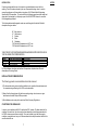
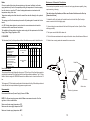
Dimensions:
Installation
SF1053CP
Installation must be carried out in accordance with the instructions supplied and be
installed by a qualified and competent person
57
115
45
130
Installations must comply with all Local and National Water Authority Regulations, and
Building/Plumbing Regulations.
- Care must be taken during installation to prevent any risk of injury or damage.
- The hole in the basin must consist of a diameter of 30mm to 36mm.
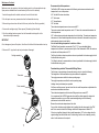
- The tap needs to be positioned to allow access to the grub screw on the back of the tap.
- To eliminate pipe debris entering the valve it is essential that supply pipes are flushed
thoroughly before connecting to the inlet tails.
FINAL INSTALLATION
1. Ensure the inlets tails are fully tightened into the base unit.
60
155
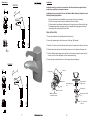
2. Secure the clamping studs into the base unit of the tap. (M6 threads).
3. Place the ‘O’ seal over the inlet tails and into the groove located onto the bottom of the tap.
4. Place the base unit seal over the inlet tails and secure on to the bottom of the base unit.
15
5. Place the flexible hoses/copper pipes through the sink hole and clamp the tap to the sink,
connect up to the 15mm inlet pipes. (15mm compression fixing).
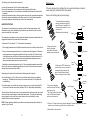
6. Secure the tap in place with the rest of the clamping kit as per diagram.
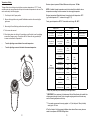
SF1054CP
57
115
Tap body
O’ring groove
45
130
Base unit
O’ring
M6 Clamping stud
2 off
Flexible Hoses or
Copper Tubes
Clamping ring
Base unit seal
Clamping stud nut M6
2 off
NOTE: This seal sits
on underside of basin.
155
7/16” across flats
hexagon
15
7
8